CTEP125S-4R0M中文资料
- 格式:pdf
- 大小:205.00 KB
- 文档页数:1
Broadband TelCom Power, Inc. BTCPower TM Redefining “Current” Limits In Power Conversion BTCPower4EE Series 25-30W DC-DC Converters Features• 25W Isolation output• 4:1 Input Range• Six-sided Shield• Remote On/Off Control• Efficiency To 82%• 200KHz switching frequencyModel Input Output Output Input Current % Efficiency Case Number Voltage Voltage Current No Load Full Load4EE-01 5 VDC 3000 mA15 mA 810 mA 774EE-02 12 VDC 1250 mA15 mA 780 mA 804EE-03 15 VDC 1000 mA15 mA 780 mA 804EE-04 9-36 VDC ±12 VDC±625mA20 mA 780 mA 80 E 4EE-05 ±15 VDC±500mA20 mA 780 mA 804EE-06 5/±12 VDC 1500/±310 mA20 mA 780 mA804EE-07 5/±15 VDC 1500/±250 mA20 mA 780 mA804EE-08 +5/+12/-5 VDC 1500/310/500 mA20 mA 715 mA804EE-11 5 VDC 3000 mA10 mA 410 mA774EE-12 12 VDC 1250 mA10 mA 390 mA804EE-13 15 VDC 1000 mA10 mA 390 mA804EE-14 18-72 VDC ±12 VDC±625mA15 mA 380 mA82 E 4EE-15 ±15 VDC±500mA15 mA 380 mA824EE-16 5/±12 VDC 1500/±310 mA15 mA 380 mA824EE-17 5/±15 VDC 1500/±250 mA15 mA 380 mA824EE-18 +5/+12/-5 VDC 1500/310/500 mA15 mA 350 mA82Note: Nominal Input Voltage 12, 24, 28 or 48VDCBroadband TelCom Power, Inc. –1719 S. Grand Avenue, Santa Ana, CA 92705 U.S.A. Tel.: 714-259-4888 • Fax: 714-259-0840• • Email: sales@ DS LP 4EE Rev2 16-1-044EE Series 25-30W DC-DC ConvertersBTCPower BTCPowerT MBroadband TelCom Power, Inc. – 1719 S. Grand Avenue, Santa Ana, CA 92705 U.S.A.Tel.: 714-259-4888 • Fax: 714-259-0840• • Email: sales@ DS LP 4EE Rev2 16-1-04SpecificationsInput Specifications:Input Voltage Range…………….……24V……...………………..9-36V 48V……………………..18-72V Input Filter…………………………………………………..……..Pi Type Output Specifications: Voltage AccuracySingle output………………………..…………………….+/- 1.0 % max. Daul output………………………………………………..+/- 3.0 % max. Triple, 5V………………………………………………….+/- 2.0 % max. 12V/15V…………………………………………..………+/- 3.0 % max. Voltage Balance ( Dual )………………………………...+/- 1.0 % max. External trim Adj. Range……………………………..…………+/- 10% Ripple & Noise, 20 MHz BW……………………….… 75 mV p-p max. Temperature Coeffcient………………………… +/- 0.02 % / ºC max. Short Circuit Protection………………………………..……Continuous Line Regulation ¹ Single / Dual Output………….……..+/- 0.2 % max. Triple………………………….………..+/- 1.0% max. Load Regulation ² Single / Dual Output…………….….+/- 1.0 % max. Triple………………………..…………+/- 5.0 % max. General Specifications :Efficiency………………………………………………..……..see table Isolation Resistance…………………………………………..100Mohm Switching Frequency……………………………………..200 KHz, min. Operating Temperature Range…………………………-25ºC ~ +71ºCCase Temperature………………………………………….100 ºC max. Cooling……………………………………………….Free air convection Storage Temperature Range……………………..…..-55 ºC ~ +105ºC Isolation Voltage………………………….………………..500VDC min. EMI/RFI…………………………………….....Six-sided continus shield Dimensions…………………2.65” x3” x 0.83 “(65 x 76.2 x 21.1 mm) Case Material……..Black Coated Copper with Non-conducted baseTriple output loading tableOuput Voltage Amperes (pin no.)(V) Min. (2) Nom. 6 +5 0.25 1.5 3 & 5 +12 or -12 0.1 0.31 3 & 5 +15 or -15 0.1 0.25 3 & 5+12 or -50.1/0.1 0.31/0.5Note: 1. measured from high lin to low line2. measured from full load to ¼ load3. maximum total power from all outputs is limited to 25/30W but no output should be allowed to exceed its maximum current4. minmum current on each output is required to maintain specified regulationOutline Information and Pin-outPin ConnectionPin Single Dual Triple 1 +Input +Input +Input 2 -Input -Input -Input 3 No pin +Output+Output 4 Trim Common Common 5 No pin -Output -Output 6 +Output No pin +5V output 7 -OutputNo pin No pin 8 Remote On/Off ControlRemote On/Off ControlLogic compatibility CMOS or Open collector TTL E c-0n >5.5 Vdc or open circuit E c-Off <1.8 Vdc Shutdown Idle current 10mA Input resistance 100K ohms (Ein 0Vdc to 9Vdc) Control common referenced to Input minus External Output TrimmingOutput may optionally be externally trimmed (+/-10%) with a fixed resistor or an external trimpot as shown.。
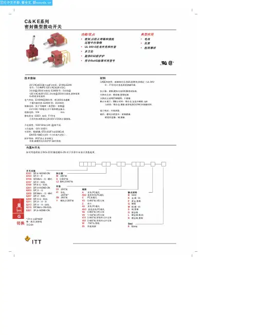

KUTAI ELECTRONICS INDUSTRY CO., LTD.TCS4P125Automatic Transfer SwitchControl Unit for 3 Phase 4 Wire SystemOperation ManualThree Phase Four Wire 4P 125 Amp Rated Voltage 250 VacPatent Number : U.S. Pat. No. 7,557,683TABLE OF CONTENTSSection PageSECTION 1 : INTRODUCTION1.1 Safety Precautions (3)1.2 Products Overview (3)SECTION 2 : HARDWARE DESCRIPTION2.1 Front Panel (4)2.2 TCS4P125 Dimensions (5)2.3 Panel Cut-Out For The TC-V2 (5)SECTION 3 : FUNCTION DESCRIPTION3.1 General (6)3.2 TDNE Setting (6)3.3 TDEN Setting (6)3.4 TDEC Setting (6)3.5 TDES Setting (6)3.6 TD-OFF Setting (6)3.7 Plant Exerciser (6)3.8 Over / Under Voltage Sensing (6)3.9 Transfer Failure (6)SECTION 4 : OPERATION4.1 General (7)4.2 AUTO Mode (7)4.3 TEST Mode (7)4.4 Programming Mode (7)4.5 AC Voltage Display Adjustment (7)4.6 Specification Summary (7)4.7 System Setting Reference Table (8)SECTION 5 : INSTALLATION INSTRUCTIONS5.1 General (9)5.2 Installation On The Plate (9)5.3 TC-V2 Installation On The Door Panel (10)SECTION 6 : TYPICAL WIRING6.1 TCS4P125 Standard Wiring Diagram (11)SECTION 1 : INTRODUCTION1.1 Safety Precautions (WARNINGS)This manual covers the installation, operation and maintenance of the TCS4P125 Automatic Transfer Switch. It is intended for qualified personal only.1.2 Products OverviewThe TCS4P125 automatic transfer switch consist of two parts the TS4P125 switch and the TC-V2 electronic control unit :1.2.1 TS125 FeaturesThe contacts on the Kutai TS4P125 transfer switch are class PC, this means that it is capable of making and withstanding short circuits but is not intended for breaking short circuit current.●Rated operating Voltage:250 Vac●Rated operating Current:125 Amps●Number of poles:4P●Coil operating voltage:110 / 220 Vac +/- 20%●Compact size, light weight and low powerconsumption.●Electrically operated and mechanically held.●Manufactured using UL 94V-0 plastics.●Adjustable time delay in OFF position whentransferring.●Designed for cell-phone repeaters, and manyindustrial and home ATS applications.1.2.2 TC-V2 Digital ControllerThe TC-V2 digital control unit offers programming flexibility to customize the ATS to different customer requirements.The Controller:●Monitor normal source for full phase over and undervoltages.●Monitor emergency source for single phase overand under voltages.●Normal & emergency source voltage and frequencyparameter display.●TDEN, TDNE, TDEC and TD-OFF real timecountdown display.●Permit testing the transfer switch from the controlpanel.●Permit system testing the transfer switch with orwithout load from the front panel.●Built-in 1 to 4 weeks exerciser timer.●Permit customer plant exerciser test with / withoutload on a preset period.●Safely store customer / factory settings inpermanent memory.●Shows status and failure alarm LED’s on the frontpanel.●No need for PC connection and programmingsoftware. All settings can be made on site.●Controller can be installed next to switch orseparately on an enclosure panel.SECTION 2 : HARDWARE DESCRIPTION 2.1 Front Panel2.2 TCS4P125 Dimensions (Unit : mm)2.3 Panel Cut-Out for the TC-V2 (Unit : mm)SECTION 3 : FUNCTION DESCRIPTION3.1 GeneralOperation of the TCS4P125 electronic control.3.2 TDNE SettingsTDNE provides a time delay when transferring from N ormal to E mergency. Timing begins when the Emergency Source (generator) becomes available. TDNE:Adjustable from 0 to 99 seconds.3.3 TDEN SettingsTDEN provides a time delay when transferring from Emergency to Normal. This permits stabilization of the Normal Power before transferring back to normal. Timing begins when the Normal Power returns and becomes available and steady.TDEN:Adjustable from 0 to 99 seconds.3.4 TDEC SettingsTDEC timer keeps the generator running without load (E ngine C ool-down) after the ATS transfer back to Normal Power. Timing begins when the transfer back to normal is completed.TDEC:Engine Cool-down - from 0 to 99 sec.3.5 TDES SettingTDES is the time delay for Engine Start when the Normal Source voltage is in over or under-voltage (OV or UV). If power return to normal while timing, the TDES timer resets and starts again.TDES:Adjustable from 0 to 30 seconds.3.6 TD-OFF SettingTime Delay on OFF this timer keeps the switch in the center neutral OFF position (completely disengaged) before transferring to the other side. You can preset the switch in Neutral or OFF from 0 to 18 seconds (Normally 2 to 3 sec).TD-OFF:Adjustable from 1 to 20 seconds.3.7 Plant ExerciserThis feature provides for automatic test operation of the generator. The interval is fixed at once per 1 to 4 weeks with a specific test day and time. The exerciser can be set for either testing with load or without load. When the exerciser is activated the exerciser LED (EX) on the right side of display flashes and turns on during the exercise period.3.8 Over / Under Voltage SensingThe TC-V2 constantly monitors normal & emergency power. When power falls outside the programmed voltages this LED turns RED from GREEN and flashing to show OV / UV problems.Adjustable over voltage range:110 - 280 VacOver voltage reset:When voltage falls below 10 Vac of the OV setting.Adjustable under voltage range:80 - 230 VacUnder voltage reset:When voltage exceeds 10 Vac of the UV setting.3.9 Transfer FailureWhen a transfer is made the TS125 communicates it’s position to the TC-V2 controller by using two small internal micro-switches, if this signal is not received, it will try switching 3 more times every 2 seconds or until the connection is made. A flashing light indicator and a “FAIL” signa l displayed an incomplete transfer and that the ATS mechanism or wiring is defective.If the ATS fails, the TC-V2 controller stops all ATS functions and starts’ flashing until the failure is corrected and the control is reset.To reset the transfer fail alarm:1. Manually move the ATS to the correct position.2. Press any button (Auto, Program or Test) on thefront panel to reset the alarm.SECTION 4 : OPERATION4.1 GeneralThis section specifically describes the operation and functional use of the TC-V2 controller.4.2 AUTO ModeIn AUTO the TC-V2 controller automatically transfer and retransfers from source to source as directed by the pre-programmed instructions.In AUTO the controller monitors the condition of both normal and standby power sources providing the logic for the transfer operation.4.3 TEST ModeThe TC-V2 is equipped with a test pushbutton that simulates the loss of normal source. Pushing the Test key the TC-V2 will execute a test on the ATS. The TDES and TDNE programmed time delays will be performed as part of the test. There are two test modes:●Testing with load .●Testing without load4.4 Programming ModeThe TC-V2 controller is fully programmable from the front panel when in the Program Mode. The build-in program buttons have multiple functions:●Real time clock displaying●Programming mode operatingTo enter programming mode, push and hold Program button for 10 seconds. In the first 10 seconds the screen showing internal real time clock and then the word “ Vr 1.0” will appears on the front display window for 2 seconds indicating the version of the software.At this time start a line by line programming sequence. To advance to the next line, push the Program button on the front panel. To change each line’s programming parameters, press the increase (∧) and decrease (∨) buttons. When pressing and releasing the (∧) or (∨) key the displayed parameter can be increased or decreased by one. The parameter will continue to scroll if the (∧) or (∨) button is pressed and not released. Always push the “ Program” button to advance to the next line or until the word “ End” appears on the screen. To immediately end the programming mode, you simply push the “ Program” button for 4 seconds. Then the word “ End” shows on the screen indicating the end of the programming mode.If you like to return to factory settings, stay in programming mode and simultaneously press all 3 buttons (∧), (∨) and Program buttons for 4 seconds. The TC-V2 will now automatically program itself to factory settings and the word “ Au.Po” will appear on the display window.4.5 AC Voltage Display AdjustmentThe TC-V2 controller continually monitors normal & emergency power displaying volts and frequency on the front panel. (The voltage value is calibrated and adjusted at the factory). But when the ATS works on high capacitive or inductive loads the waveform distortion may cause the displayed to have slight differences from the users measuring instrument.You can adjust the display value to equal to the users own instruments, by entering the setting mode to perform adjustment the parameter. Once the adjustment is completed, the voltage sensing value will increase or decrease according to the adjusted value and display it on the screen. The TC-V2 over and under voltage protection follow the adjusted value as the actual system voltage and perform the monitoring according to the new parameter.See Table lines 2, 3, 4, 5 for voltage display setting. 4.6 Specification Summary4.7 System Setting Reference TableSECTION 5 : INSTALLATION INSTRUCTIONS5.1 GeneralThe TC-V2 controller is modular and is designed for installation next to switch or on the front door panel. A longer harness is required for door installation.5.2 Installation On The Plate5.3 Installation On The Door PanelSECTION 6 : TYPICAL WIRING6.1 TCS4P125 Standard Wiring Diagram (110 or 220V)___________________________________________________________________________________________ TCS4P125(TC-V2)11。