
Ch8 Switch-mode dc-ac inverters
- 格式:ppt
- 大小:629.50 KB
- 文档页数:58


Review (23-jun-09 by li zhen zhen)CH 00 & CH 241.CFRP is mainly used for primary structures, whilst AFRP and GFRP are only used forsecondary structures.2.In normal operation, only green lights and sometimes blue lights are illuminated.3.The annunciator light test unit is located at the right side of electronic avionics compartment.4.The engine sectionbase number is 40.The landing gear section base number is 50.The general belly fairing section base number is 60.5.The C/Bs with a yellow cap must be tripped when flying on batteries only.6.IDG FAULT light come on in case of overheat or low pressure dectection.The low pressure warning is inhibited, for IDG input speed below 2000 RPM(Normal input speed range: between 4500 and 9120 RPM).7.To disconnect the IDG from the accessory gearbox, the IDG pushbutton must be pressed.8.When the filter is clogged, the relief valve opens.9.In cold conditions, the cooler bypass valve opens;As the oil warms up, the cooler bypasscloses.10.The priorities of AC distribution are:1 - GEN 1 (2) on AC BUS 1 (2)2 - EXT PWR even with one engine generator still running.3 - APU generator4 - The remaining engine generator.11.Generators are never connected in parallel on the same bus.12.The AC ESS BUS is normally supplied by AC BUS 1, or by AC BUS 2 if AC BUS 1 fails.13.If AC BUS 1 and 2 are lost above a given airspeed (100Kts), the Ram Air Turbine will extendautomatically.14.When blue hydraulic system is pressurized, a loss of AC BUS 1 and AC BUS 2 and a speedhigher than 100 knots, the EMER GEN TEST pushbutton is pressed in, RAT extension is inhibited.15.A Static Inverter transforms the DC from battery 1 into 115V, 400Hz, single phase AC.16.(V between 50 and 100 Kts) The AC ESSential Bus is supplied by the Static Inverter and theAC STATIC Inverter Bus is also supplied by the Static Inverter. This bus is used for the APU fuel pump supply.17.Overheat of Static Inveter will be monitored by The Battery Charge Limiter (BCL).18.Each Transformer Rectifier control logic consists of an overheat protection and a minimumcurrent flow detection to isolate the distribution circuit from the Transformer Rectifier.19.The Transformer Rectifier protection reset is possible either from the Centralized Fault DisplaySystem via MCDU or from the pusbutton located in the avionics bay.20.The voltmeters, located on the main control panel, give battery voltage indication even in a coldaircraft configuration.21.The DC battery BUS supply from DC BUS1, DC BUS2 and BATTERY.22.The DC ESS BUS is supplied by the DC BAT BUS. In an emergency, it is supplied either byBAT 2 or by the ESS Transformer Rectifier.23.When the EMER GEN is available, it supplies the AC ESS BUS and via ESS TR, the DC ESSBUS.24.If the External Power parameters are correct, the indicator lights on the external powerreceptacle and the EXTERNAL POWER AVAILABLE light on the cockpit overhead panel come on.25.External power is available but not in use and while MAINT BUS SWITCH is on, Only the ACand DC GRND Buses are supplied.26.The MAINT BUS switch is located in the forward galley area (ceiling panel).27.The Ground Power Control Unit (GPCU) is supplied by the Ground Cart through the ExternalPower receptacle and receives a back-up supply from the DC BAT BUS28.29.If the Generator Control Unit detects a generator overload, the GALLEY FAULT light comes on.In this case the galleys have to be manually cut off.30.As soon as r efuel door is opened, Refueling busbars are then supplied by service bus. Whensupplied by HOT BUS, it will be closes after 10mn, refueling power is automatically cut off even if refuel door is still open.31.The GPCU is the interface between the GCUs and the CFDIU.24-JUN-09CH 311.The EIS (Electronic Instrument Systems) presents data for:- Electronic Flight Instrument System (EFIS).- Electronic Centralized Aircraft Monitoring (ECAM).The 6 Display Units (DUs) are identical and interchangeable2.ATTENTION GETTERS-- The warning messages are accompanied by either a MASTER WARNING, or a MASTER CAUTION and an aural warning.3.MASTER WARNING LIGHT is flashes red for any red warningMASTER CAUTION LIGHT comes on amber for level 2 amber warning.4.The displays can be transferred automatically if a system failure is detected. It is also possible to transfer them manually. See attached5.Each FWC generates all warning messages to be displayed and supplies the attention getters.It also computes the flight phases and provides aural warnings6.The SDACs acquire most of the signals used to display system pages and used by the FWCs to generate amber warnings7.System Display: The upper area displays system or status pages, the lower area permanent data.8.The Gross Weight (GW) is shown in green. It is inhibited before flight phase 2 and after flight phase 9.9.The cruise page is only automatically called in flight.10.At the bottom of the System Display, permanent data is always displayed whatever the page presented. TAT, SAT, G LOAD, TIME & GW.11.The flight phases are computed by the FWCs.12.The ENG page appears during the Engine start sequence and it will be replaced by the WHEEL page after the Engine start sequence.13.FLIGHT PHASE 1: DOOR/OXY PAGEFLIGHT PHASE 2: WHEEL PAGE -- The FLT/CTL page replaces WHEEL page for 20 seconds when either sidestick is moved or when rudder deflection is above 22 degreesFLIGHT PHASE 3,4,5: ENGINE PAGE-- T.O INHIBIT is displayed on the E/W display.FLIGHT PHASE 6: CRUISE PAGE -- T he CRUISE page appears as soon as SLATS are in and the engines are no longer at take-off power. It disappears when the L/G is selected down(WHEEL page back). The T.O inhibit message disappears. The CRUISE page is alsodisplayed on ground when an ANN LT TEST is performed.FLIGHT PHASE 7: WHEEL PAGE -- LDG INHIBIT is displayed on the E/W displayFLIGHT PHASE 8: WHEEL PAGE -- LDG INHIBIT is displayed on the E/W displayFLIGHT PHASE 9: WHEEL PAGE -- The LDG INHIBIT message disappears14.FLIGHT PHASE 10: DOOR PAGE -- 5 minutes after 2nd engine shutdown, the FWC starts a new flight leg in phase 115.EMER CANCWhen pressed :1 - Any present aural warning is cancelled.2 - In case of a red WARNING, the MASTER WARNING and ECAM message remain displayed.3 - In case of an amber CAUTION, the MASTER CAUTION and ECAM messages arecancelled for the rest of the flight.The STATUS page is automatically called with the white "CANCELLED CAUTION" message and the failure title16.The EMER CANC inhibition can be manually restored by pressing RCL for more than 3 sec.17.CLR button of ECAM control panel comes on as long as a WARNING/CAUTION message or a STATUS message is present on the ECAM DU18.The RCL pushbutton allows the crew to recall warnings, When pressed, the WARNING/CAUTION messages which have been cancelled are recalled19.T he alerts are classified in three levels. They depend on the importance and urgency of the corrective actions required.- Level 3: warnings (highest priority)- Level 2: cautions- Level 1: cautions- Status messages20.The failures may be of three different types, independently of their classification. There are 3 separate types of warnings or cautions:- those associated with an independent failure,- those associated with a primary failure,- those associated with a secondary failure21.The titles of the system pages corresponding to the secondary failures are indicated on the lower right part of the E/WD by an asterisk.22.The flight mode Annunciator (FMA) provides basic information concerning flight management and guidance system operation23.ROSE/NAV -- The ROSE/NAV mode displays a 360 degree dynamic pattern which provides the aircraft position with respect to the flight plan.ARC MODE -- The ARC mode displays a forward 90 degree dynamic pattern which provides the aircraft position with respect to the flight plan.The PLAN mode displays a true North up oriented static map24.DU receives digital signals from its related DMC through a Master DSDL, and through four digital buses for the weather radar link.25.The three DMCs receive aircraft system data on ARINC 429 buses, and weather radar information on ARINC 453 high speed bus.26.The ECAM Control Panel outputs discretes for the Clear (CLR), Recall (RCL), Status (STS) and EMERgency CANCEL keys wired to the FWCs, and for the ALL key wired to the DMCs27.FAILURE OF ONE FWC -- There is no operational consequence due to the redundancy of the EIS system.28.The Electrical Clock is located on the right center instrument panel and provides Universal Time Coordinated (UTC), Elapsed Time (ET), Chronometer and Date25-JUN-09CH 311.Centralized Fault Display System (CFDS) which monitors the BITE data in order to record thesystem failures through the CFDIU.2.All the information necessary for maintenance and troubleshooting is memorized in a NonVolatile Memory (NVM).3.The Centralized Fault Display Interface Unit (CFDIU) consists of two distinct channels:- A NORMAL CHANNEL which ensures all the functions.- A STANDBY CHANNEL which permits restricted operation when the normal channel is faulty.4.the CFDIU dialogues with one Multipurpose Control and Display Units (MCDUs) at a time5.Two CFDS modes are available. The NORMAL MODE is always active except on ground whenthe MENU MODE is selected.6.In flight the CFDS always operates in the normal mode.7.MENU MODE can only be selected on ground and interrupts the normal mode of operation.8.The POST FLIGHT REPORT (PFR) is the sum of the LAST LEG REPORT and of the LASTLEG ECAM REPORT.9.The POST FLIGHT REPORT(PFR)can only be printed on ground.10.11.The failures are classified according to their importance:- Class 1 failures are the most serious ones and require an immediate maintenance action subject to the Minimum Equipment List (MEL).- Class 2 failures may have consequences if a second failure occurs. A maintenance action is necessary at the next adequate opportunity.- Class 3 failures can be left uncorrected until the next scheduled maintenance check.12.Type 1 System -- Most systems are type 1 systems. These systems can memorize failuresoccured in the last 64 flight legs. Type 1 systems are connected to the Centralized FaultDisplay Interface Unit (CFDIU) via an ARINC 429 input bus and an ARINC 429 output bus.Type 2 System -- Type 2 systems memorize only failures from the last flight leg. The discrete signal is provided to initiate the test of the systemType 3 System -- TYPE 3 systems are simple systems linked to the CFDS by only two discrete signals. Type 3 systems cannot memorize failure messages.13.You can display the class 1 failures on the Multipurpose Control and Display Unit (MCDU):- in the LAST (or CURRENT) LEG REPORT.- in the LAST (or CURRENT) LEG ECAM REPORT.Refer to the Minimum Equipment List (MEL): "GO", "GO IF" or "NO GO".14.Class 1, Class 2 & Class 3 failures can be display on the AVONICS STATUS page of MCDU15.Class 2 failures have no immediate operational consequence and can be displayed on requeston the ECAM STATUS page, under the MAINTENANCE title. You can display the class 2 failures on the MCDU:- in the LAST (or CURRENT) LEG REPORT.- in the LAST (or CURRENT) LEG ECAM REPORT.A class 2 failure has to be repaired within 10 days. Refer to the MEL: "GO" without condition.16.Class 3 failures have no operational consequence. All aircraft systems remain available. Youcan display the name of the systems affected by at least a class 3 failure in the AVIONICS STATUS. Do not refer to the MEL17.On ground, all the functions are available.In flight, only CURRENT LEG REPORT and CURRENT LEG ECAM REPORT are available.Note that the CFDS menu comprises two pages.18.Note that red stripes on the paper indicate end of roll.19.The SSFDR is automatically supplied from the first engine start up to five minutes after the lastengine shutdown. The GrouND ConTroL (GND CTL) pushbutton enables the SSFDR to be supplied, via the power interlock circuit, when the aircraft is on the ground for preflight check before engine start or for test and maintenance purposes.20.Maintenance has to be performed at determined time intervals to replace the battery of theULB.21.FLIGHT PHASE 6: CRUISE PAGE disappears when the L/G is selected down (WHEEL pageback).22.To test the clock, the annunciator light switch must be set to TEST...。

For more instructions about the use of this product (including the Headset Companion app), visit /helpme.ENPrecautionsBefore using this product, carefully read this manual and any manuals for compatible hardware. Retain instructions for future reference.SafetyˎObserve all warnings, precautions, and instructions.ˎCHOKING HAZARD - Small parts. Keep out of the reach of small children.Use and handlingˎStop using the wireless headset immediately if you begin to feel tired or if you experiencediscomfort or pain in your head while operating the wireless headset. If the condition persists, consult a doctor.ˎAvoid prolonged use of the wireless headset. Take a break at about 30-minute intervals. ˎPermanent hearing loss may occur if the headset is used at high volume. Set the volume to asafe level. Over time, increasingly loud audio may start to sound normal but can actually be damaging your hearing. If you experience ringing in your ears or muffled speech, stop listening and have your hearing checked. The louder the volume, the sooner your hearing could be affected. To protect your hearing:ˋLimit the amount of time you use the headset at high volume. ˋAvoid raising the volume to block out noisy surroundings.ˋLower the volume if you can’t hear people speaking near you.ˎIf you feel that the headset is irritating your skin, stop using it immediately. ˎDo not expose the headset to high temperatures, high humidity or direct sunlight. ˎDo not put heavy objects on the headset.ˎDo not allow liquid or small particles to get into the headset.ˎDo not throw or drop the headset, or subject it to strong physical shock.ˎDo not place any rubber or vinyl materials on the headset exterior for an extended period oftime.ˎUse a soft, dry cloth to clean the headset. Do not use solvents or other chemicals. Do not wipewith a chemically treated cleaning cloth.ˎDo not disassemble or insert anything into the headset because this may cause damage to theinternal components or cause injury to you.ˎObserve all signs and instructions that require an electrical device or radio product to beswitched off in designated areas, such as gas/refueling stations, hospitals, blasting areas, potentially explosive atmospheres or aircraft.ˎThe battery used in this device may present a risk of fire or chemical burn if mistreated. Do notdisassemble, heat above 60 °C / 140 °F, or incinerate.Wireless headsetHeadset: CUHYA-0080Wireless Adaptor: CUHYA-0081Instruction Manual Part names and functionsPower/audio mode switchSets the audio mode or turns off headset.Positions:OFF - turns off the headset 1 - Standard Mode2 - Bass Boost Mode (default)This mode can be replaced with audio modes from the Headset Companion app.Adjusts the volume of the headset.MUTE buttonˎPress to switch microphone MUTE on and off. ˎTo engage the sidetone feature, hold down the MUTE button until a beep is heard. Then cycle through the sidetone volume settings (high, medium, off) by holding the MUTE button.Sidetone is a feature that allows you to hear your own voice from the headset. The sidetone volume is adjusted here, and not on the PS4™ system or other devices. When MUTE is on, the sidetone feature is turned off.L markingWhen the included audio cable is connected to the headset for use with mobile devices, the wireless function is turned off.Wireless adaptorReset button Status indicatorˎOn PlayStation®Vita systems, you can listen to audio in standard stereo formatand use the voice chat feature.ˎOn other mobile devices, you can listen to audio in standard stereo format only.HintsˎWhen the included audio cable is connected to the headset, the VSS (Virtual Surround Sound) button and the SOUND/CHAT buttons cannot be used. ˎOutput volume varies depending on the portable device that is connected. Adjust volume accordingly.ˎYou can use the supplied audio cable to connect the headset to your mobile device to listen to audio content and talk on the phone. ˋ I f you are unable to hear audio content using the cable with your mobile device, turn off headset power. ˋ Y our device may only support use of a standard audio cable (not included) to listen to audio content using the headset. Note that standard audio cables do not support voice communication. ˋ T his product is not compatible with all mobile devices. Some features may not work on all mobile devices.Charging the headsetWhen remaining battery level is low, the status indicator flashes red and a beep is heard. Charge the battery by connecting the headset to a supported USB device such as a PC. While the battery is charging, the status indicator lights up red. The status indicator light turns off when the battery is fully charged.HintsˎYou can view the remaining battery charge on a PS4™ system. It is shown on the status display that appears when you change the headset settings.ˎYou might not be able to charge the battery if the USB device or the USB hub does not provide enough power for charging. Try connecting the headset to a different USB device or a different USB connector on the device.ˎCharging takes approximately 3.5 hours when starting with no battery charge left. ˎWhen the remaining battery charge is low, the headset beeps while it is connected and receiving an audio signal.ˎIt is recommended that you charge the battery in an environment with atemperature of 5 °C - 35 °C / 41 °F - 95 °F. Charging in other environments might not be as effective.ˎIf you do not plan to use the wireless headset for an extended period of time, it is recommended that you fully charge it at least once a year to help maintain battery functionality.Status indicator displayHeadset1 F or repair options, visit /helpme.2 I f you see the flashing error light, retry the steps to Restore Headset again. If you continue to see the error after the Restore attempt, then visit /support/wirelessstereoheadset.Wireless adaptorInitial setup1 Charge the headset by connecting it to a USB port with a USB cable.The headset may need up to 3.5 hours to charge fully.2 Insert the wireless adaptor into the USB port.3 Slide the power switch on the headset to position “1” or “2”.Using the headset with PlayStation ®4 systemsThis headset is compatible with PS4™ system software version 5.00 or later. More than one headset can be used with a PS4™ system.Always update your system software to the latest version.Status displayWhen first connecting to a PS4™ system or when changing the settings, thefollowing status information is displayed in the upper left corner of the screen:Stereo Headset Audio Extension is a system setting that controls the type of audio output to the wireless headset. It is available only when the wireless adaptor is inserted.Audio output selectionWith the wireless headset you can listen to audio from the PS4™ system—including music, videos, and games—in Virtual Surround Sound.ˋYou can listen to both game audio and chat audio simultaneously.Use the SOUND/CHAT buttons to adjust the relative volume of game audio versus chat audio.ˋYou can change the audio output to the headset so that you can hear only chat audio.To change the audio output select (Settings)(Devices)[AudioDevices] [Output to Headphones]. NOTE:O n a PS4™ system, the wireless headset defaults to “ON” [All Audio].Using the headset with a computerYou can use the headset with a PC (with Windows® or macOS) that has a USB port. Insert the wireless adaptor into a USB port on the computer you want to use and then turn on the headset.HintsˎThe headset might not work with some computers.ˎThe VSS (Virtual Surround Sound) button and SOUND/CHAT buttons can be used only when the headset is connected to a PS4™ system .Using your headset with PlayStation ®VRYou can use an audio cable to connect your headset to the stereo headphone jack of PlayStation ®VR. This will output all game audio processed by the PlayStation ®VR,including 3D audio if supported by the game title.NoteThis headset only supports stereo or 7.1 virtual surround sound. 3D audio is supported on this headset only when plugged into the PS VR, while playing a PS VR game that supports 3D audio.Using the headset with a portable deviceYou can use an audio cable to connect your headset to the headphone jack of compatible devices.Headset Companion appWith the Headset Companion app, you can select an additional audio mode for your headset. There are several modes to choose from, each optimized to enhance different audio characteristics. These modes are developed exclusively for use with PS4™ systems.To get one of these audio modes, download the Headset Companion app from PlayStation™Store and follow the on-screen instructions.Once this process is complete, you can experience your selected mode on your headset by sliding the power/audio mode switch to position “2”.Resetting the headsetIf the headset does not respond when you try to operate it, reset it by doing the following:1Connect the wireless adaptor to a PS4™ system or other powered USB port.2 Insert a small pin or similar object (not included) into the hole surrounding the reset button in the wireless adaptor, and push in for at least one second.3 On the headset, hold down the MUTE button and the VSS button.4 While still holding down the MUTE button and the VSS button, slide thepower/audio mode switch to position “1” or “2”.Rating labelThe rating label contains specific model, manufacture and compliance information. It is located under the right earpad.To remove the earpad and access the rating label:1 Use one hand to hold the headset in place.2 With your other hand, grip the earpad frame.3 P ull the earpad out.To replace the earpad, align the earpad with the inner frame. Push it back onto the frame until it clicks.End of life product recyclingThe wireless headset is made of plastics, metals, and a lithium-ion battery. Follow localregulations when disposing of the wireless headset. Sony products can be recycled for free in the United States and Canada by dropping the product off at a number of nationwide locations. For details, visit /SonyInfo/csr/SonyEnvironment/spotlight/.VSS (Virtual Surround Sound) buttonThe Virtual Surround Sound effect is on by default. Press and hold for more than one second to turn the VSS on or off.繁體中文使用前須知事項使用本產品前,請先詳細閱讀本說明書及對應裝置的說明書,並妥善保存,以備將來參考之用。

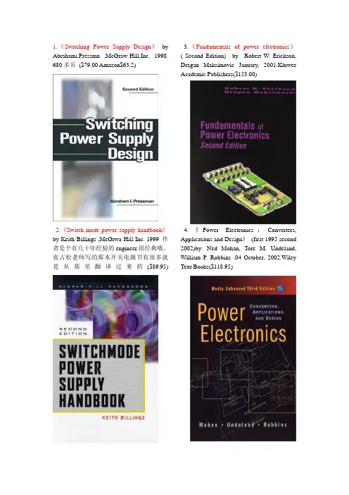
1.《Switching Power Supply Design 》 by Abrahami.Pressmn ,McGraw-Hill,Inc. 1998. 680多页($79.00 Amazon$63.2)2.《Switch-mode power supply handbook 》by Keith Billings ,McGrwa-Hill Inc. 1999 作者是个有几十年经验的engineer.很经典哦。
张占松老师写的那本开关电源书有很多就是从那里翻译过来的($89.95)3.《Fundamentals of power electronics 》( Second Edition) by Robert W. Erickson, Dragan Maksimovic January, 2001.KluwerAcademic Publishers($153.00)4.《Power Electronics :Converters, Applications and Design 》 (first 1995 second 2002)by: Ned Mohan, Tore M. Undeland, William P. Robbins .04 October, 2002.WileyText Books($118.95)5. 《Switch-Mode Power Supply SPICE Simulation Cookbook 》 by Christophe P. Basso, Daniel M. Mitchell, Christopher Basso ,McGrew-Hill,Inc.19 March, 2001.($65.00 Amazon $52.65)6.《SMPS Simulation With SPICE3 》by Steven M. Sandler 01 December, 1996,McGraw-Hill,Inc.($55.00Amazon$46.75)7.《Practical Design Power Supplies 》 by Ron Lenk, IEEE Power Electronics Society.31 July, 1998.McGraw-Hill.Inc.($69.95)8.《Practical Switching Power Supply Design 》by Martin Brown , 28 March, 1990.Academic Press.($74.95)9.《Simplified Design of Switching Power Supplies 》by John Lenk,27 March, 1996,Newnes ($31.95)10.《Power Supplies, Switching Regulators, Inverters, and Converters 》by Irving M. Gottlieb。