SR4-Plus_用户手册
- 格式:pdf
- 大小:3.32 MB
- 文档页数:18
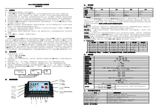
SR-LP 系列太阳能智能充电控制器使用说明书一、 主要特点1. 使用微处理器和专用控制算法,实现了智能控制。
2. 一路输出PWM 波形,配合恒流源可实现LED 数字调光,并且可以单独设置全功率和半功率工作时间,使用极其方便。
3. 五种负载工作模式:纯光控、光控+定时、手动、调试模式、自定义模式,其中自定义模式支持8时段任意调光控制。
4.科学的蓄电池管理方式,当出现过放时,对蓄电池进行提升电压充电,进行一次补偿维护,正常使用时,使用直充充电和浮充结合的充电方式,每7天进行一次提升充电,防止蓄电池硫化,大大延长了蓄电池的使用寿命;同时具有高精度温度补偿。
5. 参数设置具有掉电保存功能,即系统模式和控制参数等重要数据均保存在芯片内部,掉电后不丢失,使系统工作更可靠。
6. 充电回路采用双MOS 串联式控制回路,使回路电压损失较使用二极管的电路降低近一半,充电采用PWM 模糊控制,使充电效率大幅提高,用电时间大大增加。
7. LED 直观显示太阳能电池、蓄电池和负载的状态,数码管显示调节参数,让用户实时了解系统运行状况,并且具有丰富的参数设置,用户可以根据不同使用环境设置相应的工作模式。
8. 具有过充、过放、过载保护以及独特电子短路保护与防反接保护,所有保护均不损害任何部件,不烧保险;具有TVS 防雷保护,无跳线设计,可提高系统的可靠性、耐用性。
9. 所有控制全部采用工业级芯片和精密元器件,能在寒冷、高温、潮湿环境正常运行。
同时使用晶振定时控制,使定时控制更加精确。
10. 双位数字LED 显示,双按键操作,使用极其方便直观。
二、 系统说明本控制器专为太阳能直流LED 路灯系统、庭院灯等需要调光的场合设计,采用先进的PWM 数字调光技术,为客户提供高质量的调光方案,使LED 色温表现更加出众,同时有效控制系统功耗,使LED 亮灯时间更持久。
采用双按键,双位LED 显示,能分别控制全功率和半功率时间,使用更加灵活。

UMS4plus用户手册目录目录 (1)声明 (3)声明/担保与赔偿 (3)安全操作概要 (3)安装安全概要 (4)第1章产品简介 (5)1.1随附配件 (5)1.2产品概述 (5)1.2.1前面板图示 (7)1.2.2后面板图示 (8)1.2.4外形尺寸图 (9)第2章产品安装 (10)2.1连接信号源 (10)2.2插入电源 (10)2.3设备上电 (10)第3章产品使用 (11)3.1显卡拼接 (11)3.2软件安装 (13)3.3添加设备 (15)3.4添加媒体 (16)3.4.1添加媒体 (16)3.5图层设置 (18)3.5.1时间轴 (18)3.5.2控制命令 (19)3.5.3节目编排 (21)3.5.4特效编辑 (23)3.5.5输出设置 (25)3.6舞台预览 (26)3.6.1舞台窗体 (26)3.6.2节目预览 (27)3.7保存与导出 (28)3.7.1项目保存 (28)3.7.2项目导出 (28)3.8通用设置 (29)3.8.1通用 (29)3.8.2时间轴 (29)3.8.3保存 (30)3.8.4服务器 (30)3.8.5控制 (31)3.8.6快捷键 (31)第4章订购编码 (33)4.1产品编码 (34)4.2配件编码 (34)第5章技术支持 (34)5.1联系我们 (35)第6章附录 (36)6.1术语和定义 (36)6.2修订记录 (42)首先感谢您选购我们的产品!为了让您迅速掌握如何使用这款视频处理器,我们为您送上了详细的产品使用手册。
您可以在使用视频处理器之前阅读产品介绍以及使用方法,请仔细阅读我们所提供给您的所有信息,以便于您正确地使用我们的产品。
声明声明/担保与赔偿声明该设备经过严格测试,符合电子类数码设备的标准,根据FCC第15部分的规定,这些限制是为了合理地防止设备在商业环境中操作时的有害干扰。
如果没有安装和使用规定的指导手册,该设备的产生、使用和放射无线电频率,可能会对无线电通讯造成有害干扰。

Quick referenceSystem setupPrepping the catheter Step-by-step procedureTroubleshooting guidePioneer PlusIVUS-guided re-entry catheterE x t e n d e d n i t i n o l n e e d l eI V U S t r a n s d u c e rN e e d l e d e p t h m a r k e r s N e e d l e s t o p r i n g w i t h l o c kN e e d l e g u i d e w i r e l u m e nC o n n e c t o r f o r I V U S c o n s o l eH a n d l eN e e d l e d e p l o y m e n t w i t h a u t o l o c k r i n gSystem setup3 Prepping the Pioneer Plus catheter5 Step-by-step procedure11 Backloading12Introducing 12Use IVUS to precisely target13 re-entry into the true lumenExchanging Pioneer16 Plus catheterTroubleshooting guide:17 catheter tracking challengesInsertion into sheath18Tracking through the lesion19Troubleshooting guide:21 guidewire challengesLoading needle guidewire22Advancing wire out of needle22Exchange confusion due24 to multiple guidewires123System setupConfirm all necessary devices and equipment are in the lab before starting the procedure:1 Pioneer Plus catheter.2 Philips Volcano IVUS console andPatient Interface Module (PIM).3 Sterile cover/bag for IVUS PIM.4 10-cc syringe and RHV or Tuohy-Borst.5 0.014" nonhydrophilic guidewires withlong-coil transition (300 cm and 190 cmipsilateral/two 300 cm contralateral).Plug in and turn on Philips Volcano IVUS unit at start of procedure—system initialization takes ˜2 min.• IVUS settings:–Gain: 52–58–Diameter:–SFA: 10–12–ILIAC: 14–16–ChromaFlo: 3–5Confirm vascular sheath size is appropriatefor Pioneer Plus catheter use (6F or larger).456Prepping the Pioneer Plus catheter1 Remove the Pioneer Plus catheterfrom the box.2 Place plastic tray on sterile prep table.Carefully remove the Pioneer Plus catheter and all contents from the plastic tray.3 Inspect catheter for any manufacturingdefects or damage that may have resulted from shipping.4 Attach the white “winged” rapid exchangeflush adapter to a 10-cc syringe.5 Place the sterile plastic bagover the IVUS connector.6 Attach a Tuohy-Borst adapter orrotating hemostasis valve to the proximal luer on the handle.7 Set the needle stop to “7” and deploy theneedle to confirm needle movement.7a. Flushing rapid exchange lumenb. Flushing needle lumenVerify needle movement in and out of catheter shaft.8 Flush both lumens with heparinizedsaline as illustrated below:a. T he rapid exchange lumen requires the use of the white “winged” adapter. Gently insert tip of catheter into adapter until a snug fit is achieved and flush. Repeat before use, if necessary.b. N eedle lumen is flushed through theproximal handle luer with a 10-cc syringe. Use a stopcock or luer cap after flushing89 Insert PIM into the sterile bag. ConnectPioneer Plus catheter to the PIM andverify system recognizes catheter.The Pioneer Plus catheter works with the Philips Volcano s5 Series or CORE series ofPhilips Volcano systems. If an IVUS image is not obtained or is unsatisfactory, consult the Philips Volcano s5 Series or CORE Series of Systems Operator’s Manual supplied by Philips Volcano.10 Insert 300 cm guidewire* into needlelumen; place a 90º angle on wiretip. Retract needle first, then retractwire and reflush needle lumen.Carefully tighten the rotating hemostasis valve around the needle guidewire and close off the side port with a closed end cap of stopcock. Warning: ensure that the needle, Stop Ring and Deployment Ring are fully retracted prior to and during the introduction of the catheter into the peripheral vascular system.*Needle wire mustbe nonhydrophilicwith long-coiltransition.Step-by-step procedureIntroducing and advancing the Pioneer Plus catheter to the lesion1 Introduce the Pioneer Plus catheter into theperipheral vascular system using clinically accepted percutaneous techniques. Guide the catheter over the previously placedsupport 0.014” (0.36mm) tracking guidewire already in the vessel by “back-loading” the tracking guidewire into the guidewire lumen in the distal tip.2 Introduce Pioneer Plus catheter intovascular sheath and advance to the lesion. If tracking over the aortic bifurcation, make sure the curvature of the needle housing is in line with the curvature of the sheath.–Slight rotation of the Pioneer Plus catheter or balloon dilatation may be required toadvance the Pioneer Plus catheter.i.ii.iii.3 Use IVUS to precisely target re-entryinto the true lumena. O nce past the lesion, turn on the ChromaFlo feature and rotate thePioneer Plus catheter so the truelumen is at the 12 o’clock position.b. C onfirm catheterposition is correctusing fluoroscopy toidentify curvatureof needle housing.Tip: to ensure continuity of imaging, support the PIM connector extension with the hand that is rotating the Pioneer Plus catheter.4 After confirming catheter orientation, setthe needle stop (“3” for popliteal, “5” for SFA, “7” for iliac).5 Thumb-activated safety lock:Rotate needle deployment ringclockwise and deploy needle.6 Under fluoro, slowly advance needleguidewire out of needle—if you feelno resistance to wire movement,continue advancing wire into targetvessel lumen. However, if resistanceis felt, stop wire movement. Retractneedle slightly and advance wire.–If unsuccessful, retract the needle, then needle guidewire and repeat the stepsin this section. The catheter may requireslight advancement before additionalattempts to deploy needle.(Note: the needle must be retractedbefore retracting the needle guidewire.)Exchanging Pioneer Plus catheter7 Following successful true lumen access,retract the needle. Remove the subintimal tracking wire.8 Disconnect the Pioneer Plus catheterfrom the PIM.9 Back the Pioneer Plus catheter off ofneedle wire using short, smoothstrokes. This will leave the 0.014”needle guidewire in the true lumen.Catheter tracking challengesCatheter tracking challenges1 Shortly after introducing the PioneerPlus catheter into the femoral sheath,you feel significant resistance. Whatare the most likely causes?–The wrong sheath size may be in place—the system requires a 6F (2.2 mm) sheath.Although the catheter tip may passthrough a smaller sheath size, at the pointwhere the tracking wire exits the PioneerPlus catheter, the combined volume ofthe catheter shaft and guidewire willfit only through a 6F or larger sheath.–The catheter orientation may be such that resistance to tracking is maximized.The needle housing has a fixed curvature;significant resistance may occur if thecurvature of the needle housing isopposite that of the vascular sheath.–The tracking guidewire may needto be wiped clean or the trackinglumen may need to be flushed. Anybuildup of blood or other foreignmatter on the tracking guidewire caninduce resistance to movement.–The tracking guidewire or sheath may be kinked and should be replaced.2 After the Pioneer Plus catheter hasbeen advanced past the distal end ofthe sheath, significant resistance is feltwhile tracking through tissue, and thePioneer Plus catheter has reached a pointwhere further forward movement seemsimpossible. What are the possible causes?–The tracking wire may be kinked.–The Pioneer Plus catheter handle may be caught on a rigid section of the table.–The tissue morphology may be such that there is resistance to the catheter,inhibiting forward movement. Thisis especially true in highly calcifiedocclusions. If tissue resistance is believedto be the cause, a small-diameterballoon may be used to dilate the tissue.Remember, this is a technique commonlyutilized in subintimal angioplasty,and if the Pioneer Plus catheter isadvanced through significant resistancewithout adequate predilatation, theIVUS component may be terminallydamaged and/or the needle may kink.1920Guidewire challenges21Guidewire challenges1 While loading the needle guidewire into theneedle lumen, significant resistance is met.What are the most likely causes?–The needle guidewire tip may becaught on a joint within the lumen. Tryspinning gently or loading a straight-tipguidewire (unshaped) to advance pastthe joint. Use of a guidewire introducer isrecommended.–The needle guidewire size may be too large for the lumen. The needle lumen iscompatible only with a 0.014" guidewire.–The needle lumen may be blocked witha clot or other foreign debris. While stillex vivo, reflush the lumen with a 10-ccsyringe or smaller to clear any blockages.–The needle guidewire may need tobe wiped clean. Any buildup of bloodor other foreign matter on the needleguidewire can induce resistance tomovement.–The needle guidewire may be kinked and needs to be replaced.2 Following needle deployment, the needleguidewire will not pass into the targetvessel. What are the potential causes?–The needle tip could be against thefar wall of the vessel. Retract theneedle slightly while attempting togently push the wire forward until thewire freely moves into the vessel orthe needle is completely retracted.22–Angiographic interpretation utilizing orthogonal views with the wire advanced to the point of resistance (for visualization purposes) may demonstrate if the needle is short of the target. In the latter case,the needle should be advanced farther.–The wrong target may have been elected.Verify location of the needle/guidewirewith IVUS and multiple fluoro views.–Although the IVUS shows a patent vessel, the needle exits the catheterapproximately 7 mm behind the IVUStransducer, so the needle may be justproximal to the patent target vessel.–The target must be parallel to the Pioneer Plus catheter for the IVUS imaging planeto match the needle exit 7 mm proximal. In some instances, the catheter is positioned in a spiral dissection, so the imagingis in a different plane than the target.Advance the catheter so that the targetand catheter are parallel throughout theIVUS transducer/needle exit separation. If necessary, remove the catheter completely and create a more ideal dissection plane with the Glidewire/Glidecatheter.–Severe calcification, generally visible under fluoro and/or IVUS, may inhibitintimal needle penetration andsubsequent guidewire advancement. If this appears to be the case, advance or retract the Pioneer Plus catheter to a differentlocation along the patent true lumen in an attempt to find a less calcific “window.”233 Exchanging the Pioneer Plus catheterseems to be difficult. What are thelikely causes?–The long needle lumen and thetight tolerances between the needlelumen and the needle guidewiremake the exchange difficult.–If the catheter is still connected to the PIM, exchanging the catheter can bedifficult. Therefore, make sure the IVUSconnector is disconnected from the PIMbefore exchanging the catheter. Makesure that the Pioneer Plus connector isreplaced in the sterile bag provided.–The presence of the tracking wire can make the exchange confusing. Somephysicians use tape to identify thedifferent guidewires. Once the positionof the secondary guidewire (needleguidewire) is confirmed to be in the truelumen, the tracking wire can be removed.–If the Pioneer Plus catheter binds on the needle guidewire, stop and advancethe needle wire as far as possible, thenpull the Pioneer Plus catheter with theneedle guidewire back slightly, andtry to exchange again. If the problempersists stop immediately to preventfurther binding of the needle guidewire.If the issue is not resolved, the needlewire may be kinked. Remove the system(Pioneer Plus catheter together withneedle wire) for inspection. Removethe needle guidewire, and re-prep thecatheter with a new wire before repeatingthe true lumen return procedure.24IndicationsThe Pioneer Plus catheter is intended to facilitate placement and positioning of catheters within the peripheral vasculature. The Pioneer Plus catheter also provides an intraluminal cross-sectional ultrasound image of the area of interest to facilitate placement of guidewires beyond stenotic lesions (e.g., sub-total, total, or chronic total occlusions) prior to additional intervention (i.e., PTA, stent, etc.).WarningThe Pioneer Plus catheter is not indicated for use in the coronary or cerebral vasculature.Adverse eventsPossible adverse events associated withuse of the Pioneer Plus catheter include,but are not limited, to the following:• Hemorrhage or hematoma• Injury to the vessel wall(e.g., perforation, dissection)• Infection• Peripheral embolization• Thrombosis of the vessel• Vessel spasmCautionFederal (USA) law restricts this device to sale by or on the order of a physician. For further information, please call Philips Volcano at800-228-4728 or consult Philips Volcano’s website at .Philips Volcano3721 Valley Centre Drive, Suite 500San Diego, CA 92130 USA© 2016 Koninklijke Philips N.V. All rights reserved. Trademarks are the property of Koninklijke Philips N.V. or their respective owners.600-0501.05/LB。


USER MANUALDesigned and Manufactured in the USA 1-800-284-2131OVERVIEWTECHNICAL SPECIFICATIONS_________________________________________________________________WHAT’S IN THE BOX?_________________________________________________________________________FRONT AND BACK___________________________________________________________________________INST ALLA TION____________________________________________________________________________________________EDID SETTING________________________________________________________________________________REMOTE CONTROL___________________________________________________________________________RS232 COMMANDS__________________________________________________________________________TROUBLESHOOTING__________________________________________________________________________TECHNICAL SUPPORT________________________________________________________________________LIMITED WARRANTY STATEMENT_____________________________________________________________3445667889Technical SpecificationsWhat’s in the box?Front and backFront panelINSTALLATION1. Turn off all input devices and displays.2. Connect male to male HDMI cables to the input devices or sources and the “IN” ports onthe HDR-4X4 Plus V2.3. Connect the displays to the “OUT” ports on the HDR-4X4 Plus V2.4. Power on the input devices and the displays.5. Connect the power cord and power-on the HDR-4X4 Plus V2.Note: Each input and output can support up to 12V. Do not connect extenders that are powered by HDMI.edid settingREMOTE CONTROLNOTE: The dial switch to dial downward is 1, dial upward is 0.1. Switch to one specific Input port2. Return to last Input port3. Move forward one Input port4. Output port4X4 matrix supports IR control and there are four sets of control button to use to switch & control the four Output port;②, ③ are used to move back or forward one Input port;① is used to directly switch to one Input port.RS232 commandsTroubleshootingTechnical supportNo Power• Make sure that the power adapter is securely connected to the power connector of the unit.• Check the output voltage of the power supply and make sure that the voltage value is around 12VDC.• Replace the power supply. No Video• Check if all the video cables are connected properly.• Connect the computer directly to the monitor to verify that your monitor and computer are functioning properly.• Restart the computers. Keyboard is not working• Check if the keyboard is properly connected to the unit.• Check if the USB cables connecting the unit and the computers are properly connected.• Try connecting the USB on the computer to a different port.• Make sure that the keyboard works when directly connected to the computer.• Replace the keyboard. Mouse is not working• Check if the mouse is properly connected to the unit.• Try connecting the USB on the computer to a different port.• Make sure that the mouse works when directly connected to the computer.• Replace the mouse.No Audio• Check if all the audio cables are connected properly.• Connect the speakers directly to the computer to verify that the speakers and the computer audio are functioning properly.• Check the audio settings of the computer and verify that the audio output is through the speakers.For product inquiries, warranty questions, or technical questions, please contact *****************.Limited warranty statementA. Extent of limited warrantySmartAVI, Inc. warrants to the end-user customers that the SmartAVI product specified above willbe free from defects in materials and workmanship for the duration of 1 year, which duration begins on the date of purchase by the customer. Customer is responsible for maintaining proof of date of purchase.SmartAVI limited warranty covers only those defects which arise as a result of normal use of the product, and do not apply to any:a. Improper or inadequate maintenance or modificationsb. Operations outside product specificationsc. Mechanical abuse and exposure to severe conditionsIf SmartAVI receives, during applicable warranty period, a notice of defect, SmartAVI will at its discretion replace or repair defective product. If SmartAVI is unable to replace or repair defective product covered by the SmartAVI warranty within reasonable period of time, SmartAVI shall refund the cost of the product.SmartAVI shall have no obligation to repair, replace or refund unit until customer returns defective product to SmartAVI.Any replacement product could be new or like new, provided that it has functionality at least equal to that of the product being replaced.SmartAVI limited warranty is valid in any country where the covered product is distributed by SmartAVI.B. Limitations of warrantyT o the extant allowed by local law, neither SmartAVI nor its third party suppliers make any other warranty or condition of any kind whether expressed or implied with respect to the SmartAVI product, and specifically disclaim implied warranties or conditions of merchantability, satisfactory quality, and fitness for a particular purpose.C. Limitations of liabilityT o the extent allowed by local law the remedies provided in this warranty statement are the customers sole and exclusive remedies.T o the extant allowed by local law, except for the obligations specifically set forth in this warranty statement, in no event will SmartAVI or its third party suppliers be liable for direct, indirect, special, incidental, or consequential damages whether based on contract, tort or any other legal theory and whether advised of the possibility of such damages.D. Local lawT o the extent that this warranty statement is inconsistent with local law, this warranty statement shall be considered modified to be consistent with such law.NOTICEThe information contained in this document is subject to change without notice. SmartAVI makes no warranty of any kind with regard to this material, including but not limited to, implied warranties of merchantability and fitness for particular purpose. SmartAVI will not be liable for errors contained herein or for incidental or consequential damages in connection with the furnishing, performance or use of this material. No part of this document may be photocopied, reproduced, or translated into another language without prior written consent from SmartAVI, Inc.20180109Designed and Manufactured in the USAT el: (800) AVI-2131 • (702) 800-00052455 W Cheyenne Ave, Suite 112North Las Vegas, NV 89032。

日本岛电SR1/SR3/SR4 PID调节器中文操作说明(中文版)----------上海伽福自控设备有限公司一、仪表的显示面板和功能鍵二、操作流程图说明SR1/SR3所有参数窗口可分为两个窗口群(0-X和1-X窗口群),子窗口和虚线表示的选件窗口共32个。
每个窗口采用了编号,例如传感器量各选择窗口[1-22],表示第1窗口群的第23号窗口。
按增减鍵修改参数时,面板SV窗口的小数点闪动,按ENT鍵确认修改后,小数点熄灭。
三、入门的快速设置列(简单加热系统)某加热系统,仪表选用SR1-8P-1,K型热偶0.0-800.0℃输入,P型输出接固态继电器。
设定温度为600.0℃,EV1上限绝对值报警值650.0℃,EV2下限绝对值报警值为550.0,报警为上电抑制。
设置步骤如下:1)在[1-22]窗口,将传感器量程代码设定为:05(K型热偶0.0 –800.0℃)。
2)在[1-23]窗口,选择传感器量程的单位C(摄氏度℃)。
3)在[1-17]窗口,将调节输出极性设为:rA反作用(加热)。
4)在[1-10]窗口,将调节输出的时间比例周期设为:2秒。
5)在[0-0]窗口,按增、减键将SV值设为600.0℃,按ENT鍵确认。
6)在[1-11]窗口,将EV1报警方式设为:上限绝对值(HA)。
7)在[1-14]窗口,将EV2报警方式设为:下限绝对值(LA)。
8)在[1-16]窗口,下限报警应具有上电抑制功能,设为:2。
9)在[0-3]窗口,设EV1报警值:650.0℃;在[0-4]设EV2报警值:550.0℃10)系统接成闭环后,在[0-2]AT功能窗口按增/减键将OFF改为ON状态后,按ENT键确认启动自整定,AT灯闪烁自整定起动。
当炉温到达设定值时,经两个周期振荡,AT灯灭,自整定完成,才可评价调节效果。
四、 用户的基本设置窗口a)传感器类型和范围单位 [1-22]/[1-23]窗口b)调节输出正/反作用 [1-17]窗口c)SSR(P型)和继电器接点(Y型)的输出比例周期 [1-10]窗口d)PID参数的自整定AT执行 [0-2]窗口e)PID参数和调节输出限幅 [1-2]-[1-9]窗口----------上海伽福自控设备有限公司本页已使用福昕阅读器进行编辑。
日本岛电SR1/SR3/SR4 PID调节器中文操作说明SR1/SR3/SR4是高性能价格比的新型单回路调节器。
0.3级精度、PID自整定,48×48mm和96×96mm以及96×48mm三种外形尺寸、四位超大LED显示,带手动、输出限幅、独立的两路事件报警继电器。
最重要的是采用了岛电在热处理应用方面享有盛名的专家PID算法。
一.仪表的显示面板和功能键二.操作流程图说明SR1/SR3/SR4所有参数窗口可分为两个窗口群(0-X和1-X窗口群),子窗口和虚线表示的选件窗口共32个。
每个窗口采用了编号,例如传感器量程选择窗口[1-22],表示第1窗口群的第23号窗口。
按增减健修改参数时,面板SV窗口的小数点闪动,按ENT键确认修改后,小数点熄灭。
三.入门的快速设置例(简单加热系统)某加热系统,仪表选用SR3-8P-1, K型热偶0.0~800.0℃输入,P型输出接固态继电器。
设定温度为600.0℃,EV1上限绝对值报警值650.0℃,EV2下限绝对值报警值550℃, 报警为上电抑制。
设置步骤如下:1)在[1-22]窗口,将传感器量程代码设定为:05(K型热偶0.0~800.0℃) 。
2)在[1-23]窗口,选择传感器量程的单位C(摄氏度℃)。
3)在[1-17]窗口,将调节输出极性设为:rA 反作用(加热)。
4)在[1-10] 窗口,将调节输出的时间比例周期设为:2秒。
5)在[0-0]窗口,按增、减键将SV值设为600.0℃,按ENT键确认。
6)在[1-11]窗口, 将EV1报警方式设为:上限绝对值(HA)。
7)在[1-14]窗口, 将EV2报警方式设为:下限绝对值(LA)。
8)在[1-16]窗口,下限报警应具有上电抑制功能,设为:2。
9)在[0-3]窗口, 设EV1报警值:650.0℃;在[0-4]设EV2报警值:550.0℃。
10)系统接成闭环后,在[0-2] AT功能窗口按增/减键将OFF改为ON状态后,按ENT键确认启动自整定,AT灯闪烁自整定起动。
SSI-4 PLUSUser Manual1SSI-4 PLUS (2)1.1Getting to Know the SSI-4 PLUS (2)1.2Channel Functions (3)2Wiring and Setup (3)2.1Powering the SSI-4 PLUS (3)2.25V for External Sensors (4)2.3Measuring Frequencies (RPM, Speed, Duty Cycle) (4)2.3.1Engine RPM (4)2.3.1.1Attenuating a Tach Signal (4)2.3.2Duty Cycle (5)2.3.3Speed Sensor and Frequencies (5)2.4External 0-5 Volt Sensors (6)3Download the Logworks 3 Software Package (6)3.1Installing Software (6)3.2Connecting to LM Programmer (6)3.2.1Changing the Device Name (7)3.2.2Updating the Firmware (7)3.2.3Input Configurations (7)3.2.3.1Measuring RPM (Channel 1 and 2) (8)3.2.3.2Measuring Speed (Channel 1 and 2) (8)3.2.3.3Measuring Frequency (Channel 1 and 2) (10)3.2.3.4Measuring Dwell (Channel 2) (10)3.3Logging Data from your SSI-4 PLUS with LogWorks (10)3.3.1Adding and Logging MTS channels (11)Appendix A: Limited Warranty (12)11-01551 SSI-4 PLUSThe SSI-4 PLUS will allow the capture of data from 4 external sensors. These sensors can be frequencies such as engine RPM and speed sensors or 0-5V references like MAP sensor and pressure transducers. The SSI-4 PLUS may be used as a stand-alone system or integrated with other Innovate Motorsports MTS products to create a log chain.1.1 Getting to Know the SSI-4 PLUS1. 12V and GND - These terminals are used to power the device2. CHX+ and CHX- - These terminals are inputs for external sensors3. NC – “No Connect”, these terminals are not used.4. 5V – 5 Volt output to power external sensors5. MTS Light – Blinks indicating the SSI-4 PLUS is sending outInnovate MTS serial data6. Power Light – Indicates when the unit is powered up7. Serial IN – Allows the SSI-4 PLUS to be daisy chained to otherInnovate Motorsports products for data logging purposes.8. Serial OUT – Used to connect the SSI-4 PLUS to a computer forprogramming or logging. This port can also be used to daisy chainadditional Innovate Motorsports products for data logging purposes.1.2 Channel FunctionsThe following table shows the function of each of the 4 channels of the SSI-4 (the default factory settings of the SSI-4 are highlighted:Channel FunctionsChannel 1 RPM (8 Cyl, 4 Stroke)Speed SensorFrequencyExternal 0-5VChannel 2 RPMSpeed SensorFrequencyDuty CycleExternal 0-5VChannel 3 External 0-5VChannel 4 External 0-5V2 Wiring and SetupSetup for the SSI-4 PLUS entails that the unit itself be connected to power, external sensors be connected (frequencies or 0-5V references), and the system be configured via the LM Programmer software to correctly interpret the sensors connected.2.1 Powering the SSI-4 PLUS1. Connect the 12V terminal to a switched 12V source. A switched 12Vsource comes ON as soon as the ignition on the car is keyed on. Make sure the connection is fused with a minimum fuse size of 2A.Circuits that share power with the vehicle’s stereo, ignitionsystem, and fuel pump are not recommended.2. Connect the GND terminal to a ground source. Avoid noisy groundsources, such as grounds used for the radio and or ignition.2.2 5V for External SensorsThe terminal labeled 5V can be used to power external sensors. External sensors do not HAVE to be powered by the SSI-4 PLUS. The 5V output is a convenience for external sensors when no 5V supply is available. The 5V supply can power sensors with a total power consumption of up to 300Ma. 2.3 Measuring Frequencies (RPM, Speed, Duty Cycle)The SSI-4 PLUS has the capability of processing two frequency channels. The inputs for these types of channels are reserved on channel 1 and 2. In addition to wiring in the external sensors, frequency inputs require additional programming through LM Programmer to correctly interpret the signal.2.3.1 Engine RPMEngine RPM can be measured in either channel 1 or 2 of the SSI-4 PLUS. The tach signal can be acquired from the negative lead of a coil, ECU, negative lead of an injector, or ignition box (i.e. MSD 6AL).Note: Ignitions running a multi-spark setup (i.e. MSD ignitions) must use the provided tach signal from the ignition box.A tach signal cannot be acquired from the negative lead of thecoil on vehicles with CDI ignitions. For these applications usethe negative lead of an injector or a tach adapter (if availablefor your model ignition).1. Connect the tach signal to the CH+ input screw terminal.2. If required to obtain a signal: Connect the CH- signal to the ground ofthe RPM signal source.2.3.1.1 Attenuating a Tach SignalThe problem of an erratic tach signal happens if there is a lot of ringing at high voltages. To counteract this, it is sometimes necessary to attenuate thetach signal by about 30dB or so. This is accomplished with a 100k variable potentiometer which can be purchased at any electronics store.1. Connect the tach signal to terminal A.2. Connect terminal B to the tach signal input on the SSI-4 PLUS.3. Connect the terminal C to Ground.1. Turn the pot all the way to the right (until no RPM is registered).2. Start turning the pot to the left and adjust it to the point where RPMstarts to register. Further adjustments might be necessary to finetune the filter.2.3.2 Duty CycleThe Duty Cycle measurement can only be setup on channel 2 of the SSI-4 PLUS. Duty cycle is defined as the ratio between the time a signal is active and the total time of the active and inactive time.1. Connect the signal output to the CH2+ input screw terminal. Ifmeasuring injector duty cycle, your signal source can be pulled fromthe negative lead if the injector.2. Connect the CH2- signal to the ground of the signal source.2.3.3 Speed Sensor and FrequenciesThe SSI-4 PLUS can be set to any frequency range between 0 and 30 Hz to0..15 kHz for the full logging range.1. Connect the signal output to the CH2+ input screw terminal. Ifmeasuring injector duty cycle, your signal source can be pulled fromthe negative lead if the injector.2. Connect the CH2- signal to the ground of the signal source.2.4 External 0-5 Volt SensorsThe SSI-4 PLUS’s external connections are differential. This means that each input channel has 2 input terminals. A + terminal and a – terminal which both need to be hooked up for the SSI-4 PLUS to read the input accurately. This is done to eliminate ground offsets in the signal.1. Connect the signal output from the 0-5V sensor to the channel +terminal2. Connect the ground reference to the – terminal.Channels 2,3, and 4 are programed from the factory to receive a 0-5V input. Channels 3 and 4 are permanently reserved for this type of input.The (–) input on the SSI-4 PLUS is NOT a ground itself. Theexternal sensor must be connected to a ground source. Fromthe external sensor ground source, run a wire to the – terminal.3 Download the Logworks 3 Software Package1. Open your web browser and go to:/support.php2. The LogWorks 3 software download will be the very first thing on thepage, click the link to download the software.3.1 Installing Software1. Double click on the Logworks 3 installer previously downloaded.2. The installer will start, follow the prompts to install the software.3. Once the software has been installed the LogWorks software, LMProgrammer and SSI-4 PLUS manual can then be located by navigating through Start->Programs->LogWorks3.3.2 Connecting to LM ProgrammerLM Programmer is used to update firmware, rename the device, and program the inputs.1. Make sure that nothing is connected to the Serial IN port of the SSI-4PLUS2. Connect the Serial OUT port of the SSI-4 PLUS to the providedserial programming cable. Connect the other end of the serialprogramming cable to your computer. If your computer does nothave a serial port, you can purchase a USB to Serial adapter fromInnovate Motorsports (P/N 3733) or use any USB to serial adaptorthat includes drivers.3. Power up the SSI-4 PLUS4. Launch LM Programmer. The LM Programmer application can belaunched from Start->Programs->LogWorks3->LM Programmer fromthe Windows task bar.3.2.1 Changing the Device NameIf multiple SSI-4 PLUSes are used in a Log-Chain, each can be given a unique name so that LogWorks can identify each SSI-4 PLUS. Just enter a name in the edit box in this page.3.2.2 Updating the FirmwareClick on the ‘Update Firmware’ button. You will be presented with a file dialog box that allows you to select a firmware file. Firmware files end with the file extension .dld. If available, new firmware releases will be downloadable from the Innovate Motorsports support web site.3.2.3 Input ConfigurationsClick on the appropriate Input tab in the top of the window to configure one of the SSI-4 PLUS inputs. The drop-down list at the top of the window allows you to select the different functionality for that input. Channels 1 and 2 can be configured for different types of frequencies or 0-5V inputs. Channels 3 and 4 are reserved for 0-5V inputs.3.2.3.1 Measuring RPM (Channel 1 and 2)Select the cylinder count in the appropriate drop-down list. The channel can be configured for a maximum RPM range of either 10230 or 20460.Click the ‘Program’ button to upload the new programming data into theSSI-4 PLUS. Once the unit is programmed, the ‘Program’ button will grey out.3.2.3.2 Measuring Speed (Channel 1 and 2)Select the Speed Sensor function in the drop-down list. The center section of the window changes to:With the radio buttons you can select to use metric (km/h) or US (mph) units. In the left drop-down list you select the max speed to be measured.In the right edit box you enter the pulses per mile the speed sensor produces. Speed sensors are typically pulse sensors mounted either on the drive-shaft or wheel. To calculate the pulses per mile (or km/h) click on the calculate button:Select if you use a drive-shaft sensor or a wheel sensor. Enter the pulses per rotation created by the sensor either as driveshaft rotation or wheel rotation. You also need to enter the wheel diameter, and in case of a drive-shaft sensor, the final drive (differential) ratio.The LM-Programmer will calculate the pulses per mile (km) for you.3.2.3.3 Measuring Frequency (Channel 1 and 2)The center section of the window changes to this:You can enter any frequency between 10 Hz and 15000 Hz as full scale frequency. In LogWorks 0 Hz is always 0 Volt, and the full-scale frequency is equivalent to 5 Volt.3.2.3.4 Measuring Dwell (Channel 2)Select the Dwell/ Duty Cycle function in the drop-down list on Channel 2. 3.3 Logging Data from your SSI-4 PLUS with LogWorks1. Connect the OUT port of the SSI-4 PLUS to the provided serialprogramming cable. Connect the other end of the serialprogramming cable to your computer. If your computer does nothave a serial port, you can purchase a USB to Serial adapter fromInnovate Motorsports (P/N 3733) or use any USB to serial adaptorthat includes drivers.2. Make sure that nothing is connected to the IN port of the SSI-4PLUS.3. Power up the SSI-4 PLUS4. Launch LogWorks. The LogWorks application can be launched fromStart->Programs->LogWorks3->Logworks3 from the Windows taskbar.5. Once LogWorks launches go to File->Connect. You will be promptedto connect to the serial COM port. Select the comport the device isconnected to and then click Connect.6. To start recording go to File->New Realtime Log or, in the Toolbar,click on the Tool.3.3.1 Adding and Logging MTS channelsThe Innovate Motorsports’ MTS (Modular Tuning System) allows you to daisy chain multiple devices together via the serial IN and OUT connectors to form one single synchronous log. MTS log chains can consist of a single unit connected directly to a laptop (connect your SSI-4 PLUS directly to a computer,) two units, or multiple devices connected together, up to 32 channels. Below is a MTS logging example using a PL-1 to record the information on a SD memory log:Innovate Motorsports’ MTS devices have two types of serial interface connectors, the legacy 2.5mm stereo and the 4 pin Molex. The following patch cables are available to interface your devices together:4 Pin Molex to 4 Pin Molex - 4ft p/n 38462.5mm to 2.5mm Stereo - 4ft p/n 37602.5mm to 2.5mm Stereo - 6in p/n 37894 Pin Molex to 2.5mm Stereo - 4ft p/n 3812Appendix A: Limited WarrantyLIMITED WARRANTYInnovate stands behind the quality of its products. Innovate makes the following warranty to purchasers of its products: All new Innovate products carry a six-month warranty from the date of purchase. If proof of purchase cannot be provided, warranty will be determined by date of manufacture.When Warranty VoidThis warranty shall terminate and Innovate shall have no obligation pursuant to it if (i) your Innovate product has been modified or repaired in a manner not previously authorized by Innovate in writing, (ii) the identification markings on your Innovate product have been removed, defaced, or altered; (iii) your Innovate product was subjected to accident, abuse, shipping damage, or improper use; (iv) your Innovate product was not used or configured as specified in the product manual; or (v) your Innovate product was subjected to operating conditions more severe than those specified in the product manual.Exclusions From This WarrantyOxygen Sensors are excluded from this warranty.Repairs Under This WarrantyIn the unlikely event that your Innovate hardware product should prove defective during the warranty period, contact Innovate Customer Support for a return material authorization (RMA) at 949-502-8400. Products returned for service must be securely packed to prevent damage and shipped charges pre paid, along with proof of purchase and the return material authorization number, to the Innovate repair location as instructed by Customer Service. Innovate within a reasonable amount of time from its receipt of your product so shipped, will ship to you, at its option, the repaired product or a new or reconditioned product of comparable or greater specified functionality. All repaired or replacement products shall be warranted for the remainder of the original product warranty.DisclaimerINNOVATE MAKES NO OTHER EXPRESS OR IMPLIED WARRANTY WITH RESPECT TO YOUR INNOVATE PRODUCT OTHER THAN THE LIMITED WARRANTY SET FORTH ABOVE. No Innovate dealer, agent, or employee is authorized to make any modification, extension, or addition to this warranty, unless enforceable or unlawful under applicable law, INNOVATE DISCLAIMS ALL IMPLIED WARRANTIES, INCLUDING THE IMPLIED WARRANTIES OF MERCHANTABILITY, NONINFRINGEMENT, AND FITNESS FOR A PARTICULAR PURPOSE, AND THE LIABILITY OF INNOVATE, IF ANY, FOR DAMAGES RELATING TO ANY ALLEGEDLY DEFECTIVE PRODUCT SHALL UNDER ANY TORT, CONTRACT, OR OTHER LEGAL THEORY BE LIMITED TO THE ACTUAL PRICE PAID FOR SUCH PRODUCT AND SHALL IN NO EVENT INCLUDE INCIDENTAL, CONSEQUENTIAL, SPECIAL, OR INDIRECT DAMAGES OF ANY KIND EVEN IF INNOVATE IS AWARE OF THE POSSIBILITY OF SUCH DAMAGES. Some states do not allow limitations on how long an implied warranty lasts or the exclusion or limitation of incidental or consequential damages, so the above limitations or exclusions may not apply to you.。
11月9日更新SonicStage和MusicBox11月6日更新VAIO娱乐软件安装环境等SONY原创软件11月4日更新VAIO Media plus for Windows 7(昨天Media plus的主程序搞错版本号了,把SONY的“烟雾弹版”给上传了,大家对不住了,昨天有下载的朋友重新下载下吧)10月31日更新musicbox侧边栏10月30日更新VAIO重要软件至最新版在群里一个一个帮实在是忙不过来了,索性在这里发个帖子,一次性总结吧我的本子是SR4S1,此教程适用于SR4全系列,理论上使用于SR全系列,也适用于VAIO全系列(当然,个别驱动可能不通用,例如:Fn快捷键驱动SFEP,请自行去SONY USA或者SONY China寻找相应驱动)OEM激活windows 7的条件:1.刷BIOS,以加入SLIC2.12.导入SONY的windows 7证书3.导入相应版本的KEY好了,废话不多说了,进入正题吧第一步.更新BIOS,加入SLIC2.1提示刷BIOS有风险,如果你的电脑有成功刷新的先例,那么,你刷BIOS失败的概率则无限接近于零(相当于数学里的小概率事件,但并不意味着不会发生)。
SR4修改好的BIOS可以点此下载:SR4 R3220Y1_DIY入SLIC2.1.zip (1.15 MB)使用方法: Windows下,鼠标右键以管理员身份运行flash.bat,重启后点此下载SLIC_Dump_ToolKit_V2.1Final.rar (727.73 KB),右键以管理员身份运行,点高级,若SLIC诊断中和下图中一样,那么恭喜你,你已经成功刷新了BIOS,可以激活windows 7了,同时由于SLIC2.1向下兼容,你还可以激活SONY OEM版的Vista和XP(PS:其他机型可以在本论坛或者BIOS之家寻找自己型号的BIOS修改rom,或者发帖求助)(PS2:此版本的BIOS开启了VT,开机按F2,在advance里把Virtualization Technology 设为Enable即可,这样就可以使用Windows 7的XP Mode了)第二步.安装Windows7我想这一步也没有什么好说的了1.关于windows 7镜像的下载远景多得是,在此我只提供一个Share MSDN的web版网页/,那里有简体中文版的所有ED2K下载即电驴下载,用迅雷下载即可,速度很快,几乎满速2.关于版本选择Professional和Ultimate版都支持XP Mode,至于32位和64位自己斟酌吧,内存4G以上的上64位的,几乎没有什么兼容性问题3.关于镜像烧录推荐使用Alcohol 120% V1.9.8.7612游侠破解版,下载地址:/showpatch/5372.html,安装、汉化、破解都很详细了,我也就不赘述了第三步.激活Windows 7下载Win7_OEM证书序列号导入工具v2.2.zip (101.63 KB)这个软件很傻瓜了,鼠标右键以管理员身份运行先导入SONY的Windows 7证书,会有导入成功的提示然后导入任意品牌的KEY,如果你安装的是windows 7 ultimate版,则导入ultimate版的key,依此类推(key不分32位和64位)。