NRC-511电容器说明书
- 格式:doc
- 大小:1.14 MB
- 文档页数:21
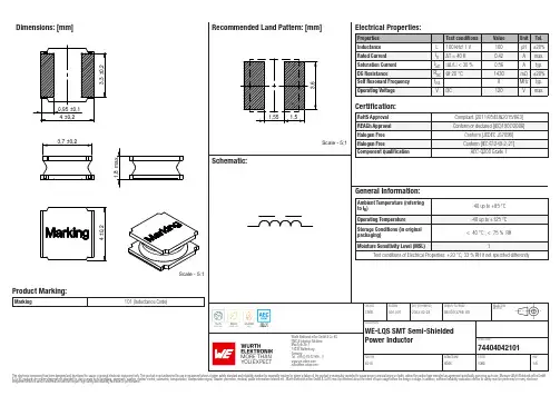
Dimensions: [mm]Scale - 5:1Product Marking:Marking101 (Inductance Code)7440404210174404042101BC74404042101T e m p e r a t u r eT pT L74404042101Cautions and Warnings:The following conditions apply to all goods within the product series of WE-LQS of Würth Elektronik eiSos GmbH & Co. KG:General:•This electronic component is designed and manufactured for use in general electronic equipment.•Würth Elektronik must be asked for written approval (following the PPAP procedure) before incorporating the components into any equipment in fields such as military, aerospace, aviation, nuclear control, submarine, transportation (automotive control, train control, ship control), transportation signal, disaster prevention, medical, public information network etc. where higher safety and reliability are especially required and/or if there is the possibility of direct damage or human injury.•Electronic components that will be used in safety-critical or high-reliability applications, should be pre-evaluated by the customer. •The component is designed and manufactured to be used within the datasheet specified values. If the usage and operation conditions specified in the datasheet are not met, the wire insulation may be damaged or dissolved.•Do not drop or impact the components, the component may be damaged.•Würth Elektronik products are qualified according to international standards, which are listed in each product reliability report. Würth Elektronik does not warrant any customer qualified product characteristics beyond Würth Elektroniks’ specifications, for its validity and sustainability over time.•The responsibility for the applicability of the customer specific products and use in a particular customer design is always within the authority of the customer. All technical specifications for standard products also apply to customer specific products.Product specific:Soldering:•The solder profile must comply with the technical product specifications. All other profiles will void the warranty.•All other soldering methods are at the customers’ own risk.•Strong forces which may affect the coplanarity of the components’ electrical connection with the PCB (i.e. pins), can damage the part, resulting in avoid of the warranty.Cleaning and Washing:•Washing agents used during the production to clean the customer application might damage or change the characteristics of the wire insulation, marking or plating. Washing agents may have a negative effect on the long-term functionality of the product.•Using a brush during the cleaning process may break the wire due to its small diameter. Therefore, we do not recommend using a brush during the PCB cleaning process.Potting:•If the product is potted in the customer application, the potting material may shrink or expand during and after hardening. Shrinking could lead to an incomplete seal, allowing contaminants into the core. Expansion could damage the components. We recommend a manual inspection after potting to avoid these effects.Storage Conditions:• A storage of Würth Elektronik products for longer than 12 months is not recommended. Within other effects, the terminals may suffer degradation, resulting in bad solderability. Therefore, all products shall be used within the period of 12 months based on the day of shipment.•Do not expose the components to direct sunlight.•The storage conditions in the original packaging are defined according to DIN EN 61760-2.•The storage conditions stated in the original packaging apply to the storage time and not to the transportation time of the components. Packaging:•The packaging specifications apply only to purchase orders comprising whole packaging units. If the ordered quantity exceeds or is lower than the specified packaging unit, packaging in accordance with the packaging specifications cannot be ensured. Handling:•Violation of the technical product specifications such as exceeding the nominal rated current will void the warranty.•Applying currents with audio-frequency signals may result in audible noise due to the magnetostrictive material properties.•The temperature rise of the component must be taken into consideration. The operating temperature is comprised of ambient temperature and temperature rise of the component.The operating temperature of the component shall not exceed the maximum temperature specified.These cautions and warnings comply with the state of the scientific and technical knowledge and are believed to be accurate and reliable.However, no responsibility is assumed for inaccuracies or incompleteness.Würth Elektronik eiSos GmbH & Co. KGEMC & Inductive SolutionsMax-Eyth-Str. 174638 WaldenburgGermanyCHECKED REVISION DATE (YYYY-MM-DD)GENERAL TOLERANCE PROJECTIONMETHODChriB001.0072023-02-28DIN ISO 2768-1mDESCRIPTIONWE-LQS SMT Semi-ShieldedPower Inductor ORDER CODE74404042101SIZE/TYPE BUSINESS UNIT STATUS PAGEImportant NotesThe following conditions apply to all goods within the product range of Würth Elektronik eiSos GmbH & Co. KG:1. General Customer ResponsibilitySome goods within the product range of Würth Elektronik eiSos GmbH & Co. KG contain statements regarding general suitability for certain application areas. These statements about suitability are based on our knowledge and experience of typical requirements concerning the areas, serve as general guidance and cannot be estimated as binding statements about the suitability for a customer application. The responsibility for the applicability and use in a particular customer design is always solely within the authority of the customer. Due to this fact it is up to the customer to evaluate, where appropriate to investigate and decide whether the device with the specific product characteristics described in the product specification is valid and suitable for the respective customer application or not.2. Customer Responsibility related to Specific, in particular Safety-Relevant ApplicationsIt has to be clearly pointed out that the possibility of a malfunction of electronic components or failure before the end of the usual lifetime cannot be completely eliminated in the current state of the art, even if the products are operated within the range of the specifications.In certain customer applications requiring a very high level of safety and especially in customer applications in which the malfunction or failure of an electronic component could endanger human life or health it must be ensured by most advanced technological aid of suitable design of the customer application that no injury or damage is caused to third parties in the event of malfunction or failure of an electronic component. Therefore, customer is cautioned to verify that data sheets are current before placing orders. The current data sheets can be downloaded at .3. Best Care and AttentionAny product-specific notes, cautions and warnings must be strictly observed. Any disregard will result in the loss of warranty.4. Customer Support for Product SpecificationsSome products within the product range may contain substances which are subject to restrictions in certain jurisdictions in order to serve specific technical requirements. Necessary information is available on request. In this case the field sales engineer or the internal sales person in charge should be contacted who will be happy to support in this matter.5. Product R&DDue to constant product improvement product specifications may change from time to time. As a standard reporting procedure of the Product Change Notification (PCN) according to the JEDEC-Standard inform about minor and major changes. In case of further queries regarding the PCN, the field sales engineer or the internal sales person in charge should be contacted. The basic responsibility of the customer as per Section 1 and 2 remains unaffected.6. Product Life CycleDue to technical progress and economical evaluation we also reserve the right to discontinue production and delivery of products. As a standard reporting procedure of the Product Termination Notification (PTN) according to the JEDEC-Standard we will inform at an early stage about inevitable product discontinuance. According to this we cannot guarantee that all products within our product range will always be available. Therefore it needs to be verified with the field sales engineer or the internal sales person in charge about the current product availability expectancy before or when the product for application design-in disposal is considered. The approach named above does not apply in the case of individual agreements deviating from the foregoing for customer-specific products.7. Property RightsAll the rights for contractual products produced by Würth Elektronik eiSos GmbH & Co. KG on the basis of ideas, development contracts as well as models or templates that are subject to copyright, patent or commercial protection supplied to the customer will remain with Würth Elektronik eiSos GmbH & Co. KG. Würth Elektronik eiSos GmbH & Co. KG does not warrant or represent that any license, either expressed or implied, is granted under any patent right, copyright, mask work right, or other intellectual property right relating to any combination, application, or process in which Würth Elektronik eiSos GmbH & Co. KG components or services are used.8. General Terms and ConditionsUnless otherwise agreed in individual contracts, all orders are subject to the current version of the “General Terms and Conditions of Würth Elektronik eiSos Group”, last version available at .Würth Elektronik eiSos GmbH & Co. KGEMC & Inductive SolutionsMax-Eyth-Str. 174638 WaldenburgGermanyCHECKED REVISION DATE (YYYY-MM-DD)GENERAL TOLERANCE PROJECTIONMETHODChriB001.0072023-02-28DIN ISO 2768-1mDESCRIPTIONWE-LQS SMT Semi-ShieldedPower Inductor ORDER CODE74404042101SIZE/TYPE BUSINESS UNIT STATUS PAGE。
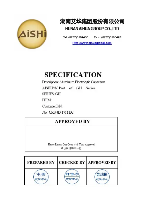
PREPARED BY CHECKED BY APPROVED BYSPECIFICATIONDescription: Aluminum Electrolytic Capacitors AISHI P/N: Part of GH Series SERIES: GH ITEM: Customer P/N: No.: CRS-JD-1711132APPROVED BYPlease Return One Copy with Your Approval承认后请寄回一份湖南艾华集团股份有限公司HUNAN AIHUA GROUP CO., L TDTel: (0737)6184466 Fax : (0737)6180493版本更改原因更改内容生效日期CRS-JD-1711132 新建新建 2017-11-11Customer 深圳市仁天芯科技有限公司SERIES GH DATE2017-11-11FIG-1TABLE-1No. CustomerPart No.AishiPart No.Capacitance(μF)Toleranceon RatedCapacitance(%)RatedV oltage(Vdc)SurgeV oltage(Vdc)OperatingTemp. Range(℃)tanδ(120Hz)(Max)LeakageCurrent(μA)(2min.)Max RippleCurrent (mArms)at105℃100kHzEnduranceat 105℃(Hours)Dimensions (mm)AppearanceDrawing No.ΦD Lαd F1 EGH1HM4R7D11OT4.7 ±205063-40~+105 0.14 3 35 5000 51120.5 2.0 FIG-12 EGH1HM100D11OT10 ±205063-40~+1050.145 50 500051120.5 2.0FIG-15 产品特性PRODUCT CHARACTERISTICS5.1电气特性ELECTRICAL CHARACTERISTICS序号 No. 项目 Item 测试方法 Test method性能 Performance5.1.1额定工作电压 Rated voltage电压:直流电压值+交流电压峰值≤额定电压 . Voltage :DC. Voltage + peak ripple voltage ≤ Rated voltage6.3V .DC~100V .DC5.1.2电容量 Capacitance测试频率:120Hz (±20%) 测试电路:串联等效测试电压:0.5Vrms 以下+1.5~ 2.0VDC Measuring frequency: 120Hz ±20% Measuring circuit:Series equivalent circuit Measuring voltage:0.5Vrms or less +1.5 to 2.0 VDC容量偏差:-20%~+20% Capacitance tolerance: -20%~+20%5.1.3 损失角正切值 Dissipation factor测试条件与5.1.2电容量测试相同 Testing conditions are the same as 5.1.2 for capacitanceDF 不大于规定值 DF: Not more than the specified value.5.1.4 漏电流 Leakage current在电容器两端施加额定工作电压,并串联1000±100Ω电阻,在施加电压2分钟后,测量漏电流。

2023.1根据客户需求进行系列的提案,开发的咨询商讨对应:各营业处根据客户具体设计构造进行专用产品的方案提供对应:工厂技术部在接到样品需求后进行快速响应。
并根据客户需要节奏提供参考报价对应:工厂技术部、各营业处除了技术响应以往,还会进行包括安全,物料等级登记等全面的技术支持对应:工厂技术部、质量保证部、各营业处根据客户需求对交货期进行灵活柔性管理,向客户提供高品质的产品对应:工厂生产部、各营业处Note: Please confirm product development details with your dealer.汽车应用总部邮编 604-0845 京都市中京区鸟丸通御池上电话 075-231-8461 传真 075-256-4158东京支店邮编 103-0026 东京都中央区日本桥托町14番9号 电话 03-3666-7811 传真 03-3666-7831名古屋支店邮编 460-0003 名古屋市中区锦2丁目4番3号 锦公园大楼18层电话 052-223-5581 传真 052-220-1839西日本支店邮编 604-0845 京都市中京区鸟丸通御池上电话 075-241-5370 传真 075-231-8467NICHICON (AMERICA ) CORP.927 East State Parkway, Schaumburg, Illinois 60173, U.S.A.TEL.1-847-843-7500 FAX.1-847-843-2798NICHICON (AUSTRIA ) GmbHBusinesspark Marximum, Modecenterstrasse 17, Unit 2-7-A, 1110 Vienna, AustriaTEL.43-1-706-7932 FAX.43-1-706-7933NICHICON (HONG KONG ) LTD.Unit 308, Harbour Centre Tower 1, 1 Hok Cheung Street,Hunghom, Kowloon, Hong KongTEL.852-2363-4331 FAX.852-2764-1867• THE REPRESENTATIVE OFFICEOF NICHICON (HONG KONG) LIMITED IN HANOI CITY Room 622, Floor 6, 59A Ly Thai To, Trang Tien Ward, Hoan Kiem District, Ha Noi, VietnamTEL.84-24-3936-7955 FAX.84-24-3936-8069NICHICON (SINGAPORE ) PTE. LTD.60 Paya Lebar Road, #11-17/18, Paya Lebar Square, Singapore 409051TEL.65-6481-5641 FAX.65-6481-6485NICHICON (TAIWAN ) CO., LTD.23F, No.68, Sec.5, Zhongxiao East. Road, Xinyi District, Taipei City 110, Taiwan, R.O.C.TEL.886-2-2722-2100 FAX.886-2-2722-2016NICHICON (THAILAND ) CO., LTD.1 Empire Tower, 15th Floor, Unit 1506, River Wing West,South Sathorn Road, Yannawa, Sathorn, Bangkok 10120 Thailand TEL.66-2-670-0150 FAX.66-2-670-0153NICHICON ELECTRONICS TRADING (SHANGHAI ) CO., LTD.Room 1206, Aetna Tower, 107 Zunyi Road, Shanghai, China 200051TEL.86-21-6237-5538 FAX.86-21-6237-5537• DALIAN BRANCH12F Senmao Building, 147 Zhongshan Road, Xigang District, Dalian, China 116011TEL.86-411-3989-3322 FAX.86-411-3989-3168NICHICON ELECTRONICS TRADING (SHENZHEN ) CO., LTD.Room A, 16/F, KK100No. 5016, Shen Nan Road East, Luo Hu District, Shenzhen, China 518001TEL.86-755-2294-1800 FAX.86-755-8294-5716• CHONGQING BRANCHRoom 2812, 28/F, International Trade Center (Part A), No.38, Qing Nian Road, Yuzhong District, Chongqing, China 400010 TEL.86-23-6310-8166 FAX.86-23-6310-8308• CHENGDU BRANCHRoom 1408, 14/F, Hailrun Complex (Part A), No.216, Xi Dong Da Street, Jinjiang District, Chengdu, Sichuan, China 610021 TEL.86-28-6212-9507 FAX.86-28-6212-9513NICHICON ELECTRONICS (INDIA ) PVT. LTD.Unit No.906, 9th Floor, Prestige Meridian-1, No.29 M.G. Road, Bengaluru 560001, Karnataka, IndiaTEL.91-80-4094-8661 FAX.91-80-4094-8651• DELHI OFFICEUnit No.407, 4th Floor, DLF Tower A, Jasola District Centre, New Delhi 110025, IndiaTEL.91-11-4254-8407 FAX.91-11-4254-8408• PUNE OFFICELevel 4, Prabhavee Tech Park, Baner, Pune 411045, India TEL.91-20-6723-5806 FAX.91-20-6723-6161NICHICON CORPORATION KOREA REPRESENTATIVE OFFICEB-1348, Heungdeok IT Valley, 13, Heungdeok1-ro, Giheung-gu, Yongin-si, Gyeonggi-do, 16954, KoreaTEL.82-31-8065-6366 FAX.82-31-8065-6367NICHICON (MALAYSIA ) SDN. BHD.No.4 Jalan P/10, Kawasan Perusahaan Bangi,43650 Bandar Baru Bangi, Selangor Darul Ehsan, Malaysia TEL.60-3-8925-0678 FAX.60-3-8925-0858NICHICON ELECTRONICS (WUXI ) CO., LTD.WUXI NICHICON ELECTRONICS R&D CENTER CO., LTD.Block 51-B, Wuxi National High & New Technology Industrial Development Zone, Wuxi, Jiangsu, China 214028TEL.86-510-8521-8222 FAX.86-510-8522-1170NICHICON ELECTRONICS (SUQIAN ) CO., LTD.No.18, Yangmingshan Avenue, Suzhou Suqian Industrial Park, Suqian, China 223800TEL.86-527-8097-8855 FAX.86-527-8286-8966尼吉康株式会社有关“C.A.S.E.”的市场需求 “C.A.S.E.“由梅赛德斯-奔驰于2016年提出,它展现了汽车行业未来的变革方向。
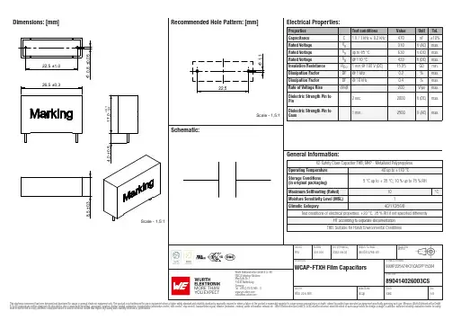
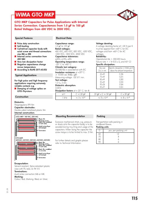
Dimensions: [mm]MXHP225474K310ACPP15004 890414026003CSMXHP225474K310ACPP15004 890414026003CSMXHP225474K310ACPP15004 890414026003CSMXHP225474K310ACPP15004 890414026003CST e m p e r a t u r eT T T MXHP225474K310ACPP15004890414026003CSCautions and Warnings:The following conditions apply to all goods within the product series of Film Capacitors of Würth Elektronik eiSos GmbH & Co. KG:General:•This electronic component is designed and manufactured for use in general electronic equipment.•Würth Elektronik must be asked for a written approval (following the certain PPAP level procedure) before incorporating the components into any equipment in the field such as military, aerospace, aviation, nuclear control, submarine, transportation (automotive control, train control, ship control), transportation signal, disaster prevention, medical, public information network etc. where higher safety and reliability are especially required and/or if there is the possibility of direct damage or human injury.•Electronic components that will be used in safety-critical or high-reliability applications, should be pre-evaluated by the customer. •Direct mechanical impact to the product shall be prevented as material of the body, pins or termination could flake or in the worst case it could break.•Avoid any water or heavy dust on capacitors surface, which may cause electrical leakage, damage, overheating or corrosion.•Würth Elektronik products are qualified according to international standards, which are listed in each product reliability report. Würth Elektronik does not warrant any customer qualified product characteristic, beyond Würth Elektronik specifications, for its validity and sustainability over time.•The customer is responsible for the functionality of his or her own products. All technical specifications for standard products also apply to customer specific products.•The component is designed and manufactured to be used within the datasheet specified values. If the usage and operation conditions specified in the datasheet are not met, the body, pins or termination may be damaged or dissolved.•Do not apply any kind of flexural or compressive force onto soldered or unsoldered component.•The capacitance tolerance as specified within the datasheet is only valid on the date of delivery and according specified measurement criteria.Product specificStorage conditions• A storage of Würth Elektronik products for longer than 12 months is not recommended. Within other effects, the terminals may suffer degradation, resulting in bad solderability. Therefore, all products shall be used within the period of 12 months based on the day of shipment.•Do not expose the components into direct sunlight.•The storage condition in the original packaging is defined according to DIN EN 61760-2.•The environment in which the capacitors are operated and stored has to have atmospheric characteristics and must be free of dew condensation and toxic gases (e.g. chlorine, ammonia, sulfur, hydrogen sulphide and hydrogen sulfate).•Do not expose the capacitor to environments with hazardous gas, ozone, ultraviolet rays or any kind of radiation. Avoid any contact of the capacitor with direct sunshine, saltwater, spray of water or types of oil during storage. •The storage conditions stated in the original packaging apply to the storage time and not to the transportation time of the components. Operating climatic conditions•Do not exceed the lower nor the upper specified temperature under no circumstances.•Do not use the capacitors under high humidity, high temperature or under high or low atmospheric pressure which may affect capacitors reliability.•Surface temperature including self-heating must be kept below the maximum operating temperature.Operating load conditions•Due to self-heating the reliability of the capacitor may be reduced, if high frequency AC or pulse is applied.•Consider carefully possible specific changes of electrical characteristics like capacitance over temperature, voltage and time as well as the specific performance over frequency for the actual use conditions.•Avoid any overvoltage and do not apply a continuous overvoltage. If an overvoltage is applied to the capacitor, the leakage current can increase drastically. The applied working voltage is not allowed to exceed the rated working voltage of the specific capacitor.•If film capacitors with safety approvals are operated with a DC voltage exceeding the specified AC voltage, the approvals given on the basis of IEC 60384-14 are no longer valid.Packaging:•The packaging specifications apply only to purchase orders comprising whole packaging units. If the ordered quantity exceeds or is lower than the specified packaging unit, packaging in accordance with the packaging specifications cannot be ensured. Soldering•The solder profile must comply with the Würth Elektronik technical soldering specification. All other profiles will void the warranty. •All other soldering methods are at the customer’s own risk.•Strong forces which may affect the coplanarity of the component’s electrical connection with the PCB (i.e. pins), can damage the part, resulting in void of the warranty.•Customer needs to ensure that the applied solder paste, the paste thickness and solder conditions are enough to guarantee a sufficient solder result according to the relevant criteria of IPC-A-610.•Excessive amount of solder may lead to higher tensile force and chip cracking. Insufficient amount of solder may detach the capacitor due to defective contacts.•Do not use excessive nor insufficient flux.Cleaning•Do not use any other cleaning solvents for box-typed capacitors except: ethanol, isopropanol, n-propanol - water mixtures. After cleaning a drying process with temperatures not exceeding 65°C and not longer than 4 hours is mandatory to prevent any kind ofelectrical damage.Würth Elektronik eiSos GmbH & Co. KGEMC & Inductive SolutionsMax-Eyth-Str. 174638 WaldenburgGermanyCHECKED REVISION DATE (YYYY-MM-DD)GENERAL TOLERANCE PROJECTIONMETHODFPu001.0012022-09-02DIN ISO 2768-1mDESCRIPTION TECHNICAL REFERENCEWCAP-FTXH Film Capacitors MXHP225474K310ACPP15004ORDER CODE890414026003CSSIZE/TYPE BUSINESS UNIT STATUS PAGECoating, molding and potting of the PCB•If the product is potted in the costumer’s application, the potting material might shrink or expand during and after hardening. Shrinking could lead to an incomplete seal, allowing contaminants into the body and termination. Expansion could damage the body or termination. We recommend a manual inspection after potting to avoid these effects.•If final assemblies will be placed completely in any plastic resin, physical, chemical and thermal influences must be considered. •When coating and molding the PCB, verify the quality influence on the capacitor.•Verify the curing temperature and assure that there is no harmful decomposing or reaction gas emission during curing. •Do not exceed the specified max. self-heating.Vibration resistance•Do not exceed the vibration limits given by IEC60068-2-6.Handling•After soldering, please pay attention not to bend, twist or distort the PCB in handling and storage. •Avoid excessive pressure during the functional check of the PCB. •Avoid bending stress while breaking the PCB.•WCAP-FTXX and WCAP-FTX2 capacitors are not designed and not recommended to be used in series connection to the mains. •The temperature rise of the component must be taken into consideration. The operating temperature is comprised of ambient temperature and temperature rise of the component.The operating temperature of the component shall not exceed the maximum temperature specified.Flammability•Avoid any external energy or open fire (passive flammability).These cautions and warnings comply with the state of the scientific and technical knowledge and are believed to be accurate and reliable.However, no responsibility is assumed for inaccuracies or incompleteness.(V2.2)Würth Elektronik eiSos GmbH & Co. KG EMC & Inductive Solutions Max-Eyth-Str. 174638 Waldenburg GermanyCHECKED REVISION DATE (YYYY-MM-DD)GENERAL TOLERANCEPROJECTION METHODFPu001.0012022-09-02DIN ISO 2768-1mDESCRIPTIONTECHNICAL REFERENCEWCAP-FTXH Film CapacitorsMXHP225474K310ACPP15004ORDER CODE890414026003CSSIZE/TYPEBUSINESS UNITSTATUSPAGEImportant NotesThe following conditions apply to all goods within the product range of Würth Elektronik eiSos GmbH & Co. KG:1. General Customer ResponsibilitySome goods within the product range of Würth Elektronik eiSos GmbH & Co. KG contain statements regarding general suitability for certain application areas. These statements about suitability are based on our knowledge and experience of typical requirements concerning the areas, serve as general guidance and cannot be estimated as binding statements about the suitability for a customer application. The responsibility for the applicability and use in a particular customer design is always solely within the authority of the customer. Due to this fact it is up to the customer to evaluate, where appropriate to investigate and decide whether the device with the specific product characteristics described in the product specification is valid and suitable for the respective customer application or not.2. Customer Responsibility related to Specific, in particular Safety-Relevant ApplicationsIt has to be clearly pointed out that the possibility of a malfunction of electronic components or failure before the end of the usual lifetime cannot be completely eliminated in the current state of the art, even if the products are operated within the range of the specifications.In certain customer applications requiring a very high level of safety and especially in customer applications in which the malfunction or failure of an electronic component could endanger human life or health it must be ensured by most advanced technological aid of suitable design of the customer application that no injury or damage is caused to third parties in the event of malfunction or failure of an electronic component. Therefore, customer is cautioned to verify that data sheets are current before placing orders. The current data sheets can be downloaded at .3. Best Care and AttentionAny product-specific notes, cautions and warnings must be strictly observed. Any disregard will result in the loss of warranty.4. Customer Support for Product SpecificationsSome products within the product range may contain substances which are subject to restrictions in certain jurisdictions in order to serve specific technical requirements. Necessary information is available on request. In this case the field sales engineer or the internal sales person in charge should be contacted who will be happy to support in this matter.5. Product R&DDue to constant product improvement product specifications may change from time to time. As a standard reporting procedure of the Product Change Notification (PCN) according to the JEDEC-Standard inform about minor and major changes. In case of further queries regarding the PCN, the field sales engineer or the internal sales person in charge should be contacted. The basic responsibility of the customer as per Section 1 and 2 remains unaffected.6. Product Life CycleDue to technical progress and economical evaluation we also reserve the right to discontinue production and delivery of products. As a standard reporting procedure of the Product Termination Notification (PTN) according to the JEDEC-Standard we will inform at an early stage about inevitable product discontinuance. According to this we cannot guarantee that all products within our product range will always be available. Therefore it needs to be verified with the field sales engineer or the internal sales person in charge about the current product availability expectancy before or when the product for application design-in disposal is considered. The approach named above does not apply in the case of individual agreements deviating from the foregoing for customer-specific products.7. Property RightsAll the rights for contractual products produced by Würth Elektronik eiSos GmbH & Co. KG on the basis of ideas, development contracts as well as models or templates that are subject to copyright, patent or commercial protection supplied to the customer will remain with Würth Elektronik eiSos GmbH & Co. KG. Würth Elektronik eiSos GmbH & Co. KG does not warrant or represent that any license, either expressed or implied, is granted under any patent right, copyright, mask work right, or other intellectual property right relating to any combination, application, or process in which Würth Elektronik eiSos GmbH & Co. KG components or services are used.8. General Terms and ConditionsUnless otherwise agreed in individual contracts, all orders are subject to the current version of the “General Terms and Conditions of Würth Elektronik eiSos Group”, last version available at .Würth Elektronik eiSos GmbH & Co. KGEMC & Inductive SolutionsMax-Eyth-Str. 174638 WaldenburgGermanyCHECKED REVISION DATE (YYYY-MM-DD)GENERAL TOLERANCE PROJECTIONMETHODFPu001.0012022-09-02DIN ISO 2768-1mDESCRIPTION TECHNICAL REFERENCEWCAP-FTXH Film Capacitors MXHP225474K310ACPP15004ORDER CODE890414026003CSSIZE/TYPE BUSINESS UNIT STATUS PAGE。
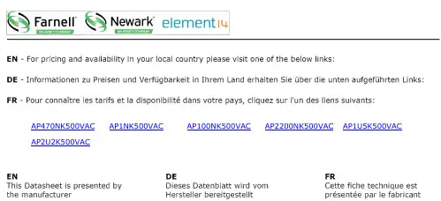
AP470NK500VAC AP1NK500VAC AP100NK500VAC AP2200NK500VAC AP1U5K500VAC AP2U2K500VACICW:Product guide:Radials:RNRT/RNRPFILM CAPACITORS Axials:AC Voltage ratedAX:Polypropylene250Vac ratedAP:Polypropylene500Vac&660Vac ratedPolypropylene axial wrap and end seal style capacitors offeringlow loss characteristics.Ideally suited to applications such asmains filters and where pulse performance is important.ICW:Product guide:Axials:AC Voltage rated:AX/APFILM CAPACITORS Full text descriptionBoth of these capacitors are constructed using the familiar‘wrap and end seal’method-wrapping the wound elements with heavy duty electrical tape which is wider than the elementand sealing the cavities formed at each end with epoxy resin.This style of manufacture resultsin a cost effective and volumetrically efficient component of the highest quality.The AX capacitors are suitable for pulse type circuits where high peak current handlingcapability is essential or at high frequency ac voltages where low loss is of prime consideration.The higher voltage handling capabilities of the AP range makes them ideally suited toapplications such as mains filtering and higher voltage pulse applications.Capacitance range AX:100nF to2µ2FAP:10nF to2µ2FT olerance±10%standard.Others by request Dissipation factor≤0.001@1KHz&20±3°CI nsulation resistance≥104MΩ-µF(C>330nF),≥3x10⁴MΩ(C≤330nF)@250Vac for AX and500Vdcfor AP and20±3°CRated voltage AX:250VacAP:500and660VacPulse performance See table.Ratings assume linear changeto/from rated voltage T emperature range-55to+100°CEnvironmental category55/100/56to EN60068-1(IEC68-1)Proof voltage test 1.5x rated voltage for30s.Not to be repeated Solderability BS2011:Part2.1T(IEC68-2-20)Solder Globule Method of test T aVibration EN60068-2-6(IEC68-2-6)T est Fc10to500Hz0.75mm or98m/s2 Bump EN60068-2-29(IEC68-2-29)T est Eb390m/s21000±10bumpsT echnical detailsICW:Product guide:Axials:AC Voltage rated:AX/APFILM CAPACITORSCAP(µF) 0.01 0.015 0.022 0.033 0.047 0.0680.1 0.15 0.22 0.33 0.470.681.001.52.2AX:250Vac/400VdcAP:500Vac/1000VdcAP:660Vac/1500VdcSize chart:Axials:AX&APAX Range:T erminations are tinned copper clad steel with a minimum length of30mmICW :Product guide :Axials :AC Voltage rated :AX /APFILM CAPACITORSPulse performanceRated voltage (Vdc)Body length250V 500V 660V (mm)AXAPAP191502910080100465070Maximum rates of change of Voltage dV/dt (V/µSFigures quoted in the chart above assume linear charge/discharge to /from rated voltage.When applied voltage (V A )is less than the rated voltage (V R )the rating may be increased by a factor V R /V A .OutlinedimensionsICW:Product guide:Axials:AC Voltage rated:AX/APFILM CAPACITORSAX100nK250VAX2µ2K250VCap Value µF for C≥IµF nF for C<IµFT oleranceM=±20%K=±10%J=±5%G=±2%†F=±1%†RatedVoltage acAP150nJ 660VAP2µ2K500VCap ValueµF for C≥IµFnF for C<IµFT oleranceM=±20%K=±10%J=±5%G=±2%†F=±1%†Rated Voltage ac†subject to availabilityOrdering detailsContact detailsIndustrial Capacitors(Wrexham)LtdMiners Road Llay Wrexham North Wales LL120PJT elephone44(0)1978853805Facsimile44(0)1978853785 Web Email***************.ukAP470NK500VAC AP1NK500VAC AP100NK500VAC AP2200NK500VAC AP1U5K500VAC AP2U2K500VAC。

AAM型滤波电容器使用说明书杭州银湖电气有限企业本说明书合用于频次50赫兹沟通电力系统提升功率因数用的并联电容器(以下简称电容器)1、产品型号命名及表表示义A □M □—□—□W户外式(户内式不用字母表示)相数(1表示单相,3表示三相)额定容量(千乏,kvar)额定电压(千伏,kV)全薄膜介质浸渍剂[F表示二芳基乙烷,A表示苄基甲苯]滤波电容器比如:AFM11/√3—100—1W。
表示:滤波电容器,二芳基乙烷浸渍全膜介质,额定电压为11/√3千伏,额定容量为100千乏,单相,户外式。
2、构造电容器由箱壳和芯子构成,箱壳用薄钢板密封焊接制成。
箱壳盖上焊有出线瓷套,箱壁两侧焊有供安装用的吊攀,一侧吊攀上装有接地螺栓。
电容器芯子由若干个元件和绝缘件迭压构成。
元件用电容器膜作为介质,铝箔作极板卷制构成。
为适应各样电压,在芯子中元件接成并联或串连,依据用户需要可在电容器内部装有放电电阻。
千伏及以上的电容器每台可装备独自的外装熔断器。
3、技术数据所有系列电容器装置于一般天气条件,在环境温度-50℃~+55℃,海拔高度不超出1000米的地域使用。
电容器的实测电容与额定值的偏差不超出标准值的+10%~-5%。
电容器在工频沟通的额定电压下,温度为20℃时的消耗角正切(tgδ)值应切合表1。
凡内部装有放电电阻的电容器消耗角正切值同意增大。
电容器及电容器元件的工频稳态过电压和相应的运转时间应切合表2。
为了延伸电容器的使用寿命,电容器应常常保持在不超出额定电压下运转。
电容器应能蒙受第一个峰值电压不超出2√2U n连续1/2周波的过渡过电压。
电容器同意在因为电压高升及高次谐波惹起的不超出的稳态过电流下长久运转。
关于电容量有最大正偏差的电容器,这类过电流同意达到。
为了延伸电容器的使用寿命,电容器应保持在额定电流下运转。
电容器应能蒙受100倍电容器额定电流的涌流冲击,每年这样的涌流冲击不超出1000次,此中若干次是在电容器内部温度低于0℃与下限温度之间发生的。
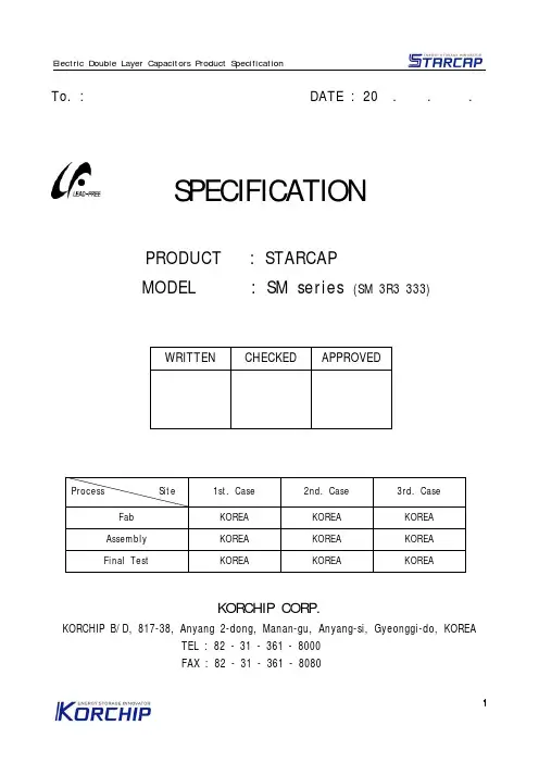
WRITTEN CHECKED APPROVEDProcess Site1st. Case 2nd. Case 3rd. Case Fab KOREA KOREA KOREA Assembly KOREA KOREA KOREA Final TestKOREAKOREAKOREATo. : DATE : 20 . . .SPECIFICATIONPRODUCT : STARCAPMODEL : SM series (SM 3R3 333)KORCHIP CORP.KORCHIP B/D, 817-38, Anyang 2-dong, Manan-gu, Anyang-si, Gyeonggi-do, KOREA TEL : 82 - 31 - 361 - 8000 FAX : 82 - 31 - 361 - 8080Page No.ITEM etc.1Cover Page2Index3 Revision History4 1. Scope2. Part Number System3. Product Model Name4. Photo5. Nominal Specifications5 6. Cell Structure6-7 7. Product Construction And Dimension8-9 8. Carrier Tape Construction And Dimension10 9. Specifications And Test Method11 10. Measuring Method Of Characteristics12 11. Reflow Soldering12. Manual Soldering13 13. Cautions For Use14 14. Environmental ManagementIndexNo.Documentation Check Description of Revision Approval Date1Byong-il Lim(R&D)(Q.A.)Initial Release for StandardSpecificationsMun-BaeLee(CTO)Mar. 1,2011 Revision HistoryManufacturer InformationManufacturer: Korchip CorporationLocation: KORCHIP B/D, 817-38, Anyang 2-dong, Manan-gu, Anyang-si, Gyeonggi-do, KOREATel.: +82-31-361-8000Fax.: +82-31-361-8080Items SM 3R3 333Cell SizeØ3.8 × 1.1mm OPERATING TEMPERATURE-25 ~ +60 ℃RATED VOLTAGE3.3 VDC ELECTROSTATIC CAPACITANCE (F)0.033 FCAPACITANCE (mAh)13.8 uAh (3.0V-1.5V)CAPACITANCE TOLERANCE -20 ~ 80 %EQUIVALENT SERIES RESISTANCE (ESR)LESS THAN 200ΩLEAKAGE CURRENT (LC)LESS THAN 100㎂1. ScopeThis specification applies to STARCAP(Electric Double Layer Capacitor), submitted to specified customer in cover page.2. Part Number SystemSM 3R3 333 T01 (Example) ① ② ③ ④① Series Name② Rated Voltage : 3.3VDC③ Capacitance : 0.033 F (333 = 33 × 10+3uF) ④ Terminal Type : T01-type3. Product Model Name1) Product : Electric Double Layer Capacitor 2) Model name : SM3R3333 T01, H014. Photo (by terminal type)T01 H015. Nominal Specifications6. Cell Structure7. Product Construction And Dimension (T erminal T ype : T01)7. Product Construction And Dimension (T erminal T ype : H01)8. Carrier T ape Construction And Dimension (T erminal T ype : T01)8. Carrier T ape Construction And Dimension (T erminal T ype : H01)9. Specifications And Test Method10. Measuring Method Of CharacteristicsE0 : VdcR C : 100Ω11. Reflow SolderingExcessive heat stress may result in the deterioration of the electrical characteristics of the capacitor, loss of air tightness, and electrolyte leakage due to the rise in internal pressure.Use the general reference chart then set soldering temperature and time.Max. 260℃ (within 5 seconds)The time of repeated reflow soldering must be two time or less.Do not use reflow soldering when the cell voltage is above 0.3V.12. Manual SolderingFor use of a soldering iron, it should not touch the cell body.Temperature of the soldering iron should be less than 350℃.Soldering time for terminals should be less than 3 seconds.13. Cautions For UsePlease be careful for following points when you use STARCAP.1) Do not apply more than rated voltage.If you apply more than rated voltage, STARCAP's electrolyte will be electrolyzed and itsESR increase. At the worst, it may be broken.2) Do not use STARCAP for ripple absorption.3) PolarityThe STARCAP is non-polar fundamentally, however STARCAP gets polarity throughaging process before it is packed. Please mount it in accordance with its polarity to maintain the best condition.4) Operating temperature and lifeGenerally, STARCAP has a lower leakage current, longer back-up time and longer life in the low temperature i.e. the room temperature. But it has a higher leakage current, shorter back-up time and shorter life in the high temperature.Please design to keep STARCAP away from calorific parts.5) CleaningSome detergent or high temperature drying causes deterioration of STARCAP.If you wash STARCAP, Consult us.6) Following figure shows the general back-up circuit.D : Diode to prevent the reverse currentR : Resistor to control the chargingcurrentSeriesRoHS directive Pb, Cr+6, Hg, Cd, PBB,PBDE ELV directive Pb, Cr+6, Hg, Cd PVC etc.SMN.D.N.D.N.D. 7) Short-circuit STARCAPYou can short-circuit between terminals of STARCAP without resistor. However when you short-circuit frequently, please consult us.8) StorageIn long term storage, please store STARCAP in following condition;① TEMP. : 15 ~ 35 ℃② HUMIDITY : 45 ~ 75 %RH③ NON-DUST ENVIRONMENT9) Do not disassemble STARCAP. It contains electrolyte.10) Series connection of STARCAPOver-rated voltage may be applied to a single STARCAP in series connection due to the deviation of capacitance and ESR of each STARCAP. Please inform us if you are using STARCAP in series connection and please design so as not to apply over-rated voltage to each STARCAP, and use STARCAPs from same lot.11) The tips of STARCAP terminals are very sharp. Please handle with care.14. Environmental ManagementAll STARCAP products are RoHS compliant and environment friendly.By changing the solder plating from leaded solder to lead-free solder, our new STARCAP has became even more friendly to the environment.* N.D. : Not detected。
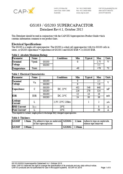
Unit 9, 12 Mars Rd Tel: +61 2 9420 0690 CAP-XX (Australia) Pty LtdLane Cove NSW 2066 Fax: +61 2 9420 0692 ABN 28 077 060 872Australia ACN 077 060 872 GS103 / GS203 SUPERCAPACITORDatasheet Rev4.1, October 2015This Datasheet should be read in conjunction with the CAP-XX Supercapacitors Product Guide whichcontains information common to our product lines.Electrical SpecificationsThe GS103 is a single cell supercapacitor. The GS203 is a dual cell supercapacitor with two GS103 cells in series, so GS203 capacitance = Capacitance of GS103/2 and GS203 ESR = 2 x GS103 ESR.Definition of TermsIn its simplest form, the Equivalent Series Resistance (ESR) of a capacitor is the real part of the complex impedance. In the time domain, it can be found by applying a step discharge current to a charged cell as in Fig. 1. In this figure, the supercapacitor is pre-charged and then discharged with a current pulse, I =1A for duration 0.01 sec.Figure 1: Effective capacitance, instantaneous capacitance and ESR for a GS203The ESR is found by dividing the instantaneous voltage step (∆V) by I. In this example = (4.5V - 4.47V)/1A = 30mΩ.The instantaneous capacitance (C i) can be found by taking the inverse of the derivative of the voltage, and multiplying it by I.The effective capacitance for a pulse of duration ∆t n, Ce(∆t n) is found by dividing the total charge removed from the capacitor (∆Q n) by the voltage lost by the capacitor (∆V n). For constant current Ce(∆t n) = I x∆t n/∆V n. Ce increases as the pulse width increases and tends to the DC capacitance value as the pulse width becomes very long (~10 secs). After 2msecs, Fig 1 shows the voltage drop V2ms = (4.47 V – 4.45V) = 20mV. Therefore Ce(2ms) = 1A x 2ms/20mV = 100mF. After 10ms, the voltage drop = 4.47 V – 4.42V = 50mV. Therefore Ce(10ms) = 1 A x 10ms/50mV = 200mF. The DC capacitance of a GS203 = 0.27 F. Note that∆V, or IR drop, is not included because very little charge is removed from the capacitor during this time. C e shows the time response of the capacitor and it is useful for predicting circuit behavior in pulsed applications.Measurement of DC CapacitanceFig 2: Measurement of DC Capacitance for a GS203Fig 2 shows the measurement of DC capacitance by drawing a constant 100mA current from a fully charged supercapacitor and measuring the time taken to discharge from 1.5V to 0.5V for a single cell, or from 3V to 1V for a dual cell supercapacitor. In this case, C = 0.1A x 5.8s /2V = 290mF, which is well within the 270mF +/- 20% tolerance for a GS203 cell.Measurement of ESRFig 3: Measurement of ESR for a GS203Fig 3 shows DC measurement of ESR by applying a step load current to the supercapacitor and measuring the resulting voltage drop. CAP-XX waits for a delay of 50µs after the step current is applied to ensure the voltage and current have settled. In this case the ESR is measured as 30mV/1A = 30mΩ.Effective CapacitanceFigure 4: Effective CapacitanceFig 4 shows the effective capacitance for the GS103, GS203 @ 23°C. This shows that for a 1msec PW, you will measure 29% of DC capacitance or 156.6mF for a GS103 or 78.3mF for a GS203. At 10msecs you will measure 65% of the DC capacitance, and at 100msecs you will measure 87% of DC capacitance. Ceffective is a time domain representation of the supercapacitor's frequency response. If, for example, you were calculating the voltage drop if the supercapacitor was supporting 1A for 10msecs, then you would use the Ceff(10msecs) = 29% of DC capacitance = 78.3mF for a GS203, so Vdrop = 1A x ESR + 1A x duration/C = 1A x 140mΩ + 1A x 10ms / 78.3mF = 87mV. The next section on pulse response shows how the effective capacitance is sufficient for even short pulse widths.Pulse ResponseFig 5 shows that the GS203supercapacitor does anexcellent job supporting aGPRS class 10 pulse train,drawing 1.8A for 1.1ms at25% duty cycle. The source iscurrent limited to 0.6A and thesupercapacitor provides the1.2A difference to achieve thepeak current. At first glancethe freq response of Fig 8indicates the supercapacacitorwould not support a 1ms pulse,but the Ceff of 78.3mFcoupled with the low ESRsupports this pulse train withonly ~70mV droop in thesupply rail.Fig 5: GS203 Pulse Response with GPRS Class 10 Pulse TrainDC Capacitance variation with temperatureFigure 6: Capacitance change with temperatureFig 6 shows that DC capacitance is approximately constant with temperature.ESR variation with temperatureFigure 7: ESR change with temperatureFig 7 shows that ESR at -40°C is ~2 x ESR at room temp, and that ESR at 70ºC is ~0.8 x ESR at room temperature.Frequency ResponseFig 8: Frequency Response of Impedance (biased at 2.3V with a 50mV test signal)Fig 9: Frequency Response of ESR, Capacitance & InductanceFig 8 shows the supercapacitor behaves as an ideal capacitor until approx 10 Hz when the magnitude no longer rolls off proportionally to 1/freq and the phase crosses -45°. Performance of supercapacitors with frequency is complex and the best predictor of performance is Fig 4 showing effective capacitance as a function of pulsewidth.Leakage CurrentFig 10: Leakage CurrentFig 10 shows the leakage current for GS103 at room temperature. The leakage current decays over time, and the equilibrium value leakage current will be reached after ~120hrs at room temperature. The typical equilibrium leakage current is 1µA at room temperature. At 70°C leakage current will be ~10µA. Charge CurrentFig 11: Charging a GS103 with low currentThe corollary to the slow decay in leakage currents shown in Fig 10 is that charging a supercapacitor at very low currents takes longer than theory predicts. At higher charge currents, the charge rate is as theory predicts. For example, it should take 0.54F x 2.2V / 0.00002A = 18hrs to charge a 0.54 F supercapacitor to 2.2V at20µA, but Fig 11 shows it took 32hrs. At 100µA charging occurs at a rate close to the theoretical rate.RMS CurrentFig 12: Temperature rise in GS203 with RMS currentContinuous current flow into/out of the supercap will cause self heating, which limits the maximum continuous current the supercapacitor can handle. This is measured by a current square wave with 50% duty cycle, charging the supercapacitor to rated voltage at a constant current, then discharging the supercapacitor to half rated voltage at the same constant current value. For a square wave with 50% duty cycle, the RMS current is the same as the current amplitude. Fig 12 shows the increase in temperature as a function of RMS current. From this, the maximum RMS current in an application can be calculated, for example, if the ambient temperature is 40︒C, and the maximum desired temperature for the supercapacitor is 70︒C, then the maximum RMS current should be limited to 6A, which causes a 30︒C temperature increase.CAP-XX Supercapacitors Product GuideRefer to the package drawings in the CAP-XX Supercapacitors Product Guide for detailed information of the product’s dimensions, PCB landing placements, active areas and electrical connections.Refer to the CAP-XX Supercapacitors Product Guide for information on endurance and shelf life, transportation and storage, assembly and soldering, safety and RoHS/EREACH certification.。
PMC-651C电容器保护测控装置操作使用说明书(V1.6版)深圳市中电电力技术有限公司2010年5月5日PMC-651C电容器保护测控装置深圳市中电电力技术有限公司目录1装置简介 (1)1.1概述 (1)1.2产品特点 (1)1.3基本功能 (1)2技术指标 (2)2.1工作环境条件 (2)2.2额定参数 (2)2.3准确度 (2)2.4遥信分辨率 (3)2.5过载能力 (3)2.6继电器输出 (3)2.7开关量输入 (3)2.8电气绝缘性能 (3)2.9机械性能 (4)2.10电磁兼容性能 (4)3功能说明 (5)3.1保护功能 (5)3.1.1瞬时电流速断 (5)3.1.2限时电流速断 (5)3.1.3定时限过流 (5)3.1.4过负荷保护 (5)3.1.5电流不平衡 (5)3.1.6过电压保护 (6)3.1.7失压保护 (6)3.1.8差压保护 (6)3.1.9差流保护 (6)3.1.10零序过流 (6)3.1.11TV断线 (7)3.1.12控制回路异常 (7)3.2开入量配置 (7)3.3测量监视功能 (8)3.3.1测量数据 (8)3.3.2保护数据 (8)3.3.3计量数据 (8)3.3.4遥信功能 (8)3.3.5AI/AO (9)3.4控制功能 (9)3.5通讯功能 (10)3.6记录功能 (10)3.6.1事件记录 (10)I3.6.2故障录波记录 (11)3.7谐波分析功能 (11)3.8对时功能 (12)4操作使用说明 (12)4.1按键操作 (12)4.2信号指示灯 (12)4.3装置上电 (13)4.4默认显示 (13)4.5事件报告显示 (13)4.6显示说明 (13)4.6.1数据查询 (14)4.6.2定值查询 (14)4.6.3定值管理 (14)4.6.4报告管理 (17)4.6.5谐波分析 (18)4.6.6装置维护 (19)4.6.7装置调试 (19)4.6.8定值清单 (19)5安装调试说明 (22)5.1安装 (22)5.1.1装置安装图 (22)5.1.2背板端子布置 (23)5.2通电试验 (26)5.3投运前调试 (26)5.4装置故障分析 (26)6接线原理图 (28)6.1装置接线原理图 (28)6.2操作回路原理图 (30)7售后服务承诺 (32)7.1装置升级 (32)7.2质保范围 (32)8附录1:手册变更信息 (33)0IIPMC-651C电容器保护测控装置深圳市中电电力技术有限公司1装置简介1.1概述PMC-651C是深圳市中电电力技术有限公司精心开发适用于补偿电容器组的保护测控装置。
ContactorsCA4-12-01-*CA8-12-01-*Contactor Mini, FVNR 12A, 3-Pole, AC Coil, 1NC AuxCA4-12-10-*CA8-12-10-*Contactor Mini, FVNR 12A, 3-Pole, AC Coil, 1NO AuxCA4-12C-01-*D CA8-12C-01-*Contactor Mini, FVNR 12A, 3-Pole, 24VDC Coil, 1NC AuxCA8-12C-01-24DD Contactor Mini, FVNR 12A, 3-Pole, 24VDC Coil w/Diode, 1NC AuxCA4-12C-10-*D CA8-12C-10-*D Contactor Mini, FVNR 12A, 3-Pole, 24VDC Coil, 1NO AuxCA8-12C-10-24DD Contactor Mini, FVNR 12A, 3-Pole, 24VDC Coil w/Diode, 1NO AuxCA4-9-01-*CA8-9-01-*Contactor Mini, FVNR 9A, 3-Pole, AC Coil, 1NC AuxCA4-9-10-*CA8-9-10-*Contactor Mini, FVNR 9A, 3-Pole, AC Coil, 1NO AuxCA4-9C-01-*D CA8-9C-01-*D Contactor Mini, FVNR 9A, 3-Pole, 24VDC Coil, 1NC AuxCA8-9C-01-24DD Contactor Mini, FVNR 9A, 3-Pole, 24VDC Coil w/Diode, 1NC AuxCA4-9C-10-*D CA8-9C-10-*D Contactor Mini, FVNR 9A, 3-Pole, 24VDC Coil, 1NO AuxCA8-9C-10-24DD Contactor Mini, FVNR 9A, 3-Pole, 24VDC Coil w/Diode, 1NO AuxCA8-12C-M22-*D Contactor Mini, FVNR 12A, 4-Pole 2NO 2NC, 24VDC CoilCA8-12C-M22-24DD Contactor Mini, FVNR 12A, 4-Pole 2NO 2NC, 24VDC Coil w/DiodeCA8-12C-M31-*D Contactor Mini, FVNR 12A, 4-Pole 3NO 1NC, 24VDC CoilCA8-12C-M31-24DD Contactor Mini, FVNR 12A, 4-Pole 3NO 1NC, 24VDC Coil w/DiodeCA8-12C-M40-*D Contactor Mini, FVNR 12A, 4-Pole 4NO, 24VDC CoilCA8-12C-M40-24DD Contactor Mini, FVNR 12A, 4-Pole 4NO, 24VDC Coil w/DiodeCA8-12-M22-*Contactor Mini, FVNR 12A, 4-Pole 2NO 2NC, AC CoilCA8-12-M31-*Contactor Mini, FVNR 12A, 4-Pole 3NO 1NC, AC CoilCA8-12-M40-*Contactor Mini, FVNR 12A, 4-Pole 4NO, AC CoilCA8-9C-M22-*D Contactor Mini, FVNR 9A, 4-Pole 2NO 2NC, 24VDC CoilCA8-9C-M22-24DD Contactor Mini, FVNR 9A, 4-Pole 2NO 2NC, 24VDC Coil w/DiodeCA8-9C-M31-*D Contactor Mini, FVNR 9A, 4-Pole 3NO 1NC, 24VDC Coil,CA8-9C-M31-24DD Contactor Mini, FVNR 9A, 4-Pole 3NO 1NC, 24VDC Coil w/DiodeCA4-9C-M40-*D CA8-9C-M40-*D Contactor Mini, FVNR 9A, 4-Pole 4NO, 24VDC CoilCA8-9C-M40-24DD Contactor Mini, FVNR 9A, 4-Pole 4NO, 24VDC Coil w/DiodeCA8-9-M22-*Contactor Mini, FVNR 9A, 4-Pole 2NO 2NC, AC CoilCA8-9-M31-*Contactor Mini, FVNR 9A, 4-Pole 3NO 1NC, AC CoilCA4-9-M40-*CA8-9-M40-*Contactor Mini, FVNR 9A, 4-Pole 4NO, AC CoilCAU4-12-02-*-LW CAU8-12-02-*-LW Contactor Mini, FVR 12A, 3-Pole, AC Coil, Less Wiring, 2NC AuxCAU4-12-42-*-PW CAU8-12-42-*-PW Contactor Mini, FVR 12A, 3-Pole, AC Coil, w/Pwr Wiring, 2NO 1NC AuxCAU8-12C-02-24DD-LW Contactor Mini, FVR 12A, 3-Pole, 24VDC Coil w/Diode, Less Wiring, 2NC AuxCAU8-12C-02-*D-LW Contactor Mini, FVR 12A, 3-Pole, 24VDC Coil, Less Wiring, 2NC AuxCAU8-12C-42-24DD-PW Contactor Mini, FVR 12A, 3-Pole, 24VDC Coil w/Diode, w/Pwr Wiring, 2NO 2NC AuxCAU8-12C-42-*D-PW Contactor Mini, FVR 12A, 3-Pole, 24VDC Coil, w/Pwr Wiring, 2NO 2NC Aux CAU4-9-02-*-LW CAU8-9-02-*-LW Contactor Mini, FVR 9A, 3-Pole, AC Coil, Less Wiring, 2NC AuxCAU4-9-42-*-PW CAU8-9-42-*-PW Contactor Mini, FVR 9A, 3-Pole, AC Coil, w/Pwr Wiring, 2NO 2NC AuxCAU8-9C-02-24DD-LW Contactor Mini, FVR 9A, 3-Pole, 24VDC Coil w/Diode, Less Wiring, 2NC AuxCAU8-9C-02-*D-LW Contactor Mini, FVR 9A, 3-Pole, 24VDC Coil, Less Wiring, 2NC AuxCAU8-9C-42-24DD-PW Contactor Mini, FVR 9A, 3-Pole, 24VDC Coil w/Diode, w/Pwr Wiring, 2NO 2NC AuxCAU8-9C-42-*D-PW Contactor Mini, FVR 9A, 3-Pole, 24VDC Coil, w/Pwr Wiring, 2NO 2NC Aux CAT4-12-01-*-#CAT8-12-01-*-#Starter Mini, FVNR 12A, AC Coil, 1NC AuxCAT4-12-10-*-#CAT8-12-10-*-#Starter Mini, FVNR 12A, AC Coil, 1NO AuxCAT4-9-01-*-#CAT8-9-01-*-#Starter Mini, FVNR 9A, AC Coil, 1NC AuxCAT4-9-10-*-#CAT8-9-10-*-#Starter Mini, FVNR 9A, AC Coil, 1NO AuxCAT4-9-10-120-#CAT8-9-10-120-#Starter Mini, FVNR 9A, 120VAC Coil, 1NO AuxCAT4-9C-01-*D-#CAT8-9C-01-*D-#Starter Mini, FVNR 9A, 24VDC Coil, 1NC AuxCAT8-9C-01-24DD-#Starter Mini, FVNR 9A, 24VDC Coil w/Diode, 1NC AuxCAT4-9C-10-*D-#CAT8-9C-10-*D-#Starter Mini, FVNR 9A, 24VDC Coil, 1NO AuxCAT8-9C-10-24DD-#Starter Mini, FVNR 9A, 24VDC Coil w/Diode, 1NO AuxCAUT4-12-02-*-#-LW CAUT8-12-02-*-#-LW Starter Mini, FVR 12A, AC Coil, O/L, Less Wiring, 2NC AuxCAUT4-12-42-*-#-PW CAUT8-12-42-*-#-PW Starter Mini, FVR 12A, AC Coil, O/L, w/Pwr Wiring, 2NO 2NC AuxCAUT8-12C-02-*D-8C12-LW Starter Mini, FVR 12A, 24VDC Coil, CT8-C12 O/L, Less Wiring, 2NC AuxCAUT8-12C-02-24DD-8C12-LW Starter Mini, FVR 12A, 24VDC Coil w/Diode, CT8-C12 O/L, Less Wiring, 2NC AuxCAUT8-12C-42-*D-8C12-PW Starter Mini, FVR 12A, 24VDC Coil, CT8-C12 O/L, w/Pwr Wiring, 2NO 2NC AuxCAUT8-12C-42-24DD-8C12-PW Starter Mini, FVR 12A, 24VDC Coil w/Diode, CT8-C12 O/L, w/Pwr Wiring, 2NO 2NC AuxCAUT4-9-02-*-#-LW CAUT8-9-02-*-#-LW Starter Mini, FVR 9A, AC Coil, O/L, Less Wiring, 2NC AuxCAUT4-9-42-*-#-PW CAUT8-9-42-*-#-PW Starter Mini, FVR 9A, AC Coil, O/L, w/Pwr Wiring, 2NO 2NC AuxCAUT8-9C-02-*D-#-LW Starter Mini, FVR 9A, 24VDC Coil, O/L, Less Wiring, 2NC AuxCAUT8-9C-02-24DD-#-LW Starter Mini, FVR 9A, 24VDC Coil w/Diode, O/L, Less Wiring, 2NC AuxCAUT8-9C-42-*D-#-PW Starter Mini, FVR 9A, 24VDC Coil, O/L, w/Pwr Wiring, 2NO 2NC AuxCAUT8-9C-42-24DD-#-PW Starter Mini, FVR 9A, 24VDC Coil w/Diode, O/L, w/Pwr Wiring, 2NO 2NC Aux OverloadsCA4-P02CA8-P02Auxiliary, CA8 Bifurcated, 2NC (21-22, 31-32)CA8-P04Auxiliary, CA8 Bifurcated, 4NC (21-22, 31-32, 41-42, 51-52)CA4-P11CA8-P11Auxiliary, CA8 Bifurcated, 1NO 1NC (23-24, 31-32)CA8-P13Auxiliary, CA8 Bifurcated, 1NO 3NC (23-24, 31-32, 41-42, 51-52)CA8-P20Auxiliary, CA8 Bifurcated, 2NO (23-24, 33-34)CA4-P22CA8-P22Auxiliary, CA8 Bifurcated, 2NO 2NC (23-24, 53-54, 31-32, 41-42)CA8-P31Auxiliary, CA8 Bifurcated, 3NO 1NC (23-24, 43-44, 53-54, 31-32)CA8-P40Auxiliary, CA8 Bifurcated, 4NO (23-24, 33-34, 43-44, 53-54)CA8-W453Bus Bar, Compact, 3-phase for CA8-9..12, 3 connectionsCA8-W454Bus Bar, Compact, 3-phase for CA8-9..12, 4 connectionsCA8-WT Bus Bar, Compact, Feeder Terminal, for CA8-9..12KCR4CAUT8-PW Wiring Kit for CA8 Contactors25.951.301-01CM8Interlock, Mechanical for CA8 Contactors25.950.121-02CRC8-280Surge Suppressor, RC Link, CA8, 110-280VAC25.950.121-03CRC8-480Surge Suppressor, RC Link, CA8, 380-480VAC25.950.121-01CRC8-50Surge Suppressor, RC Link, CA8, 24-48VAC25.950.123-02CRD8-250Surge Suppressor, Diode Link, CA8, 12-250VDC25.950.122-02CRV8-136Surge Suppressor, Varistor Link, CA8, 56-136VAC/78-180VDC25.950.122-03CRV8-277Surge Suppressor, Varistor Link, CA8, 137-277VAC/181-250VDC25.950.122-01CRV8-55Surge Suppressor, Varistor Link, CA8, 12-55VAC/12-77VDCKT7-25S-PEK12Connection Module, KTA7-CA825.950.207-01In development Suggest using RZ7 Timing RelayCRZE4-30S In development Suggest using RZ7 Timing RelayCRZE4-3S In development Suggest using RZ7 Timing RelayCRZY4-30S-120V In development Suggest using RZ7 Timing RelayCRZY4-30S-250V In development Suggest using RZ7 Timing RelayCRZY4-30S-48V In development Suggest using RZ7 Timing RelayCT4-0.15CT8-A16O/L, Thermal, Auto/Manual, Class 10, for CA8-9, 0.10..0.16ACT4-0.23CT8-A25O/L, Thermal, Auto/Manual, Class 10, for CA8-9, 0.16..0.25ACT4-0.35CT8-A40O/L, Thermal, Auto/Manual, Class 10, for CA8-9, 0.25..0.4ACT4-0.55CT8-A50O/L, Thermal, Auto/Manual, Class 10, for CA8-9, 0.35..0.5ACT4-0.80CT8-A63O/L, Thermal, Auto/Manual, Class 10, for CA8-9, 0.45..0.63ACT8-A80O/L, Thermal, Auto/Manual, Class 10, for CA8-9, 0.55..0.80ACT8-B10O/L, Thermal, Auto/Manual, Class 10, for CA8-9, 0.75..1.0ACT4-1.2CT8-B13O/L, Thermal, Auto/Manual, Class 10, for CA8-9, 0.90..1.3ACT4-1.8CT8-B16O/L, Thermal, Auto/Manual, Class 10, for CA8-9, 1.10..1.6ACT8-B20O/L, Thermal, Auto/Manual, Class 10, for CA8-9, 1.4..2.0ACT4-2.7CT8-B25O/L, Thermal, Auto/Manual, Class 10, for CA8-9, 1.8..2.5ACT4-4.0CT8-B32O/L, Thermal, Auto/Manual, Class 10, for CA8-9, 2.3..3.2ACT8-B40O/L, Thermal, Auto/Manual, Class 10, for CA8-9, 2.9..4.0ACT8-B48O/L, Thermal, Auto/Manual, Class 10, for CA8-9, 3.5..4.8ACT4-6.0CT8-B63O/L, Thermal, Auto/Manual, Class 10, for CA8-9, 4.5..6.3ACT4-7.7CT8-B75O/L, Thermal, Auto/Manual, Class 10, for CA8-9, 5.5..7.5ACT4-9.0CT8-C10O/L, Thermal, Auto/Manual, Class 10, for CA8-9..12, 7.2..10ACT4-10.5CT8-C12O/L, Thermal, Auto/Manual, Class 10, for CA8-12, 9.0..12.5ACT4-12RelaysCS4-22Z-*CS8-22Z-*Control Relay, CS8, AC Coil, 2NO 2NC (13-14, 43-44, 21-22, 31-32)CS4-31Z-*CS8-31Z-*Control Relay, CS8, AC Coil, 3NO 1NC (13-14, 33-34, 43-44, 21-22)CS4-40E-*CS8-40E-*Control Relay, CS8, AC Coil, 4NO (13-14, 23-24, 33-34, 43-44)CS4-P02CS8-P02E Auxiliary, Bifurcated, CA8, 2NC (51-52, 61-62)CS4-P04CS8-P04E Auxiliary, Bifurcated, CA8, 4NC (51-52, 61-62, 71-72, 81-82)CS4-P11CS8-P11E Auxiliary, Bifurcated, CA8, 1NO 1NC (53-54, 61-62)CS8-P13E Auxiliary, Bifurcated, CA8, 1NO 3NC (53-54, 61-62, 71-72, 81-82)CS4-P20CS8-P20E Auxiliary, Bifurcated, CA8, 2NO (53-54, 63-64)CS4-P22CS8-P22Z Auxiliary, Bifurcated, CA8, 2NO 2NC (53-54, 83-84, 61-62, 71-72)CS8-P31Z Auxiliary, Bifurcated, CA8, 3NO 1NC (53-54, 73-74, 83-84, 61-62)CS4-P40CS8-P40E Auxiliary, Bifurcated, CA8, 4NO (53-54, 63-64, 73-74, 83-84)CS4-42E-*No Equivalent for 6-Pole Use 2 components: CS8-40E-* and CS8-P02ECS4-42X-*No Equivalent for 6-Pole Use 2 components: CS8-22Z-* and CS8-P20ECS4-44E-*No Equivalent for 6-Pole Use 2 components: CS8-40E-* and CS8-P04ECS4-51E-*No Equivalent for 6-Pole Use 2 components: CS8-40E-* and CS8-P11ECS4-51X-*No Equivalent for 6-Pole Use 2 components: CS8-31Z-* and CS8-P20ECS4-60E-*No Equivalent for 6-Pole Use 2 components: CS8-40E-* and CS8-P20ECS4-62X-*No Equivalent for 8-Pole Use 2 components: CS8-40E-* and CS8-P22ZCS4-62Z-*No Equivalent for 8-Pole Use 2 components: CS8-22Z-* and CS8-P40ECS4-71X-*No Equivalent for 8-Pole Use 2 components: CS8-31Z-* and CS8-P40ECS4-80E-*No Equivalent for 8-Pole Use 2 components: CS8-40E-* and CS8-P40ECS4-B22E-24CS8-22Z-24Z Control Relay, CS8, 24VAC Coil, 2NO 2NC (13-14, 43-44, 21-22, 31-32)CS4-B31E-24CS8-31Z-24Z Control Relay, CS8, 24VAC Coil, 3NO 1NC (13-14, 33-34, 43-44, 21-22)CS4-B40E-24CS8-40E-24Z Control Relay, CS8, 24VAC Coil, 4NO (13-14, 23-24, 33-34, 43-44)CS4C-22Z-*D CS8C-22Z-*D Control Relay, CS8, 24VDC Coil, 2NO 2NC (13-14, 43-44, 21-22, 31-32)CS4C-22Z-*DD CS8C-22Z-24DD Control Relay, CS8, 24VDC Coil w/Diode, 2NO 2NC (13-14, 43-44, 21-22, 31-32) CS4C-31Z-*D CS8C-31Z-*D Control Relay, CS8, 24VDC Coil, 3NO 1NC (13-14, 33-34, 43-44, 21-22)CS4C-31Z-*DD CS8C-31Z-24DD Control Relay, CS8, 24VDC Coil w/Diode, 3NO 1NC (13-14, 33-34, 43-44, 21-22) CS4C-40E-*D CS8C-40E-*D Control Relay, CS8, 24VDC Coil, 4NO (13-14, 23-24, 33-34, 43-44)CS4C-40E-24DD CS8C-40E-24DD Control Relay, CS8, 24VDC Coil w/Diode, 4NO (13-14, 23-24, 33-34, 43-44) CS4C-42E-*D No Equivalent for 6-Pole Use 2 components: CS8-40E-*D and CS8-P02ECS4C-42E-24DD No Equivalent for 6-Pole Use 2 components: CS8-40E-24DD and CS8-P02ECS4C-42X-*D No Equivalent for 6-Pole Use 2 components: CS8-22Z-*D and CS8-P20ECS4C-42X-24DD No Equivalent for 6-Pole Use 2 components: CS8-22Z-24DD and CS8-P20ECS4C-44E-*D No Equivalent for 6-Pole Use 2 components: CS8-40E-*D and CS8-P04ECS4C-44E-24DD No Equivalent for 6-Pole Use 2 components: CS8-40E-24DD and CS8-P04ECS4C-51E-*D No Equivalent for 6-Pole Use 2 components: CS8-40E-*D and CS8-P11ECS4C-51E-24DD No Equivalent for 6-Pole Use 2 components: CS8-40E-24DD and CS8-P11ECS4C-51X-*D No Equivalent for 6-Pole Use 2 components: CS8-31Z-*D and CS8-P20ECS4C-51X-24DD No Equivalent for 6-Pole Use 2 components: CS8-31Z-24DD and CS8-P20ECS4C-60E-*D No Equivalent for 6-Pole Use 2 components: CS8-40E-*D and CS8-P20ECS4C-60E-24DD No Equivalent for 6-Pole Use 2 components: CS8-40E-24DD and CS8-P20ECS4C-62X-*D No Equivalent for 8-Pole Use 2 components: CS8-40E-*D and CS8-P22ZCS4C-62X-24DD No Equivalent for 8-Pole Use 2 components: CS8-40E-24DD and CS8-P22ZCS4C-62Z-*D No Equivalent for 8-Pole Use 2 components: CS8-22Z-*D and CS8-P40ECS4C-62Z-24DD No Equivalent for 8-Pole Use 2 components: CS8-22Z-24DD and CS8-P40ECS4C-71X-*D No Equivalent for 8-Pole Use 2 components: CS8-31Z-*D and CS8-P40ECS4C-71X-24DD No Equivalent for 8-Pole Use 2 components: CS8-31Z-24DD and CS8-P40ECS4C-80E-*D No Equivalent for 8-Pole Use 2 components: CS8-40E-*D and CS8-P40ECS4C-80E-24DD No Equivalent for 8-Pole Use 2 components: CS8-40E-24DD and CS8-P40ECS4C-B22E-24D CS8C-22Z-24D Control Relay, CS8, 24VDC Coil, 2NO 2NC (13-14, 43-44, 21-22, 31-32)CS4C-B31E-24D CS8C-31Z-24D Control Relay, CS8, 24VDC Coil, 3NO 1NC (13-14, 33-34, 43-44, 21-22)CS4C-B40E-24D CS8C-40E-24D Control Relay, CS8, 24VDC Coil, 4NO (13-14, 23-24, 33-34, 43-44)CS8C-L22Z-*D Control Relay, CS8, 24VDC Coil, 1NO 1EM 1NC 1LB (13-14, 47-48, 21-22, 35-36)CS8C-L22Z-24DD Control Relay, CS8, 24VDC Coil w/Diode, 1NO 1EM 1NC 1LB (13-14, 47-48, 21-22, 35-36)CS8-L22Z-*Control Relay, CS8, AC Coil, 1NO 1EM 1NC 1LB (13-14, 47-48, 21-22, 35-36)E Combo StartersCL4-12-10-*-AS16A-X CL8-12-10-*-AS16A-X E-Combo Str, CA8 FVNR 12A, 3-PH, AC Coil, 10 to 16A Thermal Trip CL4-12C-10-*-AS16A-X CL8-12C-10-*-AS16A-X E-Combo Str, CA8 FVNR 12A, 3-PH, DC Coil, 10 to 16A Thermal Trip CL4-9-10-*-AS0.16A-X CL8-9-10-*-AS0.16A-X E-Combo Str, CA8 FVNR 9A, 3-PH, AC Coil, 0.10 to 0.16A Thermal Trip CL4-9-10-*-AS0.25A-X CL8-9-10-*-AS0.25A-X E-Combo Str, CA8 FVNR 9A, 3-PH, AC Coil, 0.16 to 0.25A Thermal Trip CL4-9-10-*-AS0.4A-X CL8-9-10-*-AS0.4A-X E-Combo Str, CA8 FVNR 9A, 3-PH, AC Coil, 0.25 to 0.40A Thermal Trip CL4-9-10-*-AS0.63A-X CL8-9-10-*-AS0.63A-X E-Combo Str, CA8 FVNR 9A, 3-PH, AC Coil, 0.40 to 0.63A Thermal Trip CL4-9-10-*-AS1A-X CL8-9-10-*-AS1.0A-X E-Combo Str, CA8 FVNR 9A, 3-PH, AC Coil, 0.63 to 1.0A Thermal Trip CL4-9-10-*-AS1.6A-X CL8-9-10-*-AS1.6A-X E-Combo Str, CA8 FVNR 9A, 3-PH, AC Coil, 1.0 to 1.6A Thermal Trip CL4-9-10-*-AS2.5A-X CL8-9-10-*-AS2.5A-X E-Combo Str, CA8 FVNR 9A, 3-PH, AC Coil, 1.6 to 2.5A Thermal Trip CL4-9-10-*-AS4.0A-X CL8-9-10-*-AS4.0A-X E-Combo Str, CA8 FVNR 9A, 3-PH, AC Coil, 2.5 to 4.0A Thermal Trip CL4-9-10-*-AS6.3A-X CL8-9-10-*-AS6.3A-X E-Combo Str, CA8 FVNR 9A, 3-PH, AC Coil, 4.0 to 6.3A Thermal Trip CL4-9-10-*-AS10A-X CL8-9-10-*-AS10A-X E-Combo Str, CA8 FVNR 9A, 3-PH, AC Coil, 6.3 to 10A Thermal Trip CL4-9C-10-*-AS0.16A-X CL8-9C-10-*-AS0.16A-X E-Combo Str, CA8 FVNR 9A, 3-PH, DC Coil, 0.10 to 0.16A Thermal Trip CL4-9C-10-*-AS0.25A-X CL8-9C-10-*-AS0.25A-X E-Combo Str, CA8 FVNR 9A, 3-PH, DC Coil, 0.16 to 0.25A Thermal Trip CL4-9C-10-*-AS0.4A-X CL8-9C-10-*-AS0.4A-X E-Combo Str, CA8 FVNR 9A, 3-PH, DC Coil, 0.25 to 0.40A Thermal Trip CL4-9C-10-*-AS0.63A-X CL8-9C-10-*-AS0.63A-X E-Combo Str, CA8 FVNR 9A, 3-PH, DC Coil, 0.40 to 0.63A Thermal Trip CL4-9C-10-*-AS1A-X CL8-9C-10-*-AS1.0A-X E-Combo Str, CA8 FVNR 9A, 3-PH, DC Coil, 0.63 to 1.0A Thermal Trip CL4-9C-10-*-AS1.6A-X CL8-9C-10-*-AS1.6A-X E-Combo Str, CA8 FVNR 9A, 3-PH, DC Coil, 1.0 to 1.6A Thermal Trip CL4-9C-10-*-AS2.5A-X CL8-9C-10-*-AS2.5A-X E-Combo Str, CA8 FVNR 9A, 3-PH, DC Coil, 1.6 to 2.5A Thermal Trip CL4-9C-10-*-AS4.0A-X CL8-9C-10-*-AS4.0A-X E-Combo Str, CA8 FVNR 9A, 3-PH, DC Coil, 2.5 to 4.0A Thermal Trip CL4-9C-10-*-AS6.3A-X CL8-9C-10-*-AS6.3A-X E-Combo Str, CA8 FVNR 9A, 3-PH, DC Coil, 4.0 to 6.3A Thermal Trip CL4-9C-10-*-AS10A-X CL8-9C-10-*-AS10A-X E-Combo Str, CA8 FVNR 9A, 3-PH, DC Coil, 6.3 to 10A Thermal Trip CLU4-12-02-*-AS16A-X CLU8-12-02-*-AS16A-X E-Combo Str, CA8 FVR 12A, 3-PH, AC Coil, 10 to 16A Thermal TripCLU8-12C-02-*-AS16A-X E-Combo Str, CA8 FVR 12A, 3-PH, DC Coil, 10 to 16A Thermal Trip CLU4-9-02-*-AS0.16A-X CLU8-9-02-*-AS0.16A-X E-Combo Str, CA8 FVR 9A, 3-PH, AC Coil, 0.10 to 0.16A Thermal Trip CLU4-9-02-*-AS0.25A-X CLU8-9-02-*-AS0.25A-X E-Combo Str, CA8 FVR 9A, 3-PH, AC Coil, 0.16 to 0.25A Thermal Trip CLU4-9-02-*-AS0.4A-X CLU8-9-02-*-AS0.4A-X E-Combo Str, CA8 FVR 9A, 3-PH, AC Coil, 0.25 to 0.40A Thermal Trip CLU4-9-02-*-AS0.63A-X CLU8-9-02-*-AS0.63A-X E-Combo Str, CA8 FVR 9A, 3-PH, AC Coil, 0.40 to 0.63A Thermal Trip CLU4-9-02-*-AS1A-X CLU8-9-02-*-AS1.0A-X E-Combo Str, CA8 FVR 9A, 3-PH, AC Coil, 0.63 to 1.0A Thermal Trip CLU4-9-02-*-AS1.6A-X CLU8-9-02-*-AS1.6A-X E-Combo Str, CA8 FVR 9A, 3-PH, AC Coil, 1.0 to 1.6A Thermal Trip CLU4-9-02-*-AS2.5A-X CLU8-9-02-*-AS10A-X E-Combo Str, CA8 FVR 9A, 3-PH, AC Coil, 6.3 to 10A Thermal Trip CLU4-9-02-*-AS4.0A-X CLU8-9-02-*-AS2.5A-X E-Combo Str, CA8 FVR 9A, 3-PH, AC Coil, 1.6 to 2.5A Thermal Trip CLU4-9-02-*-AS6.3A-X CLU8-9-02-*-AS4.0A-X E-Combo Str, CA8 FVR 9A, 3-PH, AC Coil, 2.5 to 4.0A Thermal Trip CLU4-9-02-*-AS10A-X CLU8-9-02-*-AS6.3A-X E-Combo Str, CA8 FVR 9A, 3-PH, AC Coil, 4.0 to 6.3A Thermal TripCLU8-9C-02-*-AS0.16A-X E-Combo Str, CA8 FVR 9A, 3-PH, DC Coil, 0.10 to 0.16A Thermal TripCLU8-9C-02-*-AS0.25A-X E-Combo Str, CA8 FVR 9A, 3-PH, DC Coil, 0.16 to 0.25A Thermal TripCLU8-9C-02-*-AS0.4A-X E-Combo Str, CA8 FVR 9A, 3-PH, DC Coil, 0.25 to 0.40A Thermal TripCLU8-9C-02-*-AS0.63A-X E-Combo Str, CA8 FVR 9A, 3-PH, DC Coil, 0.40 to 0.63A Thermal TripCLU8-9C-02-*-AS1.0A-X E-Combo Str, CA8 FVR 9A, 3-PH, DC Coil, 0.63 to 1.0A Thermal TripCLU8-9C-02-*-AS1.6A-X E-Combo Str, CA8 FVR 9A, 3-PH, DC Coil, 1.0 to 1.6A Thermal TripCLU8-9C-02-*-AS10A-X E-Combo Str, CA8 FVR 9A, 3-PH, DC Coil, 6.3 to 10A Thermal TripCLU8-9C-02-*-AS2.5A-X E-Combo Str, CA8 FVR 9A, 3-PH, DC Coil, 1.6 to 2.5A Thermal TripCLU8-9C-02-*-AS4.0A-X E-Combo Str, CA8 FVR 9A, 3-PH, DC Coil, 2.5 to 4.0A Thermal TripCLU8-9C-02-*-AS6.3A-X E-Combo Str, CA8 FVR 9A, 3-PH, DC Coil, 4.0 to 6.3A Thermal Trip。
AECQ200125°C+Halogen Free1. When ordering, please specifytermination and packaging codes:XAL1510-333M EDTermination: E = RoHS compliant tin-silver over copper.Special order: S = non-RoHS tin-lead (63/37).Packaging: D = 13″ machine-ready reel. EIA-481 embossed plas-tic tape (150 parts per full reel). Quantities less thanfull reel available: in tape (not machine ready) or with leader and trailer ($25 charge).B = Less than full reel. In an effort to simplify our partnumbering system, Coilcraft is eliminating the need for multiple packaging codes. When ordering, simply change the last letter of your part number from B to D.2. Inductance tested at 1 MHz, 0.1 Vrms, 0 Adc.3. DCR measured on a micro-ohmmeter.4. SRF measured using Agilent/HP 4395A or equivalent.5. DC current at 25°C that causes an inductance drop of 30% (typ) from its value without current.Click for temperature derating information .6. Current that causes the specified temperature rise from 25°C ambient. This information is for reference only and does not represent absolute maximum ratings. Click for temperature derating information .7. Electrical specifications at 25°C.Refer to Doc 362 “Soldering Surface Mount Components” before soldering.Shielded Power Inductors XAL1510Inductance 2 DCR (mOhms)3 SRF typ 4 I sat 5I rms (A)6Part number 1 ±20% (µH) typ max (MHz) (A) 20°C rise 40°C riseXAL1510-472ME_ 4.7 3.35 3.80 12.7 39.0 21 29XAL1510-682ME_ 6.8 4.17 4.60 11.5 36.0 19 26XAL1510-822ME_ 8.2 6.00 7.50 10.8 30.0 18 24XAL1510-103ME_ 10 6.80 9.00 10.1 26.3 16 22XAL1510-153ME_ 15 9.17 12.4 8.0 23.0 13 18XAL1510-223ME_ 22 14.5 16.0 6.3 18.7 10.5 14XAL1510-333ME_ 33 18.7 20.05.8 16.7 8.6 12Core material CompositeCore and winding loss Go to online calculator Environmental RoHS compliant, halogen freeTerminations RoHS compliant tin-silver over copper. Other terminations available at additional cost.Weight 12.4 – 15.0 gOperating voltage: 0 – 60 VAmbient temperature –40°C to +125°C with (40°C rise) I rms current.Maximum part temperature +165°C (ambient + temp rise). Derating .Storage temperature Component: –55°C to +165°C. Tape and reel packaging: –55°C to +80°CResistance to soldering heat Max three 40 second reflows at +260°C, parts cooled to room temperature between cyclesMoisture Sensitivity Level (MSL) 1 (unlimited floor life at <30°C / 85% relative humidity)Failures in Time (FIT) / Mean Time Between Failures (MTBF) 38 per billion hours / 26,315,789 hours, calculated per Telcordia SR-332Packaging 150/13″ reel Plastic tape: 32 mm wide, 0.4 mm thick, 24 mm pocket spacing, 10.26 mm pocket depth (all except -333) 11.26 mm pocket depth (-333 only ).PCB washing Tested to MIL-STD-202 Method 215 plus an additional aqueous wash. See Doc787_PCB_Washing.pdf .• High current; very low DCR• AEC-Q200 Grade 1 qualified (–40°C to +125°C ambient)• Soft saturation makes them ideal for VRM/VRD applications.I rms TestingI rms testing was performed on 0.75 inch wide × 0.25 inch thick copper traces in still air.Temperature rise is highly dependent on many factors including pcb land pattern, trace size, and proximity to other components. Therefore temperature rise should be verified in application conditions.Support & FAQools &AEC Q200125°C+Halogen FreeL vs CurrentI n d u c t a n c e (µH )Current (A)I n d u c t a n c e (µH )Current (A)Current (A)I n d u c t a n c e (µH)Current (A)I n d u c t a n c e (µH )Current (A)I n d u c t a n c e (µH )Current (A)I n d u c t a n c e (µH )Current (A)I n d u c t a n c e (µH )AECQ200125°C+Halogen FreeRecommended Land Patterninches mmDimensions arein mounting can be an additional 0.005 inch / 0.13 mm.L vs Frequency110100Frequency (MHz)I n d u c t a n c e (µH )。
南瑞电力NRM-512 数字电动机保护测控装置用户必读感谢您使用浙江南瑞电力自动化有限公司生产的NRX-500系列微机保护装置。
在安装和使用本系列装置前,请您注意以下提示:收到装置后,请核对与您所订购之型号、规格是否相符;装置的额定参数、操作电源电压是否符合使用要求;请检查装置是否存在外观损伤,配套的说明书、出厂检验报告、合格证、接线端子台及安装附件是否齐全;在安装、调试前请仔细阅读本说明书,并按照说明书的指引进行安装、测试和使用;该装置由电子器件构成,为防止装置损坏,严禁私自拆卸装置插件及带电插拔外部接线端子;请使用合格的测试仪器和设备对装置进行试验和检测;装置在测试和使用时,接地端子( B15)及外壳要可靠接地;装置安装完毕后,请仔细检查接线,确定正确后方可通电调试,以免造成产品的损坏;装置出厂密码是: 0000,此密码可在系统参数中修改,修改后请注意保存,以免遗失;装置不可在运行状态下修改保护定值,修改定值时要“先整定定值 , 后投入保护功能”以免造成误动作。
INRM-512 数字电动机保护测控装置南瑞电力目录一概述 (1)1.1 适用范围 (1)1.2 功能配置 (1)二、技术参数 (3)2.1 工作环境条件 (3)2.2 额定电气参数 (4)2.3 主要技术指标 (4)三、保护原理(逻辑图) (5)四、结构和开孔尺寸 (5)五、接线端子定义(背视) (10)六、操作说明 (10)6.1 面板说明 (10)6.2 正常运行状态 (11)6.3 主菜单 (11)6.4 采样数据 (12)6.5 定值整定 (13)6.6 系统参数 (14)6.7 时钟 (14)6.8 历史事件 (15)6.9 传动试验 (15)七、定值清单 (16)八、系统参数清单 (18)九、调试大纲 (18)9.1 装置通电前的检查 (18)9.2 装置接线说明 (18)9.3 装置通电检查 (19)9.4 开入、开出回路的检查 (19)9.5 定值的设置 (19)9.6 整组试验 (19)9.7 其它注意事项 (19)十、常见故障排除 (19)十一、三包服务 (20)十二、接线原理图 (21)II南瑞电力NRM-512 数字电动机保护测控装置一概述1.1 适用范围NRM-512电动机保护测控装置适用于 3-10kV 小电流接地系统的高压异步电动机的保护。
SPECIFICATIONSModel: SC-8CA8 Farad Hybrid Super Capacitor (Carbon And Electronic Capacitor) With BlueDigital AMP-DCV Display, Blue Flash LEDCapacitance .................................……...... 8,000,000 micro faradWorking Voltage ...............................…….….. 16DCSurge Voltage .......................................……… 18DCE.S.R. (Equivalent Series Resistance)------ 0.0015 ohm @120hz/ 25°CCapacitance Tolerance------------------------ ± 10%Model: SC-20CA20 Farad Hybrid Super Capacitor (Carbon And Electronic Capacitor) With BlueDigital AMP-DCV Display, Blue Flash LEDCapacitance .................................……...... 20,000,000 micro faradWorking Voltage ...............................…….….. 16DCSurge Voltage .......................................……… 18DCE.S.R. (Equivalent Series Resistance)------ 0.0015 ohm @120hz/ 25°CCapacitance Tolerance------------------------ ± 10%Model: SC-40CA40 Farad Hybrid Super Capacitor (Carbon And Electronic Capacitor) WithBlue Digital AMP-DCV Display, Blue Flash LEDCapacitance .................................……..... 40,000,000 micro faradWorking Voltage ...............................…….….. 16DCSurge Voltage .......................................……… 18DCE. S. R. (Equivalent Series Resistance) ..…….. 0.0015 ohm @ 120hz/25℃Capacitance Tolerance (10)DETAILED FEATURES:a) 4 digits hi-end blue light display DC voltage meter that can measure 0.1 DCV range.b)Reverse pole connecting PCB buzz warning function. If the capacitor is connected incorrectlyby reversing the positive and negative wires during the installation process the PCB will issue a45 second noise to warn you.c)Hi-end platinum plated 100% brass solid parts and chrome plated metal coverd)Over voltage limit and low battery voltage limit warning. When the system voltage peeks over17 DCV or LESS than 10 DCV. The buzzer on the PCB will issue an audible noise warning.e)Multiple small capacitance capacitors linked to provide the lowest inner E.S.R. and largest- 1 -INSTALLATION AND MOUNTING:You must first attach the mounting tabs to the capacitor before mounting it. Use the supplied hardware shown in the picture to the right. Notice the small mounting screw hole in the capacitor chassis.CHARGING THE CAPACITOR AND WIRING:The capacitor must be charged before connecting the Power and Ground cables to the capacitor. Failure to charge the capacitor will result in a large spark generated from the rapid inflow of current.- 2 -To Charge the capacitor:1. Make Capacitor positive terminal connections with amplifier andtighten the bolt. Do not over-tighten the bolts!Caution:Stripped terminals are not covered under the capacitor’s warranty.2. Connect the ground cable with battery, amplifier, then refer to theattached drawing.3. Place the supplied charging bulb between positive terminal of thecapacitor and the battery’s positive terminal. Do this for 2 ~ 3minutes or until the charging bulb goes out.Caution: The charging bulb will get hot!4. Immediately take out the charging bulb from the connecting wire afterthe charging process. And connect the positive cable of the batterydirectly to the positive terminal on the capacitor. DISCHARGING THE CAPACITOR:When you want to take out the capacitor after you finish the installation process from original car audio system. You must do discharge process when you want to move the capacitor. It will be safe to release the power of the capacitor.To Discharge the capacitor: With battery power disconnected, place the light bulb or resistor across the capacitor’s positive and negative terminals until light goes out or for three minutes if using a resistor.- 3 -Multiple Capacitor Wiring Diagram:WARNING!!THIS POWER CAPACITOR MAY EXPLODE AND CAUSE SERIOUS INJURY IF ABUSED OR CONNECTED IMPROPERLY. PLEASE REFER TO THE INSTRUCTIONS CONTAINED IN THIS MANUAL FOR CORRECT OUNTING, CHARGING/DISCHARGING AND WIRING CONNECTION FOR THIS CAPAPCITOR PRIOR TO INSTALLATION.LIMITED WARRANTYOne Year Warranty from the date of purchase.- 4 -。
用户必读感谢您使用浙江南瑞电力自动化有限公司生产的NRX-500系列微机保护装置。
在安装和使用本系列装置前,请您注意以下提示:➢收到装置后,请核对与您所订购之型号、规格是否相符;➢装置的额定参数、操作电源电压是否符合使用要求;➢请检查装置是否存在外观损伤,配套的说明书、出厂检验报告、合格证、接线端子台及安装附件是否齐全;➢在安装、调试前请仔细阅读本说明书,并按照说明书的指引进行安装、测试和使用;➢该装置由电子器件构成,为防止装置损坏,严禁私自拆卸装置插件及带电插拔外部接线端子;➢请使用合格的测试仪器和设备对装置进行试验和检测;➢装置在测试和使用时,接地端子(B15)及外壳要可靠接地;➢装置安装完毕后,请仔细检查接线,确定正确后方可通电调试,以免造成产品的损坏;➢装置出厂密码是:0000,此密码可在系统参数中修改,修改后请注意保存,以免遗失;➢装置不可在运行状态下修改保护定值,修改定值时要“先整定定值,后投入保护功能”以免造成误动作。
I目录一概述 (1)1.1适用范围 (1)1.2功能配置 (1)二、技术参数 (2)2.1工作环境条件 (2)2.2额定电气参数 (3)2.3主要技术指标 (3)三、保护原理(逻辑图) (4)四、结构和开孔尺寸 (7)五、接线端子定义 (8)六、操作说明 (8)6.1面板说明 (8)6.2正常运行状态 (9)6.3主菜单 (9)6.4采样数据 (10)6.5定值整定 (11)6.6系统参数 (12)6.7时钟 (12)6.8历史事件 (13)6.9传动试验 (13)七、定值清单 (14)八、系统参数清单 (15)九、调试大纲 (15)9.1装置通电前的检查 (15)9.2装置接线说明 (16)9.3装置通电检查 (16)9.4开入、开出回路的检查 (16)9.5定值的设置 (16)9.6整组试验 (16)9.7其它注意事项 (16)十、常见故障排除 (17)十一、三包服务 (18)十二、接线原理图 (18)II一概述1.1 适用范围NRC-511电容器保护测控装置适用于110kV及以下电压等级的非直接接地或不接地系统,做为并联电容器组的保护测控,可集中组屏,也可在开关柜就地安装,全面支持变配电综合自动化系统。
1.2功能配置1.2.1 三相三段式电流保护:电流速断保护﹑限时速断保护、过电流保护分别用于三种不同严重程度的故障情况。
各段保护均可分别投退,保护定值及动作延时可独立整定(注:电流速断延时固定为0S)。
1.2.2 过电压保护为防止系统稳态过电压造成电容器损坏,设置过电压保护。
保护带可整定的延时,可通过保护投退来决定该项保护的投退。
为避免使用相电压在单相接地时引起过压保护误动,过电压保护采用线电压。
当线电压测量值高于过电压定值时,启动定时器,经过电压延时后出口继电器动作。
过电压保护启动时,需判断断路器位置,只有断路器在合位时出口继电器才会动作。
1.2.3 低电压保护为防止系统故障后线路断开引起电容器组失去电源,而线路重合又使母线带电,使电容器承受合闸过电压损坏,装置中设置低电压保护,保护带可整定的延时,可通过保护投退来决定该项保护的投退。
为避免采用相电压在单相接地时引起低压保护误动,低电压保护采用线电压。
当线电压测量值低于低电压定值时,启动定时器,经低电压延时后出口继电器动作。
低电压保护启动时,需判断断路器位置,只有断路器在合位时出口继电器才会动作。
1.2.4 不平衡电压保护、不平衡电流保护:为使系统中发生三相电流不平衡或接地故障时能使电容器开关跳闸,本第1页,共19页装置设置了不平衡电流、不平衡电压保护。
保护可选动作于出口跳闸或告警。
当零序电流测量值大于不平衡电流定值时,启动定时器,经不平衡电流延时后相应的出口继电器动作。
当零序电压测量值大于不平衡电压定值时,启动定时器,经不平衡电压延时后相应的出口继电器动作。
1.2.5 PT断线自检1.2.6 CT断线自检1.2.7 操作回路自检1.2.8 装置故障自检1.2.9 电量测量(遥测量):电压、电流、有功功率、无功功率、功率因数、电网频率等。
1.2.10 遥信量:装置共有15路开入量,其中:13路为采集外部遥信,2路断路器位置信号1.2.11 遥控量:完成1台断路器就地或遥控分合闸操作1.2.12 操作箱:具有跳闸自保持、合闸自保持、防跳跃功能1.2.13 故障记录功能:具有8组可掉电保持的故障记录1.2.14 通讯功能:通过CAN总线连接上位机二、技术参数2.1 工作环境条件环境温度:-10~+55℃相对湿度:不大于95%,无凝露大气压力:80~110kPa其它条件:装置周围的空气中不应含有带酸、碱腐蚀或爆炸性的物质,且具有防雷、雨、雪设施试验的标准大气条件:环境温度: +15~+35℃相对湿度:45%~75%大气压力:86~106kPa第2页,共19页储藏及运输:-25~+70℃2.2 额定电气参数工作电源:DC220V或110V,允许偏差-20%,+15%AC220 V或110V,允许偏差-15%,+10%操作电源:DC220V或110V,允许偏差-20%,+15%AC220V或110V,允许偏差-15%,+10%交流电流: 5A交流电压: 100V频率: 50Hz2.3 主要技术指标2.3.1 整定范围及误差:保护电流整定范围:1~50A,误差不超过±3% 整定步长:0.01A不平衡电流整定范围:0.1~6A,误差不超过±3% 整定步长:0.01A不平衡电压整定范围:5~120V,误差不超过±3% 整定步长:0.01V过电压整定范围:100~150V,误差不超过±3% 整定步长:0.01V低电压整定范围:30~100V,误差不超过±3% 整定步长:0.01V时间整定范围:0.1~99.99s,误差不超过±35ms 整定步长:0.01s 2.3.2 电流速断出口动作时间:≤35ms (1.5倍动作电流)2.3.3 返回系数:电流保护:不小于0.95过电压:不小于0.95低电压:不大1.052.3.4 测量电流范围:0.1~6A2.3.5 装置功耗:交流电流回路:In=5A时,不大于1VA/相交流电压回路:额定电压时,不大于0.5VA/相直流电压回路:正常工作时,不大于10W;保护动作时,不大于15W第3页,共19页2.3.6 过载能力:电流回路:2倍额定电流可长期工作10倍额定电流允许10S40倍额定电流允许1S电压回路:1.2倍额定电压可长期工作1.5倍额定电压允许10S2.3.7 触点容量:在直流感性负荷回路中(C/R=5ms±0.75ms),电压不超过250VDC,且电流不超过2.5A,触头断开容量为120W;在交流回路(COSΦ=0.4,电压不超过250VAC,且电流不超过4A)中,触头断开容量为600VA;在阻性负荷回路中(交直流电压不超过250V,电流不超过10A)中,触点最大断开容量1500VA/400W,触点允许长期接通不超过5A电流。
2.3.8 绝缘电阻:用开路电压为500V的兆欧表测量其绝缘电阻,装置的各带电端子连在一起,对外露的非带电金属部件或外壳之间大于100MΩ。
2.3.9介质强度:装置的各带电端子连在一起,对外露的非带电金属部分或外壳之间,以及装置中无电气联系的各导电电路之间,应能承受交流有效值2000V/50Hz(对开关量输入回路,试验电压为500V)的试验电压,历时1min无绝缘击穿闪络现象。
当复查介质强度时,试验电压值应为规定值的75%。
三、保护原理(逻辑图)3.1、电流速断保护事故信号出口第4页,共19页3.2、限时速断保护事故信号出口3.3、过电流保护事故信号出口3.4、低电压保护3.5、过电压保护第5页,共19页3.6、不平衡电流保护事故信号出口3.7、不平衡电压保护事故信号出口3.8、控制回路自检3.9、P T断线自检零序电压系数X(Ua+Ub+Uc)>PT断线定值第6页,共19页四、结构和开孔尺寸第7页,共19页五、接线端子定义(背视)六、操作说明6.1 面板说明装置的面板由液晶显示器、六个指示灯及简易键盘组成。
六个指示灯指示装置的工作状态及动作信号。
其中:“运行”灯指示装置运行状态,正常运行时应有规律地闪动;“合位”,“跳位”灯指示断路器主触点位置;“异常”灯指示装置内部故障或操作回路接线错误;“预告”和“事故”灯表示有未复归的保护信号。
第8页,共19页“” :菜单上翻,在整定状态下被整定数字+1; “” :菜单下翻,在整定状态下被整定数字-1;“ ” :整定状态下,整定位左移;“” :整定状态下,整定位右移;故障记录查看状态下,按此键显示故障数据及翻页;:进入下一级菜单;在整定状态下存储被修改数据;:返回到上级菜单;在整定状态下放弃被修改数据;:复位液晶屏显示锁定及信号继电器。
6.2 正常运行状态装置在上电后,经初始化即进入工作状态,此时运行灯闪烁,屏幕循环显示外部采集数据等信息(如图6.2-1)。
其中的显示内容如下:Ua :A 相电压一次值 Ub :B 相电压一次值 Uc :C 相电压一次值Uo :零序(不平衡)电压一次值Uab: AB 相线电压一次值 Ubc :BC 相线电压一次值 Uca :CA 相线电压一次值 IaB :A 相保护电流一次值 IbB :B 相保护电流一次值 IcB :C 相保护电流一次值 Io :零序(不平衡)电流一次值 IaC :A 相测量电流一次值 IcC :C 相测量电流一次值 P :线路有功功率一次值 Q :线路无功功率一次值 COS φ:线路功率因数 f :系统频率当保护动作或装置故障时,面板上对应的信号灯点亮,液晶屏显示动作信息并锁定(图6.2-2)。
6.3主菜单单(图6.3-1、6.3-2),主菜单共分如下七个项目: 6.2-26.3-16.3-26.4-21.采样数据:外部采集模拟量、开关量状态;2.定值整定:查看及修改保护定值;3.系统参数:查看及修改装置的运行参数;4.时 钟: 查看及修改装置系统时间;5.历史事件:开关变位、自检故障及保护动作的历史记录;6.传动试验:开出继电器的传动试验;2分钟无键盘操作,LED 显示器进入循环显示界面。
6.4采样数据(图6.3-1);1.采样数据后按 6.4-1);6.4.1交流采样数据选择01.交流采样数据6.4-2按键翻页。
其中的显示内容如下:Ua :A 相电压二次值 Ub :B 相电压二次值 Uc :C 相电压二次值 Uo :零序(不平衡)电压二次值 Uab :AB 相线电压二次值Ubc :BC 相线电压二次值 Uca :CA 相线电压二次值IaB :A 相保护电流二次值 IbB :B 相保护电流二次值 IcB :C 相保护电流二次值 Io :零序(不平衡)电流二次值 IaC :A 相测量电流二次值 IcC :C 相测量电流二次值 P:有功功率二次值 Q:无功功率二次值 COS φ:功率因数 f:系统频率 6.4.2开关量查看选择02.开关量查看,按 看(图6.4-1)(图6.4-3)。