四路、DPDT 音频 数据开关MAX4758MAX4759
- 格式:pdf
- 大小:442.82 KB
- 文档页数:15


• Field Programmable by PC• Control & Display up to 99 channels • Monitor (latched or momentary)• Intercom• Mute (latched or momentary) • Parallel TX Indicator • Notch Filter • One Touch TX • Four Wire • Alert Tone• Programmable Auxiliaries•30 dB of Compression and 3 Watts of speaker audioCost OptionsOption 610 - Clock and VU Meter•Large easy to read LED display gives TIME and TX level at a glance. (Field programmable as Military or Standard time.)Option 712 - Supervisory / Alternate Line•Programmed as Supervisory this option allows onedesktop remote to control access to the base station by other remotes. Programmed as Alternate Lline allows the deskset to switch to a different base station radio with the push of a button. When in 2-wire mode, RX audio from both lines is summed and heard on the deskset’s speaker. Audio from the “Unselected” line is at a lower volume than audio from the “Selected” line. The relative volume of the unselected audio is dealer adjustable.Option 614 - 12 VDC Power Cable•Prewired power cable makes installing battery backup quick and easy.RBC-620 - Alpha-Numeric Display•Displays channel selections with the name/number of the operator’s preference. Programmable up to 32 characters, the option includes clock and VU meter.RBC-622- DTMF Encode•12 button DTMF encoder with keypad mounted on deskset.Model 24-67Best-in-Class Tone Remote ControllerComprehensive Feature Set at Right PriceFeatures & Capabilities24-67 3/14The Way for 2-WayDriven by IDA’s fi erce commitment to reliable & quality engineering at affordable price, Model 24-67 provides industry leading tone remote control features and functionality. Model 24-67 integrates many of the optional features of Model 24-66 in its standard package thereby delivering industry best price performance value for your mission-critical control applications. Standard features thatare not needed now can be activated with simple programming done in the fi eld. Monitor, Intercom, Mute, Alert Tone, Number of Channels and the Auxiliaries are all programmable.With multiple remotes installed in parallel, the audio levels remain consistent. Even in a noisy environment you will be heard loud and clear.RBC-001• Wall Mounting Bracket RBC-702• External Encode/Decode Cable RBC-003• Programming Cable and Software• Tones can be programmed for whichever functionis desired ☛ Available tones: 2050 Hz, 1950 Hz, 1850 Hz,1750 Hz, 1650 Hz, 1550 Hz, 1450 Hz, 1350 Hz, 1250 Hz, 1150 Hz, 1050 Hz, 950 Hz, 850 Hz, 750 Hz, 650 Hz, 550 Hz • Disable of ON HOOK MONITOR ☛ (handset only)• Momentary F2☛ (always returns to F1)• Momentary Intercom • Parallel TX Indicator☛ “Mute on Parallel TX” allows two or moredesksets to be located in the same rom without causing feedback.Tones can be programmed for whichever function is desired ☛ “Parallel Override” allows command tones to besent even with another remote is off hook ☛ “Parallel Update” changes the display of all thedesksets when selecting a new channel • Remote Update• (updated display of 24-67 when base stationradio changes channels due to SCAN or in trunking applicaitons, available for several popular radios. Model 20-28 Tone or Model 20-27 Tone Termination Panel required.)Other OptionsModel 24-67 with DTMF functionalityInput voltage...............................117/230 VAC +/- 20%50/60 Hz Standby voltage ...........................................12-15 VDC Standby current ........................................287 mA (TX)620 mA (RX) (STBY) Input power (max) ........................................8.5W (TX)20W (RX)8.5W (STBY) Temperature range ......................................0 to +70° C Relative humidity .....................................90% at 50° C Line impedance (1KHz)...........................600 ohms (TX)600 or 5k ohms (RX) Line audio output (600 ohm load) ..........-20 to +10 dBm TX hum & noise (ref +11 dBm)............................-55 dB Threshold of compression ................-20 dBm adjustable (line to speaker audio)Speaker audio output (RMS).................3W into 4 ohms Distortion (at rated speaker output)......................< 3% RX hum & noise .................................................-49 dB Frequency response ...+1, -3 dB except at notch frequency (300 to 3000 Hz)RX Compression............With an audio increase of 30dBbeyond the start of compression theoutput increases less than 3 dB TX Compression ............With an audio increase of 30dBbeyond the start of compression theoutput increases 15 to 16 dB Line control..................................................2 or 4 wire Notch filter depth ........................................-45 dB (RX)-25 dB (TX) Weight ........................................................4 lbs 15 oz Dimensions................................4.75” (h) x 8” (d) x 10” (w)Model 24-67SpecificationsThe Way for 2-WayRadio Control • IP Communication Asset Tracking • Custom Engineering24-67 3/14。

MAXIM/DALLAS 中文数据资料DS12CR887, DS12R885, DS12R887 RTC,带有恒压涓流充电器DS1870 LDMOS RF功放偏置控制器DS1921L-F5X Thermochron iButtonDS1923 温度/湿度记录仪iButton,具有8kB数据记录存储器DS1982, DS1982-F3, DS1982-F5 1k位只添加iButton?DS1990A 序列号iButtonDS1990R, DS1990R-F3, DS1990R-F5 序列号iButtonDS1991 多密钥iButtonDS2129 LVD SCSI 27线调节器DS2401 硅序列号DS2406 双通道、可编址开关与1k位存储器DS2408 1-Wire、8通道、可编址开关DS2411 硅序列号,带有VCC输入DS2413 1-Wire双通道、可编址开关DS2430A 256位1-Wire EEPROMDS2431 1024位、1-Wire EEPROMDS2480B 串行、1-Wire线驱动器,带有负荷检测DS2482-100 单通道1-Wire主控制器DS2482-100 勘误表PDF: 2482-100A2DS2482-800, DS2482S-800 八通道1-Wire主控制器DS2482-800 勘误表PDF: 2482-800A2DS2502 1k位只添加存储器DS2505 16k位只添加存储器DS28E04-100 4096位、可寻址、1-Wire EEPROM,带有PIODS3170DK DS3/E3单芯片收发器开发板DS3231, DS3231S 高精度、I2C集成RTC/TCXO/晶振DS33Z44 四路以太网映射器DS3902 双路、非易失、可变电阻器,带有用户EEPROMDS3906 三路、非易失、小步长调节可变电阻与存储器DS3984 4路冷阴极荧光灯控制器DS4302 2线、5位DAC,提供三路数字输出DS80C400-KIT DS80C400评估套件DS80C410, DS80C411 具有以太网和CAN接口的网络微控制器DS80C410 勘误表PDF: 80C410A1DS89C430, DS89C440, DS89C450 超高速闪存微控制器DS89C430 勘误表PDF: 89C430A2DS89C440 勘误表PDF: 89C440A2DS89C450 勘误表PDF: 89C450A2DS89C430 勘误表PDF: 89C430A3DS89C440 勘误表PDF: 89C440A3DS89C450 勘误表PDF: 89C450A3DS89C430 勘误表PDF: 89C430A5DS89C440 勘误表PDF: 89C440A5DS89C450 勘误表PDF: 89C450A5DS9090K 1-Wire器件评估板, B版DS9097U-009, DS9097U-E25, DS9097U-S09 通用1-Wire COM端口适配器DS9490, DS9490B, DS9490R USB至1-Wire/iButton适配器MAX1034, MAX1035 8/4通道、±VREF多量程输入、串行14位ADCMAX1072, MAX1075 1.8Msps、单电源、低功耗、真差分、10位ADCMAX1076, MAX1078 1.8Msps、单电源供电、低功耗、真差分、10位ADC,内置电压基准MAX1146, MAX1147, MAX1148, MAX1149 多通道、真差分、串行、14位ADCMAX1149EVKIT MAX1149评估板/评估系统MAX1220, MAX1257, MAX1258 12位、多通道ADC/DAC,带有FIFO、温度传感器和GPIO端口MAX1224, MAX1225 1.5Msps、单电源、低功耗、真差分、12位ADCMAX1258EVKIT MAX1057, MAX1058, MAX1257, MAX1258评估板/评估系统MAX1274, MAX1275 1.8Msps、单电源、低功耗、真差分、12位ADCMAX13000E, MAX13001E, MAX13002E, MAX13003E, MAX13004E, MAX13005E 超低电压电平转换器MAX1302, MAX1303 8/4通道、±VREF多量程输入、串行16位ADCMAX1304, MAX1305, MAX1306, MAX1308, MAX1309, MAX1310, MAX1312, MAX1313,MAX1314 8/4/2通道、12位、同时采样ADC,提供±10V、±5V或0至+5V模拟输入范围MAX13050, MAX13052, MAX13053, MAX13054 工业标准高速CAN收发器,具有±80V故障保护MAX13080E, MAX13081E, MAX13082E, MAX13083E, MAX13084E, MAX13085E, MAX13086E, MAX13087E, MAX13088E, MAX13089E +5.0V、±15kV ESD保护、失效保护、热插拔、RS-485/RS-422收发器MAX13101E, MAX13102E, MAX13103E, MAX13108E 16通道、带有缓冲的CMOS逻辑电平转换器MAX1334, MAX1335 4.5Msps/4Msps、5V/3V、双通道、真差分10位ADCMAX1336, MAX1337 6.5Msps/5.5Msps、5V/3V、双通道、真差分8位ADCMAX13481E, MAX13482E, MAX13483E ±15kV ESD保护USB收发器, 外部/内部上拉电阻MAX1350, MAX1351, MAX1352, MAX1353, MAX1354, MAX1355, MAX1356, MAX1357 双路、高端、电流检测放大器和驱动放大器MAX1450 低成本、1%精确度信号调理器,用于压阻式传感器MAX1452 低成本、精密的传感器信号调理器MAX1487, MAX481, MAX483, MAX485, MAX487, MAX488, MAX489, MAX490, MAX491 低功耗、限摆率、RS-485/RS-422收发器MAX1492, MAX1494 3位半和4位半、单片ADC,带有LCD驱动器MAX1494EVKIT MAX1493, MAX1494, MAX1495评估板/评估系统MAX1497, MAX1499 3位半和4位半、单片ADC,带有LED驱动器和μC接口MAX1499EVKIT MAX1499评估板/评估系统MAX15000, MAX15001 电流模式PWM控制器, 可调节开关频率MAX1515 低电压、内置开关、降压/DDR调节器MAX1518B TFT-LCD DC-DC转换器, 带有运算放大器MAX1533, MAX1537 高效率、5路输出、主电源控制器,用于笔记本电脑MAX1533EVKIT MAX1533评估板MAX1540A, MAX1541 双路降压型控制器,带有电感饱和保护、动态输出和线性稳压器MAX1540EVKIT MAX1540评估板MAX1551, MAX1555 SOT23、双输入、USB/AC适配器、单节Li+电池充电器MAX1553, MAX1554 高效率、40V、升压变换器,用于2至10个白光LED驱动MAX1556, MAX1557 16μA IQ、1.2A PWM降压型DC-DC转换器MAX1556EVKIT MAX1556EVKIT评估板MAX1558, MAX1558H 双路、3mm x 3mm、1.2A/可编程电流USB开关,带有自动复位功能MAX1586A, MAX1586B, MAX1586C, MAX1587A, MAX1587C 高效率、低IQ、带有动态内核的PMIC,用于PDA和智能电话MAX16801A/B, MAX16802A/B 离线式、DC-DC PWM控制器, 用于高亮度LED驱动器MAX1858A, MAX1875A, MAX1876A 双路180°异相工作的降压控制器,具有排序/预偏置启动和POR MAX1870A 升/降压Li+电池充电器MAX1870AEVKIT MAX1870A评估板MAX1874 双路输入、USB/AC适配器、1节Li+充电器,带OVP与温度调节MAX1954A 低成本、电流模式PWM降压控制器,带有折返式限流MAX1954AEVKIT MAX1954A评估板MAX19700 7.5Msps、超低功耗模拟前端MAX19700EVKIT MAX19700评估板/评估系统MAX19705 10位、7.5Msps、超低功耗模拟前端MAX19706 10位、22Msps、超低功耗模拟前端MAX19707 10位、45Msps、超低功耗模拟前端MAX19708 10位、11Msps、超低功耗模拟前端MAX2041 高线性度、1700MHz至3000MHz上变频/下变频混频器,带有LO缓冲器/开关MAX2043 1700MHz至3000MHz高线性度、低LO泄漏、基站Rx/Tx混频器MAX220, MAX222, MAX223, MAX225, MAX230, MAX231, MAX232, MAX232A, MAX233,MAX233A, MAX234, MAX235, MAX236, MAX237, MAX238, MAX239, MAX240, MAX241,MAX242, MAX243, MAX244, MAX245, MAX246, MAX247, MAX248, MAX249 +5V供电、多通道RS-232驱动器/接收器MAX2335 450MHz CDMA/OFDM LNA/混频器MAX2370 完备的、450MHz正交发送器MAX2370EVKIT MAX2370评估板MAX2980 电力线通信模拟前端收发器MAX2986 集成电力线数字收发器MAX3013 +1.2V至+3.6V、0.1μA、100Mbps、8路电平转换器MAX3205E, MAX3207E, MAX3208E 双路、四路、六路高速差分ESD保护ICMAX3301E, MAX3302E USB On-the-Go收发器与电荷泵MAX3344E, MAX3345E ±15kV ESD保护、USB收发器,UCSP封装,带有USB检测MAX3394E, MAX3395E, MAX3396E ±15kV ESD保护、大电流驱动、双/四/八通道电平转换器, 带有加速电路MAX3535E, MXL1535E +3V至+5V、提供2500VRMS隔离的RS-485/RS-422收发器,带有±15kV ESD保护MAX3570, MAX3571, MAX3573 HI-IF单芯片宽带调谐器MAX3643EVKIT MAX3643评估板MAX3645 +2.97V至+5.5V、125Mbps至200Mbps限幅放大器,带有信号丢失检测器MAX3645EVKIT MAX3645评估板MAX3654 47MHz至870MHz模拟CATV互阻放大器MAX3654EVKIT MAX3654评估板MAX3657 155Mbps低噪声互阻放大器MAX3658 622Mbps、低噪声、高增益互阻前置放大器MAX3735, MAX3735A 2.7Gbps、低功耗、SFP激光驱动器MAX3737 多速率激光驱动器,带有消光比控制MAX3737EVKIT MAX3737评估板MAX3738 155Mbps至2.7Gbps SFF/SFP激光驱动器,带有消光比控制MAX3744, MAX3745 2.7Gbps SFP互阻放大器,带有RSSIMAX3744EVKIT, MAX3745EVKIT MAX3744, MAX3745评估板MAX3748, MAX3748A, MAX3748B 紧凑的、155Mbps至4.25Gbps限幅放大器MAX3785 6.25Gbps、1.8V PC板均衡器MAX3787EVKIT MAX3787评估板MAX3793 1Gbps至4.25Gbps多速率互阻放大器,具有光电流监视器MAX3793EVKIT MAX3793评估板MAX3805 10.7Gbps自适应接收均衡器MAX3805EVKIT MAX3805评估板MAX3840 +3.3V、2.7Gbps双路2 x 2交叉点开关MAX3841 12.5Gbps CML 2 x 2交叉点开关MAX3967 270Mbps SFP LED驱动器MAX3969 200Mbps SFP限幅放大器MAX3969EVKIT MAX3969评估板MAX3982 SFP铜缆预加重驱动器MAX3983 四路铜缆信号调理器MAX3983EVKIT MAX3983评估板MAX3983SMAEVKIT MAX3983 SMA连接器评估板MAX4079 完备的音频/视频后端方案MAX4079EVKIT MAX4079评估板MAX4210, MAX4211 高端功率、电流监视器MAX4210EEVKIT MAX4210E、MAX4210A/B/C/D/F评估板MAX4211EEVKIT MAX4211A/B/C/D/E/F评估板MAX4397 用于双SCART连接器的音频/视频开关MAX4397EVKIT MAX4397评估系统/评估板MAX4411EVKIT MAX4411评估板MAX4729, MAX4730 低电压、3.5、SPDT、CMOS模拟开关MAX4754, MAX4755, MAX4756 0.5、四路SPDT开关,UCSP/QFN封装MAX4758, MAX4759 四路DPDT音频/数据开关,UCSP/QFN封装MAX4760, MAX4761 宽带、四路DPDT开关MAX4766 0.075A至1.5A、可编程限流开关MAX4772, MAX4773 200mA/500mA可选的限流开关MAX4795, MAX4796, MAX4797, MAX4798 450mA/500mA限流开关MAX4826, MAX4827, MAX4828, MAX4829, MAX4830, MAX4831 50mA/100mA限流开关, 带有空载标记, μDFN封装MAX4832, MAX4833 100mA LDO,带有限流开关MAX4834, MAX4835 250mA LDO,带有限流开关MAX4836, MAX4837 500mA LDO,带有限流开关MAX4838A, MAX4840A, MAX4842A 过压保护控制器,带有状态指示FLAGMAX4850, MAX4850H, MAX4852, MAX4852H 双路SPDT模拟开关,可处理超摆幅信号MAX4851, MAX4851H, MAX4853, MAX4853H 3.5/7四路SPST模拟开关,可处理超摆幅信号MAX4854 7四路SPST模拟开关,可处理超摆幅信号MAX4854H, MAX4854HL 四路SPST、宽带、信号线保护开关MAX4855 0.75、双路SPDT音频开关,具有集成比较器MAX4864L, MAX4865L, MAX4866L, MAX4867, MAX4865, MAX4866 过压保护控制器,具有反向保护功能MAX4880 过压保护控制器, 内置断路开关MAX4881, MAX4882, MAX4883, MAX4884 过压保护控制器, 内部限流, TDFN封装MAX4901, MAX4902, MAX4903, MAX4904, MAX4905 低RON、双路SPST/单路SPDT、无杂音切换开关, 可处理负电压MAX4906, MAX4906F, MAX4907, MAX4907F 高速/全速USB 2.0开关MAX5033 500mA、76V、高效率、MAXPower降压型DC-DC变换器MAX5042, MAX5043 双路开关电源IC,集成了功率MOSFET和热插拔控制器MAX5058, MAX5059 可并联的副边同步整流驱动器和反馈发生器控制ICMAX5058EVKIT MAX5051, MAX5058评估板MAX5062, MAX5062A, MAX5063, MAX5063A, MAX5064, MAX5064A, MAX5064B 125V/2A、高速、半桥MOSFET驱动器MAX5065, MAX5067 双相、+0.6V至+3.3V输出可并联、平均电流模式控制器MAX5070, MAX5071 高性能、单端、电流模式PWM控制器MAX5072 2.2MHz、双输出、降压或升压型转换器,带有POR和电源失效输出MAX5072EVKIT MAX5072评估板MAX5074 内置MOSFET的电源IC,用于隔离型IEEE 802.3af PD和电信电源MAX5078 4A、20ns、MOSFET驱动器MAX5084, MAX5085 65V、200mA、低静态电流线性稳压器, TDFN封装MAX5088, MAX5089 2.2MHz、2A降压型转换器, 内置高边开关MAX5094A, MAX5094B, MAX5094C, MAX5094D, MAX5095A, MAX5095B, MAX5095C 高性能、单端、电流模式PWM控制器MAX5128 128抽头、非易失、线性变化数字电位器, 采用2mm x 2mm μDFN封装MAX5417, MAX5417L, MAX5417M, MAX5417N, MAX5417P, MAX5418, MAX5419 256抽头、非易失、I2C接口、数字电位器MAX5417LEVKIT MAX5417_, MAX5418_, MAX5419_评估板/评估系统MAX5477, MAX5478, MAX5479 双路、256抽头、非易失、I2C接口、数字电位器MAX5478EVKIT MAX5477/MAX5478/MAX5479评估板/评估系统MAX5490 100k精密匹配的电阻分压器,SOT23封装MAX5527, MAX5528, MAX5529 64抽头、一次性编程、线性调节数字电位器MAX5820 双路、8位、低功耗、2线、串行电压输出DACMAX5865 超低功耗、高动态性能、40Msps模拟前端MAX5920 -48V热插拔控制器,外置RsenseMAX5921, MAX5939 -48V热插拔控制器,外置Rsense、提供较高的栅极下拉电流MAX5932 正电源、高压、热插拔控制器MAX5932EVKIT MAX5932评估板MAX5936, MAX5937 -48V热插拔控制器,可避免VIN阶跃故障,无需RSENSEMAX5940A, MAX5940B IEEE 802.3af PD接口控制器,用于以太网供电MAX5940BEVKIT MAX5940B, MAX5940D评估板MAX5941A, MAX5941B 符合IEEE 802.3af标准的以太网供电接口/PWM控制器,适用于用电设备MAX5945 四路网络电源控制器,用于网络供电MAX5945EVKIT, MAX5945EVSYS MAX5945评估板/评估系统MAX5953A, MAX5953B, MAX5953C, MAX5953D IEEE 802.3af PD接口和PWM控制器,集成功率MOSFETMAX6640 2通道温度监视器,提供双路、自动PWM风扇速度控制器MAX6640EVKIT MAX6640评估系统/评估板MAX6641 兼容于SMBus的温度监视器,带有自动PWM风扇速度控制器MAX6643, MAX6644, MAX6645 自动PWM风扇速度控制器,带有过温报警输出MAX6678 2通道温度监视器,提供双路、自动PWM风扇速度控制器和5个GPIOMAX6695, MAX6696 双路远端/本地温度传感器,带有SMBus串行接口MAX6877EVKIT MAX6877评估板MAX6950, MAX6951 串行接口、+2.7V至+5.5V、5位或8位LED显示驱动器MAX6966, MAX6967 10端口、恒流LED驱动器和输入/输出扩展器,带有PWM亮度控制MAX6968 8端口、5.5V恒流LED驱动器MAX6969 16端口、5.5V恒流LED驱动器MAX6970 8端口、36V恒流LED驱动器MAX6977 8端口、5.5V恒流LED驱动器,带有LED故障检测MAX6978 8端口、5.5V恒流LED驱动器,带有LED故障检测和看门狗MAX6980 8端口、36V恒流LED驱动器, 带有LED故障检测和看门狗MAX6981 8端口、36V恒流LED驱动器, 带有LED故障检测MAX7030 低成本、315MHz、345MHz和433.92MHz ASK收发器, 带有N分频PLLMAX7032 低成本、基于晶振的可编程ASK/FSK收发器, 带有N分频PLLMAX7317 10端口、SPI接口输入/输出扩展器,带有过压和热插入保护MAX7319 I2C端口扩展器,具有8路输入,可屏蔽瞬态检测MAX7320 I2C端口扩展器, 带有八个推挽式输出MAX7321 I2C端口扩展器,具有8个漏极开路I/O口MAX7328, MAX7329 I2C端口扩展器, 带有八个I/O口MAX7347, MAX7348, MAX7349 2线接口、低EMI键盘开关和发声控制器MAX7349EVKIT MAX7349评估板/仿真: MAX7347/MAX7348MAX7375 3引脚硅振荡器MAX7381 3引脚硅振荡器MAX7389, MAX7390 微控制器时钟发生器, 带有看门狗MAX7391 快速切换时钟发生器, 带有电源失效检测MAX7445 4通道视频重建滤波器MAX7450, MAX7451, MAX7452 视频信号调理器,带有AGC和后肩钳位MAX7452EVKIT MAX7452评估板MAX7462, MAX7463 单通道视频重建滤波器和缓冲器MAX8505 3A、1MHz、1%精确度、内置开关的降压型调节器,带有电源就绪指示MAX8524, MAX8525 2至8相VRM 10/9.1 PWM控制器,提供精密的电流分配和快速电压定位MAX8525EVKIT MAX8523, MAX8525评估板MAX8533 更小、更可靠的12V、Infiniband兼容热插拔控制器MAX8533EVKIT MAX8533评估板MAX8545, MAX8546, MAX8548 低成本、宽输入范围、降压控制器,带有折返式限流MAX8550, MAX8551 集成DDR电源方案,适用于台式机、笔记本电脑及图形卡MAX8550EVKIT MAX8550, MAX8550A, MAX8551评估板MAX8552 高速、宽输入范围、单相MOSFET驱动器MAX8553, MAX8554 4.5V至28V输入、同步PWM降压控制器,适合DDR端接和负载点应用MAX8563, MAX8564 ±1%、超低输出电压、双路或三路线性n-FET控制器MAX8564EVKIT MAX8563, MAX8564评估板MAX8566 高效、10A、PWM降压调节器, 内置开关MAX8570, MAX8571, MAX8572, MAX8573, MAX8574, MAX8575 高效LCD升压电路,可True ShutdownMAX8571EVKIT MAX8570, MAX8571, MAX8572, MAX8573, MAX8574, MAX8575评估板MAX8576, MAX8577, MAX8578, MAX8579 3V至28V输入、低成本、迟滞同步降压控制器MAX8594, MAX8594A 5路输出PMIC,提供DC-DC核电源,用于低成本PDAMAX8594EVKIT MAX8594评估板MAX8632 集成DDR电源方案,适用于台式机、笔记本电脑和图形卡MAX8632EVKIT MAX8632评估板MAX8702, MAX8703 双相MOSFET驱动器,带有温度传感器MAX8707 多相、固定频率控制器,用于AMD Hammer CPU核电源MAX8716, MAX8717, MAX8757 交叉工作、高效、双电源控制器,用于笔记本电脑MAX8716EVKIT MAX8716评估板MAX8717EVKIT MAX8717评估板MAX8718, MAX8719 高压、低功耗线性稳压器,用于笔记本电脑MAX8725EVKIT MAX8725评估板MAX8727 TFT-LCD升压型、DC-DC变换器MAX8727EVKIT MAX8727评估板MAX8729 固定频率、半桥CCFL逆变控制器MAX8729EVKIT MAX8729评估板MAX8732A, MAX8733A, MAX8734A 高效率、四路输出、主电源控制器,用于笔记本电脑MAX8737 双路、低电压线性稳压器, 外置MOSFETMAX8737EVKIT MAX8737评估板MAX8738 EEPROM可编程TFT VCOM校准器, 带有I2C接口MAX8740 TFT-LCD升压型、DC-DC变换器MAX8743 双路、高效率、降压型控制器,关断状态下提供高阻MAX8751 固定频率、全桥、CCFL逆变控制器MAX8751EVKIT MAX8751评估板MAX8752 TFT-LCD升压型、DC-DC变换器MAX8758 具有开关控制和运算放大器的升压调节器, 用于TFT LCDMAX8758EVKIT MAX8758评估板MAX8759 低成本SMBus CCFL背光控制器MAX8760 双相、Quick-PWM控制器,用于AMD Mobile Turion 64 CPU核电源MAX8764 高速、降压型控制器,带有精确的限流控制,用于笔记本电脑MAX9223, MAX9224 22位、低功耗、5MHz至10MHz串行器与解串器芯片组MAX9225, MAX9226 10位、低功耗、10MHz至20MHz串行器与解串器芯片组MAX9483, MAX9484 双输出、多模CD-RW/DVD激光二极管驱动器MAX9485 可编程音频时钟发生器MAX9485EVKIT MAX9485评估板MAX9486 8kHz参考时钟合成器,提供35.328MHz倍频输出MAX9486EVKIT MAX9486评估板MAX9489 多路输出网络时钟发生器MAX9500, MAX9501 三通道HDTV滤波器MAX9500EVKIT MAX9500评估板MAX9501EVKIT MAX9501评估板MAX9502 2.5V视频放大器, 带有重建滤波器MAX9504A, MAX9504B 3V/5V、6dB视频放大器, 可提供大电流输出MAX9701 1.3W、无需滤波、立体声D类音频功率放大器MAX9701EVKIT MAX9701评估板MAX9702 1.8W、无需滤波、立体声D类音频功率放大器和DirectDrive立体声耳机放大器MAX9702EVSYS/EVKIT MAX9702/MAX9702B评估系统/评估板MAX9703, MAX9704 10W立体声/15W单声道、无需滤波的扩展频谱D类放大器MAX9705 2.3W、超低EMI、无需滤波、D类音频放大器MAX9705BEVKIT MAX9705B评估板MAX9710EVKIT MAX9710评估板MAX9712 500mW、低EMI、无需滤波、D类音频放大器MAX9713, MAX9714 6W、无需滤波、扩频单声道/立体声D类放大器MAX9714EVKIT MAX9704, MAX9714评估板MAX9715 2.8W、低EMI、立体声、无需滤波、D类音频放大器MAX9715EVKIT MAX9715评估板MAX9716, MAX9717 低成本、单声道、1.4W BTL音频功率放大器MAX9716EVKIT MAX9716评估板MAX9718, MAX9719 低成本、单声道/立体声、1.4W差分音频功率放大器MAX9718AEVKIT MAX9718A评估板MAX9719AEVKIT MAX9719A/B/C/D评估板MAX9721 1V、固定增益、DirectDrive、立体声耳机放大器,带有关断MAX9721EVKIT MAX9721评估板MAX9722A, MAX9722B 5V、差分输入、DirectDrive、130mW立体声耳机放大器,带有关断MAX9722AEVKIT MAX9722A, MAX9722B评估板MAX9723 立体声DirectDrive耳机放大器, 具有BassMax、音量控制和I2C接口MAX9725 1V、低功率、DirectDrive、立体声耳机放大器,带有关断MAX9728AEVKIT MAX9728A/MAX9728B评估板MAX9750, MAX9751, MAX9755 2.6W立体声音频功放和DirectDrive耳机放大器MAX9759 3.2W、高效、低EMI、无需滤波、D类音频放大器MAX9759EVKIT MAX9759评估板MAX9770, MAX9772 1.2W、低EMI、无需虑波、单声道D类放大器,带有立体声DirectDrive耳机放大器MAX9787 2.2W立体声音频功率放大器, 提供模拟音量控制MAX9850 立体声音频DAC,带有DirectDrive耳机放大器MAX9890 音频咔嗒声-怦然声抑制器MAX9951, MAX9952 双路引脚参数测量单元MAX9960 双闪存引脚电子测量/高压开关矩阵MAX9961, MAX9962 双通道、低功耗、500Mbps ATE驱动器/比较器,带有2mA负载MAX9967 双通道、低功耗、500Mbps ATE驱动器/比较器,带有35mA负载MAX9986A SiGe高线性度、815MHz至1000MHz下变频混频器, 带有LO缓冲器/开关MAXQ2000 低功耗LCD微控制器MAXQ2000 勘误表PDF: MAXQ2000A2MAXQ2000-KIT MAXQ2000评估板MAXQ3120-KIT MAXQ3120评估板MXL1543B +5V、多协议、3Tx/3Rx、软件可选的时钟/数据收发器。

常用模拟开关芯片型号与功能和应用介绍
1.CD4066:
CD4066是一种四路双开关模拟集成电路。
它可以用作高速CMOS开关、模拟信号开关和数字信号开关。
CD4066具有低电平阈值和高通串脉冲响
应等特性,可以通过外部电压来控制其开关状态。
其应用包括模拟开关、
数据路由、模拟选择器和模拟交换等。
2.MAX4617:
MAX4617是一种低电阻四路双开关。
它具有低电阻和低电平失真的特点,可用于模拟交换、模拟多路复用和模拟电流控制等应用。
MAX4617还
具有高速开关时间和广泛的供电电压范围,适用于多种电路设计。
3.ADG601:
ADG601是一种单路、高精度CMOS模拟开关芯片。
它具有低电位失真、低电流和低电压操作的特点,适用于音频信号开关、电量计选择、过程控
制和自动测试设备等应用。
ADG601还具有低串扰和低抖动等特性,可以
提供高品质的信号传输。
这些模拟开关芯片的功能和应用广泛,可以满足不同领域的需求。
它
们在信号传输、数据交换、功率控制和信号处理等方面发挥着重要作用。
无论是工业自动化、通信设备、消费电子产品还是医疗设备,这些模拟开
关芯片都能够提供可靠和精确的信号控制。
因此,选取适合的模拟开关芯
片对于电路设计和系统性能至关重要。
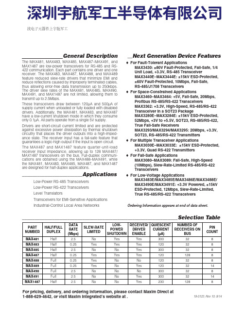
General DescriptionThe MAX481, MAX483, MAX485, MAX487–MAX491, andMAX1487 are low-power transceivers for RS-485 and RS-422 communication. Each part contains one driver and onereceiver. The MAX483, MAX487, MAX488, and MAX489feature reduced slew-rate drivers that minimize E MI andreduce reflections caused by improperly terminated cables,thus allowing error-free data transmission up to 250kbps.The driver slew rates of the MAX481, MAX485, MAX490,MAX491, and MAX1487 are not limited, allowing them totransmit up to 2.5Mbps.These transceivers draw between 120µA and 500µA ofsupply current when unloaded or fully loaded with disableddrivers. Additionally, the MAX481, MAX483, and MAX487have a low-current shutdown mode in which they consumeonly 0.1µA. All parts operate from a single 5V supply.Drivers are short-circuit current limited and are protectedagainst excessive power dissipation by thermal shutdowncircuitry that places the driver outputs into a high-imped-ance state. The receiver input has a fail-safe feature thatguarantees a logic-high output if the input is open circuit.The MAX487 and MAX1487 feature quarter-unit-loadreceiver input impedance, allowing up to 128 MAX487/MAX1487 transceivers on the bus. Full-duplex communi-cations are obtained using the MAX488–MAX491, whilethe MAX481, MAX483, MAX485, MAX487, and MAX1487are designed for half-duplex applications.________________________Applications Low-Power RS-485 Transceivers Low-Power RS-422 Transceivers Level Translators Transceivers for EMI-Sensitive Applications Industrial-Control Local Area Networks__Next Generation Device Features o For Fault-Tolerant Applications MAX3430: ±80V Fault-Protected, Fail-Safe, 1/4Unit Load, +3.3V, RS-485 Transceiver MAX3440E–MAX3444E: ±15kV ESD-Protected,±60V Fault-Protected, 10Mbps, Fail-Safe, RS-485/J1708 Transceivers o For Space-Constrained Applications MAX3460–MAX3464: +5V, Fail-Safe, 20Mbps,Profibus RS-485/RS-422 Transceivers MAX3362: +3.3V, High-Speed, RS-485/RS-422Transceiver in a SOT23 Package MAX3280E–MAX3284E: ±15kV ESD-Protected,52Mbps, +3V to +5.5V, SOT23, RS-485/RS-422,True Fail-Safe Receivers MAX3293/MAX3294/MAX3295: 20Mbps, +3.3V,SOT23, RS-485/RS-422 Transmitters o For Multiple Transceiver Applications MAX3030E–MAX3033E: ±15kV ESD-Protected,+3.3V, Quad RS-422 Transmitters o For Fail-Safe Applications MAX3080–MAX3089: Fail-Safe, High-Speed (10Mbps), Slew-Rate-Limited RS-485/RS-422Transceiverso For Low-Voltage ApplicationsMAX3483E/MAX3485E/MAX3486E/MAX3488E/MAX3490E/MAX3491E: +3.3V Powered, ±15kVESD-Protected, 12Mbps, Slew-Rate-Limited,True RS-485/RS-422 Transceivers For pricing, delivery, and ordering information, please contact Maxim Direct at1-888-629-4642, or visit Maxim Integrated’s website at .______________________________________________________________Selection Table19-0122; Rev 10; 9/14PARTNUMBERHALF/FULL DUPLEX DATA RATE (Mbps) SLEW-RATE LIMITED LOW-POWER SHUTDOWN RECEIVER/DRIVER ENABLE QUIESCENT CURRENT (μA) NUMBER OF RECEIVERS ON BUS PIN COUNT MAX481Half 2.5No Yes Yes 300328MAX483Half 0.25Yes Yes Yes 120328MAX485Half 2.5No No Yes 300328MAX487Half 0.25Yes Yes Yes 1201288MAX488Full 0.25Yes No No 120328MAX489Full 0.25Yes No Yes 1203214MAX490Full 2.5No No No 300328MAX491Full 2.5No No Yes 3003214MAX1487 Half 2.5No No Yes 2301288Ordering Information appears at end of data sheet.找电子元器件上宇航军工MAX481/MAX483/MAX485/MAX487–MAX491/MAX1487Low-Power, Slew-Rate-LimitedRS-485/RS-422 TransceiversPackage Information For the latest package outline information and land patterns, go to . Note that a “+”, “#”, or “-”in the package code indicates RoHS status only. Package drawings may show a different suffix character, but the drawing pertains to the package regardless of RoHS status.16Low-Power, Slew-Rate-Limited RS-485/RS-422 TransceiversMAX481/MAX483/MAX485/MAX487–MAX491/MAX1487Maxim Integrated cannot assume responsibility for use of any circuitry other than circuitry entirely embodied in a Maxim Integrated product. No circuit patent licenses are implied. Maxim Integrated reserves the right to change the circuitry and specifications without notice at any time. The parametric values (min and max limits) shown in the Electrical Characteristics table are guaranteed. Other parametric values quoted in this data sheet are provided for guidance.Maxim Integrated 160 Rio Robles, San Jose, CA 95134 USA 1-408-601-100017©2014 Maxim Integrated Products, Inc.Maxim Integrated and the Maxim Integrated logo are trademarks of Maxim Integrated Products, Inc.。

数视宝4路调制器(4路AV转RF信号调制器)数视宝4路调制器,又叫有线电视射频调制器,采用四路调制一体设计,将四台调制器整合为一台,充分节省机房机柜空间,方便安装调试。
产品按专业级固定频道邻频调制器设计,中频采用声表滤波器处理,有效地保证了残留边带特性,使之适用于邻频传输系统。
采用无源、高选择性单频道滤波器,有效地保证了调制器良好的寄生输出抑制性能。
其功能是把信号源(可以是数字电视机顶盒、卫星数字电视接收机、DVD机、电脑、摄像机、电视解调器等AV信号源)所提供的视频信号(VIDEO)和音频信号(AUDIO)调制成稳定的高频射频振荡信号,视频为调幅调制方式,音频为调频调制方式。
“数视宝”品牌4路射频调制器是酒店宾馆有线电视前端改造系统中使用最多的设备,目前酒店的电视系统,都是采用播出多少频道,就需要多少个机顶盒,这样不会影响信号、运行稳定。
调制器大体分两种,其邻频调制器与隔频调制器,市场上调制器的价格、规格也是五花八门,选择一款高质量的调制器,直接关系到整个有线电视前端改造系统。
选购调制器时,尽量选购邻频设计的调制器,但邻频调制器比隔频调制器价格要贵;也不是说隔频的调制器不好用,最主要还是看你安装的频道数量来决定你选购的种类;如(数视宝SUSPO-S188调制器)最多可以扩展到96个频道,以后增加频道比较方便。
隔频调制是通过高频处理方式,隔频调制器建议做20或40个频道。
如果经济允许,可以采购邻频调制器;要知道,购买调制器进行有线电视改造后,目前来说不会再进行系统升级,最少都要用10到20年,随着酒店规模的扩大就比较麻烦!数视宝4路调制器SUSPO-S8400应用:1、广泛应用于学校、宾馆、酒店、娱乐城、出租楼、工厂宿舍等拥有上百台电视的业主。
2、节省大量机顶盒投入,省去长年累月上缴机顶盒月租费,一次投资,长期受益。
3、不用重新布线和改变原来的线路,完全以往的收视习惯,无需增加,便于管理。
4、可融接用录像机、DVD、自办电影播放器等节目源,方便的播放节目。
USB-4751/4751L 48/24-Channel Digital Input/Output USB ModuleUser ManualCopyrightThe documentation and the software included with this product are copy-righted 2006 by Advantech Co., Ltd. All rights are reserved. Advantech Co., Ltd. reserves the right to make improvements in the productsdescribed in this manual at any time without notice. No part of this man-ual may be reproduced, copied, translated or transmitted in any form or by any means without the prior written permission of Advantech Co., Ltd.Information provided in this manual is intended to be accurate and reli-able. However, Advantech Co., Ltd. assumes no responsibility for its use, nor for any infringements of the rights of third parties, which may result from its use.AcknowledgementsIntel and Pentium are trademarks of Intel Corporation.Microsoft Windows and MS-DOS are registered trademarks ofMicrosoft Corp.All other product names or trademarks are properties of their respective owners.Part No. 20034751001st EditionPrinted in Taiwan September 2006USB-4751/4751L User Manual iiProduct Warranty (2 years)Advantech warrants to you, the original purchaser, that each of its prod-ucts will be free from defects in materials and workmanship for two years from the date of purchase.This warranty does not apply to any products which have been repaired or altered by persons other than repair personnel authorized by Advantech, or which have been subject to misuse, abuse, accident or improper instal-lation. Advantech assumes no liability under the terms of this warranty as a consequence of such events.Because of Advantech’s high quality-control standards and rigorous test-ing, most of our customers never need to use our repair service. If an Advantech product is defective, it will be repaired or replaced at no charge during the warranty period. For out-of-warranty repairs, you will be billed according to the cost of replacement materials, service time and freight. Please consult your dealer for more details.If you think you have a defective product, follow these steps:1.Collect all the information about the problem encountered. (Forexample, CPU speed, Advantech products used, other hardwareand software used, etc.) Note anything abnormal and list anyonscreen messages you get when the problem occurs.2.Call your dealer and describe the problem. Please have your man-ual, product, and any helpful information readily available.3.If your product is diagnosed as defective, obtain an RMA (returnmerchandize authorization) number from your dealer. This allows us to process your return more quickly.4.Carefully pack the defective product, a fully-completed Repair andReplacement Order Card and a photocopy proof of purchase date(such as your sales receipt) in a shippable container. A productreturned without proof of the purchase date is not eligible for war-ranty service.5.Write the RMA number visibly on the outside of the package andship it prepaid to your dealer.iiiCEThis product has passed the CE test for environmental specificationswhen shielded cables are used for external wiring. We recommend the use of shielded cables. This kind of cable is available from Advantech. Please contact your local supplier for ordering information.Technical Support and AssistanceStep 1. Visit the Advantech web site at /support where you can find the latest information about the product.Step 2. Contact your distributor, sales representative, or Advantech's cus-tomer service center for technical support if you need additionalassistance. Please have the following information ready beforeyou call:- Product name and serial number- Description of your peripheral attachments- Description of your software (operating system, version, appli-cation software, etc.)- A complete description of the problem- The exact wording of any error messagesDocument FeedbackTo assist us in making improvements to this manual, we would welcome comments and constructive criticism. Please send all such - in writing to: *********************Safety Precaution - Static ElectricityFollow these simple precautions to protect yourself from harm and the products from damage.1.To avoid electrical shock, always disconnect the power from yourPC chassis before you work on it. Don't touch any components onthe CPU card or other cards while the PC is on.2.Disconnect power before making any configuration changes. Thesudden rush of power as you connect a jumper or install a card maydamage sensitive electronic components.USB-4751/4751L User Manual ivContentsChapter1Introduction (2)1.1Hardware Features (2)1.2Software Overview (3)1.2.1More on the CD (3)Chapter2Installation (6)2.1Unpacking (6)2.2Driver Installation (7)2.3Hardware Installation (9)2.4Hardware Uninstallation (9)Figure 2.1:Unplug or Eject Hardware Dialog (10)Figure 2.2:Stop a Hardware device dialog box (10)Chapter3Signal Connections (12)3.1Overview (12)3.2I/O Connectors (12)3.2.1Pin Assignments (12)Figure 3.1:I/O Connector Pin Assignment (12)Figure 3.2:Opto-22 CN1/CN2 (13)3.2.2I/O Connector Signal Description (14)Table 3.1:I/O Connector Signal Description (14)3.2.3LED Indicator Status Description (14)Table 3.2:LED Indicator Status Description (14)3.3Digital I/O Connections (15)3.3.1Dry Contact Support for Digital Input (15)Figure 3.3:Digital Input Connections (15)3.4Field Wiring Considerations (16)Appendix A Specifications (18)A.1Digital Input/Output (18)A.2Counter (18)A.3General (18)v Table of ContentsUSB-4751/4751L User Manual viC H A P T E R1Introduction Sections include:• Hardware Features • Software OverviewChapter 1 IntroductionThank you for buying the Advantech’s USB-4751/4751L data acquisition module. The Advantech USB-4751/4751L is a powerful data acquisition (DAS) module for the USB port. It features a unique circuit design and complete functions for data acquisition and control.1.1 Hardware FeaturesUSB-4751/4751L features excellent measurement & control functions:• 48/24 TTL digital I/O lines• 50-pin Opto-22 compatible box header• Emulates mode 0 of 8255 PPI• Buffered circuits for higher driving capacity than 8255• Interrupt handling• Timer/ Counter interrupt capability• Supports both dry and wet contact• 50-pin Opto-22 compatible box header• Compatible with USB 1.1/2.0• Bus-poweredNote:You can install up to sixteen USB-4751/4751L’sto a system because of the restriction of deviceBoardIDNote:The power output of an USB port is 500 mA,while the USB-4751/4751L requires 500mA(Max.). This means that if an USB hub is used, itwill need an external power supply to supportmore than one USB-4751/4751L device.Note:For detailed specifications of USB-4751/4751L,please refer to Appendix A, Specifications.USB-4751/4751L User Manual21.2 Software OverviewAdvantech offers a rich set of DLL drivers, third-party driver support and application software on the companion CD-ROM to help fully exploit the functions of your device. Advantech’s Device Drivers feature a complete I/O function library to help boost your application performance and work seamlessly with development tools such as Visual C++, Visual Basic,Inprise C++ Builder, and Inprise Delphi.1.2.1 More on the CDFor instructions on how to begin programming in each development tool, Advantech offers some tutorial chapters in the Device Drivers Manual for your reference. Please refer to the corresponding sections in these chap-ters on the Device Drivers Manual to begin your programming efforts.You can also look at the example source code provided for each program-ming tool, since they can get you very well oriented.The Device Drivers Manual can be found on the companion CD-ROM.Alternatively, if you have already installed the Device Drivers on your system, The Device Drivers Manual can be readily accessed through the Start button:Start/Programs/Advantech Automation/Advantech Device Manager / Device Driver’s ManualThe example source code can be found under the corresponding installa-tion folder such as the default installation path:\Program Files\Advantech\ADSAPI\Examples3Chapter 1USB-4751/4751L User Manual4C H A P T E R2InstallationSections include:• Unpacking • Driver Installation • Hardware Installation • Hardware UninstallationChapter 2 Installation2.1 UnpackingAfter receiving your USB-4751/4751L package, please inspect its con-tents first. The package should contain the following items:• USB-4751/4751L Module• Shielded USB 2.0 Cable (1.8 m)• Companion CD-ROM (DLL driver included)• User ManualThe USB-4751/4751L Module harbors certain electronic componentsvulnerable to electrostatic discharge (ESD). ESD could easily damage the integrated circuits and certain components if preventive measures are not carefully paid attention to. Before removing the module from theantistatic plastic bag, you should take following precautions to ward off possible ESD damage:• Touch the metal part of your computer chassis with your hand to dis-charge static electricity accumulated on your body. One can also use a grounding strap.• Make contact between the antistatic bag and ground before opening.After taking out the module, you should first:Inspect the module for any possible signs of external damage (loose or damaged components, etc.). If the module is visibly damaged, pleasenotify our service department or our local sales representative immedi-ately. Avoid using a damaged module with your system.• Avoid physical contact with materials that could hold static electricitysuch as plastic, vinyl and Styrofoam.USB-4751/4751L User Manual62.2 Driver InstallationWe recommend you install the software driver before you install theUSB-4751/4751L module into your system, since this will guarantee a smooth installation process.The 32-bit DLL driver Setup program for the USB-4751/4751L module is included on the companion CD-ROM that is shipped with your module package. Please follow the steps on the following page to install thedriver software:7Chapter 2USB-4751/4751L User Manual8For further information on driver-related issues, an online version of the Device Drivers Manual is available by accessing the following path:Start\Programs\Advantech Automation\Device Manager\Device Driver’s Manual2.3 Hardware InstallationNote:Make sure you have installed the software driverbefore you install the module (please refer toSection 2.2 Driver Installation)After the DLL driver installation is completed, you can now go on toinstall the USB-4751/4751L module in any USB port that supports the USB 1.1/2.0 standard, on your computer. Please follow the steps below to install the module on your system.Step 1: Touch the metal part on the surface of your computer to neutral-ize the static electricity that might be in your body.Step 2: Plug your USB module into the selected USB port. Use of exces-sive force must be avoided; otherwise the module might get damaged.Note:In case you installed the module without installingthe DLL driver, Win2000/XP will recognize yourmodule as an “unknown device”. After reboot,it willprompt you to provide necessary driver. You shouldignore the prompting messages and set up thedriver according to the steps described in Sec.2.2.After your module is installed, you can configure it using the Advantech Device Manager. The Device Driver's Manual can be found at:Start\Programs\Advantech Automation\Advantech Device Man-ager\Device Driver’s Manual2.4 Hardware UninstallationThough the Advantech USB modules are hot swappable, we still recom-mend you to follow the hardware un-installation procedure to avoid any unpredictable damages to your device or your system.Step1: Close the applications of the USB module.Step2: Right click the “Unplug or Eject Hardware” icon on your task bar.9Chapter 2USB-4751/4751L User Manual10Figure 2.1: Unplug or Eject Hardware DialogStep3: Select “Advantech USB-4751/L Device” and press “Stop” Button.Figure 2.2: Stop a Hardware device dialog boxStep4: Unplug your USB device from the USB port.Note:Please make sure that you have closed the application before unplugging the USB device, otherwise unex-pected system error or damage may occur.C H A P T E R3Signal ConnectionsSections include:• Overview• Digital I/O Connections • Field Wiring ConsiderationsUSB-4751/4751L User Manual12Chapter 3 Signal Connections3.1 OverviewMaintaining good signal connections is one of the most important factors in ensuring that your application system is sending and receiving data correctly. A good signal connection can avoid unnecessary and costly damage to your PC and other hardware devices.3.2 I/O ConnectorsUSB-4751/4751L is equipped with one plug-in screw-terminal connector and two (one for USB-4751L) standard Opto-22 connectors that can be used with a variety of Advantech's wiring boards.3.2.1 Pin AssignmentsFigure 3.1: I/O Connector Pin AssignmentFigure 3.2: Opto-22 CN1/CN2Opto-22 CN1 Opto-22 CN2 (USB-4751 Only)1PC072GND 1PC172GND 3PC064GND3PC164GND5PC056GND5PC156GND7PC048GND7PC148GND9PC0310GND9PC1310GND11PC0212GND11PC1212GND13PC0114GND13PC1114GND15PC0016GND15PC1016GND17PB0718GND17PB1718GND19PB0620GND19PB1620GND21PB0522GND21PB1522GND23PB0424GND23PB1424GND25PB0326GND25PB1326GND27PB0228GND27PB1228GND29PB0130GND29PB1130GND31PB0032GND31PB1032GND33PA0734GND33PA1734GND35PA0636GND35PA1636GND37PA0538GND37PA1538GND39PA0440GND39PA1440GND41PA0342GND41PA1342GND43PA0244GND43PA1244GND45PA0146GND45PA1146GND47PA0048GND47PA1048GND49+5V_OUT50GND49+5V_OUT50GND13Chapter 3USB-4751/4751L User Manual143.2.2 I/O Connector Signal Description3.2.3 LED Indicator Status DescriptionThe USB Module is equipped with a LED indicator to show the current status of the device. When you plug the USB device into the USB port, the LED indicator will blink five times and then stay lit to indicate that it is on. Please refer to the following table for detailed LED indicator status information.Signal Ref.Direction DescriptionPA<0~7, 10~17>GND Input/Out-put Digital input/ output port A, channel 0~7 & channel 10~17.PB<0~7, 10~17>GND Input/Out-put Digital input/ output port B, channel 0~7 & channel 10~17.PC<0~7, 10~17>GND Input/Out-put Digital input/ output port C, channel 0~7 & channel 10~17.+5V_OUT GND Output +5V DC powerC<1,2>_Out GND Output Output pins of counter/ timer 1 and 2C<1,2>_Gate GND Input Gate control pins of counter/ timer 1 and 2C<1,2>_In GND Input External clock source of counter/ timer 1 and 2INT_OutGNDOutputInterrupt output. This pin changes to logic 1 whenever theUSB-4751 generates an interrupt, and returns to logic 0 when the interrupt is cleared.GND --Digital groundLED Status DescriptionOn Device ready for work OffDevice not ready to work Slow Blinking (5 times)Device initialization Fast Blinking(Depends on data transfer speed).Device working15Chapter 3 3.3 Digital I/O Connections3.3.1 Dry Contact Support for Digital InputEach digital input channel accepts either dry contact or 0 ~ 5 VDC wet contact inputs. Dry contact capability allows the channel to respond to changes in external circuitry (e.g., the closing of a switch in the external circuitry) when no voltage is present in the external circuit. Figure 3-3 shows external circuitry with both wet and dry contact components, con-nected as an input source to one of the card's digital input channels.Figure 3.3: Digital Input Connections3.4 Field Wiring Considerations• When you use USB-4751/4751L to acquire data from outside, noises in the environment might significantly affect the accuracy of your mea-surements if due cautions are not taken. The following measures willbe helpful to reduce possible interference running signal wires between signal sources and the USB-4751/4751L.• The signal cables must be kept away from strong electromagneticsources such as power lines, large electric motors, circuit breakers orwelding machines, since they may cause strong electromagnetic inter-ference. Keep the analog signal cables away from any video monitor,since it can significantly affect a data acquisition system.• If the cable travels through an area with significant electromagneticinterference, you should adopt individually shielded, twisted-pair wires as the analog input cable. This type of cable has its signal wires twisted together and shielded with a metal mesh. The metal mesh should only be connected to one point at the signal source ground.• Avoid running the signal cables through any conduit that might havepower lines in it.• If you have to place your signal cable parallel to a power line that has a high voltage or high current running through it, try to keep a safe dis-tance between them. Or place the signal cable in a right angle to thepower line to minimize the undesirable effect.USB-4751/4751L User Manual16A P P E N D I X A SpecificationsUSB-4751/4751L User Manual 18Appendix A Specifications A.1 Digital Input/Output A.2 CounterA.3 General Channels48 Bi-directional (24 for USB-4751L)ProgrammingMode8255 PPI Mode0Input VoltageLow 0.8 V max High 2.0 V min Output VoltageLow 0.5 V max. @ 12mA (sink)High 3.8 V min. @ -12mA (source)(each line)3.8 V min.@5mA(source)(high of every line)+5V Output100mA max.Interrupt Mode PC0 source; PC4 gate/PC0 sourceChannels2 independent Resolution32-bit counters (low 16bit by hardware and high 16bit by ARM)CompatibilityTTL compatible logical level input Base ClockExternal 8MHz max. 2 independent program-mable clock sourcesInternal 20MHz max.FrequencymeasurementInput frequency from 0.1Hz to 10Mhz PWM Generation2Hz to 10Mhz External Input Divide 2 to 65535I/O Connector TypeOpto-22 * 2 and 10-pin screw terminal *1Dimensions132 X 80 X 32 mm (5.2” X 3.2” X 1.3”)PowerConsumption5 V @ 500 mA max.TemperatureOperation 0~60° C (32~140° F) (refer to IEC 68-2-1, 2)Storage -20~70° C (-4~158° F)Relative Humidity 5%~95% RH non-condensing (refer to IEC 68-2-1, 2)。
典型应用电路CHANNEL 2BUCK REGULATOR (1.2A/2.5A/4A)CHANNEL 3BUCK REGULATOR(1.2A)OSCILLATORINT VREG 100mAQ1Q2L1L2VREGSYNC/MODERT FB1BST1SW1DL1PGND DL2SW2BST2FB2L3BST3SW3FB3PGND3L4VREGBST4SW4FB4PGND4VREGPVIN1COMP1EN1PVIN2COMP2EN2PVIN3SS34COMP3EN3PVIN4COMP4EN4C2C1C4C3C5C6C7C8C9C10C11C12C134.5V TO 15VVOUT1VOUT2VOUT3VOUT4VOUTxR ILIM1R ILIM2VREGEXPOSED PADSS12C0VDDWATCHDOG AND RESETVTHWDIMRRSTOADP5053CHANNEL 1BUCK REGULATOR (1.2A/2.5A/4A)CHANNEL 4BUCK REGULATOR(1.2A)PWRGD 11636-001图1.表1. 该系列产品型号型号 通道I 2C 封装ADP5050 4个降压器、1个LDO 是48引脚 LFCSP ADP5051 4个降压器、电源监控器是 48引脚 LFCSP ADP5052 4个降压器、1个LDO 无 48引脚 LFCSP ADP50534个降压器、电源监控器无48引脚 LFCSPADP5053集成四通道降压调节器和监控电路的电源解决方案产品特性宽输入电压范围:4.5 V 至15.0 V 输出精度:±1.5%(整个温度范围内) 可调开关频率范围:250 kHz 至1.4 MHz 可调/固定输出选项,可通过工厂熔丝选择 电源调节通道1和通道2:带低端FET 驱动器的可编程1.2 A/2.5 A/4 A 同步降压调节器通道3和通道4:1.2 A 同步降压调节器 8 A 单通道输出(通道1和通道2并联工作) 精密使能,0.8 V 精确阈值 有源输出放电开关FPWM 或自动PWM/PSM 选择 频率同步输入或输出针对OVP/OCP 故障提供可选的闩锁保护 所选通道的电源良好指示 UVLO 、OCP 和TSD 保护开漏处理器复位,带外部可调阈值监控 看门狗刷新输入 手动复位输入应用小型蜂窝基站FPGA 和处理器应用 安防和监控 医疗应用概述ADP5053集成了四个高性能降压调节器、一个监控电路、一个看门狗定时器和手动复位功能,48引脚的LFCSP 封装中可满足严苛的性能和电路板空间要求。
AD4D双通道接收机AD4D Axient Digital Dual Channel Receiver User Guide Version: 4 (2019-E)Table of ContentsAD4D双通道接收机4重要安全事项! 4澳大利亚无线警告4 AD4D Axient 数字双通道无线接收机5特点 5附带组件6安装说明6硬件7接收机前面板 7接收机背板 8菜单和配置10访问设备配置菜单或频道菜单 10主屏幕 10屏幕图标11设备配置菜单和参数 12 AD4D 设备配置参数 13频道菜单参数 16无线电射频 (RF) 设置18设置射频调谐频带 18红外同步 19手动设置频率 19频道扫描和组扫描 20从频谱管理器请求新频率 21传输模式 21将发射机与发射机插槽对准 21干扰管理 22频道质量计 23频率分集 23天线偏移 24无线射频级联端口 24固件 24音频设置25调节频道增益和音频输出 25音频发生器 25耳机监听 26系统增益 26联网27接收机连网 27网络浏览器 28网络故障排除 28操作29分配设备 ID 29分配频道名称 29控制器的锁定和解锁 29显示屏选项 29将接收机设置保存为用户预设 30使用红外预设对发射机编程 30加密 30将接收机恢复为出厂设置 31冷却风扇 31故障排除31功率 31增益 31线缆 32界面锁定 32加密不匹配 32固件不匹配 32无线电射频 (RF) 32规格33表格和图 38接收机频段38认证391.2.3.4.5.6.7.8.9.10.11.12.13.14.15.16.17.18.19.20.21.AD4D双通道接收机重要安全事项!必须阅读这些注意事项。
必须保留这些注意事项。
必须注意所有警告内容。
必须遵循所有注意事项。
不要在靠近水的地方使用本设备。
只能用干布擦拭设备。
不要堵塞任何通风口。
留出足够的距离,确保充分通风,并安装在符合制造商要求的位置。