(完整版)常熟理工学院本科_毕业设计(论文)外文翻译_
- 格式:doc
- 大小:40.00 KB
- 文档页数:3

大连东软信息学院
毕业设计(论文)外文资料及译文
系所:
专业:
班级:
姓名:
学号:
大连东软信息学院
Dalian Neusoft University of Information
外文资料和译文格式要求
一、装订要求
1、外文资料原文(复印或打印)在前、译文在后、最后为指导教师评定成绩。
2、译文必须采用计算机输入、打印。
3、A4幅面打印,于左侧装订。
二、撰写要求
1、外文文献内容与所选课题相关。
2、本科学生译文汉字字数不少于4000字,高职学生译文汉字字数不少于2000字。
三、格式要求
1、译文字号:中文小四号宋体,英文小四号“Times New Roman”字型,全文统一,首行缩进2个中文字符,1.5倍行距。
2、译文页码:页码用阿拉伯数字连续编页,字体采用“Times New Roman”字体,字号小五,页底居中。
3、译文页眉:眉体使用单线,页眉说明五号宋体,居中“大连东软信息学院本科毕业设计(论文)译文”。

本科生毕业设计(论文)外文翻译外文原文题目:Real-time interactive optical micromanipulation of a mixture of high- and low-index particles中文翻译题目:高低折射率微粒混合物的实时交互式光学微操作毕业设计(论文)题目:阵列光镊软件控制系统设计姓名:任有健学院:生命学院班级:06210501指导教师:李勤高低折射率微粒混合物的实时交互式光学微操作Peter John Rodrigo Vincent Ricardo Daria Jesper Glückstad丹麦罗斯基勒DK-4000号,Risø国家实验室光学和等离子研究系jesper.gluckstad@risoe.dkhttp://www.risoe.dk/ofd/competence/ppo.htm摘要:本文论证一种对于胶体的实时交互式光学微操作的方法,胶体中包含两种折射率的微粒,与悬浮介质(0n )相比,分别低于(0L n n <)、高于(0H n n >)悬浮介质的折射率。
球形的高低折射率微粒在横平板上被一批捕获激光束生成的约束光势能捕获,捕获激光束的横剖面可以分为“礼帽形”和“圆环形”两种光强剖面。
这种应用方法在光学捕获的空间分布和个体几何学方面提供了广泛的可重构性。
我们以实验为基础证实了同时捕获又独立操作悬浮于水(0 1.33n =)中不同尺寸的球形碳酸钠微壳( 1.2L n ≈)和聚苯乙烯微珠( 1.57H n =)的独特性质。
©2004 美国光学学会光学分类与标引体系编码:(140.7010)捕获、(170.4520)光学限制与操作和(230.6120)空间光调制器。
1 引言光带有动量和角动量。
伴随于光与物质相互作用的动量转移为我们提供了在介观量级捕获和操作微粒的方法。
过去数十年中的巨大发展已经导致了在生物和物理领域常规光学捕获的各种应用以及下一代光学微操作体系的出现[1-5]。

本科毕业设计外文翻译题目:德黑兰城市发展学院: 城市建设学院专业: 建筑学学号:学生姓名:指导教师:日期: 二零一一年六月First Chapter:Development of the city of TehranAli MadanipourTehran :the making of a metropolis,First Chapter:Development New York John Wiley,1998,page five to page eleven。
第一章:德黑兰市的发展阿里.马丹妮普尔德黑兰:一个大都市的建造,第一章:德黑兰市的发展,阿1998,第五页到第十一页。
德黑兰市的发展全市已长成了一定的规模性和复杂性,以这样的程度,空间管理需要另外的手段来处理城市组织和不断发展的复杂性,并为城市总体规划做准备。
第二次世界大战后,在盟军占领国家的期间,有一个时期的民主化,在冷战时开始的政治紧张局势之后,它们互相斗争对石油的控制权。
这个时期已经结束于1953年,结果是由政变产生了伊朗王,那个后来担任了25年的行政君主的人。
随着高出生率和农村向城市迁移,德黑兰和其他大城市增长加剧甚至比以前更快地。
到1956年,德黑兰的人口上升到150万,到了1966至300万, 1976至450万,其规模也从1934年46平方公里到1976年的250平方公里。
从石油行业的收入增长创造的盈余资源,需要流通和经济的吸收。
50年代中期,特别是在工业化的驱动下德黑兰许多大城市有了新工作。
20世纪60年代的土地改革释放了大量来自农业的农村人口,这是不能吸收的指数人口增长。
这种新的劳动力被吸引到城市:到新的产业,到似乎始终蓬勃发展建筑界,去服务不断增长公共部门和官僚机构。
德黑兰的角色是国家的行政,经济,文化中心,它坚定而巩固地通往外面的世界。
德黑兰战后的城市扩张,是在管制、私营部门的推动,投机性的发展下进行的。
房屋一直供不应求,并有大量可用的富余劳动力和资本,因此在德黑兰建筑行业蓬勃发展,土地和财产的价格不断上涨。

毕业设计(论文)外文资料翻译附件1 :外文资料翻译译文双闭环直流调速系统的说明一、系统分析与综合1. 系统分析(1)在转速、电流双闭环调速系统中,若要改变电动机的转速,应调节什么参数?改变转速调节器的放大倍数Kn行不行?改变电力电子变换器的放大系数Ks 行不行?改变转速反馈系数行不行?若要改变电动机的堵转电流,应调节系统中的什么参数?答:若要改变电动机的转速,改变转速调节器的放大倍数Kn 和电力电子变换器的放大系数Ks 都不行,稳定时n=Un=Un*,所以只有改变给定值Un*和反馈系数才行。
若要改变电动机的堵转电流,同样只须改变给定值Uim*和反馈系数,因为,稳定时,Uim* = Idm, 从式中可得出。
(2)转速、电流双闭环调速系统稳态运行时,两个调节器的输入偏差电压和输出电压各是多少?答:转速、电流双闭环调速系统稳态运行时,两个调节器的输入偏差电压均是零,由式子n=Un=Un*,n=n0 ; Uim* = Idm, Idm=Idl 。
(3)在转速、电流双闭环调速系统中,两个调节器均采用PI 调节器。
当系统带额定负载运行时,转速反馈线突然断线,系统重新进入稳态后,电流调节器的输入偏差电压Ui 是否为零?为什么?答:当系统带额定负载运行时,转速反馈线突然断线,则Un=0,Un =Un*-Un=Un*, 使Ui 迅速达到Uim ,Ui 0 ,速度n 上升,当系统重新进入稳态后,即Id=Idl ,那么,Ui = Uim*- Idl 0,Ui 也不再变化,转速n也不再变化,但,此时的转速n 比反馈线断线时的转速要大。
(4)为什么用积分控制的调速系统是无静差的?答:在积分调节器的调速系统中,能实现无静差,是由于积分调节器控制特点,即积分的记忆和积累作用。
(5)双环调速系统(PI),负载变化,Idl>Idm, 问双环调速系统ACR和ASR 怎么调节,结果如何?答:当负载变化时,Idl>Idm, 转速迅速下降,电流Id 很快增加到Idm,而达限幅值,速度ASR迅速饱和,ACR一直在限流状态下,形成堵转现象,长时间运行会损坏系统。
常熟理工学院毕业设计(论文)有关文件及管理规定1、常熟理工学院毕业设计(论文)工作条例(修订稿)2、常熟理工学院本科生毕业设计(论文)评分标准3、常熟理工学院毕业设计(论文)管理规定4、常熟理工学院校外做毕业设计(论文)的管理规定(试行)5、常熟理工学院校外做毕业设计(论文)申请表6、常熟理工学院校外做毕业设计(论文)情况汇总表7、常熟理工学院本科生团队毕业设计(论文)工作规范(试行)8、常熟理工学院毕业设计(论文)答辩工作规程9、常熟理工学院本科毕业设计(论文)撰写规范常熟理工学院毕业设计(论文)工作条例(修订稿)为了进一步规范我校的毕业设计(论文)工作,切实保证我校本科生毕业设计(论文)的教学质量,我们在以往有关文件规定的基础上,修订了《常熟理工学院毕业设计(论文)工作规程》。
各二级学院应以此文件为指导,做好毕业设计(论文)工作。
第一章总则第一条毕业设计(论文)是学生在校期间最重要的综合性实践教学环节,是学生在校所学知识的综合应用,是检验学校培养质量的重要依据,也是学生毕业及学位资格认定的重要依据之一。
为进一步规范毕业设计(论文)工作,保证毕业设计(论文)及人才培养质量,特制定本规程。
第二条毕业设计(论文)工作的目的是培养学生综合运用所学基础理论、专业知识和基本技能来分析、解决实际问题的能力。
因此,毕业设计(论文)工作应注重学生独立工作和研究能力的锻炼,重视学生创新精神和创造能力的培养。
第三条本规程适用于常熟理工学院各本科专业。
第二章组织与管理工作第四条毕业设计(论文)工作实行在学校主管教学校长的统一领导下,由“教务处—学院—系三级管理。
学校教务处统一协调与管理,各学院和系具体组织落实。
各学院主管教学的院长应对本院毕业设计(论文)工作的组织管理和教学质量全面负责。
具体任务为:教务处负责毕业设计(论文)工作的宏观管理和指导,协调教学资源的配置,评价毕业设计(论文)工作,组织毕业设计(论文)教学研究和优秀毕业设计(论文)评选;学院主管教学院长是毕业设计(论文)工作的直接领导者和责任人,全面负责本学院各专业的毕业设计(论文)工作;系(教研室)在学院的领导下具体负责毕业设计(论文)的组织及实施工作。

Computer networking summarizeNetworking can be defined as the linking of people, resources and ideas. Networking occurs via casual encounters, meetings, telephone conversation, and the printed words. Now the computer networking provide beings with new networking capabilities. Computer network are important for services because service tasks are information intensive. During the is transmitted between clients, coworkers, management, funding sources, and policy makers. Tools with rapidly speed up communication will dramatically affect services.Computer network growing explosively. Two decades ago, few people essential part of our infrastructure. Networking is used in every aspect of business, including advertising, production, shipping, planning, bulling, and accounting. Consequently, most corporations in on-line libraries around the world. Federal, state, and local government offices use networks, as do military organizations. In short, computer networks are everywhere.The growth in networking economic impact as well. An entire industry jobs for people with more networking expertise. Companies need workers to plan, acquire, install, operate, and manage the addition computer programming is no longer restricted to individual computers; programmers are expected to design and implement application software that can communicate with software on other computers.Computer networks link computers by communication lines and software protocols, allowing data to be exchanged rapidly and reliably. Traditionally, they split between wide area networks (WANs) and local area networks (LANs). A WAN is a network connected over long-distance telephone lines, and a LAN is a localized network usually in one building or a group of buildings close together. The distinction, computers. Today networks carry e-mail, provide access to public databases, and are beginning to be used for distributed systems. Networks also allow users in one locality to share expensive resources, such as printers and disk-systems.Distributed computer systems are built using networked computers that cooperate to perform tasks. In this environment, each part of the networked system does what it is best at. The of a personal computer or workstation provides a good user interface. The mainframe, on the other the results to the users. In a distributed environment, a user might use in a special language (e. g. Structured Query Language-SQL), to the mainframe, which then parrrses the query, returning the user only the data requested. The user might then use the data. By passing back the user’s PC only the specific information requested, network traffic is reduced. If the whole file were transmitted, the PC would then of one network to access the resources on a different type of network. For example, a gateway could be used to connect a local area network of personal computers to a mainframe computer network. For example, if a company this example, using a bridge makes more sense than joining all thepersonal computers together in one large network because the individual departments only occasionally need to access information on the other network.Computer networking technology can be divided into four major aspects.The first is the data transmission. It explains that at the lowest level electrical signals traveling across wires are used to carry information, and shows be encoded using electrical signals.The second focuses on packet transmission. It explains why computer network use packets, and shows . LANs and WANs discussed above are two basic network.The third covers internetworking—the important idea that allows system, and TCPIP, the protocol technology used in global internet.The fourth explains networking applications. It focuses on , and programs provide services such as electronic mail and Web browsing.Continued growth of the global Internet is one of most interesting and exciting phenomena in networking. A decade ago, the Internet was a research project that involved a few dozen sites. Today, the Internet into a production communication system that reaches millions of people in almost all countries on all continents around the world. In the United States, the Internet connects most corporations, colleges and universities, as well as federal, state, and local government offices. It will soon reach most elementary,junior, and senior addition, many private residences can reach the Internet through a dialup telephone connection. Evidence of the Internet’s impact on society can be seen in advertisements, in magazines and on television, which often contain a reference to an Internet Web site that provide additional information about the advertiser’s products and services.A large organization with diverse networking requirements needs multiple physical networks. More important, if the organization chooses the type network that is best for each task, the organization will network can only communicate with other computers attached to same network. The problem became evident in the 1970s as large organizations began to acquire multiple networks. Each network in the organizations formed an island. In many early installations, each computer attached to a single network and employees employees was given access to multiple svreens and keyboards, and the employee was forced to move form one computer to another to send a massage across the appropriate network. Users are neither satisfied nor productive when they must use a separate computer. Consequently, most modern computer communication syetem allow communication between any two computers analogous to the way a telephone system provides communication between any two telephones. Known as universal service, the concept is a fundamental part of networking. With universal service, a user on any computer in any part of an organization can send messages or data to any other users. Furthermore, a user does not need to change computer systems whenchanging tasks—all information is available to all computers. As a result, users are more productive.The basic component used to commect organization to choose network technologies appropriate for each need, and to use routers to connect all networks into a single internet.The goal of internetworking is universal service across an internet, routers must agree to forward information from a source on one network to a specified destination on another. The task is complex because frame formats and addressing schemes used by underlying networks can differ. As s resulrt, protocol software is needed on computers and routers make universal service possible. Internet protocols overcome differences in frame formats and physical addresses to make communication pissible among networks that use different technologies.In general, internet software provides the appeatrance of a single, seamless communication system to which many computers attach. The syetem offers universal service :each computer is assigned an address, and any computer can send a packet to any other computer. Furthermore, internet protocol software —neither users nor application programs are a ware of the underlying physical networks or the routers that connect them.We say that an internet is a virtual network system because the communication system is an abstraction. That is, although a combination of of a uniform network syetem, no such network exists.Research on internetworking modern networking. In fact,internet techmology . Most large organizations already use internetworking as primary computer communication mechanism. Smaller organizations and individuals are beginning to do so as well. More inportant, the TCPIP technology computers in schools, commercial organications, government, military sites and individuals in almost all countries around the world.电脑网络简述网络可被定义为人、资源和思想的联接。

南京理工大学紫金学院毕业设计(论文)外文资料翻译系:机械系专业:车辆工程专业姓名:宋磊春学号:070102234外文出处:EDU_E_CAT_VBA_FF_V5R9(用外文写)附件:1。
外文资料翻译译文;2.外文原文.附件1:外文资料翻译译文CATIA V5 的自动化CATIA V5的自动化和脚本:在NT 和Unix上:脚本允许你用宏指令以非常简单的方式计划CATIA。
CATIA 使用在MS –VBScript中(V5.x中在NT和UNIX3。
0 )的共用部分来使得在两个平台上运行相同的宏。
在NT 平台上:自动化允许CATIA像Word/Excel或者Visual Basic程序那样与其他外用分享目标。
ATIA 能使用Word/Excel对象就像Word/Excel能使用CATIA 对象。
在Unix 平台上:CATIA将来的版本将允许从Java分享它的对象。
这将提供在Unix 和NT 之间的一个完美兼容。
CATIA V5 自动化:介绍(仅限NT)自动化允许在几个进程之间的联系:CATIA V5 在NT 上:接口COM:Visual Basic 脚本(对宏来说),Visual Basic 为应用(适合前:Word/Excel ),Visual Basic。
COM(零部件目标模型)是“微软“标准于几个应用程序之间的共享对象。
Automation 是一种“微软“技术,它使用一种解释环境中的COM对象。
ActiveX 组成部分是“微软“标准于几个应用程序之间的共享对象,即使在解释环境里。
OLE(对象的链接与嵌入)意思是资料可以在一个其他应用OLE的资料里连结并且可以被编辑的方法(在适当的位置编辑).在VBScript,VBA和Visual Basic之间的差别:Visual Basic(VB)是全部的版本。
它能产生独立的计划,它也能建立ActiveX 和服务器。
它可以被编辑。
VB中提供了一个补充文件名为“在线丛书“(VB的5。

Library of C the CNC industrialdeveloped tens of thousands and educational field, he hasNUMERICAL CONTROLNumerical Control technology as it is known today, emerged in the mid 20th century. It can be traced to the year of 1952, the U.S. Air Force, and the names of John Parsons and the Massachusetts Institute of Technology in Cam-bridge, MA, USA. It was not applied in production manu-facturing until the early 1960's. The real boom came in the form of CNC, around the year of 1972, and a decade later with the introduction of affordable micro computers. The history and development of this fascinating technology has been well documented in many publications.In the manufacturing field, and particularly in the area of metal working, Numerical Control technology has caused something of a revolution. Even in the days before comput-ers became standard fixtures in every company and in many homes, the2machine tools equipped with Numerical Control system found their special place in the machine shops. The recent evolution of micro electronics and the never ceasing computer development, including its impact on Numerical Control, has brought significant changes to the manufacturing sector in general and metalworking in-dustry in particular.DEFINITION OF NUMERICAL CONTROLIn various publications and articles, many descriptions have been used during the years, to define what Numerical Control is. It would be pointless to try to find yet another definition, just for the purpose of this handbook. Many of these definitions share the same idea, same basic concept, just use different wording.The majority of all the known definitions can be summed up into a relatively simple statement:Numerical Control can be defined as an operation of machine tools by the means of specifically coded instructions to the machine control systemThe instructions are combinations of the letters of alpha-bet, digits and selected symbols, for example, a decimal point, the percent sign or the parenthesis symbols. All in-structions are written in a logical order and a predetermined form. The collectionNUMERICAL CONTROLof all instructions necessary to ma-chine a part is called an NC Program, CNC Program, or a Part Program. Such a program can be stored for a future use and used repeatedly to achieve identical machining re-sults at any time.♦ NC and CNC TechnologyIn strict adherence to the terminology, there is a differ-ence in the meaning of the abbreviations NC and CNC. The NC stands for the older and original Numerical Control technology, whereby the abbreviation CNC stands for the newer Computerized Numerical Control technology, a modem spin-off of its older relative. However, in practice, CNC is the preferred abbreviation. To clarify the proper us-age of each term, look at the major differences between the NC and the CNC systems.Both systems perform the same tasks, namely manipula-tion of data for the purpose of machining a part. In both cases, the internal design of the control system contains the logical instructions that process the data. At this point the similarity ends. The NC system (as opposed to the CNC system) uses a fixed logical functions, those that are built-in and perma-nently wired within the control unit. These functions can-not be changed by the programmer or the machine opera-tor. Because of the fixed4wiring of the control logic, the NC control system is synonymous with the term 'hardwired'. The system can interpret a part program, but it does not al-low any changes to the program, using the control features. All required changes must be made away from the control, typically in an office environment. Also, the NC system re-quires the compulsory use of punched tapes for input of the program information.The modem CNC system, but not the old NC system, uses an internal micro processor (i.e., a computer). This computer contains memory registers storing a variety of routines that are capable of manipulating logical functions. That means the part programmer or the machine operator can change the program on the control itself (at the ma-chine), with instantaneous results. This flexibility is the greatest advantage of the CNC systems and probably the key element that contributed to such a wide use of the tech-nology in modern manufacturing. The CNC programs and the logical functions are stored on special computer chips, as software instructions, rather than used by the hardware connections, such as wires, that control the logical func-tions. In contrast to the NC system, the CNC system is syn-onymous with the term 'softwired'.NUMERICAL CONTROLWhen describing a particular subject that relates to the numerical control technology, it is customary to use either the term NC or CNC. Keep in mind that NC can also mean CNC in everyday talk, but CNC can never refer to the older technology, described in this handbook under the abbrevia-tion ofNC. The letter 'C 'stands for Computerized, and it is not applicable to the hardwired system. All control systems manufactured today are of the CNC design. Abbreviations such as C&C or C'n 'C are not correct and reflect poorly on anybody that uses them.CONVENTIONAL AMD CNC MACHININGWhat makes the CNC machining superior to the conven-tional methods? Is it superior at all? Where are the main benefits? If the CNC and the conventional machining pro-cesses are compared, a common general approach to ma-chining a part will emerge: Obtain and study the drawingSelect the most suitable machining methodDecide on the setup method (work holding)Select the cutting toolsEstablish speeds and feedsMachine the part6This basic approach is the same for both types of machin-ing. The major difference is in the way how various data are input. A feedrate of 10 inches per minute (10 in/min) is the same in manual or CNC applications, but the method of applying it is not. The same can be said about a coolant - it can be activated by turning a knob, pushing a switch or programming a special code. All these actions will result in a coolant rushing out of a nozzle. In both kinds of machin-ing, a certain amount of knowledge on the part of the user is required. After all, metal working, particularly metal cut-ting, is mainly a skill, but it is also, to a great degree, an art and a profession of large number of people. So is theappli-cation of Computerized Numerical Control. Like any skill or art or profession, mastering it to the last detail is neces-sary to be successful. It takes more than technical knowl-edge to be a CNC machinist or a CNC programmer. Work experience and intuition, and what is sometimes called a 'gut-feel', is a much needed supplement to any skill.In a conventional machining, the machine operator sets up the machine and moves each cutting tool, using one or both hands, to produce the required part. The design of a manual machine tool offers many features that help the process of machining a part -NUMERICAL CONTROLlevers, handles, gears and di-als, to name just a few. The same body motions are re-peated by the operator for every part in the batch. However, the word 'same 'in this context really means'similar 'rather than 'identical'. Humans are not capable to repeat every process exactly the same at all times - that is the job ofma-chines. People cannot work at the same performance level all the time, without a rest. All of us have some good andsome bad moments. The results of these moments, when*applied to machining a part, are difficult to predict. There will be some differences and inconsistencies within each batch of parts. The parts will not always be exactly the same. Maintaining dimensional tolerances and surface fin-ish quality are the most typical problems in conventional machining. Individual machinists may have their own time 'proven' methods, different from those of their fellow col-leagues. Combination of these and other factors create a great amount of mconsistency.The machining under numerical control does away with the majority of inconsistencies. It does not require the same physical involvement as manual machining. Numerically controlled machining does not need any levers or dials or handles, at least8not in the same sense as conventional ma-chining does. Once the part program has been proven, it can be used any number of times over, always returning consistent results. That does not mean there are no limiting factors. The cutting tools do wear out, the material blank in one batch is not identical to the material blank in another batch, the setups may vary, etc. These factors should be considered and compensated for, whenever necessary.The emergence of the numerical control technology does not mean an instant, or even a long term, demise of all man-ual machines. There are times when a traditional machin-ing method is preferable to a computerized method. For ex-ample, a simple one time job may be done more efficiently on a manual machine than a CNC machine. Certain types of machining jobs will benefit from manual or semiauto-matic machining, rather than numerically controlled ma-chining. The CNC machine tools are not meant to replace every manual machine, only to supplement them.In many instances, the decision whether certain machin-ing will be done on a CNC machine or not is based on the number of required parts and nothing else. Although the volume of partsNUMERICAL CONTROLmachined as a batch is always an important criteria, it should never be the only factor. Consideration should also be given to the part complexity, its tolerances, the required quality of surface finish, etc. Often, a single complex part will benefit from CNC machining, while fifty relatively simple parts will not.Keep in mind that numerical control has never machined a single part by itself. Numerical control is only a process or a method that enables a machine tool to be used in a pro-ductive, accurate and consistent way.NUMERICAL CONTROL ADVANTAGESWhat are the main advantages of numerical control?It is important to know which areas of machining will benefit from it and which are better done the conventional way. It is absurd to think that a two horse power CNC mill will win over jobs that are currently done on a twenty times more powerful manual mill. Equally unreasonable are ex-pectations of great improvements in cutting speeds and feedrates over a conventional machine. If the machining and tooling conditions are the same, the cutting time will be very close in both cases.Some of the major areas where the CNC user can and should expect improvement:10Setup time reductionLead time reductionAccuracy and repeatabilityContouring of complex shapesSimplified tooling and work holdingConsistent cutting timeGeneral productivity increaseEach area offers only a potential improvement. Individ-ual users will experience different levels of actual improve-ment, depending on the product manufactured on-site, the CNC machine used, the setup methods, complexity of fixturing, quality of cutting tools, management philosophy and engineering design, experience level of the workforce, individual attitudes, etc.Setup Time ReductionIn many cases, the setup time for a CNC machine can be reduced, sometimes quite dramatically. It is important to realize that setup is a manual operation, greatly dependent on the performance of CNC operator, the type of fixturing and general practices of the machine shop. Setup time is unproductive, but necessary - it is a part of the overhead costs of doing business. To keep the setupNUMERICAL CONTROLtime to a mini-mum should be one of the primary considerations of any machine shop supervisor, programmer and operator. Because of the design of CNC machines, the setup time should not be a major problem. Modular fixturing, standard tooling, fixed locators, automatic tool changing, pallets and other advanced features, make the setup time more efficient than a comparable setup of a conventional machine. With a good knowledge of modern manufacturing, productivity can be increased significantly.The number of parts machined under one setup is also important, in order to assess the cost of a setup time. If a great number of parts is machined in one setup, the setup cost per part can be very insignificant. A very similar re-duction can be achieved by grouping several different oper-ations into a single setup. Even if the setup time is longer, it may be justified when compared to the time required to setup several conventional machines.Lead Time ReductionOnce a part program is written and proven, it is ready to be Bsed again in the future, even at a short notice. Although the lead time for the first run is usually longer, it is virtually nil for any subsequent run. Even if an engineering change of the part design12requires the program to be modi tied, it can be done usually quickly, reducing the lead time.Long lead time, required to design and manufacture sev-eral special fixtures for conventional machines, can often be reduced by preparing a part program and the use of sim-plified fixturing. Accuracy and RepeatabilityThe high degree of accuracy and repeatability of modern CNC machines has been the single major benefit to many users. Whether the part program is stored on a disk or in the computer memory, or even on a tape (the original method), it always remains the same. Any program can be changed at will, but once proven, no changes are usually required any more. A given program can be reused as many times as needed, without losing a single bit of data it contains. True, program has to allow for such changeable factors as tool wear and operating temperatures, it has to be stored safely, but generally very little interference from the CNC pro-grammer or operator will be required. The high accuracy of CNC machines and their repeatability allows high quality parts to be produced consistently time after time. Contouring of Complex ShapesNUMERICAL CONTROLCNC lathes and machining centers are capable of con-touring a variety of shapes. Many CNC users acquired their machines only to be able to handle complex parts. A good examples are CNC applications in the aircraft and automo-tive industries. The use of some form of computerized pro-gramming is virtually mandatory for any three dimensional tool path generation.Complex shapes, such as molds, can be manufactured without the additional expense of making a model for trac-ing. Mirrored parts can be achieved literally at the switch of a button. Storage of programs is a lot simpler than storage of patterns, templates, wooden models, and other pattern making tools.Simplified Tooling and Work HoldingNonstandard and 'homemade' tooling that clutters the benches and drawers around a conventional machine can be eliminated by using standard tooling, specially designed for numerical control applications. Multi-step tools such as pilot drills, step drills, combination tools, counter borers and others are replaced with several individual standard tools. These tools are often cheaper and easier to replace than special and nonstandard tools.Cost-cutting measures have forced many tool suppliers to keep a low or even a nonexistent inventory, increasing the delivery lime14to the customer. Standard, off-the-shelf tooling can usually beob-tained faster then nonstandard tooling.Fixturing and work holding for CNC machines have only one major purpose - to hold the part rigidly and in the same position for all parts within a batch. Fixtures designed for CNC work do not normally require jigs, pilot holes and other hole locating aids.♦ Cutting Time and Productivity IncreaseThe cutting time on the CNC machine is commonly known as the cycle time - and is always consistent. Unlike a conventional machining, where the operator's skill, experi-ence and personal fatigue are subject to changes, the CNC machining is under the control of a computer. The small amount of manual work is restricted to the setup andload-ing and unloading the part. For large batch runs, the high cost of the unproductive time is spread among many parts, making it less significant. The main benefit of a consistent cutting time is for repetitive jobs, where the production scheduling and work allocation to individual machine tools can be done very accurately.The main reason companies often purchase CNCma-chines is strictly economic - it is a serious investment. Also, having a competitive edge is always on the mind of every plant manager. The numerical control teclmology offers excellent means to achieve a significant improvement in the manufacturing productivity and increasing the overall quality of the manufactured parts. Like any means, it has to be used wisely and knowledgeably. When more and more companies use the CNCtechnology, just having a CNC machine does not offer the extra edge anymore. Thecom-panies that get forward are those who know how to use the technology efficiently and practice it to be competitive in the global economy.To reach the goal of a major increase in productivity, it is essential that users understand the fundamental principles on which CNC technology is based. These principles take many forms, for example, understanding the electronic cir-cuitry, complex ladder diagrams, computer logic, metrol-ogy, machine design, machining principles and practices and many others. Each one has to be studied and mastered by the person in charge. In this handbook, the emphasis is on the topics that relate directly to the CNC programming and understanding the most common CNC machine tools, the Machining Centers and the lathes (sometimes also called the Turning Centers). The part quality consideration should be very important to every programmer and ma-chine tool operator and this goal is also reflected in the handbook approach as well as in the numerous examples.TYPES OF CNC MACHINE TOOLSDifferent kinds of CNCmachines cover an extremelylarge variety. Their numbersare rapidly increasing, as thetechnology developmentadvances. It is impossible toiden-tify all the applications,they would make a long list.Here is a brief list of some ofthe groups CNC machines canbe part of: *Mills and Machining centersLathes and Turning CentersDrilling machines CNC machining centers andlathes dominate the number ofinstallations in industry. Thesetwo groups share the marketjust about equally. Someindustries may have a higherneed for one group ofmachines, depending on their □ Boring mills and Profilers □ EDM machines □ Punch presses and Shears □ Flame cutting machines □ Routers □ Water jet and Laser profilers □ Cylindrical grinders □ Welding machines □ Benders, Winding and Spinning machines, etc.needs. One must remember that there are many different kinds of ladies and equally many different kinds ofma-chining centers. However, the programming process for a vertical machine is similar to the one for a horizontalma-chine or a simple CNC mill. Even between differentma-chine groups, there is a great amount of general applica-tions and the programming process is generally the same. For example, a contour milled with an end mill has a lot in common with a contour cut with a wire.♦ Mills and Machining Centers Standard number of axes on a milling machine is three - the X, Y and Z axes. The part set on a milling system is al-ways stationary, mounted on a moving machine table. The cutting tool rotates, it can move up and down (or in and out), but it does not physically follow the tool path.CNC mills - sometimes called CNC milling machines - are usually small, simple machines, without a tool changer or other automatic features. Their power rating is often quite low. In industry, they are used for toolroom work, maintenance purposes, or small part production. They are usuallydesigned for contouring, unlike CNC drills.CNC machining centers are far more popular and effi-cient than drills and mills, mainly for their flexibility. The main benefit the user gets out of a CNC machining center is the ability to group several diverse operations into a single setup. For example, drilling, boring, counter boring, tap-ping, spot facing and contour milling can be incorporated into a single CNC program. In addition, the flexibility is enhanced by automatic tool changing, using pallets to minimize idle time, indexing to a different side of the part, using a rotary movement of additional axes, and a number of other features. CNC machining centers can be equipped with special software that controls the speeds and feeds, the life of the cutting tool, automatic in-process gauging and offset adjustment and other production enhancing and time saving devices.There are two basic designs of a typical CNC machining center. They are the vertical and the horizontal machining centers. The major difference between the two types is the nature of work that can be done on them efficiently. For a vertical CNC machining center, the most suitable type of work are flat parts, either mounted to the fixture on the ta-ble, or held in a vise or a chuck. The work that requires ma-chining on two or more faces m a single setup is more de-sirable to be done on a CNC horizontal machining center. An good example is a pump housing and other cubic-like shapes. Some multi-face machining of small parts can also be done on a CNC vertical machining center equipped with a rotary table.The programming process is the same for both designs, but an additional axis (usually a B axis) is added to the hori-zontal design. This axis is either a simple positioning axis (indexing axis) for the table, or a fully rotary axis for simul-taneous contouring. This handbook concentrates on the CNC vertical ma-chining centers applications, with a special section dealing with the horizontal setup and machining. The program-ming methods are also applicable to the small CNC mills or drilling and/or tapping machines, but the programmer has to consider their restrictions.♦ Lathes and Turning CentersA CNC lathe is usually a machine tool with two axes, the vertical X axis and the horizontal Z axis. The main feature of a lathe that distinguishes it from a mill is that the part is rotating about the machine center line. In addition, the cut-ting tool is normally stationary, mounted in a sliding turret. The cutting tool follows the contour of the programmed tool path. For the CNC lathes with a milling attachment, so called live tooling, the milling tool has its own motor and rotates while the spindle is stationary.The modem lathe design can be horizontal or vertical. Horizontal type is far more common than the vertical type, but both designs have their purpose in manufacturing. Sev-eral different designs exist for either group. For example, a typical CNC lathe of the horizontal group can be designed with a flat bed or a slant bed, as a bar type, chucker type or a universal type. Added to these combinations are many ac-cessories that make a CNC lathe an extremely flexible ma-chine tool. Typically, accessories such as a tailstock, steady rests or follow-up rests, part catchers,pullout-fingers and even a third axis milling attachment are popular compo-nents of the CNC lathe. ?CNC lathe can be veiy versatile - so versatile in fact, that it is often called a CNC TurningCenter. All text and program examples in this handbook use the more traditional term CNC lathe, yet still recogniz-ing all its modern functions.中文翻译:数控正如我们现在所知,数控技术出现于20世纪中叶。
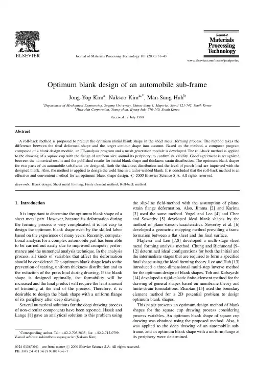
Optimum blank design of an automobile sub-frameJong-Yop Kim a ,Naksoo Kim a,*,Man-Sung Huh baDepartment of Mechanical Engineering,Sogang University,Shinsu-dong 1,Mapo-ku,Seoul 121-742,South KoreabHwa-shin Corporation,Young-chun,Kyung-buk,770-140,South KoreaReceived 17July 1998AbstractA roll-back method is proposed to predict the optimum initial blank shape in the sheet metal forming process.The method takes the difference between the ®nal deformed shape and the target contour shape into account.Based on the method,a computer program composed of a blank design module,an FE-analysis program and a mesh generation module is developed.The roll-back method is applied to the drawing of a square cup with the ¯ange of uniform size around its periphery,to con®rm its validity.Good agreement is recognized between the numerical results and the published results for initial blank shape and thickness strain distribution.The optimum blank shapes for two parts of an automobile sub-frame are designed.Both the thickness distribution and the level of punch load are improved with the designed blank.Also,the method is applied to design the weld line in a tailor-welded blank.It is concluded that the roll-back method is an effective and convenient method for an optimum blank shape design.#2000Elsevier Science S.A.All rights reserved.Keywords:Blank design;Sheet metal forming;Finite element method;Roll-back method1.IntroductionIt is important to determine the optimum blank shape of a sheet metal part.However,because its deformation during the forming process is very complicated,it is not easy to design the optimum blank shape even by the skilled labor based on the experience of many years.Recently,computa-tional analysis for a complex automobile part has been able to be carried out easily due to improved computer perfor-mance and the numerical analysis technique.In the analysis process,all kinds of variables that affect the deformation should be considered.The optimum blank shape leads to the prevention of tearing,uniform thickness distribution and to the reduction of the press load during drawing.If the blank shape is designed optimally,the formability will be increased and the ®nal product will require the least amount of trimming at the end of the process.Therefore,it is desirable to design the blank shape with a uniform ¯ange of its periphery after deep drawing.Several numerical solutions for the deep drawing process of non-circular components have been reported.Hasek and Lange [1]gave an analytical solution to this problem usingthe slip-line ®eld-method with the assumption of plane-strain ¯ange deformation.Also,Jimma [2]and Karima [3]used the same method.V ogel and Lee [4]and Chen and Sowerby [5]developed ideal blank shapes by the method of plane-stress characteristics.Sowerby et al.[6]developed a geometric mapping method providing a trans-formation between a ¯at sheet and the ®nal surface.Majlessi and Lee [7,8]developed a multi-stage sheet metal forming analysis method.Chung and Richmond [9±12]determined ideal con®gurations for both the initial and the intermediate stages that are required to form a speci®ed ®nal shape using the ideal forming theory.Lee and Huh [13]introduced a three-dimensional multi-step inverse method for the optimum design of blank shapes.Toh and Kobayashi [14]developed a rigid±plastic ®nite-element method for the drawing of general shapes based on membrane theory and ®nite-strain formulations.Zhaotao [15]used the boundary element method for a 2D potential problem to design optimum blank shapes.This paper presents an optimum design method of blank shapes for the square cup drawing process considering process variables.An optimum blank shape of square cup drawing was obtained using the proposed method.Also,it was applied to the deep drawing of an automobile sub-frame,and an optimum blank shape with a uniform ¯ange at its periphery weredetermined.Journal of Materials Processing Technology 101(2000)31±43*Corresponding author.Tel.: 82-2-705-8635;fax: 82-2-712-0799.E-mail address :nskim@ccs.sogang.ac.kr (Naksoo Kim)0924-0136/00/$±see front matter #2000Elsevier Science S.A.All rights reserved.PII:S 0924-0136(99)00436-72.Design of optimum blank shapeThe de®nition of the optimum blank shape is the mini-mization of the difference between the outer contour of the deformed blank and the target contour that indicates the residual ¯ange of uniform size around the periphery of the product.The target contour is generated from the outer contour of the product and determines an optimum blank shape using the results of ®nite-element simulation with the roll-back method.In the process of blank design the simula-tion is performed using an explicit ®nite-element software PAM-STAMP and the interface program is developed for con-necting the blank design module,the remeshing module,the post-processor module and the FE-analysis package.2.1.Roll-back method`The roll-back method starts by de®ning the target con-tour.After determining the length of the ¯ange that remains around the periphery of the product,the pro®le of the target contour is created by offsetting an equal distance from the outer contour of the product and its mesh system is gener-ated by beam elements.The process of blank design is illustrated in Fig.1.The mesh system of the prepared square blank for initial analysis is shown in Fig.1(a).After an analysis,the mesh system of the deformed blank and the target contour are shown in Fig.1(b).At the ¯ange of the deformed blank,a distinction is made between the interior ¯ange within the target contour and the exterior ¯ange out ofthe target contour.The ¯ange out of the target contour is the part that will be trimmed and the ¯ange within the target contour is the part which does not keep shape is due to the incompletion of the blank shape.Thus the modi®ed blank shape should be designed to take the shape of the outer contour of the product completely.The contour of the modi®ed blank shape using the roll-back method and the initial blank shape is shown in Fig.1(c).The mesh system of the modi®ed blank shape for FE-analysis is shown in Fig.1(d).The blank design method will be introduced in detail.The quarter of the deformed blank and the target contour are shown in Fig.2(a).According to the previous explanation,the remained ¯ange can be divided into the interior and the exterior ¯ange.The design process of region A is shown in Fig.2(b).In the mesh of the deformed blank a square grid IJKL on the target contour will be considered,and then the internal dividing point Q in will be calculated at the ratio of m tonFig.1.Illustrating the process of ®nding the optimum blank:(a)initial blank shape;(b)deformed blank and target contour;(c)roll-back blank and contour;(d)modi®ed blankshape.Fig.2.The roll-back process of a mesh located on the surface of the ¯ange:(a)a mesh located on the surface of the ¯ange;(b)region A:residual drawing part out of target contour;(c)region B:residual drawing part inside the target contour.32J.-Y.Kim et al./Journal of Materials Processing Technology 101(2000)31±43between the node J and K.This point is mapped back into the mesh system of the initial blank.The internal dividing point Q H in is calculated at the ratio of m to n between the same node J H and K H.The following process is performed on the element of the deformed blank on the target contour.The describing point of the outer contour of the modi®ed blank shape can be calculated.If the coordinates of the nodes J and K are J(x1,y1),K(x2,y2)and the coordinates of the nodes J H and K H are J H x H1Y y H1 Y K H x H2Y y H2 ,the ratio of m to n ism X n JQJKX QKJK(1)The coordinate of the internal dividing point Q H in can be expressed asQ H inmx H2 nx H1m nYmy H2 ny H1m n(2)The design process of region B is shown in Fig.2(c).In the mesh of the deformed blank a square grid MNOP of which the outward edge crosses the target contour should be considered,and then the external dividing point Q out can be calculated at the ratio of m to n between nodes O and P.This point is mapped back into the mesh system of the initial blank.The external dividing point Q H out can be calculated at the ratio of m to n between the same nodes Q H and P H.If the coordinates of the nodes O and P are O(x1,y1),P(x2,y2)and the coordinates of the O H and P H are O H x H1Y y H1 Y P H x H2Y y H2 ,the ratio of m to n ism X n OQOPX QPOP(3)The coordinate of the external dividing point Q H out can be expressed asQ H outmx H2Ànx H1Ymy H2Àny H1(4)The following process is performed on all the element of the deformed blank related on the target contour.The points describing the outer contour of modi®ed blank shape can be calculated.When all points of two cases are connected by the spline,the outer contour of modi®ed blank can be described.This process is shown in Fig.3.2.2.The development of the optimum blank design programTo optimize the initial blank shape,a design program was developed following the prescribing method and procedures. This program consists of the blank shaper design module, the mesh generation module and the post-processor module. The whole procedure is illustrated in Fig.4.To perform the design process of a blank shape,an interface module is needed.This module is developed to read the output®le of ®nite-element analysis and design the optimum blank shape and generate the input®le.3.Designs of blank shape and application3.1.Blank design of a square cupTo verify the validity of the roll-back method,it is applied to the process of square cup deep drawing.Several numerical solutions of the deep drawing process for non-circular components have been reported recently.The pub-lished blank shapes by Lee and coworkers[16±18]are compared with the resultusing the roll-back method.The Fig.3.Flowchart of the blank design module.Fig.4.Flow chart of the main program.J.-Y.Kim et al./Journal of Materials Processing Technology101(2000)31±4333dimensions of the die and punch set for an analysis are shown in Fig.5.The material of the sheet metal is cold-rolled steel for an automobile part.The following are the material propertiesand process variables.Stress±strain relation:"s58X 78Â 0X 00003 "e0X 274 kgf a mm 2 ;Lankford value:"R 1X 679;initial blank size:160mm Â160mm square blank;initial thickness:t 0.69mm;friction coef®cient:m 0.123;and blank-holding force:4000kgf (1kgf 9.81N).The deformed shapes of the square cup obtained from the initial blank and the optimum blank are shown in Fig.6.Inthe present work the optimum blank shape for a square cup that is of 40mm height and 5mm width of ¯ange will be determined.Each modi®ed blank shape after the application of the roll-back method is illustrated in Fig.7.When an 160mm Â160mm square blank is used for an initial blank the outer contour of deformed blank is shown in Fig.7(a).A ®rst modi®ed blank shape can be calculated with the result of the initial square blank.An analysis result is shown in Fig.7(b).The difference between the deformed shape and the target contour is signi®cant.If the blank design process is repeated several times the difference decreases and con-verges to zero.Hence a square cup with a uniform ¯ange at its periphery can be made.The comparison between the ®nal result and a published result is shown in Fig.8.In the transverse direction the optimum blank shape using the roll-back method is larger than the published result.The load±displacement curves in square cup drawing process with various initial blank shapes are shown in Fig.9.As the modi®cation is repeated,the gap of the load±displacement curves before and after iteration decreases.Thus after the third modi®cation the maximum value of the load becomes the mean value between that of the ®rst and second modi®cation.After three modi®cations the optimum blank shape is determined,then the result with the optimum blank shape is compared with results in the literature.The thickness strain distribution in the diagonal direction is shown in Fig.10(a),whilst the thickness strain distribution in the transverse direction is shown in Fig.10(b).In the thickness strain distribution the result using the roll-back method is slightly different from the published result,but the overall strain distributions are quite similar.It is thus veri®ed that the roll-back method is a useful approach in the design of optimum blank shapes.3.2.Blank design of the left member of a front sub-frameAn analysis for members of a box-type front sub-frame is performed.The left member is selected as one of the subjects for analysis because its shape is shallow but complex.Fig.11shows the manufacturing set-up as modeled for the numer-ical simulation.The left member requires a uniform ¯ange for the spot welding between the upper and the lower parts besides the improvement of formability.It is recommended that the length of uniform ¯ange is 30mm.The target contour is de®ned at the position which is 30mm from the outer contour of product and is shown in Fig.12.Its mesh system is generated by beam elements.The material of the sheet metal is SAPH38P,a hot-rolled steel for automobile parts.The following are the material properties and process variables.Stress±strain relationship:"s 629Â"e 0X 274(MPa);Lankford value:"R1X 030;initial thickness:t 2.3mm;friction coef®cient:m 0.1;blank holding pressure:1MPa.Fig.5.Geometrical description of the tooling for the deep drawing of a square cup (dimensions:mm).Fig.6.The deformed shape of square cups with FE-mesh geometry where the cup height is 40mm:(a)deformed shape of the square cup obtained from the initial blank;(b)deformed shape of the square cup obtained from the optimum blank.34J.-Y.Kim et al./Journal of Materials Processing Technology 101(2000)31±43A hexagonal blank is used as the initial blank.After three modi®cations the optimum blank shape is determined.For this case,the load±displacement curves with various blank shapes are shown in Fig.13.The comparison of the initial ¯ange and the deformed ¯ange with various blank shapes is shown in Fig.14.As the modi®cation is repeated,the maximum punch load is reduced and the outer contour may be drawn to the target contour at the same time.The thickness distribution is improved step by step;the thickness distribution with various blank shapes being shown in Fig.15.The comparison between the optimum blank shape designed by the roll-back method and the blank shape for mass production is illustrated in Fig.16.The optimum blank shape shows curvature because the outer contour of the product and the ¯ow rate of the sheet metal are considered.However,the blank shape for mass production is simple and straight because the convenience of cutting is considered.To verify the result an initial blank cut by a laser-cutting machine was prepared.The ®nal shape drawn with the initial blank in the press shop isshownparison of the initial ¯ange shapes and the deformed ¯ange shapes:(a)initial square blank;(b)®rst modi®ed blank;(c)second modi®ed blank;(d)third modi®edblank.parison of the initial blank contour between the roll-back method and Huh's method.J.-Y.Kim et al./Journal of Materials Processing Technology 101(2000)31±4335in Fig.17.It had a ¯ange of uniform size around its periphery.The thickness distribution at the position of four sections in the longitudinal direction of the left member was mea-sured.Fig.18shows a comparison of thickness between the computed results and the experimental results in each sec-tion.In section A,the thickness distribution has some error at the end of the ¯ange,whilst in sections B and C,the computed results are compatible with the experimentalresults.In section D,the computed results predicted that a split might happen,but the experimental cup did notsplit.Fig.9.Load±displacement curves in the square cup drawing process with various initial blankshapes.Fig.10.Thickness strain distribution in a square cup:(a)diagonal direction;(b)transversedirection.Fig.11.FE-model for a sub-frame left member.36J.-Y.Kim et al./Journal of Materials Processing Technology 101(2000)31±43If the initial blank shape,the ®nal shape and thickness distribution are considered,the results predicted by the roll-back method has a good agreement with the experimental values.Therefore,as well as the roll-back method being applicable to a simple shape,it can be applied to a complex and large shape.3.3.Blank design of No.2member of front sub-frame An analysis of No.2member is performed,with its deep and complex shape.Its optimum blank shape is designed using the roll-back method.Fig.19shows the manufacturing set-up as modeled for the numerical simulation.Because its drawing depth is very deep,eccentricity may occur due to the blank initial position or shape.Thus the target contour is de®ned at the position that is 40mm from the outer contour of product and it is shown in Fig.20.A square blank is used as the initial blank.After three modi®cations the optimum blank shape isdetermined.Fig.12.Target contour for the leftmember.Fig.13.Load±displacement curves in the left member drawing process with various blankshapes.parison of the initial ¯ange shapes and the deformed ¯ange shapes:(a)initial blank;(b)®rst modi®ed blank;(c)second modi®ed blank;(d)third modi®ed blank.J.-Y.Kim et al./Journal of Materials Processing Technology 101(2000)31±4337Fig.15.Thickness distribution with various blank shapes (unit:mm):(a)initial blank;(b)®rst modi®ed blank;(c)second modi®ed blank;(d)third modi®edblank.parison of the initial blank shapes predicted by the roll-back method and those designed by skilled labor.38J.-Y.Kim et al./Journal of Materials Processing Technology 101(2000)31±43For this case,load±displacement curves for various blank shapes are shown in Fig.21,whilst a comparison of the initial ¯ange and the deformed ¯ange with various blank shapes in shown in Fig.22.The thickness distribution with the initial shape is shown in Fig.23,whilst the thickness distribution with the optimum blank shape is shown in Fig.24.The thickness distribution of the side-wall and of the ®llet connecting the side-wall to the top isimproved.Fig.17.Left member drawn in the press shop with the initial blank predicted by the roll-backmethod.Fig.18.(a)Sections for measuring the thickness distribution.(b±e)Thickness distributions at sections A±D,respectively.J.-Y.Kim et al./Journal of Materials Processing Technology 101(2000)31±43393.4.Design of the welding line with TWB analysis of No.2memberAfter designing the optimum blank shape of No.2member,a tailor-welded blank is applied to this member.To reduce the weight of the sub-frame,structural analysis is performed.On the area where the stress intensity level is low,it is proposed to reduce the thickness locally.Therefore,it is required to design a tailor-welded blank that makes a speci®ed shape after deformation.When two sheet metals of different thickness are welded together,their metal ¯ow is different from that of sheet metal of the same thickness.Thus it is dif®cult to design the location of the weld line.In this simulation the weld line is designed by the use of the roll-back method and the welding line should be located at the speci®ed position after deformation:the speci®ed position is 120mm on both sides of the centerline.Thus the target line is de®ned and meshed by beam elements.The outer contour of TWB and the welding line are shown in Fig.25,and the results are shown in Figs.26and 27.The welding lines can be reached to the target line but,on the top of the blank that has the lower thickness,fracture may occur.This is the same as the result that in the deep drawing of a tailor-welded blank with different thickness,failure occurred at the ¯at bottom of the punch parallel to the weld line.This is due to the deformation not beingdis-Fig.19.FE-model for the sub-frame leftmember.Fig.20.Target contour for the No.2member.Fig.21.Load±displacement curves in the No.2member drawing process with various blank shapes.40J.-Y.Kim et al./Journal of Materials Processing Technology 101(2000)31±43parison of the initial¯ange shapes and the deformed¯ange shapes:(a)initial blank;(b)®rst modi®ed blank;(c)second modi®ed blank;(d)third modi®edblank.Fig.23.Thickness distribution with the initial blank shape(unit:mm):(a)front view;(b)rearview.Fig.24.Thickness distribution with the optimum blank shape(unit:mm):(a)front view;(b)rearview.parison of the weld line between the initial blank shape andthe deformed blank shape.J.-Y.Kim et al./Journal of Materials Processing Technology101(2000)31±4341tributed uniformly,most of the stretching being concentrated on the side of the blank with lower strength.The process condition without fracture should be determined for the combination of the drawing depth and the two different thickness as shown in Fig.28.4.ConclusionsIn this paper the roll-back method that designs an opti-mum blank shape is proposed.Based on the method,a computer program composed of a blank design module,an FE-analysis program and a mesh generation module is developed and it is applied to the deep drawing of a front sub-frame.The results of the present paper are summarized as follows:1.To verify the validity of the proposed method it is applied to the deep drawing of a square cup.The outer contour may be drawn to the target contour.2.The roll-back method is applied to the optimum blank design of a left member of an automobile sub-frame.The thickness distribution and the load level are improved.When the initial blank shape,the ®nal shape and thickness distribution are compared,the results predicted by the roll-back method have a good agreement with the experimental results.It is concluded that this method can be applied to the deep drawing of the complex automobile parts.3.The analysis of No.2member with a tailor-welded blank is performed.The position of welding lines on the initial blank is designed.The roll-back method can be applied to the design of the welding line position.4.In most cases,the edge of blank takes the shape of the target contour within a few iterations,which shows that the roll-back method is an effective and convenient method for an optimum blank shape design.References[1]V .V .Hasek,nge,Use of slip line ®eld method in deep drawingof large irregular shaped components,Proceedings of the Seventh NAMRC,Ann Arbor,MI,1979,pp.65±71.[2]T.Jimma,Deep drawing convex polygon shell researches on the deepdrawing of sheet metal by the slip line theory.First report,Jpn.Soc.Tech.Plasticity 11(116)(1970)653±670.[3]M.Karima,Blank development and tooling design for drawn partsusing a modi®ed slip line ®eld based approach,ASME Trans.11(1989)345±350.[4]J.H.V ogel,D.Lee,An analysis method for deep drawing processdesign,Int.J.Mech.Sci.32(1990)891.[5]X.Chen,R.Sowerby,The development of ideas blank shapes by themethod of plane stress characteristics,Int.J.Mech.Sci.34(2)(1992)159±166.[6]R.Sowerby,J.L.Duncan,E.Chu,The modelling of sheet metalstamping,Int.J.Mech.Sci.28(7)(1986)415±430.[7]S.A.Majlessi,D.Lee,Further development of sheet metal forminganalysis method,ASME Trans.109(1987)330±337.[8]S.A.Majlessi,D.Lee,Development of multistage sheet metalforming analysis method,J.Mater.Shap.Technol.6(1)(1988)41±54.[9]K.Chung,O.Richmond,Ideal forming-I.Homogeneous deformationwith minimum plastic work,Int.J.Mech.Sci.34(7)(1992)575±591.[10]K.Chung,O.Richmond,Ideal forming-II.Sheet forming withoptimum deformation,Int.J.Mech.Sci.34(8)(1992)617±633.Fig.26.Deformed shape of No.2member with the tailor-weldedblank.Fig.27.Deformed shape of No.2member with the tailor-welded blank:(a)front view;(b)rearview.Fig.28.Thickness distribution with the tailor-welded blank (unit:mm):(a)front view;(b)rear view.42J.-Y.Kim et al./Journal of Materials Processing Technology 101(2000)31±43[11]K.Chung,O.Richmond,Sheet forming process design based onideal forming theory,Proceedings of the Fourth International Conference on NUMIFORM,1992,pp.455±460.[12]K.Chung,O.Richmond,The mechanics of ideal forming,ASMETrans.61(1994)176±181.[13]C.H.Lee,H.Huh,Blank design and strain prediction of automobilestamping parts by and inverse®nite element approach,J.Mater.Process.Technol.63(1997)645±650.[14]C.H.Toh,S.Kobayashi,Deformation analysis and blank design insquare cup drawing,Int.J.Mech.Tool Des.Res.25(1)(1985)15±32.[15]Z.Zhatao,L.Bingwen,Determination of blank shapes for drawingirregular cups using and electrical analogue methods,Int.J.Mech.Sci.28(8)(1986)499±503.[16]H.Huh,S.S.Han,Analysis of square cup deep drawing from twotypes of blanks with a modi®ed membrane®nite element method, Trans.KSME18(10)(1994)2653±2663.[17]C.H.Lee,H.Huh,Blank design and strain prediction in sheet metalforming process,Trans.KSME A20(6)(1996)1810±1818. [18]C.H.Lee,H.Huh,Three-dimensional multi-step inverse analysis foroptimum design of initial blank in sheet metal forming,Trans.KSME A21(12)(1997)2055±2067.J.-Y.Kim et al./Journal of Materials Processing Technology101(2000)31±4343。
( 1. Faculty of Civil Engineering & Geosciences, Delft University of Technology , P. O. Box 5048,2600 GA Delft, t he Nether lands; 2. Key Laboratory of Silicate Materials Science and Engineering of the Ministry of Education, Wuhan University of Technology, Wuhan 430070, China)Abstract: Coal tar, a by- product from the destructive distillation of coal in co king oven, is widely used in road engineering for its excellent adhesion and fuel resistance properties, especially for pavement surface treatments in gas stations and airports.However, coal tar has a high Poly cyclic Aromatic Hydro carbons ( or PAHs) content, which makes it toxic.I n 1985, the International Agency for Research on Cancer ( IARC) has proved that coal tar is carcinogenic to humans. Research showed that Coal Tar- based Sealers ( CTS) contribute to the majority of PAHs pollution in the water environment. Because of this environmental concern, CT S are not allowed in many dev eloped countries in the USA and Europe. In contrast, coal tar is still used for road engineering in China and is even used increasingly .This paper gives a literature review on the general information and research about environmental concern of using coal tar in road engineering. Based on the review , some possible alternatives to replace coal tar are described. These alternatives include nanoclay/ epoxy modified bitumen/ bitumen emulsion and waterborne polyuret hane/ epoxy resin, which are environmental friendly. They have the potential to perform as w ell as CTS, and even better in some special applications.Key words:coal tar; pavement surface treatment; adhesion property; poly cyclic aromatic hydrocarbons; modified bitumen emulsionCLC number: U 416 Document code: A Article ID: 1671- 4431( 2010) 17- 0001- 07Received date: 2010- 05- 07.Biography : Xiao Y( 1986- ) , Ph D Candidate. E-mail: yue. xiao@1 introductionTwo basic types of binders are currently used in the pavement surface treatment market: coal tar-based and bitumen-based. At some places like g as stat ions and airports, coal tar-based surface sealers performed much better than bitumen-based sealers with regards to adhesion properties and chemical resistance. Coal tar-based have better resistance to petroleum oils and inorganic acids, and have better moisture resistance[ Austin, 2005] .Because of these out standing properties, CTS are widely used in road engineering for pavement surfacetreatment for many years. However, coal tar is a complex hydrocarbon mixture consisting of hundred of PAH[SCHER, 2008] . These PAHs are toxic and considered human carcinogens. Because of it s environmental unfriendly properties, coal tar is not allowed in most of the developed counties like the Netherlands. In the Netherlands,use of tar containing product s is not allowed since 20 years, with one temporary except ion for antiskid runways in airfields [ van Leest , 2005] . But after 2010, it w ill not be allowed for airport pavement application anymore. Compared to these bans, coal tar is still used for road engineering in China. China Coal Tar Industry Report mentioned that the coal tar consumption w ill be on the upward t rend [CCTIR, 2008] .Based on new technologies like nano technology and two-component technology, other materials are developed for pavement surface treatment and they perform w ell. Modified bitumen emulsions, which can be applied at low temperatures, were successfully used in South Africa, Australia and many other countries. Additives such as polymers ( SBS, SBR and EVA ) , clays ( illite, kaolinite and montmorillonite ) are known to improve the properties of bitumen emulsions in special road applications [ TRB-EC102, 2006;Xiao, 2010] . With the waterborne two-component technology, coating manufacturers can producehigh-performance sealers and achieve the same or better properties than solvent-based sealers. Furthermore, waterborne resins for coating s usually do not contain or just contain a small amounts of other solvent s, indicating that waterborne two component systems are environmental friendly. Epoxy modified bitumen w as originally developed in the late 1950s by Shell Oil Company as a material designed to withstand fuel exposure [ Thom, 2006] . After full curing , epoxy modified bitumen mixture has high temperature stability and strength, excellent fatigue, superior adhesion and rutting resistance.In this paper, a short literature review is given on the use and properties of CTS for pavement surface treatment and its environmental concern. After that several possible alternatives are discussed, such as nanoclay modified bitumen emulsion, epoxy modified bitumen, waterborne polyurethane/ epoxy resin. These alternatives may have good properties and are environmental friendly.2 Use and Advantages of Coal Tar Based SealersCoal tar-based products are used in many industries, for example pavement engineering, the building industry and medical treatment s. In pavement engineering , one of the largest applications is CTS.Coal tar can be used as a binder and filler in surface treatment formulations, and as a modifier for epoxyresin surface coating s. T he streets of Baghdad w ere the first to be paved with tar from the 8th century AD. Tar was a vital component of the first sealed, or tarmac roads. The first tar macadam road with a tar-bound surface was placed in 1848 out side Nottingham, England. In Washington D. C. some of thetar-bound surface courses have a service life of about 30 years.Coal tar is a very complex mixture of chemicals. It s molecular structure is quite different from bitumen.Some of the constituents are described as PAHs. Being stable in molecular structure, these chemicals are incompatible with oil and gas, and provide a barrier coat to protect asphalt surfaces against the destructive effects of petroleum based products and chemicals [Aust in, 2005] . CTS have a better chemical resistance than bitumen based, extremely low permeability to moisture and a high resistance to ultraviolet radiation. These properties make it ideally suited for parking areas w here concentrations of oil and gasoline leaks are prevalent, like gas stations, truck and bus terminals and airport s. CTS are used to extend the life and reduce maintenance cost associated with asphalt pavements, primarily in asphalt road pavement. They are typically used at airports for aprons, taxiways and runways. The Federal Aviation Administration Advisory Circular 150/ 5370-10A Standards for Specifying Construction of Airports include a requirement for pavement sealers that they should contain at least 35% coal tar in runway asphalt pavement.The reason for this requirement is that CTS have a much better resistance to jet fuel than bitumen-based sealers [Austin, 2005].3 Environmental ConcernGenerally, coal tars consist of a mixture of many organic compounds, like benzene, toluene, phenol, naphthalene, anthracite , and others. The risk assessment of coal tar is largely based on PAHs, especially on Benzo (a) pyrene . PAHs are the most relevant component s in terms of toxicity in coal tarproducts[ SCHER, 2008] .3. 1 Polycyclic aromatic hydrocarbonsPolycyclic aromatic hydrocarbons are also known as polycyclic aromatic compounds, polyaromatic hydrocarbons or as polynuclear aromatics. PAHs are a group of over 100 different chemicals consisting of carbon and hydrogen in fused-ring structures. T able 1 shows several typical chemical structures of PAHs. PAHs are highly toxic and harmful to human and ecosystem health [Austin, 2005] . The content of PAHs in coal tar increases as the carbonization temperature increases.3.2 Environmental riskIn 1985, IARC has pointed out that coal tar pitches are carcinogenic in humans [IARC, 1985] . In 2008,three scientific commit tees ( SCCP, the Scientific Commit -tee on Consumer Products; SCHER, the Scientific Committee on Health and Environmental Risks; SCEN IHR, the Scientific Commit tee on Emerging and NewlyIdentified Health Risks) concluded that cancer risk was the most serious point of coal tar s risk characterizations [ SCHER, 2008] . Occupational exposure to coal tar increases the risk of developing skin cancer and other tissue sites , like lung, bladder, kidney and digestive tract . According to the IARC, products that include more than 5 percent of crude coal tar are Group 1 carcinogen which has sufficient evidence of carcinogenicity in humans. So, many countries all over the world have eliminated it s usage.In 2003, scientist s from the city of Austin ( USA ) identified CTS as a significant source of PAHs contamination. The United States Geological Survey and Austin City have conducted additional research that corroborates this finding, concluding that coal tar sealants are responsible for the majority of PAHs pollution in water environment in the Austin area. Coal tar-based pavement sealers are considered as a source of urban water pollution. These are long-lasting substances that can build up in the food chain to harmful levels to humans. Based on their investigations, Austin became the first city in the USA to ban the use of CTS for pavements [ Austin,2005; Mahler, 2005] .As a precaution, in Germany, manufacturers have voluntarily agreed to ban coal tar from their product s. In the Netherlands, coal tar containing products did not meet the Dutch Environmental Standards and w ill not be allowed for airport pavement after 2010.4 Possible AlternativesAccording to these environmental concerns, alternatives are required. These alternatives should have atleast comparable or better properties than CTS. At the same time, they should be environmental friendly. In this section, the possible use of modified bitumen emulsions, epoxy modified bitumen and waterborne resins are discussed.4. 1 Modified bitumen emulsionsBitumen emulsions are heterogeneous systems with two or more liquid phases, consisting of a continuous liquid phase ( water ) and at least one second liquid phase ( bitumen) dispersed in the former as fine droplets [ TRB-EC102, 2006] . Standard bitumen emulsions are normally considered to be of the oil in water type and contain from 40% to 75% bitumen, 0. 1% to 2. 5% emulsifier, 25% to 60% water plus some minor components. The bitumen droplets rang e from 0. 1 to 20 micron in diameter.4. 1. 1 Properties of modified bitumen emulsionsUnlike bitumen, bitumen emulsions do not need to be heated at high temperatures before application. Temperature storage and application at ambient temperature can avoid the use of energy and emissions associated with heating and drying [Kennedy, 1997]. This makes bitumen emulsions more economic and environmental friendl , compared to coal tar-based products.Additives are used to improve the properties of bitumen emulsions in special road applications. Polymer( SBS, SBR and EVA) , clay illite , kaolinite and montmorillonite and epoxy modified bitumen/ bitumen emulsions were successfully used in South Africa and Australia [ TRB-EC102, 2006; Xiao, 2010] .During the application of bitumen emulsion, the water must be separated from the bitumen phase and evaporate.This separation is called breaking. After complete evaporation of the water, the bitumen particles will coalesce and bond together to develop mechanical properties. This strength development is curing.4. 1.2 nanoclay modified bitumen emulsionThe most preferred and widely used nanoclays are organically modified smectite clays with a 2: 1-type layey structure such as montmorillonite, saponite, etc [ Ammala , 2007] . All these layered silicates have the same crystalline structure and normally have a thickness of about 1 nanometer and a length of about 50 ~ 1 000 nanometers.In nanoclay modified bitumen emulsion, three possible particle dispersions can be distinguished as Fig. 1 shows [Xiao, 2010]. In the case of type one (see Fig. 1( a) ) , all the nanoclay particles are dispersed in the bitumen droplets. In this case, after breaking and curing the particles are dispersed in the binder between the aggregates. In the second type (see Fig. 1( b) ) , all of the nanoclay particles are dispersed in the water phase. After breaking and full curing, the particles are surrounding at the boundaries of the bitumen droplet s. The third type( see Fig. 1( c) ) is a combination of the first two types. Some of the particles are dispersed in the bitumen droplets while the others are dispersed in the water phase. In this condition, after breaking and curing the nanoclay particles both occur in the binder and between the bitumen droplets.These dispersion types have a significant influence on the properties of bitumen residues. Further investigations need to be carried on for checking these dispersions.Fig . 2 shows the possible outstanding properties of nanoclay modified bitumen emulsion on outside chemical resistance [Xiao, 2010] . With the unmodified bitumen emulsion after curing on the pavement surface, fuel, moisture and ultraviolet radiation can affect the binder directly. These can decrease the performance and cause raveling and ageing problems. When nanoclay modified bitumen emulsions are used for surface treatment, four steps can be dist inguished during breaking and curing. First, nanoclay modified bitumen emulsion consist s mainly of water, bitumen drop and nanoclay layers. Second, the water phase evaporates during the breaking and curing process. Then, bitumen droplets adhere to nanoclay particles, causing clusters to form the binder. At the last, binder is formed with nanoclay layers inside.The dispersed nanoclay particles can decrease surface damages due to fuel, moisture, air, etc. to a certain extent, resulting in better chemical and ageing resistance.4.2 Epoxy modified bitumensThe epoxy modified bitumen binder is a two phase chemical system in which the continuous phase is an acid cured epoxy and the discontinuous phase is a mixture of specialized bitumens, which makes the mixture performdifferent from a traditional asphalt mixture.4. 2. 1 Properties of epoxy modified bitumensEpoxy modified bitumen was used for pavement treatment long time ago and has achieved better properties than unmodified bitumen. In 1967, it was used to strengthen the surface of San Francisco Bay smile-long San Mateo-Hay ward Bridge. After more than 40 years, the bridge surface is reported to be in excellent condition.The special structure of epoxy modified bitumen makes it perform different from traditional bitumen. It does not become brittle at low temperature and does not melt at high temperature. Epoxy modified bitumen is a flexible material that can be applied in thin surface layers. When used on roads, it sets quickly enough to allow early traffic even before full curing, which enables the road to be reopened withintwo hours [ Xiao, 2010] .Epoxy modified bitumen is reported to be extremely durable as w ell as flexible. Surfaces with epoxy modified bitumen obtained better skid resistance and produce less noise than bitumen based sealers. Epoxy modified bitumen has extremely high temperature stability and strength, superior rutting resistance, excellent adhesion properties, high resistance to surface abrasion and is sufficiently fuel resistance [ Elliot t, 2008; Xiao, 2010] .4.2.2 Two-component epoxy modifiedbitumenTwo-component epoxy modified bitumen is acold mix application material. It is a two componentreactive material based on two components. One is amix of bitumen, bitumen-compatible epoxides andadditives. The other one is a mix of hardeners. After mixing of these two component s, there will be a fast react ion leading to epoxy resin within a bitumen based matrix.The tensile strength of Esha Seal 2C, which is a kind of two-component epoxy modified bitumen, obtained from ICOPAL BV, was evaluated using the Direct T ensile Test . Fig. 3 shows the tensile strengthafter different curing times and temperatures.Results indicate that the curing rate of epoxy modified bitumen emulsion depends on the curing temperature. The tensile strength increases with increasing curing time temperature . The tensile strength after full curing is higher than thetensile strength of bitumen, which implies that roads can be reopened for traffic very quickly w hen epoxy modified bitumens are applied in the surface layer.4. 3 Waterborne resinsWaterborne resins use water as the main volatile liquid component . It always shows good adhesion and the resistance to fuel, water and chemical is good. New technologies in waterborne systems provide unique technical solutions to get good properties, such as good adhesion to concrete and acidic resistance. With the waterborne two-component technology, coating manufacturers can formulate high-performance coatings without a cosolvent and achieve the same or better properties. Here waterborne polyurethane and epoxy resins will be discussed.4. 3. 1 Waterborne polyurethane resinsPolyurethane is a polymer consisting of a chain of organic units joined by urethane carbamate links. Polyurethane resins are formed from the reaction of an isocyanate with compounds containing active hydrogen, as Fig.4 shows. When the two components are mixed the hydroxyl groups ( - OH) in the resin react with the isocyanate groups ( N=C=O) in the hardener and a three dimensional molecular structure is produced[Weiss, 1997] .Because only one isocyanate group can react with one hydroxyl group, it is possible to vary the ratio of hydroxyl groups and isocyanate groups slightly either w ay in order to modify the mechanical properties of the system.Basically, waterbornepolyurethanes can be described asreactive or non-reactive polymerscontaining urethane and urea groupswhich are stabilized in water byinternal or external emulsifiers. Thesedifferent hydrophilic modify cationsallow the production of stablewaterborne polyurethanes with average particle sizes between 10 nm and 200 nm. Waterborne polyurethane resin is a water-based aliphatic polyurethane emulsion.Waterborne polyurethanes are environmental friendly. They provide a tough, durable and highly flexible binder. The advantages associated with polyurethane coatings are their high tensile strength, excellent adhesion properties and chemical/ mechanical resistance. Properties of waterborne polyurethanes can be improved by adding modifiers, such as organoclay layers [ Kim, 2003; Xiao, 2010] .Addagrip 1000 System resin is a two-component polyurethane resin designed by Addagrip Surface Treatments UK Ltd. It can be used for sealing to protect asphalt surfaces from erosion caused by frostdamage, chemical at tack and aviation fuel spillage. Areas treated over the last twenty years at military and civil air fields have prevented further deterioration and increased the service life of the concrete pavement by an estimated 10~ 15 years. Table 2 show s the properties of the samples before and after surface treatment with Addagrip 1000 System resin. 10 cm x 10 cmx10 cm blocks w ere used. The sample surfaces w ere heated and dried by a hot compressedair system before the resin w as sprayed onto the surface [Addagrip Ltd. ] . After surface reatment with this kind of polyurethane resin, the water and fuel resistance can be improved significantly.4. 3. 2 Waterborne epoxy resinsEpoxy is a copolymer. It is formed from two different chemicals, the resin and the hardener. Most common epoxy resins are produced from a reaction between Epichlorhydrin and bispheno-l A, see Fig.5[Weiss,1997] .Waterborne epoxy resin, with excellent adhesion properties, is another possible alternative. Waterborne epoxy resin is a stable resin material prepared by dispersing epoxy resin in the form of particles or droplet s into the dispersion medium based on water as a continuous phase.Application ofwaterborne epoxy resinsis not onlyconvenient but alsocauses no pollution tothe environmentand no harm to thehuman body. Afteradding a properamount of curing/ solidifying agent, advantages like high strength ,high-temperature resistance, chemical resistance, fatigue resistance, and high antiaging ability can be achieved [ Xiao, 2010; Weiss, 1997]5 ConclusionCTS are widely used for pavement surface treatments because of their excellent adhesion properties and good fuel resistance. How ever, because of their high PAHs content s, which are considered as human carcinogens, CTS are not allowed anymore in some of the developed counties. In order to eliminate the significant threat of pollution to our environment, w e should stop using CTS. Instead, modified bitumen emulsions, epoxy modified bitumen, waterborne polyurethanes and waterborne epoxy resins could achievecomparable or better properties than CTS. All of them have good adhesion, excellent chemical and ageing resistance. Epoxy modified bitumen has extremely high temperature stability and strength. Application of waterborne resins is convenient and the curing rate can be easily adjusted by changing the ratio of chemical components. And, the most important, these alternatives are environmental friendly.AcknowledgementsThe scholarship from the China Scholarship Council is acknowledged. T he authors would like to express thanks to ICOPAL BV for their materials and technical supports.References[1] AddagripLtd.www .adda grip [2] Ammala A, Hill A J.Poly( M-Xylene Adipamide)-Kaolinite and Poly( M-XyleneAdipamide)-Montmorillonite Nanocomposites [J] . Journal of Applied Polymer Science, 2007(104):1377- 1381.[3] Austin. http: / /www .ci. austin. tx . us/ watershed/ coaltar- ban. htm. Austin Bans Use of Coal Tar Sealants-first in Nation,2005.[4] CCTIR.China Coal Tar Industry Report 2006-2010.[R],2008.[5] Elliott R. 2008. Epoxy Asphalt: Concept and Properties. Workshop of TRB 2008.[6] IARC. Polynuclear Aromatic 4 Bitumens , Coal Tars and Der ived Products,Shale Oils and Soots. IARC Monographs on the Evaluation of Carcinogenic Risk of Chemicals to Humans,Vol. 35. Lyon, France:International Agency for Research on Cancer,1985.[7] Kennedy J. Alter native Materials and Techniques for Road Pavement Construction[R] . London: DOE Energy Efficiency Office,1997.[8] Kim B K, Seo J W, Jeong H M. Morphology and Properties of Waterborne Polyurethane/ clay Nanocomposite [J]. European[9] SCHER. Scientific Committee on Health and Environmental Risks. Coal tar pitch, high temperature Human Health Part. CAS No: 65996- 93- 2. EINECS No: 266- 028-2.[10] Thom N H. Asphalt Cracking: A Nottingham Perspective [J].Engenaria Civil/ Civil Engineering, 2006(26) : 75- 84.[11] TRB-EC102. Asphalt Emulsion Technology. Transportation Research Board[S], 2006.[12] Van Leest A J, Gaar keuken G. The F O D. Resistance of Sur face Layers on Airfields in the Netherlands; in Situ and Laboratory Testing [R] . 2005 European Airport Pavement Workshop, 2005. [13] Van Metre P C, Mahler B J. Trends in Hydrophobic Organic Contaminants in Urban and Reference Lake Sediments Across the United States, 1970- 2001[J]. Environmental Science and Technology,2005, 39( 15) : 5567- 5574.[14] Weiss K D. Paint and Coatings: A Mature Industry in Transition [J].Progress in Polymer Science, 1997, 22(2):203- 245.[15] Xiao Y. Literature Review on Possible Alternatives to Tar for Antiskid Layers . Delft University o f Technology, Road and Railway Engineering Section[R] . Report No.7-10-185-1,the Nether lands.。
毕业设计(论文)英文翻译及原文课题名称:基于Flexsim的城市生活垃圾收运路径仿真研究学院 : 旭日工商管理学院专业:物流管理姓名:董继超 __ 学号:080750517指导教师:贾永基二0一一年十二月六日英文翻译文章用于餐厅垃圾回收过程中的堆肥和热水解之间的环境负担比较1. 环境科学与工程系,清华大学,北京100084,中国摘要:近年来,在中国政府积极地态度和一些有效的餐馆垃圾管理下,餐馆垃圾回收有了显著的发展.为了评价餐馆垃圾回收对环境的影响,生命周期评估(LCA)比较了两个回收过程—堆肥和热水解- 估计能源消耗和污染物排放。
结果表明,有效的过程,在每个影响的类别不同,进行了评估,堆肥对全球变暖有更大的影响,达到了337.7公斤的二氧化碳相当量/公斤。
相比之下,由于能耗大,热水解中对生态毒性施加的影响更大。
但是,总的来说,热水解对环境的影响相对于堆肥来说只有65%,减少了对其他三个的影响:酸雨,富氧化和全球变暖。
显然,热水解是一种很有效的减少环境压力的回收方法.关键词:堆肥;热水解;环境负担;餐厅垃圾;生命周期评估1.引言随着中国加速城市化的可持续发展和人民生活水平的提高,餐饮垃圾已经变成都市固体废物的重要组成部分,约占50—70%.在北京,餐厅垃圾的日常产量已达1200吨.餐厅垃圾,可以诱发腐烂废物收集和运输,降低效率储存,输送,切碎和分离;引进在焚化过程中的水分和Cl;导致有气味的化合物的排放;从垃圾填埋场渗滤液的质量产生不利影响,已成为严重的环境问题。
在北京餐厅垃圾中的37%是都市固体废物(MSW),其合适的管理方法已成为在过去十年中最活跃的辩论问题。
许多技术,如崩溃,堆肥,利用来对待餐厅垃圾发酵等。
然而,在个别技术研究越来越感兴趣,目前已经在研究.根据北京餐厅垃圾对环境的看法做出综合评价。
在这项研究中,根据实际设施的运行参数,我们选择了两个典型的回收方法,在系统中以一吨餐厅的垃圾作为一个单位来考虑。
XXXX大学本科毕业设计(论文)外文翻译原文:How Visual Studio .NET Generates SQL Statements forConcurrency ControlAuthor: Steve SteinVisual Studio TeamAbstract: This paper examines the SQL statements Visual Studio® .NET generates for different kinds of concurrency control, how to modify them for better performance, and how to generate a statement that does not use concurrency control. (5 printed pages).IntroductionAny application that might have multiple users simultaneously attempting to access and modify data needs some form of concurrency control. Otherwise, one user's changes could inadvertently overwrite modifications from other users. The design tools in Visual Studio .NET can create SQL statements that use the "check all values" approach to optimistic concurrency or the "last-in wins" approach to updating data. This paper will explain:∙How each of these statement types are generated.∙How to modify the generated SQL statement for better performance.PrerequisitesYou should have an understanding of:∙Fundamental data concepts, including datasets and data adapters. For more information, see Introduction to Data Access with .∙Concurrency control basics and the options available in Visual Studio .NET. For more information, see Introduction to Data Concurrency in .Where Are the SQL Statements?SQL statements are located in the CommandText property of command objects. SQL commands are automatically generated at design time when configuring data adapters, and at run time when using command builder objects. For more information, see Concurrency and Command BuilderObjets .before us have addressed overlay network programming issues. Even early overlay network Configuring Data Adapters∙Drag a data adapter from the Data tab of the Toolbox∙Drag a table from Server Explorer∙Modifying an existing adapter, by selecting a data adapter and clicking the Configure Data Adapter link at the bottom of the Properties window.Command Builder objects∙Command builder objects are created programmatically at run time. For more information, see (SqlCommandBuilder or OleDbCommandBuilder)Concurrency and Data AdaptersWhen configuring data adapters with the Data Adapter Configuration Wizard, you can decide whether to use optimistic concurrency for the generated Update and Delete statements.Considerations and Caveats∙Your data source must have a primary key in order for the SQL statements to be generated to use optimistic concurrency.∙When creating data adapters by dragging tables from Server Explorer, the data adapter creates Update and Delete statements that are automatically configured for optimisticconcurrency. If you do not want to use optimistic concurrency, you can reconfigure the dataadapter: Right-click the adapter and select Configure Data Adapter from the shortcut menu,then clear the Use optimistic concurrency option of the Advanced SQL Generation OptionsDialog Box. The wizard will recreate the statements without the additional code to check forconcurrency violations.∙When reconfiguring an existing data adapter, note that the advanced settings all revert to their default state. For example, if you cleared the Use optimistic concurrency option when theadapter was originally configured, it will automatically be selected if you reconfigure it, even if you do not access the Advanced SQL Generation Options dialog box.∙If you select the Use existing stored procedures option in the Choose a Query Type section of the Data Adapter Configuration Wizard, the option to use optimistic concurrency is notavailable. The stored procedures will execute as is, and any desired concurrency checkingmust be done within the stored procedure, or programmatically built into your application.。
毕业设计外文资料翻译题目FIR数字滤波器多级输送带的连续称量学院机械学院专业机械设计制造及其自动化班级学生学号指导教师二〇一四年三月十五日Measurement 40 (2007) 791–796 Continuous weighing on a multi-stage conveyorbelt with FIR filterRyosuke Tasaki , Takanori Yamazaki, Hideo Ohnishi ,Masaaki Kobayashi, Shigeru KurosuDepartment of Mechanical Engineering, Kyoto Institute of Technology, Japan Department of Mechanical Engineering, Oyama National College of Technology, 771 Nakakuki, Oyama 323-0806, JapanDepartment of Engineering, Shinko Co., Ltd., 4219-71 Takasai, Shimotsuma 304-0031, JapanResearch Institute, Crotech, JapanReceived 13 January 2006; received in revised form 23 March 2006; accepted 11 May 2006Available online 2 June 2006AbstractToday higher speed of operation and highly accurate weighing of packages during crossing a conveyor belt has been getting more important in the food and distribution industries etc. Continuous weighing means that masses of discrete packages on a conveyor belt are automatically determined in sequence. Making the proper use of new weighing scale called a multi-stage conveyor belt scale which can be created so as to adjust the conveyor belt length to the product length, we propose a simplified and effective mass estimation algorithm under practical vibration modes. Conveyor belt scales usually have maximum capacities of less than 80 kg and 140 cm, and achieve measuring rates of 150 packages per minute and more. The output signals from the conveyor belt scales are always contaminated with noises due to vibrations of the conveyor belt and the product in motion. In this paper digital filter of finite-duration impulse response (FEB) type is designed to provide adequate accuracy. The experimental results on conveyor belt scales suggest that the filtering algorithm proposed here is effective enough to practical applications. As long as spaces between successive products are set within a specified range, the products can be weighed correctly even if products having different lengths are transported in random manner.Keywords: Mass measurement; Continuous weighing; Conveyor belt; FIR filter* Corresponding author. Tel.: +81 285 20 2212; fax: +81 285 202884.E-mail addresses: yama@oyama-ct.ac.jp (T. Yamazaki),oonishi@vibra.co.jp (H. Ohnishi), mkobayas@vibra.co.jp (M.Kobayashi), kurosu_shi@yahoo.co.jp (S. Kurosu).1 Tel.: +81 296 43 2001; fax: +81 296 43 2130.2 Tel./fax: +81 296 28 4476.0263-2241/$ - see front matter© 2006 Published by Elsevier Ltd.doi:10.1016/j.measurement.2006.05.0101.IntroductionConveyor belt scales among these are most important for the production of a great variety of prepackaged products [1]. When a product is put on a conveyor belt, a measured signal from the conveyor belt scale is always contaminated by noises. Since the measured signal is usually in the lower frequency range, a filter which will effectively cut down noises at the high-frequency end can be easily designed. If, however, the product (like a cardboard box and a parcel etc.) has a low frequency component, where the noise intensity is high, it is practically impossible to separate the measured signal from noise. There still exist real problems for which engineering development in noise-filtering is needed.The recent techniques of dynamic mass measurement have been investigated to find a way to obtain mass of the product under dynamic conditions. The key idea of dynamic measurement is that we take into consideration the various dynamic factors that affect the measured signal in the instrument to derive an estimation algorithm [2]. Ono [3] proposed a method that determines mass of dynamic measurement using dynamic quantities of the sensing element actuated by gravitational force. Also, Lee [4] proposed the algorithm of recursive least squares regression for the measuring system simulated as a dynamic model to obtain the mass being weighed. Successful dynamic mass measurement depends mainly on a mathematical model to achieve accurate measurement. But even the simple structure of a conveyor belt scale makes it difficult to obtain the exact model.On the other hand, some filtering techniques have been applied to a signal processing for the conveyor belt scale [5]. In order to reduce the influence of dynamics and to improve the accuracy of mass measurement without losing the quickness, we have proposed a simplified and effective algorithm for data processing under practical conveyor belt’s vibrations [6–9].2.Basic configurationOutline of conveyor belt scalesThe fundamental configuration of the conveyor belt scales may be represented schematically as shown in Fig. 1. The load receiving element is a belt conveyor supported by a loadcell at the edge of the frame. The detected signal by the loadcell is sent into a FIR digital filter through a DC amplifier. The mass of the product can be estimated as the maximum value evaluated from the smoothed signal.The simulations and the experiments are carried out under the following conditions: length of product: li = 20–140 cmlength of the belt conveyor: Lj (L1 = 40 cm, L2 = 40 cm, L3 = 60 cm)mass of the product: mi = 20–80 kgdistance between products: di = 20–100 cmconveyor belt speed: v = 132m/min required accuracy: ≤± 0.7% samplingfrequency: fs = 2000 Hz (sampling period: Ts =0.5 ms)The total length of the multi-stage conveyor is considered in the following patterns:L = L3(=60 cm): for the single-stage conveyor belt scale,L = L1 + L2(=80 cm): for the two-stage conveyor belt scale l,L = L2 + L3(=100 cm): for the two-stage conveyor belt scale 2,L = L1 + L2 + L3(=140 cm): for the three-stage conveyor belt scale.2.2. Minimum distance between productsThe minimum distance between products must be examined correctly by the geometrical conditions. In case of a three-stage conveyor belt scale, let the minimum travelling distance which is necessary for reaching the steady state value of an output signal be S and the minimum distance which is shorter, di-1 or di, be dS. The hypothetical time changes ofa loading input can be shown in Fig. 2 under the condition that dS < L - li. When the product mi is transported onto the conveyor belt scale, the minimum travelling distance S is necessary for measuring the mass of products accurately. As can be seen from Fig. 2, the minimum distance dS between products can be expressed by:2dS ≤ L - li + S(ds=min(di-1,di)) (1)By applying actual values of the product length li and the minimum distance S (=20 cm) to Inequality (1), the minimum distance dS with respect to the product length li can be obtained diagrammatically as shown in Fig. 3. It should be noted that dS is set to be not less than 40 cm.3.Design of FIR filtersThe design of digital filters is well established and extensively covered in the literature. There are typically two kinds of digital filters, i.e. infinite-duration impulse response (IIR) type and finite-duration impulse response (FIR) one. After the product passes through the conveyor belt and the loading input changes to zero, the transient response in the filter should be returned to the initial state so fast [10—12]. For this reason, FIR filter can be considered to be adequate for conveyor belt scales.Now, we explain the procedure for designing the FIR filter. Writing the normalized frequency as Ω= fT, where f is the frequency (Hz), and T is the sampling period (s), the desired transfer function can be expressed byThe filter Hd(ejΩ) can be easily obtained by the well-known Remez algorithm. When the lower edge frequency (Ωs) of the stopband width is chosen as less than 0.05 for the design of a FIR filter, it becomes generally impossible to design since the noise attenuation effect decreases rapidly, and the sampling period T should be adjusted through the down-sampling. The data to be smoothed are extracted at every down-sampling period T(=nTm, in which n is a proper integer) from the measured data at every sampling period Tm = 0.5 ms. In our case, n can be chosen as n = 4, 6 and 8 (corresponding to T = 2, 3 and 4 ms).The gain plot of the filter designed for the order M = 42 is shown in Fig. 4(a). Fig. 4(b) shows the impulse response obtained for the design specifications that Ωp = 0.002 andΩs = 0.05. Also, Fig. 5(a) shows the simulation results obtained after filtering the output signal. It can be seen that undesirable signals existing in the high-frequency range can be effectively eliminated, and by increasing T the response can be smoothed.Next, Fig. 5(b) shows an example of discrete data smoothed for the down-sampling periods is processed at every sampling period (Tm = 0.5 ms). A minor contamination of the smoothed signal by high-frequency noise becomes serious in the neighborhood of maximum point. For the sampling period T = 4 ms, the resulting frequency of the sampled date can be determined has a periodicity of f = 1/T = 250 Hz. The natural frequency of the conveyor belt is in the vicinity of 200 Hz. To reduce the effect of noise a simplest first-order low pass filter (cutoff-frequency 10 Hz) is cascaded with the FIR filter.4.Technical problems4.1. Non-uniformly distributed weightTo illustrate an example of crucial problems, a combined set for three products in sequence passes over the conveyor belt scale under the condition that li = 100 cm, mi = 80 kg, and di = 60 cm. Fig. 6(a) shows the real time history of the output signals. The first, second and third signals denote output signals from conveyor belt scale L1, L2 and L3 the added signal denotes a sum of output signals that corresponds to the mass of a product. It is clear that an exact determination of masses is impossible, because the curves have several peak values like a winding path. The simplest cause of the crooked curves is that the base plate of the product is slightly curved (or uneven) or there exists a little difference in level between the back and forth conveyors. Thus, these geometric deviations do not make the weight distribute uniformly.Next, Fig. 6(b) shows the real time history of the output signals for only one product under the same conditions as shown in Fig. 6(a). It can be seen that the maximum value of the added signal indicates roughly the mass of the product (80 kg). However, this response curve is not the smoothed trapezoidal wave as shown in Fig. 6(a), but the curve sweeps far and wide. This shape expresses that the weight cannot be a uniformly distributed load. Thus, when the next product moves onto the conveyor scale before the current product to be measured has moved off the conveyor belt, the added signal can be contaminated by the output signals of the next product, and several peak values can be found on the added signal.4.2. Allowable range for searching a maximum valueThe masses of products can be easily estimated as the maximum values in durations of the smoothed signals supplied from the conveyor belt scales. However, there are sometimes crucial cases that masses cannot be determined by the maximum values that occurs in the stream of output signals.Firstly, let us consider the hypothetical loading input profiles that the weight distributes uniformly on the conveyor belt scale. To investigate the time TM to reach the maximum value for the conveyor belt scales, the simulations are carried out. The variation of TM with li is particularly linear and TM can be estimated by usingTм = ao + a1li[s] (3)Next, we give a brief explanation of a new massestimation method for the multi-stage conveyor belt scale and point out the problems in estimating masses with high accuracy. Actually, since each mass of a product varies according to the way how it is loaded even if the total mass of a product is same, hence ranges of the maximum time for nonuniformly distributed mass of a product should be investigated. The results obtained by simulations suggest that the maximum value is believed to be within an interval of 10 ms around the ideal maximum value TM, and the allowable range can be defined byTb ≤ Tм ± 10 ms (4)Thus, it can be seen that even though the output curves have several peak values, the quasi-maximum values on the outside of the range Tb prove unacceptable in themass-measurement.5.ExperimentsTo investigate the accuracy for the multi-stage conveyor belt scale, the following conditions for the experiments are considered:20 ≤li≤130 cm (at 10 cm intervals), 20≤mi≤80 kg (at 20 kg intervals) and d1 = d2 = 40, 50 cm.A combined set for three products in sequence passes through on the conveyor belt scales under the condition that li, mi, and di are exactly the same. The number of measurements for a combined set is 7 times, and the data for each mass measured are 21 points.The estimate of mass ^m can be easily obtained as the maximum value evaluated from the continuous data of the smoothed signal. Then we can obtain estimation error e by means ofwhere mi is the true mass of a product.Fig. 7(a)–(d) shows the histograms of estimation errors with respect to li. It can be seen from thesefigures that the dispersion of estination errors decrease slightly with the length li. Table 1 shows the mean estimation errors _e with respect to the length of products li for themulti-stage conveyor belt scale. All of experimental data are considered to be less than the required accuracy 0.7%, but there are some exceptions. The experimental data for a single-stage show that the estimation errors for li = 20 cm are biased to positive side on the whole. The errors are considered to be due to the transient behaviors because of impulsive input loading patterns in motion. The results obtained from a three-stage conveyor belt scale in case of li = 90 cm indicate that the mean error _e is greatly dependent on the distance between products di. This is due to the fact that the measurable condition Inequality (1) can be critically satisfied in case di = 40 cm and the positive side of e can be generated.It is clear from these figures that the experimental results do not satisfy this requirement at present. This suggests that the length of a product less than 20 cm may impose a limit on the obtainable error of our method. Our continuous weighing bymulti-stage conveyor belt scale is considered ‘‘good enough’’in the industry, regardless of some exceptions.6.ConclusionsTo sum up the major points of our work are as follows:1. The measurement method is established for the multi-stage conveyor belt scale by introducing the dynamic model of the product.2. Since it is obvious that the product-lengths in motion directly affect the errors, themulti-stage conveyor belt scale reveal that the upper limit of the product is approximately 140 cm.3. A possible extension to searching a maximum value as an estimate of mass is proposed. To avoid taking a quasi-maximum point, the allowable range to search a maximum is reasonably limited within the range predicted on the basis of ideal uniformly distributed weights.4. The experimental results show that the accurate measurement is possibly improved by continuing evolution of technology.AcknowledgementsThe authors would like to thank the Sasakawa Scientific Research Grant for valuable financial support.References[1] R. Schwartz, Automatic weighing-principles, applications and developments,Proceedings of XVI IMEKO World Congress, Vienna (2000) 259–267.[2] T. Ono, Basic point of dynamic mass measurement, Proceedings of SICE (1999)43–44.[3] T. Ono, Dynamic weighing of mass, Instr. Autom. 12 (2) (1984) 35.[4] W.G. Lee, et al., Development of speed and accuracy for mass measurements incheckweighers and conveyor belt scales, Proceedings of ISMFM (1994) 23–28. [5] K. Kameoka, et al., Signal processing for checkweigheir, Proceedings of APMF(1996) 122–128.[6] T. Yamazaki, et al., Continuous mass measurement in checkweighers and conveyorbelt scales, Proceedings of IMEKO TC3/ TC5/TC20 Joint Conference (2002)295–301.[7] Y. Noda et al., Improvement of accuracy for continuous mass measurement incheckweighers, Trans. SICE 38 (9) (2002) 759–764.[8] R. Tasaki et al., Continuous weighing by multi-stage conveyor belt scale, Trans.SICE 39 (11) (2003) 1022–1028.[9] R. Tasaki et al., Improved continuous weighing by multistage conveyor Bek scale,Trans. SICE 40 (12) (2004).[10] M. Mitani, Digital Filter Design, Shoko-do (1987) 86–96.[11] M. Takebe, Design of Digital Filter, Tokai-University Publications, 1990, pp.70–76.[12] S. Takahashi, et al., Digital Filter, Baifu-kan (1999) 77–91.Measurement40 (2007) 791–796FIR数字滤波器多级输送带的连续称量田崎亮介,山崎,孝典大西秀雄,小林正明,黑须茂机械工程系,京都工艺纤维大学,日本机械工程系,国立小山科技大学,中久喜771 ,小山323-0806,日本工程部,新光有限公司,高道祖4219-71 ,下妻市304-0031,日本研究所,小黑㈱,日本摘要今天更高的操作速度和高精度的称重包装对于一个交叉皮带输送机在食品行业等诸如此类的行业分布越来越重要。
2015 届本科毕业设计(论文)开题报告题目学校食堂信息网的设计与实现学院计算机科学与工程学院年级2011 专业计算机科学与技术班级0905111 学号090511109姓名李仁停指导教师宗德才职称教授毕业设计(论文)题目学校食堂信息网的设计与实现一、课题的目的和意义现在数字化校园建设水平的高低已经成为一所高校办学水平、学校形象和地位的重要体现。
但是作为一项庞大的工程,学校的数字化建设还在不断的完善中,而食堂信息网作为其中不可或缺的一部分,显得尤为重要。
民以食为天,而食堂,是学校大多数人的三餐之所,而我们,对食堂的感情也是爱恨难言。
两三年过去了,有些老生甚至还是对校园各大食堂的菜品知之甚少,对价格菜名模糊不清,点菜时冠以手势“这个那个”,并且食堂与师生之间也缺乏一个交流反馈的平台,从而食堂信息网应运而生。
学校食堂信息网的建设,集中校园食堂信息,让食堂信息公开透明,为师生就餐提供指引,同时它也是一个即时的交流平台,让食堂的服务更加贴合广大师生的需求,餐饮更加优化,让广大师生有一个高品质的就餐环境和就餐享受。
食堂信息交互网着眼校园生活,以实用性、易用性为设计思路,web界面采用模块化设计方式。
在浏览器上,食堂信息以各个食堂为主模块,每个模块中食堂餐饮简介、菜品推荐及评价、每日动态、交流区进行展示交互,其中菜品推荐板块设置菜品评分、具体评价,反馈利于改进,学生交流区中包含新鲜事和投诉建议,让学生畅所欲言,因为食堂与每个在校人员息息相关,也希望这一板块帮助食堂不断改进。
食堂信息网的建设将使得校园食堂信息能够及时、准确的传达到各个师生,为校园信息的公开透明以及传播带来优质的体验,为师生提供一个优质的就餐享受。
二、课题研究的主要内容:(论文提纲)学校食堂信息网系统采用B/S架构基于Java的J2EE技术实现,包含服务器、浏览器两大模块。
其中,服务器模块包括基于J2EE的服务器应用和基于MySql的数据库存储。
常熟理工学院本科毕业设计(论文)撰写规范(试行)为了加强学生创新能力和工程实践能力的培养,提高本科生毕业设计(论文)的质量,使学生论文撰写更加规范化,特制订本规范。
一、毕业设计(论文)资料的组成、填写与装订(一)毕业设计(论文)资料的组成1. 毕业设计(论文)任务书;2. 毕业设计(论文)选题审批表;3. 毕业设计(论文)开题报告或调研报告,有关毕业设计(论文)课题的文献综述等;4.毕业论文或毕业设计说明书(包括:封面、中英文摘要、目录、正文、参考文献、附录(可选)、致谢(可选)等);5.毕业设计(论文)答辩纪录表;6.毕业设计(论文)成绩评定表;7.外文资料原文复印件及翻译译文;8. 毕业设计(论文)中期进展情况检查表;9.工程图纸、程序及软盘等(工程设计、软件开发类课题)。
(二)毕业设计(论文)资料的填写毕业设计(论文)统一使用学校印制的毕业设计(论文)资料袋和封面。
毕业设计(论文)资料按要求认真填写,字体要工整,版面要整洁,手写一律用黑或兰黑墨水。
(三)毕业设计(论文)资料的装订毕业设计(论文)或毕业设计说明书按统一顺序装订:封面、中外文摘要、目录、正文、参考文献、附录、致谢,装订成册后与任务书、选题审批表、开题报告或调研报告,文献综述、成绩评定表、答辩记录表、中期进展情况检查表、外文资料原文复印件及翻译译文、工程图纸、程序及软盘等一起放入填写好的资料袋内上交系。
二、毕业设计(论文)撰写的内容与要求一份完整的毕业设计(论文)应由以下部分组成:1.封面:由学校统一印制,内容按要求填写。
2.题目题目应该用简短、明确的文字写成,通过标题把毕业设计(论文)的内容、专业特点概括出来。
题目字数要适当,一般不宜超过20个字。
如果有些细节必须放进标题,为避免冗长,可以设副标题,把细节放在副标题里。
3.摘要(中文在前,英文在后,格式样式见附件1、2)摘要应反映论文的精华,概括地阐述课题研究的基本观点、主要研究内容、研究方法、取得的成果和结论。
毕业设计外文文献翻译院系:土木工程与建筑系年级专业:2021级土木工程专业姓名:余丽珠学号:0909022214附件:Nanotechnology in Civil Engineering 指导教师评语:指导教师签名:年月日中文译文:土木工程中的纳米技术【摘要】为了拓宽视野,本文对土木工程中的纳米技术的理论意义和创新作了阐述。
它创造了具有新特性和功能的材料设备系统。
纳米技术在构建创新根底设施系统中的作用对土木工程的理论和拓宽领域带来了革命性的改变。
本文首先介绍了纳米技术和它们跨学科应用的优缺点,其次是土木工程一般的背景资料和目前的开展情况。
此外,阐述了无论在市场上还是准备用于建筑行业的功能导向的纳米技术材料和产品的细节以及一定时间内可能导致的后果。
列举了一些目前纳米技术在世界各地不同部分的土木工程领域的应用实例。
对在最具挑战性的经济因素下它的实用性进展了简要的讨论。
最后是将来的开展趋势,纳米技术的开展对土木工程向着更经济的根底设施,具有较长使用寿命和低本钱的潜在影响的讨论。
【关键词】土木工程,纳米材料,纳米技术,可持续开展。
一、简介A.背景作为建筑行业的人肯定都对获得原材料,把它们组合在一起然后把它们构建成一个可识别的形式的概念非常熟悉。
建筑成品是一个被动的物体。
随着环境影响和工程业主的滥用它的功能在渐渐衰退。
建筑绝不是一门新的科学或技术,但在其历史上已经发生了很大的变化。
同样,纳米技术也不是一门新的科学和技术,而更可以说是一个扩展的科学和技术。
粒子的大小是关键因素,在纳米技术中〔任何事物,从一百或者更多下降到几纳米,或10^-9m〕大大的改变了材料的特性。
另一个重要方面是,作为纳米尺寸的粒子,在外表上原子的比例相对于内部增加会产生新的属性。
正是这些“纳米效应〞,最终确定了我们所熟悉的“宏观〞的所有属性,这正是纳米技术的力量来源—假设我们可以在纳米尺寸上操纵元素,那就可以影响其宏观性质,并产生新材料和新工艺。