FE-5680A铷原子振荡器
- 格式:doc
- 大小:119.00 KB
- 文档页数:2
ZY5060型数字使用说明书目录1.概述 (1)2.电气和机械结构性能 (2)3.技术性能 (3)4.面板布置 (6)5.使用方法 (8)6.一般故障处理 (11)7.备附件 (11)8.售后服务 (12)ZY5060型数字电平振荡器,适用于通信系统对基带特性的测试、电力载波和电力线保护设备的测试、高压输电线路、供电系统变电站对电力线载波通道进行衰减、串杂音等高频参数的测试,以及电力通信结合设备高频阻波器,结合滤波器,高频电缆的开通维护测试,并满足实验室及教学的需求。
是一种新型的全键盘操作、全中文界面、LCD图形显示的高精度通信测试仪表。
本仪表和ZY5010型数字选频电平表可配套组成载频传输测量仪。
仪表输出频率范围200Hz~1700kHz,包括从话路到300路群路的全部频段,分辨率1Hz,频率精度±3×10⁻⁶±1Hz。
频率、电平调节全数字化,操作简便。
增量调节用户自由选择,最小步进1Hz、0.1dB。
电平振荡器输出纯度很高的正弦波,谐波衰减≥46dB,非谐波和杂散衰减≥60dB,有很好的频响和输出电平稳定度,是一台高品质的信号源。
电平输出范围-77.9dB~+20dB,端电势可达+26dB。
各种输出阻抗适于和通信设备进行匹配测量,dB、dBm和mV三种测量单位通过单位键切换直接显示结果而不用计算。
本仪表为手提便携式结构,整体结构牢固,且体积小,重量轻,操作简便。
仪表长期使用稳定可靠,输出电平和频率精确度高。
内置可充电锂电池,交直流供电均可工作。
电池供电时连续工作时间大于4小时,电池电量过低蜂鸣器自动告警提示用户对电池进行充电,非常适合野外现场使用。
符合原电子工业部标准SJ2941"A"档要求,环境条件符合GB6587.1中Ⅱ组规定。
1--2.电气和机械结构性能2.1本仪表外形如图1所示。
图1ZY5060电平振荡器外形图外形尺寸:270mm(宽)×120mm(高)×265mm(深)质量:2.2kg2.2仪表面板布置简洁、美观、操作方便。
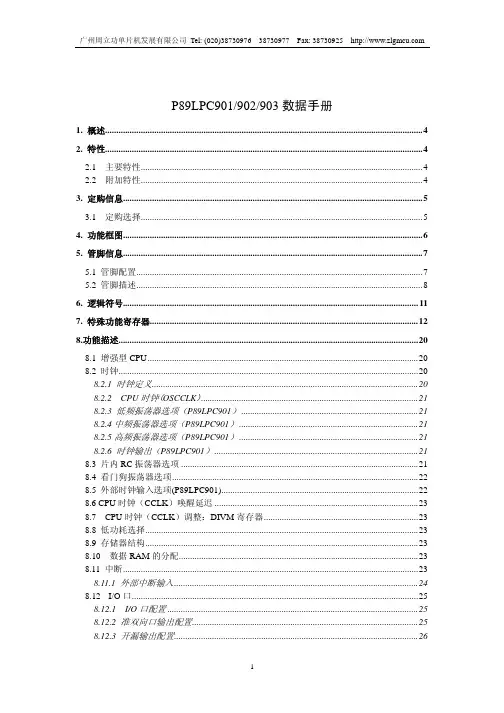
铷原子时钟源
是一种基于铷原子振荡器的高精度、高稳定度时钟源。
铷原子振荡器利用铷原子的固有频率进行振荡,具有较高的精确性和稳定性,广泛应用于各种计时和频率控制系统中。
铷原子时钟源的工作原理如下:
1. 铷原子在特定的光学激发条件下,会跃迁到高能态。
2. 当铷原子从高能态跃迁回低能态时,会辐射出特定波长的光子。
3. 利用光电倍增管等光传感器检测到光子辐射,并将其转换为电信号。
4. 对电信号进行放大、滤波和整形处理,得到稳定的矩形波信号。
5. 将矩形波信号输入到分频器或倍频器,得到所需频率的时钟信号。
铷原子时钟源具有以下优点:
1. 高的精度:铷原子振荡器的频率稳定性较高,可以实现毫秒级别的精度。
2. 高的稳定性:铷原子振荡器不受外界环境因素(如温度、磁场、振动等)的影响,具有很高的稳定性。
3. 抗干扰能力强:相较于其他类型的时钟源,铷原子时钟源对电磁干扰和射频干扰具有较高的抗干扰能力。
4. 小型化、低功耗:随着技术的发展,铷原子时钟源逐渐实现
小型化和低功耗,便于集成和应用。
铷原子时钟源在通信、导航、科学研究、精密测量等领域具有广泛的应用前景。
例如,在通信系统中,它可以作为基准时钟用于频率同步和时间戳记录;在导航系统中,它可以为卫星导航信号提供高精度的时间参考;在科学研究中,它可以用于精密测量实验中的时间基准等。
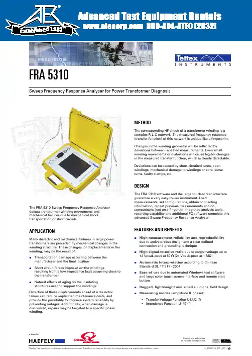
FRA 5310Sweep Frequency Response Analyser for Power Transformer DiagnosisThe FRA 5310 Sweep Frequency Response Analyser detects transformer winding movements and mechanical failures due to mechanical shock, transportation or short circuits.APPLICATIONMany dielectric and mechanical failures in large power transformers are preceded by mechanical changes in the winding structure. These changes, or displacements in the winding, may be the result of:⏹Transportation damage occurring between themanufacturer and the final location⏹Short circuit forces imposed on the windingsresulting from a low impedance fault occurring close to the transformer⏹Natural effects of aging on the insulatingstructures used to support the windingsDetection of these displacements ahead of a dielectric failure can reduce unplanned maintenance costs, and provide the possibility to improve system reliability by preventing outages. Additionally, when damage is discovered, repairs may be targeted to a specific phase winding. METHODThe corresponding HF circuit of a transformer winding is a complex R-L-C-network. The measured frequency response (transfer function) of this network is unique like a fingerprint. Changes in the winding geometry will be reflected by deviations between repeated measurements. Even small winding movements or distortions will cause legible changes in the measured transfer function, which is clearly detectable. Deviations can be caused by short-circuited turns, open windings, mechanical damage to windings or core, loose turns, faulty clamps, etc.DESIGNThe FRA 5310 software and the large touch-screen interface guarantee a very easy-to-use instrument. Load measurements, set configurations, obtain connecting information, repeat previous measurements and do comparisons just on a fingertip. Integrated analysis tools, reporting capability and additional PC software complete this advanced Sweep Frequency Response Analyser.FEATURES AND BENEFITS⏹High measurement reliability and reproducibilitydue to active probes design and a clear definedconnection and grounding technique⏹High signal-to-noise ratio due to output voltage up to12 Vpeak-peak at 50 Ω (24 Vpeak-peak at 1 MΩ)⏹Automatic Interpretation according to ChineseStandard DL / T 911 - 2004⏹Ease of use due to automated Windows test softwareand large color touch screen interface and remote startbutton⏹Rugged, lightweight and small all-in-one field design ⏹Measuring modes (amplitude & phase):▪Transfer Voltage Function U1/U2 (f)▪Impedance Function U1/I2 (f) 1981Previously stored curves are accessed using the History tab sheet, where information can be edited and updated at a later date.Automatic Test Setting (Sequence)Analysis page with limits set according to the standards A complete transformer test measurement list (sequence) can be predefined and executed automatically when required, making it simple to repeat a previous fingerprint measurement, even if the operator has no previous knowledge of the setup.ANALYSIS TOOLSThe analysis system allows multiple stored measurements to be loaded for detailed analysis, comparison, verification, reporting, etc.The measured transfer function curves can be displayed as Magnitude [dB], Phase [°], Impedance [ ] , Admittance [S] and Ratio.Additional comments can be stored with the single analysis displays so expert interpretation andassessments, further test instructions, etc can be included. Various display tools are easily accessible from the touch screen to allow simple analysis: Zoom-in and -out, auto scaling, linear and logarithmic scaling, curve shifting, measuring point labels, save as meta-file, printout, title editing, setup information editing, frequency band display,etc.Two frequency response curves and their difference.Cursors can easily be placed anywhere on the displayed curves giving the user information down to the last measuring point.Differences of curves with a definable limiter function can be calculated allowing parts of the curve to beweighted and highlighted to help the engineer's decision-making.Coherence between two or more curves can becalculated to give the engineer a powerful tool for the assessment and comparison of transformer transfercurves yielding valuable additional information.Transfer functions of 3 phases and their coherence.Interpretation according to Chinese Standard DL / T 911 - 2004 is supported. This interpretation is based on thecomparison of two curve, identifies slight, obvious and severe mechanical changes and differentiate between typical origins of the damage.Comparison of two transfer functions according to Chinese Standard DL / T 911- 2004.REPORT GENERATIONThe measured frequency response curves (raw data) are stored in a measuring data file together with all the related transformer nameplate data and other additional information. Reports can be created from the measured data file (raw data curves) or from any analysis data files previously created.The user can choose different report sizes from diagrams with short setup info to full reporting with all detailed setup and DUT information.Reports are automatically generated in XML- or HTML- format allowing the report file to be opened in a web browser or word processor.Data exportThe measuring files (raw data curves) are stored in XML format and can also be stored in CSV (comma-separated-values) format.They can be directly opened in Microsoft EXCEL or other spreadsheet programs where further customer specific data processing, calculation, comparison and documentation is possible.Any curve can also be stored as a picture for further use in customer specific documentation or reporting.SCOPE OF SUPPLYType 5310 Instrument in rugged shell case,Cable back pack including:▪ 2 Active Probes with 15 m double shielded cables,▪ 2 Ground Tapes 10 m,▪ 2 Ground Tape Clamps,▪User Manual, Test Certificate,▪Mains cable CD with external PC Analysis Software TECHNICAL DATAMeasurementType ActiveprobesFrequency Range 10 Hz .. 10 MHz, user definedVoltage Output max. 12 Vpeak-peak at 50 Ω,max. 24 Vpeak-peak at 1 MΩ, userdefinedInput Impedance selectable 50 Ω or 1 MΩOutput Impedance 50 ΩAccuracy ± 0.1 dB , zero calibratedFeasible accuracy: ± 0.5 dB down to -90dBDynamic range >100 dBMeasuring Points max. 2’000, user defined,logarithmicallyspaced, Protection Against short circuit, overloadData DisplayScaling Logarithmic or Linear, user defined Frequency Range 10 Hz .. 10 MHz, user definedPlot, Frequency vs. Magnitude, Impedance, Phase,Admittance, RatioControllerProcessor Celeron M, 1 GHzRAM 256MBInterfaces USB 2.0 , RS232Data Storage 40 GB Hard DiskDisplay 10.4", SVGA, Color TFTUser Interface built-in Touch ScreenGeneralOperatingTemperature0 .. +50°CStorageTemperature-20 .. +70°CRelative Humidity 10 .. 90 % non-condensingWeight Instrument 8 kg (17 lbs)DimensionsInstrument41 x 31 x 17 cm (16” x 12.2” x 7”)Remote Start Remote start button and indicator inprobeMains Universal, 90 .. 265 VAC,50 / 60 Hz, 75 VAInstrument OS Windows XP embeddedExternal PCSoftwareWindows 98 / 2000 / XPOrder code FRA 5310 No. 3490047Europe, Asia, South & Central America, Australia Haefely Test AG Birsstrasse 3004052 BaselSwitzerland☎ + 41 61 373 4111+ 41 61 373 4912****************China (Sales & Service Office)Haefely Test AG – Beijing Office8-1-602, Fortune StreetNo. 67, Chaoyang Road, Chaoyang DistrictBeijing, 100025P. R. China☎ + 86 10 8578 8099+ 86 10 8578 9908*****************.cnNorth AmericaHipotronics Inc.1650 Route 22PO Box 414Brewster, NY 10509USA☎ + 1 845 279 3644+ 1 845 279 2467*********************。
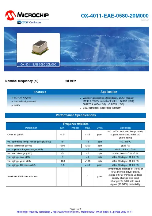
OX-4011-EAE-0580-20M000OCXONominal frequency (f0)20MHzFeaturesApplication•SC Cut Crystal •hermetically sealed •SMD•Wander generation (Standard /ZLAN Group)MTIE &TDEV compliant with:-G.812(zO1)-G.8273.4(zO4;zO5)-G.8263(zO6);•S3E compliant according GR1244Performance Specificationsall units in mmTP: max 260°C (@ solder joint, customer board level)T p: max: 10…30 secAdditional Information:This SMD oscillator has been designed for pick and place reflow solderingSMD oscillators must be on the top side of the PCB during the reflow process.Notes:Unless otherwise stated all values are valid after warm-up time and refer to typical conditions for supply voltage, frequency control voltage,load,temperature(25◦C).Subject to technical modification.USA:Europe:100Watts Street LandstrasseMt Holly Springs,P A1706574924NeckarbischofsheimGermanyTel:1.717.486.3411T el:+49(0)7268.801.0Fax:1.717.486.5920Fax:+49(0)7268.801.281Information contained in this publication regarding device applications and the like is provided only foryour convenience and may be superseded by updates.It is your reasonability to ensure that yourapplication meets with your specifications.MICROCHIP MAKES NO REPRESENT A TION ORWARRANTIES OF ANY KIND WHETHER EXPRESS OR IMPLIED,WRITTEN OR ORAL,ST ATUTORYOR OTHERWISE,RELA TED TO THE INFORMA TION INCLUDING,BUT NOT LIMITED TO ITSCONDITION,QUALITY,PERFORMANCE,MERCHANT ABILITY OR FITNESS FOR PURPOSE.Microchip disclaims all liability arising from this information and its e of Microchip devices in lifesupport and/or safety applications is entirely at the buyer’s risk,and the buyer agrees to defend,indemnify and hold harmless Microchip from any and all damages,claims,suits,or expenses resultingfrom such use.No licenses are conveyed,implicitly,or otherwise,under any Microchip intellectualproperty rights unless otherwise statedTrademarksThe Microchip and Vectron names and logos are registered trademarks of Microchip TechnologyIncorporated in the U.S.A.and other countries.List of appendicesAppendix_OX-4011-EAE-0580-20M000_Jitter II Appendix_OX-4011-EAE-0580-20M000_OX-401-9016-III 20M000_OX-4011-EAE-0580-10M000_MTIE_TDEVAppendix_OX-221-OX-40x_Power_on_time XIAppendix handling&processing note XIIThe following MTIE TDEV plots were generated from data collected on production devices over the course of a year and represent typical performance. Frequency is measured every second and converted to phase using Microchip’s golden standard TimeMonitor soft ware. Filtering is applied to the data per standards requirements, and limits where applicable, are shown in red. Additional information on standards and oscillatorrecommendations can be found in ZLAN-830 and ZLAN-3467 (formerly ZLAN-442 and ZLAN-68).Const. Temp ±1°K; slope 0,1°C/min, range 21..23°C Const. Temp ±5°F; slope 0,1°C/min,range 19.22..24.78°C Trapezoid_Pattern_slope 0,5°C/min,range +2,5...42,5°C Triangle-Pattern_slope 0,2°C/min,range -40...85°CConst. Temp ±1°K; slope 0,1°C/min, range 21..23°C Const. Temp ±5°F; slope 0,1°C/min,range 19.22..24.78°C Trapezoid_Pattern_slope 0,5°C/min,range +2,5...42,5°C Triangle-Pattern_slope 0,2°C/min,range -40...85°CConst. Temp ±1°K; slope 0,1°C/min, range 21..23°C Const. Temp ±5°F; slope 0,1°C/min,range 19.22..24.78°C Trapezoid_Pattern_slope 0,5°C/min,range +2,5...42,5°C Triangle-Pattern_slope 0,2°C/min,range -40...85°CConst. Temp ±1°K; slope 0,1°C/min, range 21..23°C Const. Temp ±5°F; slope 0,1°C/min,range 19.22..24.78°C Trapezoid_Pattern_slope 0,5°C/min,range +2,5...42,5°C Triangle-Pattern_slope 0,2°C/min,range -40...85°CConst. Temp ±1°K; slope 0,1, range 21..23°C Const. Temp ±5°F; slope 0,1,range 19.22..24.78°C Trapezoid_Pattern_slope 0,5,range +2,5...42,5°C Triangle-Pattern_slope 0,2,range -40...85°CConst. Temp ±1°K; slope 0,1, range 21..23°C Const. Temp ±5°F; slope 0,1,range 19.22..24.78°C Trapezoid_Pattern_slope 0,5,range +2,5...42,5°C Triangle-Pattern_slope 0,2,range -40...85°CConst. Temp ±1°K; slope 0,1, range 21..23°C Const. Temp ±5°F; slope 0,1,range 19.22..24.78°C Trapezoid_Pattern_slope 0,5,range +2,5...42,5°C Triangle-Pattern_slope 0,2,range -40...85°CConst. Temp ±1°K; slope 0,1, range 21..23°C Const. Temp ±5°F; slope 0,1,range 19.22..24.78°C Trapezoid_Pattern_slope 0,5,range +2,5...42,5°C Triangle-Pattern_slope 0,2,range -40...85°CApplicationUnless otherwise noted, the products listed in the catalogue are designed for use with ordinary electrical devices, such as stationary and portable communication, control, measurement equipment etc.. They are designed and manufactured to meet a high degree of reliability (lifetime more than 15 years) under normal …commercial“ application conditions. Products dedicated for automotive and H-Rel applications are specifically identified for these applications. If you intend to use these …commercial“ products for airborne, space or critical transport applications, nuclear power control, medical devices with a direct impact on human life, or other applications which require an exceptionally high degree of reliability or safety, please contact the manufacturer.Electrostatic SensitivityCrystal oscillators are electrostatic sensitive devices. Proper handling according to the established ESD handling rules as in IEC 61340-5-1 and EN 100015-1 is mandatory to avoid degradations of the oscillator performance due to damages of the internal circuitry by electrostatics. If not otherwise stated, our oscillators meet the requirements of the Human Body Model (HBM) according to JESD22-A114F.HandlingExcessive mechanical shocks during handling as well as manual and automatic assembly have to be avoided. If the oscillator was unintentionally dropped or otherwise subject to strong shocks, please verify that the electrical function is still within specification.Improper handling may also detoriate the coplanarity of bended leads of SMD components. SolderingOscillators can be processed using conventional soldering processes such as wave soldering, convection, infrared, and vapour phase reflow soldering under normal conditions. Solderability is guaranteed for one year storage under normal climatic conditions (+5°C to +35°C @ 40% to 75% relative humidity), however typically sufficient solderability –depending on the process – is maintained also for longer time periods. In cases of doubt, components older than one year should undergo a sample solderability test.The recommended reflow solder profile for SMT componets is according IPC/JEDEC J-STD-020 (latest revision)SMD oscillators must be on the top side of the PCB during the reflow process.After reflow soldering the frequency of the products may have shifted several ppm, which relaxes after several hours or days, depending on the products. For details please contact the manufacturer.CleaningCleaning is only allowed for hermetically sealed oscillators. Devices with non hermetical enclosures (e.g. with trimmer holes) shall not be cleaned by soaking or in vapour, because residues from the cleaning process may penetrate into the interior, and degrade the performance.Our products are laser marked. The marking of our oscillators is resistant to usual solvents, such as given in IEC 60068-2-45 Test XA. For applicable test conditions see IEC 60679-1.Ultrasonic cleaning is usually not harmful to oscillators at ultrasonic frequencies of 20kHz at the sound intensities conventional in industry. Sensitive devices may suffer mechanical damage if subjected to 40kHz ultrasound at high sound pressure. In cases of doubt, please conduct tests under practical conditions with the oscillators mounted on the PC board.Hermetical SealIf the device is specified as hermetically sealed, it meets the requirements of IEC 60679-1, i.e. for enclosures with a volume smaller than 4000mm³ the leak rate is below 5*10-8 bar cm3/s, for larger enclosures it is below 1*10-6 bar c bar cm3/s, tested according to IEC 60068-2-17 Test Qk.Glass feed-throughs may be damaged as a result of mechanical overload, such as bending the connection leads or cutting them with an unappropriated tool. In order to avoid microcracking, the wire must be held fixed in position by a pressure pad between glass feed-through and the bending point during the bending process. Check: there should be no damaged edges on the glass feed-through after the bending.Tape & ReelThe packing in tape and reel is according to IEC 60286-3.Details see tape & reel data sheets.QualificationVectron products are undergoing regular qualification/reliability tests as per product family definition. Results are available upon request. Customer specific qualification tests are subject to agreement.If not otherwise stated, the product qualifications are performed according to IEC 60679-5 or other valid industry standards.ScreeningOur oscillators are 100% tested, and all key manufacturing processes are controlled by Statistical Process Control (SPC). Additional screening is therefore usually not required.On request, we can perform screening tests according to MIL-PRF-55310, class B for discrete or hybrid constructions of commercial (COTS) products. For special requirements see the High Reliability Clock section.Demounting/Desoldering of Ocsillator device for analysis:The removal or desoldering of oscillators from customer application after SMT process may cause damage to the device if not handeld appropriately. It may lead to parametric change such as frequency shift (like OCXO: up to +/- 200 ppb) . It is utmost important to minimize the direct heat exposure to the device in order to avoid such effects. Use of hot air gun for desoldering should be avoided.A mechanical stress could also destroy the part, if exposed to excessive mechanical shock after removal process. Appropriate shock protection & ESD designated packaging must be used to avoid any external mechanical shock for FA return process.In general, the products* withstand the tests listed in the following Table 1, which are based on valid industry standards.*Additional note: Test conditions could vary for different product families and individual product specifications depending on the customer as well as product requirements.Recommended Environmental Test ConditionsTable 1。
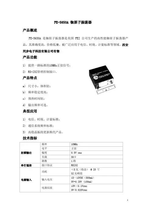
FE-5650A 铷原子振荡器产品概述FE-5650A是铷原子振荡器是美国 FEI 公司生产的高性能铷原子振荡器产品,其准确度高,价格低廉,被广泛应用于电信、时统、计量标准等领域。
西安同步电子科技有限公司有售产品功能1)提供一路标准的10MHz正弦信号;2)RS-232管理控制接口。
产品特点a)尺寸小,体积轻;b)频率稳定度高;c)预热时间短;d)输出频率可选。
典型应用1)电信、时统、计量标准;2)通信系统频率标准;3)高稳晶振的更新换代产品。
技术指标射频输出频率10MHz电平正弦幅度0.5V rms 负载50Ω路数1路串行通信接口协议RS232电源输入功耗<8瓦(稳态) @ 25 ℃32瓦峰值输入电压15~18VDC(500mA)5V+0.25V (100mA)电源纹波15V:<0.1Vrms5V<0.020Vrms物理尺寸尺寸37×77×76mm 重量<338g MTBF >10万小时电气特性工作温度-5℃~+50℃频率变化(全温度范围)±3E- 10(-5℃~+50℃)频率变化(全电压范围)<2E- 11性能参数短稳≤1.4E-11/1s≤4.4E-12/10s≤1.4E-12/100s相噪≤-100dBc/Hz(10Hz)≤-125dBc/Hz(100Hz)≤-145dBc/Hz(1KHz) 谐波≤-30dBc杂波≤-60dBc准确度(出厂设置)±5E-11重现性±5E-11老化率2E- 9 /年2E- 11 /天数字调节频率范围2E- 7最小步进 1.74E- 14模拟调节范围2E- 7(“C”电位器)2E- 9(0到 5V电压)最小步进1E-11输入电压0 ~5V预热时间4分钟安装尺寸:。

通信电子线路重点总结第一章1、一个完整的通信系统应包括信息源、发送设备、信道、接收设备和收信装置五部分。
2、只有当天线的尺寸大到可以与信号波长相比拟时,天线才具有较高的辐射效率。
这也是为什么把低频的调制信号调制到较高的载频上的原因之一。
3、调制使幅度变化的称调幅,是频率变化的称调频,使相位变化的称调相。
4、解调就是在接收信号的一方,从收到的已调信号中把调制信号恢复出来。
调幅波的解调称检波,调频波的解调叫鉴频。
第二章1、小信号调谐放大器是一种最常见的选频放大器,即有选择地对某一频率的信号进行放大的放大器。
它是构成无线电通信设备的主要电路,其作用是放大信道中的高频小信号。
所谓调谐,主要是指放大器的集电极负载为调谐回路。
2、调谐放大器主要由放大器和调谐回路两部分组成。
因此,调谐放大器不仅有放大作用,还有选频作用。
其选频性能通常用通频带和选择性两个指标衡量。
3、并联谐振回路01LC0L10CLCCLCL(C称为谐振回路的特性阻抗)并联谐振回路的品质因数是由回路谐振电阻与特性阻抗的比值定义的,即QR0LCR00LR00CR0回路的越大,Q值越大,阻抗特性曲线越尖锐;反之,00R0越小,Q值越小,阻抗特性曲线越平坦。
在谐振点处,电压幅值最大,当0时,回路呈现感性,电压超前电流一个相角,电压幅值减小。
当相角,电压幅值也减小。
4、谐振回路的谐振曲线分析UUm11(Q2f2)f0时,回路呈现容性,电压滞后电流一个U对于同样频偏f,Q越大,Um值越小,谐振曲线越尖锐一个无线电信号占有一定的频带宽度,无线电信号通过谐振回路不失真的条件是谐振回路的幅频特性是一常数,相频特性正比于角频率。
在无线电技术中,常把Um从1下降到U1ff2(以dB表示,从0下降到-3dB)处的两个频率1和22f0.7的范围叫做通频带,以符号B或Bf2f1f0Q表示。
即回路的通频带为选择性是谐振回路的另一个重要指标,它表示回路对通频带以外干扰信号的抑制能力。
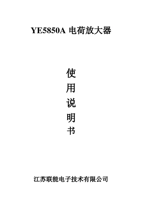
YE5850A电荷放大器使用说明书江苏联能电子技术有限公司一、概述YE5850A电荷放大器是一种输出电压与输入电荷量成正比的宽带电荷放大器,可配接压电式传感器测量振动、冲击、压力等机械量,广泛应用于水利、动力、采矿、交通、建筑、地震、航空、航天、兵器、化爆等部门。
由于下限频率极低,因而特别适合对压电式压力,力传感器进行准静态标定。
YE5850A电荷放大器具有如下特点:●采用高质量进口器件,稳定可靠●可输入电荷信号或电压信号●输入等效直流电阻可达1014Ω●频带宽2μH z-100KH z●输入可配接长电缆而不影响测量精度●操作简单,维修方便,性能好,价格低●有两种极性输出使用环境符合SJ2075-82《电子测量仪器环境要求及其试验方法》Ⅱ组条件。
二、技术参数2.1 输入特性2.1.1 最大输入电荷量:106PC。
2.1.2 直流分流电阻:约1014Ω。
2.3 传感器灵敏度调节:三位数字转盘调节传感器电荷灵敏度1~109.9PC/ Unit(1)。
2.4 准确度三档低灵敏度档:当输入负载分别小100nF、47nF、10nF时,1KHz基准条件(2),(2) <±1%,额定工作条件(3) <±2%。
二档高灵敏度档:当输入负载分别小4.7nF时,1KHz基准条件<±1%,额定工作条件<±2%。
2.5滤波器及频率响应2.5.1 高通滤波器:下限频率(-3dB)和时间常数见表1。
注:(1)unit表示机械单位,取决于所用传感器的单位,例:加速度g,绝对加速度单位m/S2,压力单位Kg/cm2,力单位N等。
(2)基准条件:a、20℃±2%;b、相对湿度(45~75)%RH;c、供电电压AC220V±2%,DC±18V~27V;d、输出负载>10KΩ。
(3)额定工作条件:a、0℃~40℃;b、相对湿度(20~90)%RH;c、供电电压AC220V±10%,DC±18V~27V。
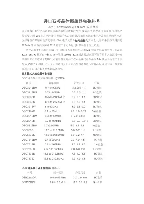
进口石英晶体振荡器完整料号本文由 编辑整理电子技术日益发达具奇美电内部透露明年所有产品线,包括电视,监视器,平板电脑,手机等产品都要达到20%市占率的目标,智能手机大量出货,可能而知现在电子产品在市场的地位,而支撑这些产品顺利出货的幕后CEO电子元器件贴片晶振是其中之一,每部手机必须用到的32.768K晶体,石英振荡器3225就这二个元件也足以带动整个行业销量.各个品牌手机结构不同设计的电路板也有大同小异,CDMA智能手机必须用到石英晶体3225 26MHZ蓝牙也一样,ATM一般用12MHZ 3225振荡器,振荡器可能有很多人会混淆一连串的字母不知道哪个是哪个,可能有些采购商工程跟他说找有源晶振DSV就给了他这三个字母,而采购又是刚刚上任不久不知道这是什么东西只知道带电压有源晶振,这里列举一些比较常用的进口日产石英晶体振荡器料号.日本株式大真空晶体振荡器DSO开头属于普通振荡器料号(SPXO)料号频率范围产品尺寸封装DSO321SBM 0.7 to 90MHz 3.2×2.5×1.1 3K/盘装DSO321SBN 0.7 to 90MHz 3.2×2.5×1.1 3K/盘装DSO323SD 13.5 to 212.5MHz 3.2×2.5×1.1 3K/盘装DSO323SK 13.5 to 212.5MHz 3.2×2.5×1.1 3K/盘装DSO321SW 3 to 60MHz 3.2×2.5×0.9 3K/盘装DSO211AR 0.4 to 80MHz 2.0×1.6×0.72 3K/盘装DSO221SBM 3.25 to 52MHz 5×2.0×0.815 3K/盘装DSO221SR 0.2 to 167MHz 2.5×2.0×0.815 3K/盘装DSO531SBM 0.7 to 90MHz 5.0×3.2×1.1 1K/盘装DSO533SJ 13.5 to 212.5MHz 5.0×3.2×1.1 1K/盘装DSO533SK 13.5 to 212.5MHz 5.0×3.2×1.1 1K/盘装DSO751SBM 0.7 to 90MHz 7.3×4.9×1.5 1K/盘装DSO751SR 0.2 to 167MHz 7.3×4.9×1.5 1K/盘装DSO753HK 212.5 to 350MHz 7.0×5.0×2.0 1K/盘装DSO753SD 13.5 to 212.5MHz 7.3×4.9×1.5 1K/盘装DSO753SJ 13.5 to 212.5MHz 7.3×4.9×1.5 1K/盘装DSB开头属于温补振荡器(TCXO)料号频率范围产品尺寸封装DSB321SDA 9.6 to 52 MHz 3.2×2.5×0.9 3K/盘装DSB321SCL 9.6 to 52 MHz 3.2×2.5×0.9 3K/盘装DSB211SCL 13 to 52 MHz 2.1×1.7×0.63 3K/盘装DSB211SDB 13 to 52 MHz 2.1×1.7×0.63 3K/盘装DSB221SCL 9.6 to 52 MHz 2.5×2.0×0.8 3K/盘装DSB221SDA 9.6 to 52 MHz 2.5×2.0×0.8 3K/盘装DSB535SD 9.6 to 40 MHz 5.0×3.2×1.05 1K/盘装DSB535SC 10 to 30MHz 5.0×3.2×1.35 1K/盘装DSB535SG 10 to 40 MHz 5.0×3.2×1.35 1K/盘装DSV开头属于压控振荡器(VCXO)料号频率范围产品尺寸封装DSV531SB 5 to 50MHz 5.0×3.2×1.2 1K/盘装DSV531SV 1.25 to 80MHz 5.0×3.2×1.2 1K/盘装DSV532SV 1.25 to 80MHz 5.0×3.2×1.1 1K/盘装DSV753SB 4 to 50MHz 7.0×5.0×2.0 1K/盘装DSV753SK 40 to 170MHz 7.3×4.9×1.5 1K/盘装DSV753SD 80 to 170MHz 7.3×4.9×1.5 1K/盘装DSV321SR 6.75 to 90MHz 3.2×2.5×1.1 3K/盘装DSV323SJ 80 to 170MHz 3.2×2.5×1.1 3K/盘装DSV323SK 40 to 170MHz 3.2×2.5×1.1 3K/盘装DSV221SR 7.5 to 60MHz 2.5×2.0×0.815 3K/盘装DSV221SV 6.75 to 90MHz 2.5×2.0×0.815 3K/盘装DSV211AV 12 to 80MHz 2.0×1.6×0.72 3K/盘装DSA开头属于压控温补振荡器(VC-TCXO)料号频率范围产品尺寸封装DSA211SCL 13 to 52 MHz 2.1×1.7×0.63 3K/盘装DSA221SDA 9.6 to 52 MHz 2.5×2.0×0.8 3K/盘装DSA221SJ 10 to 40 MHz 2.5×2.0×0.8 3K/盘装DSA221SCL 9.6 to 52 MHz 2.5×2.0×0.8 3K/盘装DSA321SDA 9.6 to 52 MHz 3.2×2.5×0.9 3K/盘装DSA321SCL 9.6 to 52 MHz 3.2×2.5×0.9 3K/盘装DSA535SG 10 to 40 MHz 5.0×3.2×1.35 1K/盘装DSA535SC 10 to 30MHz 5.0×3.2×1.35 1K/盘装DSA535SD 9.6 to 40 MHz 5.0×3.2×1.05 1K/盘装日产爱普生振荡器系列TCO开头温补振荡器料号频率范围产品尺寸封装TCO-7087 1.5 to 160.00MHZ 7.0×5.0×1.6 1K/盘装TCO-710X 1.5 to 75MHZ 5.0×3.2×1.0 1K/盘装SG-310 2.0 to 80.0MHZ 3.2×2.5×1.05 3K/盘装TG-5035CE 10.0 to 40.0MHZ 3.2×2.5×0.9 3K/盘装VG开头压控振荡器料号频率范围产品尺寸封装VG-4232CA 60 to 80.0MHZ 7.0×5.0×1.4 1K/盘装VG-4231CB 1.0 to 80.0MHZ 5.0×3.2×1.2 1K/盘装VG-4231CA 1.0 to 60.0MHZ 7.0×5.0×1.4 1K/盘装日产西铁城振荡器系列CSX开头压控振荡器料号频率范围产品尺寸封装CSX532T 12.8 to 26.0MHZ 3.2×2.5×1.0 1K/盘装CSX-750V 2.0 to 4.0MHZ 7.0×5.0×1.6 1K/盘装CSX750F 1.0 to 80.0MHZ 7.0×5.0×1.6 1K/盘装CSX325T 1.0 to 38.0MHZ 3.2×2.5×1.0 3K/盘装CSX325P 1.0 to 125.0MHZ 3.2×2.5×1.0 3K/盘装CSX-252T 19.2 to 38.4MHZ 2.5×2.0×1.0 3K/盘装振荡器根据振荡形式不同又可分很多种,比如石英晶体振荡器,环形振荡器,石英晶体多谐振荡器,通过电容的充电和放电使两个暂稳态相互交替,不用触发来产生自激振荡输出周期性的矩形脉冲信号又含有丰富的谐波分量这种叫做多谐振荡器,多谐振荡器主要利用谐振原理实现的振荡器.而石英晶体振荡器则利用压电效应,在石英晶片受到外加交变电场的作用下产生机械振动,当交变电场的频率与石英晶体的固有频率相同时,振动变得更强烈这就是晶体谐振特性的反应.因此信号发生电路上要产生方波时主要的起振元件大多会采用晶体振荡器.。
丹东华奥电子有限公司简介LD209A(替代CS209A)是一种双极性集成电路,主要用于金属检测或是接近感应。
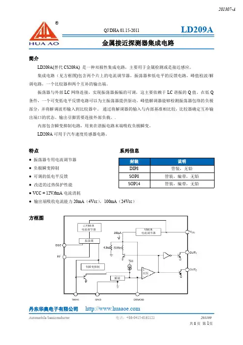
集成电路(见方框图)包含两个片上的电流调节器,振荡器和低电平的反馈电路,峰值检波/解调电路,一个比较器和两个互补的输出端。
振荡器与外部LC 网络连接,实现振荡器振幅的可调,这主要依赖于LC 谐振的Q 值。
在低Q 条件,一个可变低电平反馈电路可以为主振荡器提供驱动。
峰值解调器能够检测振荡器包络的负极部分,并将解调波形输入到比较器中。
通过将解调器的输入与内部基准相比较,比较器确定互补输出端口的状态。
输出引脚需要连接外部负载。
.内部包含瞬变抑制电路,用来在谐振电路末端吸收负极瞬变。
LD209A 可用于汽车速度传感器电路。
特点系列信息●振荡器专用电流调节器●负极瞬变抑制●可调的低电平反馈●改进的过热保护性能●VCC =12V ,6mA 电流消耗●输出端吸收电流能力20mA (4Vcc ),100mA (24Vcc )方框图封装说明DIP8管装,无铅SOP8管装,编带,无铅SOP14管装,编带,无铅金属接近探测器集成电路△VBE/R电流调节器VBE/R 电流调节器负瞬变抑制解调比较振荡器丹东华奥电子有限公司管脚描述绝对最大范围引脚缩写功能DIP8&SO8SO1411OSC 连接于OSC 和RF 的可变反馈电阻用于设置检查范围22TANK 连接并联谐振电路33GND 地44OUT1互补的集电极开路输出,当OUT1为低时,有金属存在56OUT2互补的集电极开路输出,当OUT1为高时,有金属存在610DEMOD 控制OUT1和OUT 2状态的比较器输入端712V CC 电源电压813RF 连接于OSC 和RF 的可变反馈电阻用于设置检查范围5,7,8,9,11,14NC空参数缩写数值单位电源电压24V 能量消耗(TA =125℃)200mW 储存温度-55to +165℃结温度-40to +150℃静电放电(除TANK 引脚)2kV焊接温度波峰焊(仅通孔形式)回流焊(仅贴片形式)10sec.最大,260℃峰值60sec.大于183℃,230℃峰值DIP8&SOP8SOP14丹东华奥电子有限公司电特性-40℃≤TA ≤125℃,除非另外说明典型工作特性出转换延时&输出负载输出转换延时&温度参数测试环境最小值典型值最大值单位电源电流I CC V CC =4VV CC =12V V CC =24V 3.56.011.0 6.011.620.0mA 谐振电流V CC =20V -550-300-100μA 解调器充电电流V CC =20V -60-30-10μA 输出漏电流V CC =24V 0.0110.0μA 输出端饱和电压V SA T V CC =4V ,I S =20mA V CC =24V ,I S =100mA60200200500mV 振荡器偏压V CC =20V 1.1 1.9 2.5V 反馈偏压V CC =20V 1.1 1.9 2.5V Osc-Rf 偏压V CC =20V -250100550mV 保护电压I TANK =-10mA-10.0-8.9-7.0V 检测门限72014401950mV 释放门限55012001700mV解调电压&距离(不同的RF)工作原理LD209A是一款金属探测电路。
OPA1013- 精密单电源双路运算放大器OPA1013CN8P 所有无铅库存$0.00OPA124- 低噪声的精密差动运算放大器OPA124U D 所有无铅库存$0.00OPA124UA D 所有无铅库存$0.00OPA129- 超低偏置电流差动运算放大器OPA129U D 所有无铅库存$0.00OPA129UB D 所有无铅库存$0.00OPA131- 通用 FET- 输入运算放大器OPA131UA D 所有无铅库存$0.00OPA1602- OPA1602、OPA1604 SoundPlus 高性能、双极输入音频运算放大器OPA1602AID D 暂时缺货$0.00OPA1642- Sound-Plus 高性能、JFET 输入音频运算放大器OPA1642AID D 暂时缺货$0.00OPA2130- 低功耗精密 FET 输入运算放大器OPA2130UA D 所有无铅库存$0.00OPA2137- 低成本 FET 输入运算放大器OPA2137P P 所有无铅库存$0.00OPA2141- 10MHz 单电源低噪声 JFET 精密放大器 ]]OPA2141AID D 所有无铅库存$0.00OPA2141AIDR D 所有无铅库存$0.00OPA2227- 高精度、低噪声运算放大器OPA2227P P 所有无铅库存$0.00OPA2227U D 所有无铅库存$0.00OPA2227UA D 所有无铅库存$0.00OPA2228- 高精度低噪声运算放大器OPA2228P P 所有无铅/绿色环保库存$0.00OPA2228PA P 所有无铅库存$0.00OPA2228U D 所有无铅库存$0.00OPA2228UA D 所有无铅库存$0.00OPA2333-HT- 1.8V 微功耗 CMOS 运算放大器OPA2333SJD JD 所有无铅无偏好** 库存$0.00OPA2334- 最大漂移0.05uV/℃ 的单电源 CMOS 运算放大器OPA2334AIDGST DGS 所有无铅/绿色环保库存$0.00 OPA2335- 最大漂移0.05uV/℃ 的单电源 CMOS 运算放大器OPA2335AIDGKT DGK 所有无铅库存$0.00 OPA2335AIDR D 所有无铅/绿色环保库存$0.00 OPA2338- MicroSIZE、单电源 CMOS 运算放大器微放大器系列OPA2338EA/250DCN 所有无铅/绿色环保库存$0.00OPA2354- 250MHz 轨至轨 I/O CMOS 双路运算放大器OPA2354AIDDA DDA 所有无铅库存$0.00 OPA2354AIDGKT DGK 所有无铅库存$0.00 OPA2376- 精密、低噪声、低静态电流运算放大器OPA2376AIDR D 所有无铅/绿色环保库存$0.00 OPA2376AIYZDT YZD 所有无铅/绿色环保库存$0.00 OPA2380- 高速精确互阻抗放大器OPA2380AIDGKT DGK 所有无铅/绿色环保库存$0.00 OPA2652- SpeedPlus(TM) 双路 700MHz 电压反馈运算放大器OPA2652U D 所有无铅/绿色环保库存$0.00 OPA2684- 双路低功耗电流反馈运算放大器OPA2684ID D 暂时缺$0.00货OPA2690- 具有禁用功能的双路宽带电压反馈运算放大器OPA2690ID D 所有无铅/绿色环保库存$0.00 OPA2703- 12V CMOS 轨至轨 I/O 运算放大器OPA2703UA D 所有无铅/绿色环保库存$0.00 OPA2703UAG4 D 所有无铅库存$0.00 OPA2704- 12V CMOS 轨至轨 I/O 运算放大器OPA2704EA/250DGK 所有无铅库存$0.00 OPA2704EA/250G4 DGK 所有无铅库存$0.00 OPA2704PA P 所有无铅/绿色环保库存$0.00 OPA2890- 具有禁用功能的双路低功耗宽带电压反馈运算放大器OPA2890ID D 所有无铅/绿色环保库存$0.00 OPA320- 20MHz、0.9pA Ib、RRIO、精密 CMOS 运算放大器OPA320AIDBVT DBV 所有无铅库存$0.00 OPA320SAIDBVT DBV 暂时缺$0.00货OPA3355- 具有关断状态的 2.5V 200MHz 的 GBW CMOS 三路运算放大器OPA3355EA/250PW 所有无铅/绿色环保库存$0.00 OPA3355UA D 所有无铅库存$0.00 OPA337- MicroAmplifier(TM) 系列微型单电源 CMOS 运算放大器OPA337NA/250DBV 所有无铅/绿色环保库存$0.00 OPA343- MicroAmplifier(TM) 系列单电源轨至轨运算放大器OPA343UA D 所有无铅/绿色环保库存$0.00 OPA347- 微功耗轨至轨运算放大器OPA347NA/250DBV 所有无铅/绿色环保库存$0.00 OPA347PA P 所有无铅/绿色环保暂时缺$0.00货OPA347SA/250DCK 所有无铅库存$0.00 OPA353- MicroAmplifier(TM) 系列高速单电源轨至轨运算放大器OPA353UA D 所有无铅/绿色环保库存$0.00 OPA364- 1.8V、高 CMR、RRIO 运算放大器OPA364AID D 所有无铅/绿色环保库存$0.00 OPA364AIDBVT DBV 所有无铅/绿色环保库存$0.00 OPA364IDBVT DBV 所有无铅/绿色环保库存$0.00 OPA3692- 具有禁用功能的三路宽带固定增益缓冲器OPA3692ID D 所有无铅/绿色环保库存$0.00 OPA3692IDBQT DBQ 所有无铅/绿色环保库存$0.00 OPA379- 1.8V、2.9µA、90kHz、轨至轨 I/O 运算放大器OPA379AIDCKT DCK 所有无铅/绿色环保库存$0.00 OPA380- 高速精密互阻抗放大器OPA380AIDGKT DGK 所有无铅库存$0.00 OPA4134- SoundPlus(TM) 高性能音频运算放大器OPA4134UA D 所有无铅库存$0.00 OPA4170- 36V、微功耗、轨至轨输出、四路、通用运算放大器OPA4170AID D 所有无铅库存$0.00 OPA4170AIPW PW 所有无铅库存$0.00 OPA4350- MicroAmplifier(TM) 系列高速单电源轨至轨运算放大器OPA4350EA/250DBQ 所有无铅/绿色环保库存$0.00 OPA4350UA D 所有无铅/绿色环保库存$0.00 OPA4353- MicroAmplifier(TM) 系列高速单电源轨至轨运算放大器OPA4353UA D 所有无铅/绿色环保库存$0.00 OPA4364- 1.8V、高 CMR、RRIO 运算放大器OPA4364AID D 所有无铅/绿色环保库存$0.00 OPA4704- 12V CMOS 轨至轨 I/O 运算放大器OPA4704UA D 所有无铅库存$0.00 OPA548- 高电压大电流运算放大器,出色的输出摆幅OPA548FKTWT KTW 所有无铅/绿色环保库存$0.00 OPA548T KVT 所有无铅/绿色环保库存$0.00 OPA561- 大电流运算放大器OPA561PWP PWP 所有无铅/绿色环保库存$0.00 OPA606- Wide-Bandwidth Difet(R) 运算放大器OPA606KP P 所有无铅/绿色环保库存$0.00 OPA656- 宽带单位增益稳定 FET 输入运算放大器OPA656N/250DBV 所有无铅库存$0.00 OPA656N/250G4DBV 所有无铅库存$0.00 OPA656NB/250DBV 所有无铅库存$0.00 OPA656U D 所有无铅库存$0.00 OPA656UB D 所有无铅库存$0.00 OPA694- 宽带、低功耗、电流反馈放大器OPA694ID D 所有无铅库存$0.00OPA1013- 精密单电源双路运算放大器OPA1013CN8P 所有无铅库存$0.00 OPA121- 低成本的精密差动运算放大器OPA121KU D 所有无铅库存$0.00 OPA124- 低噪声的精密差动运算放大器OPA124U D 所有无铅库存$0.00 OPA124UA D 所有无铅库存$0.00 OPA129- 超低偏置电流差动运算放大器OPA129U D 所有无铅库存$0.00 OPA129UB D 所有无铅库存$0.00 OPA130- 低功耗精密 FET 输入运算放大器OPA130UA D 所有无铅库存$0.00 OPA131- 通用 FET- 输入运算放大器OPA131UA D 所有无铅库存$0.00 OPA132- 高速 FET 输入运算放大器OPA132U D 所有无铅库存$0.00 OPA132UA D 所有无铅库存$0.00 OPA134- SoundPlus(TM) 高性能音频运算放大器OPA134PA P 所有无铅/绿色环保库存$0.00OPA134UA D 所有无铅无偏好** 库存$0.00OPA137- 低成本 FET 输入运算放大器OPA137P P 所有无铅无偏好** 库存$0.00OPA137PA P 库存$0.00 OPA140- 11MHz 单电源、低噪声、精密轨至轨输出 JFET 放大器OPA140AID D 所有无铅库存$0.00 OPA140AIDBVT DBV 所有无铅库存$0.00 OPA140AIDGKT DGK 所有无铅库存$0.00 OPA141- 10MHz 单电源低噪声 JFET 精密放大器OPA141AID D 所有无铅无偏好** 库存$0.00OPA141AIDGKT DGK 所有无铅库存$0.00OPA1602- OPA1602、OPA1604 SoundPlus 高性能、双极输入音频运算放大器OPA1602AID D 暂时缺货$0.00OPA1611- 1.1nV/√Hz 噪声、低功耗精密运算放大器OPA1611AID D 所有无铅库存$0.00OPA1612- 1.1nV/√Hz 噪声、低功耗精密运算放大器OPA1612AID D 所有无铅库存$0.00OPA1632- 全差动 I/O 音频放大器OPA1632D D 所有无铅/绿色环保库存$0.00OPA1632DR D 所有无铅库存$0.00OPA1641- Sound-Plus 高性能、JFET 输入音频运算放大器OPA1641AID D 所有无铅库存$0.00OPA1642- Sound-Plus 高性能、JFET 输入音频运算放大器OPA1642AID D 暂时缺货$0.00OPA1644- OPA1641/1642/1644 SoundPLUS™ 高性能 JFET 输入音频运算放大器OPA1644AID D 所有无铅无偏好** 库存$0.00OPA1654- Sound Plus 低噪声和低失真通用 FET 输入音频运算放大器OPA1654AID D 所有无铅库存$0.00OPA1654AIPW PW 所有无铅库存$0.00OPA1662-Q1- 汽车类 Sound Plus、低功耗、低噪声和低失真音频运算放大器OPA1662AIDGKRQ1 DGK 所有无铅库存$0.00OPA1662AIDRQ1 D 库存$0.00OPA1664- Sound Plus 低功耗、低噪声和低失真音频运算放大器OPA1664AID D 所有无铅库存$0.00OPA1664AIPW PW 所有无铅无偏好** 库存$0.00OPA170- 采用微型封装的 36V、微功耗、轨至轨输出、通用运算放大器OPA170AID D 所有无铅库存$0.00OPA170AIDBVT DBV 所有无铅库存$0.00OPA170AIDRLR DRL 所有无铅库存$0.00OPA170AIDRLT DRL 所有无铅库存$0.00OPA171- 采用微型封装的 36V 通用低功耗 RRO 运算放大器OPA171AID D 所有无铅库存$0.00OPA171AIDBVT DBV 所有无铅库存$0.00OPA171AIDRLT DRL 所有无铅库存$0.00OPA177- 精密运算放大器OPA177FP P 库存$0.00OPA177GP P 所有无铅库存$0.00OPA177GS D 所有无铅库存$0.00OPA177GS/2K5 D 所有无铅库存$0.00OPA188- 0.03μV/°C、6μV Vos、低噪声、轨至轨输出、36V 零漂移运算放大器OPA188AIDGKT DGK 所有无铅库存$0.00OPA1S2385- 具有集成开关和缓冲器的 200-MHz CMOS 跨阻放大器 (TIA)OPA1S2385IDRCT DRC 暂时缺货$0.00OPA211- 1.1nV/(sqrt)Hz Noise, Low Power, Precision Operational Amplifier in DFN-8 Pkg OPA211AIDR D 所有无铅/绿色环保库存$0.00OPA211ID D 所有无铅/绿色环保库存$0.00OPA211IDRGT DRG 所有无铅/绿色环保库存$0.00 OPA2130- 低功耗精密 FET 输入运算放大器OPA2130UA D 所有无铅库存$0.00 OPA2131- 通用 FET 输入运算放大器OPA2131UA D 所有无铅无偏好** 库存$0.00OPA2131UJ D 所有无铅库存$0.00 OPA2132- 高速 FET 输入运算放大器OPA2132P P 库存$0.00OPA2132PA P 所有无铅无偏好** 库存$0.00OPA2132U D 所有无铅无偏好** 库存$0.00OPA2132UA D 所有无铅库存$0.00OPA2134- SoundPlus(TM) 高性能音频运算放大器OPA2134PA P 所有无铅库存$0.00OPA2134UA D 所有无铅库存$0.00OPA2137- 低成本 FET 输入运算放大器OPA2137P P 所有无铅库存$0.00OPA2141- 10MHz 单电源低噪声 JFET 精密放大器 ]]OPA2141AID D 所有无铅库存$0.00OPA2141AIDR D 所有无铅库存$0.00OPA2170- 采用微型封装的 36V、微功耗、轨至轨输出、双路通用运算放大器OPA2170AID D 暂时缺货$0.00OPA2170AIDGK DGK 所有无铅库存$0.00OPA2171- 采用微型封装的 36V 通用低功耗 RRO 运算放大器OPA2171AID D 所有无铅库存$0.00OPA2171AIDCUT DCU 所有无铅库存$0.00OPA2227- 高精度、低噪声运算放大器OPA2227P P 所有无铅库存$0.00OPA2227U D 所有无铅库存$0.00OPA2227UA D 所有无铅库存$0.00OPA2228- 高精度低噪声运算放大器OPA2228P P 所有无铅/绿色环保库存$0.00OPA2228PA P 所有无铅库存$0.00OPA2228U D 所有无铅库存$0.00OPA2228UA D 所有无铅库存$0.00OPA2244- MicroAmplifier(TM) 系列微功耗单电源运算放大器OPA2244EA/250DGK 所有无铅/绿色环保库存$0.00OPA2244PA P 所有无铅库存$0.00OPA2244UA D 所有无铅库存$0.00 OPA2277- 高精度运算放大器OPA2277P P 所有无铅/绿色环保库存$0.00 OPA2277PA P 库存$0.00 OPA2277U D 所有无铅库存$0.00OPA2277UA D 所有无铅无偏好** 库存$0.00OPA2314-EP- 低功耗、低噪声 RRI/O 1.8V CMOS 运算放大器OPA2314ASDRBTEP DRB 库存$0.00 OPA2333- 1.8V、17µA、微功耗、精密、零漂移 CMOS 运算放大器OPA2333AID D 所有无铅/绿色环保库存$0.00 OPA2333AIDGKT DGK 所有无铅库存$0.00 OPA2333AIDRBT DRB 所有无铅/绿色环保库存$0.00 OPA2333-HT- 1.8V 微功耗 CMOS 运算放大器OPA2333SJD JD 所有无铅无偏好** 库存$0.00OPA2334- 最大漂移0.05uV/℃ 的单电源 CMOS 运算放大器OPA2334AIDGST DGS 所有无铅/绿色环保库存$0.00 OPA2335- 最大漂移0.05uV/℃ 的单电源 CMOS 运算放大器OPA2335AIDGKT DGK 所有无铅库存$0.00 OPA2335AIDR D 所有无铅/绿色环保库存$0.00 OPA2336- MicroAmplifier 系列单电源微功耗 CMOS 运算放大器OPA2336E/250DGK 所有无铅库存$0.00 OPA2336PA P 所有无铅库存$0.00 OPA2336U D 所有无铅库存$0.00 OPA2336UA D 所有无铅/绿色环保库存$0.00 OPA2337- MicroSIZE、单电源 CMOS 运算放大器微放大器系列OPA2337UA D 所有无铅/绿色环保库存$0.00 OPA2338- MicroSIZE、单电源 CMOS 运算放大器微放大器系列OPA2338EA/250DCN 所有无铅/绿色环保库存$0.00 OPA2338UA D 所有无铅库存$0.00 OPA2345- MicroAmplifier(TM) 系列低功耗单电源轨至轨运算放大器OPA2345EA/250DGK 所有无铅库存$0.00 OPA2345UA D 所有无铅库存$0.00 OPA2347- 采用 WCSP-8 封装的微功耗轨至轨运算放大器OPA2347EA/250DCN 所有无铅/绿色环保库存$0.00 OPA2347UA D 所有无铅/绿色环保库存$0.00 OPA2347UAG4 D 所有无铅库存$0.00 OPA2354- 250MHz 轨至轨 I/O CMOS 双路运算放大器OPA2354AIDDA DDA 所有无铅库存$0.00 OPA2354AIDGKT DGK 所有无铅库存$0.00 OPA2355- 具有关断状态的 2.5V 200MHz 的 GBW CMOS 双路运算放大器OPA2355DGSA/250 DGS 所有无铅/绿色环保库存$0.00 OPA2356- 2.5V 200MHz 的 GBW CMOS 双路运算放大器OPA2356AID D 所有无铅库存$0.00 OPA2356AIDGKT DGK 所有无铅/绿色环保库存$0.00 OPA2356AIDR D 库存$0.00 OPA237- MicroAmplifier(TM) 系列单电源运算放大器OPA237NA/250DBV 库存$0.00 OPA237NA/3K DBV 暂时缺货$0.00 OPA237UA D 所有无铅库存$0.00 OPA2376- 精密、低噪声、低静态电流运算放大器OPA2376AIDR D 所有无铅/绿色环保库存$0.00 OPA2376AIYZDT YZD 所有无铅/绿色环保库存$0.00 OPA2380- 高速精确互阻抗放大器OPA2380AIDGKT DGK 所有无铅/绿色环保库存$0.00 OPA244- 微功耗单电源运算放大器 MicroAmplifier(TM) 系列OPA244NA/250DBV 所有无铅库存$0.00 OPA244UA D 所有无铅库存$0.00 OPA251- 单电源、微功耗运算放大器OPA251PA P 所有无铅无偏好** 库存$0.00OPA2544- 高电压(大电流)双路运算放大器OPA2544T KV 所有无铅/绿色环保库存$0.00OPA2613- 具有电流限制的双宽带高输出电流运算放大器OPA2613ID D 所有无铅/绿色环保库存$0.00OPA2652- SpeedPlus(TM) 双路 700MHz 电压反馈运算放大器OPA2652U D 所有无铅/绿色环保库存$0.00OPA2673- Dual Wideband High Output Current Operational Amplifier with Current Limit OPA2673IRGVT RGV 所有无铅/绿色环保库存$0.00OPA2684- 双路低功耗电流反馈运算放大器OPA2684ID D 暂时缺货$0.00OPA2690- 具有禁用功能的双路宽带电压反馈运算放大器OPA2690ID D 所有无铅/绿色环保库存$0.00OPA27- 超低噪声精度运算放大器OPA27GP P 所有无铅无偏好** 库存$0.00OPA27GU D 所有无铅库存$0.00 OPA2703- 12V CMOS 轨至轨 I/O 运算放大器OPA2703UA D 所有无铅/绿色环保库存$0.00 OPA2703UAG4 D 所有无铅库存$0.00 OPA2704- 12V CMOS 轨至轨 I/O 运算放大器OPA2704EA/250DGK 所有无铅库存$0.00 OPA2704EA/250G4 DGK 所有无铅库存$0.00 OPA2704PA P 所有无铅/绿色环保库存$0.00 OPA2743- 12V 7MHz 轨至轨 I/O 双路运算放大器OPA2743UA D 所有无铅库存$0.00 OPA2830- 二路、低功耗、单电源宽带运算放大器OPA2830ID D 所有无铅/绿色环保库存$0.00 OPA2830IDGKT DGK 所有无铅/绿色环保库存$0.00 OPA2832- 双通道低功耗高速固定增益运算放大器OPA2832ID D 所有无铅/绿色环保库存$0.00 OPA2832IDGKT DGK 所有无铅/绿色环保库存$0.00 OPA2890- 具有禁用功能的双路低功耗宽带电压反馈运算放大器OPA2890ID D 所有无铅/绿色环保库存$0.00 OPA314- 3MHz、低功耗、低噪声、RRI/O 1.8V CMOS 运算放大器OPA314AIDBVT DBV 库存$0.00OPA320- 20MHz、0.9pA Ib、RRIO、精密 CMOS 运算放大器OPA320AIDBVT DBV 所有无铅库存$0.00OPA320SAIDBVT DBV 暂时缺$0.00货OPA322- 具有关断状态的 20MHz、低噪声、1.8V RRIO、CMOS 运算放大器OPA322AIDBVT DBV 所有无铅库存$0.00OPA330- 1.8V、35µA、微功耗、精密、零漂移 CMOS 运算放大器OPA330AID D 所有无铅库存$0.00OPA330AIDBVT DBV 所有无铅库存$0.00OPA330AIDCKT DCK 所有无铅库存$0.00OPA333- 1.8V、17µA、微功耗、精密、零漂移 CMOS 运算放大器OPA333AIDBVT DBV 所有无铅/绿色环保库存$0.00OPA333AIDCKRG4 DCK 所有无铅库存$0.00OPA333AIDCKT DCK 所有无铅库存$0.00OPA333AIDR D 所有无铅库存$0.00OPA334- 最大漂移0.05uV/℃ 的单电源 CMOS 运算放大器OPA334AIDBVT DBV 所有无铅/绿色环保库存$0.00OPA335- 最大漂移0.05uV/℃ 的单电源 CMOS 运算放大器OPA335AID D 所有无铅库存$0.00OPA335AIDBVT DBV 所有无铅/绿色环保库存$0.00OPA3355- 具有关断状态的 2.5V 200MHz 的 GBW CMOS 三路运算放大器OPA3355EA/250PW 所有无铅/绿色环保库存$0.00OPA3355UA D 所有无铅库存$0.00OPA336- MicroAmplifier(TM) 系列单电源、微功耗 CMOS 运算放大器OPA336N/250DBV 所有无铅/绿色环保库存$0.00OPA336NA/250DBV 所有无铅/绿色环保库存$0.00OPA336NJ/3K DBV 所有无铅库存$0.00OPA336U D 所有无铅/绿色环保库存$0.00 OPA336UA D 所有无铅库存$0.00 OPA337- MicroAmplifier(TM) 系列微型单电源 CMOS 运算放大器OPA337NA/250DBV 所有无铅/绿色环保库存$0.00 OPA340- MicroAmplifier(TM) 系列单电源轨至轨运算放大器OPA340NA/250DBV 库存$0.00 OPA340UA D 所有无铅/绿色环保库存$0.00 OPA342- MicroAmplifier(TM) 系列低成本低功耗轨至轨运算放大器OPA342NA/250DBV 所有无铅/绿色环保库存$0.00 OPA343- MicroAmplifier(TM) 系列单电源轨至轨运算放大器OPA343UA D 所有无铅/绿色环保库存$0.00 OPA344- 低功耗单电源轨至轨运算放大器 MicroAmplifier(TM) 系列OPA344NA/250DBV 所有无铅/绿色环保库存$0.00 OPA344PA P 所有无铅/绿色环保库存$0.00 OPA344UA D 库存$0.00 OPA345- 低功耗单电源轨至轨运算放大器 MicroAmplifier(TM) 系列OPA345NA/250DBV 所有无铅/绿色环保库存$0.00 OPA345UA D 所有无铅/绿色环保库存$0.00 OPA347- 微功耗轨至轨运算放大器OPA347NA/250DBV 所有无铅/绿色环保库存$0.00 OPA347PA P 所有无铅/绿色环保暂时缺货$0.00 OPA347SA/250DCK 所有无铅库存$0.00 OPA348- 1MHz、45uA、RRIO、单路运算放大器OPA348AID D 所有无铅无偏好** 库存$0.00OPA348AIDBVT DBV 所有无铅/绿色环保库存$0.00 OPA348AIDCKT DCK 所有无铅/绿色环保库存$0.00 OPA350- MicroAmplifier(TM) 系列高速单电源轨至轨运算放大器OPA350EA/250DGK 库存$0.00 OPA350PA P 所有无铅库存$0.00 OPA350UA D 所有无铅/绿色环保库存$0.00 OPA353- MicroAmplifier(TM) 系列高速单电源轨至轨运算放大器OPA353NA/250DBV 所有无铅库存$0.00 OPA353UA D 所有无铅/绿色环保库存$0.00 OPA354- 250MHz 轨至轨 I/O CMOS 单路运算放大器OPA354AIDBVT DBV 所有无铅/绿色环保库存$0.00 OPA354AIDDA DDA 所有无铅/绿色环保暂时缺货$0.00 OPA355- 具有关断状态的 2.5V 200MHz 的 GBW CMOS 单路运算放大器OPA355NA/250DBV 所有无铅库存$0.00 OPA355UA D 所有无铅/绿色环保库存$0.00OPA357- 具有关断状态的 250MHz 轨至轨 I/O 单路 CMOS 运算放大器OPA357AIDBVT DBV 所有无铅/绿色环保库存$0.00OPA357AIDDA DDA 所有无铅/绿色环保库存$0.00OPA360- 采用 SC70 封装具有低通滤波器、内部 G=2 和 SAG 校正的 3V 视频放大器OPA360AIDCKT DCK 所有无铅/绿色环保库存$0.00OPA361- 具有内部增益和滤波器的 3V 视频放大器OPA361AIDCKT DCK 所有无铅/绿色环保库存$0.00OPA363- 具有关断状态的 1.8V、高 CMR、RRIO 运算放大器OPA363AID D 所有无铅库存$0.00OPA363AIDBVT DBV 所有无铅/绿色环保库存$0.00OPA363IDBVT DBV 所有无铅/绿色环保库存$0.00OPA364- 1.8V、高 CMR、RRIO 运算放大器OPA364AID D 所有无铅/绿色环保库存$0.00OPA364AIDBVT DBV 所有无铅/绿色环保库存$0.00OPA364IDBVT DBV 所有无铅/绿色环保库存$0.00OPA365- 2.2V、50MHz 低噪声单电源轨至轨运算放大器OPA365AID D 所有无铅/绿色环保库存$0.00OPA365AIDBVT DBV 所有无铅库存$0.00OPA365-EP- 增强型产品 2.2V、50MHz 低噪声单电源轨至轨运算放大器OPA365AMDBVTEP DBV 所有无铅库存$0.00OPA3684- 具有禁用功能的低功耗三路电流反馈运算放大器OPA3684ID D 所有无铅/绿色环保库存$0.00OPA3691- 具有禁用功能的三路宽带电流反馈运算放大器OPA3691ID D 所有无铅/绿色环保库存$0.00OPA3691IDBQT DBQ 所有无铅/绿色环保库存$0.00OPA3692- 具有禁用功能的三路宽带固定增益缓冲器OPA3692ID D 所有无铅/绿色环保库存$0.00OPA3692IDBQT DBQ 所有无铅/绿色环保库存$0.00OPA3693- 具有禁用功能的超宽带电流反馈运算放大器OPA3693IDBQ DBQ 所有无铅/绿色环保库存$0.00OPA3695- 具有禁用功能的超宽带电流反馈运算放大器OPA3695IDBQ DBQ 所有无铅/绿色环保库存$0.00OPA373- 6.5MHz 585uA 轨至轨 I/O CMOS 运算放大器OPA373AIDBVT DBV 所有无铅库存$0.00OPA374- 6.5MHz、585uA、轨至轨 I/O CMOS 运算放大器$0.00OPA374AID D 暂时缺货OPA374AIDBVT DBV 所有无铅/绿色环保库存$0.00OPA376- 低噪声、低 IQ 精密运算放大器OPA376AID D 所有无铅/绿色环保库存$0.00OPA376AIDBVT DBV 所有无铅/绿色环保库存$0.00OPA376AIDCKT DCK 所有无铅/绿色环保库存$0.00OPA378- 低噪声、900kHz、RRIO 零漂移系列的精密运算放大器OPA378AIDBVT DBV 所有无铅库存$0.00 OPA379- 1.8V、2.9µA、90kHz、轨至轨 I/O 运算放大器OPA379AIDCKT DCK 所有无铅/绿色环保库存$0.00 OPA380- 高速精密互阻抗放大器OPA380AIDGKT DGK 所有无铅库存$0.00 OPA381- 精确低功耗高速互阻抗放大器OPA381AIDGKT DGK 所有无铅库存$0.00 OPA3875- OPA3875: Triple 2-to-1 High-Speed Video Multiplexer OPA3875IDBQ DBQ 所有无铅/绿色环保库存$0.00 OPA404- 四路高速精密 Difet(R) 运算放大器OPA404KP N 所有无铅/绿色环保库存$0.00OPA404KU DW 所有无铅无偏好** 库存$0.00OPA4130- 低功耗精密 FET 输入运算放大器OPA4130UA D 所有无铅库存$0.00OPA4131- 通用 FET 输入运算放大器OPA4131NA D 所有无铅库存$0.00OPA4131PA N 所有无铅/绿色环保库存$0.00OPA4131UA DW 所有无铅库存$0.00OPA4132- 高速 FET 输入运算放大器OPA4132UA D 所有无铅库存$0.00OPA4134- SoundPlus(TM) 高性能音频运算放大器OPA4134UA D 所有无铅库存$0.00OPA4137- 低成本 FET 输入运算放大器OPA4137P N 库存$0.00OPA4137U D 所有无铅库存$0.00OPA4137UA D 所有无铅库存$0.00OPA4170- 36V、微功耗、轨至轨输出、四路、通用运算放大器OPA4170AID D 所有无铅库存$0.00OPA4170AIPW PW 所有无铅库存$0.00OPA4171- 36V 通用低功耗 RRO 运算放大器OPA4171AID D 所有无铅库存$0.00OPA4171AIPW PW 所有无铅库存$0.00OPA4180- 0.1 uV/C 漂移、四通道、低噪声、轨到轨、36V 零漂移运算放大器OPA4180ID D 暂时缺货$0.00OPA4180IPW PW 暂时缺货$0.00OPA4209- 2.2nV/rtHz、18MHz、36V RRO 精密运算放大器OPA4209AIPW PW 所有无铅库存$0.00OPA4227- 高精度低噪声运算放大器OPA4227PA N 所有无铅/绿色环保库存$0.00 OPA4227UA D 所有无铅库存$0.00 OPA4228- 高精度低噪声运算放大器OPA4228PA N 所有无铅无偏好** 库存$0.00OPA4228UA D 所有无铅库存$0.00 OPA4234- 低功耗、精密单电源运算放大器OPA4234U D 所有无铅库存$0.00 OPA4241- 单电源、微功耗运算放大器OPA4241UA D 所有无铅库存$0.00 OPA4243- 四路运算放大器,微功耗、单电源OPA4243EA/250PW 所有无铅库存$0.00 OPA4244- MicroAmplifier(TM) 系列微功耗单电源运算放大器OPA4244EA/250PW 所有无铅库存$0.00 OPA4251- 单电源、微功耗运算放大器OPA4251PA N 所有无铅/绿色环保库存$0.00 OPA4251UA D 所有无铅库存$0.00 OPA4277- 高精度运算放大器OPA4277PA N 所有无铅无偏好** 库存$0.00OPA4277UA D 所有无铅库存$0.00OPA4314- 四路、3MHz、低功耗、低噪声、RRI/O、1.8V CMOS 运算放大器OPA4314AIPW PW 所有无铅库存$0.00OPA4317- 四路、低偏移、轨到轨 I/O 运算放大器OPA4317ID D 暂时缺货$0.00OPA4317IPW PW 所有无铅库存$0.00OPA4322- 20MHz、低噪声、1.8V、RRIO、CMOS 运算放大器OPA4322AIPW PW 所有无铅库存$0.00OPA4322SAIPW PW 所有无铅库存$0.00OPA4340- MicroAmplifier(TM) 系列单电源轨至轨运算放大器OPA4340EA/250DBQ 所有无铅/绿色环保库存$0.00OPA4340UA D 所有无铅库存$0.00OPA4343- MicroAmplifier™ 系列单电源轨至轨运算放大器OPA4343NA/250PW 所有无铅/绿色环保库存$0.00OPA4343UA D 所有无铅库存$0.00OPA4344- 低功耗单电源轨至轨运算放大器 MicroAmplifier(TM) 系列OPA4344EA/250PW 所有无铅/绿色环保库存$0.00OPA4344UA D 所有无铅/绿色环保库存$0.00OPA4347- 微功耗轨至轨运算放大器OPA4347UA D 库存$0.00OPA4347UAG4 D 所有无铅暂时缺$0.00货OPA4348- 1MHz、45uA、RRIO、四路运算放大器OPA4348AID D 所有无铅库存$0.00 OPA4348AIPWT PW 所有无铅/绿色环保库存$0.00 OPA4348AIPWTG4 PW 所有无铅库存$0.00 OPA4350- MicroAmplifier(TM) 系列高速单电源轨至轨运算放大器OPA4350EA/250DBQ 所有无铅/绿色环保库存$0.00 OPA4350UA D 所有无铅/绿色环保库存$0.00 OPA4353- MicroAmplifier(TM) 系列高速单电源轨至轨运算放大器OPA4353UA D 所有无铅/绿色环保库存$0.00 OPA4354- 250MHz 轨至轨 I/O CMOS 四路运算放大器OPA4354AIPWT PW 所有无铅库存$0.00 OPA4364- 1.8V、高 CMR、RRIO 运算放大器OPA4364AID D 所有无铅/绿色环保库存$0.00 OPA4376- 精密、低噪声、低静态电流运算放大器OPA4376AIPW PW 所有无铅无偏好** 库存$0.00OPA4377- 低成本、低噪声、5.5MHz CMOS 运算放大器OPA4377AIPW PW 所有无铅库存$0.00 OPA4379- 1.8V、2.5µA、90kHz、轨至轨 I/O 运算放大器OPA4379AIPWR PW 所有无铅/绿色环保库存$0.00 OPA445- 高电压 FET 输入运算放大器OPA445AP P 所有无铅库存$0.00 OPA445AU D 所有无铅库存$0.00 OPA452- 80V 50mA 运算放大器OPA452TA KC 所有无铅库存$0.00 OPA453- 80V 50mA 运算放大器OPA453TA KC 所有无铅库存$0.00 OPA454- 高电压 (100V) 和高电流 (50mA) 运算放大器,G = 1 稳定OPA454AIDDA DDA 所有无铅/绿色环保库存$0.00 OPA4704- 12V CMOS 轨至轨 I/O 运算放大器OPA4704UA D 所有无铅库存$0.00 OPA4743- 12V 7MHz CMOS 轨至轨 I/O 四路运算放大器OPA4743EA/250PW 所有无铅库存$0.00 OPA4820- 四路、单位增益、低噪声、电压反馈运算放大器OPA4820IPWT PW 所有无铅/绿色环保库存$0.00 OPA4830- 低功耗单电源宽带运算放大器OPA4830IPW PW 库存$0.00 OPA4872- 4:1 高速多路复用器OPA4872ID D 所有无铅/绿色环保库存$0.00 OPA541- 高功率单片运算放大器OPA541AP KV 所有无铅/绿色环保库存$0.00OPA544- 高电压、大电流运算放大器OPA544FKTTT KTT 所有无铅/绿色环保库存$0.00 OPA544T KC 所有无铅库存$0.00 OPA547- 高电压、大电流运算放大器、优异的输出摆幅OPA547FKTWT KTW 所有无铅/绿色环保库存$0.00 OPA547T KVT 所有无铅/绿色环保库存$0.00 OPA548- 高电压大电流运算放大器,出色的输出摆幅OPA548FKTWT KTW 所有无铅/绿色环保库存$0.00 OPA548T KVT 所有无铅/绿色环保库存$0.00 OPA549- 高电压大电流运算放大器,出色的输出摆幅OPA549S KVC 所有无铅/绿色环保库存$0.00 OPA549T KV 所有无铅/绿色环保暂时缺货$0.00 OPA551- 高电压、大电流运算放大器OPA551FA/500 KTW 所有无铅库存$0.00 OPA551FAKTWT KTW 所有无铅/绿色环保库存$0.00 OPA551PA P 所有无铅/绿色环保库存$0.00 OPA551UA D 所有无铅库存$0.00 OPA552- 高电压、大电流运算放大器OPA552FAKTWT KTW 所有无铅/绿色环保库存$0.00OPA552PA P 所有无铅无偏好** 库存$0.00OPA552UA D 所有无铅库存$0.00OPA561- 大电流运算放大器OPA561PWP PWP 所有无铅/绿色环保库存$0.00OPA567- 轨至轨 I/O 2A 功率放大器OPA567AIRHGT RHG 所有无铅/绿色环保库存$0.00OPA569- 2A 输出电流时输出信号摆幅在 200mV 轨之内的功率运算放大器OPA569AIDWP DWP 所有无铅/绿色环保库存$0.00OPA602- 高速精密 Difet(R) 运算放大器OPA602AP P 所有无铅/绿色环保库存$0.00OPA602AU D 所有无铅库存$0.00OPA602BP P 所有无铅/绿色环保库存$0.00OPA604- FET 输入音频运算放大器OPA604AP P 所有无铅/绿色环保库存$0.00OPA604APG4P 所有无铅库存$0.00OPA604AU D 所有无铅无偏好** 库存$0.00OPA606- Wide-Bandwidth Difet(R) 运算放大器OPA606KP P 所有无铅/绿色环保库存$0.00 OPA627- 精密高速 Difet(R) 运算放大器OPA627AU D 所有无铅/绿色环保库存$0.00OPA627BP P 所有无铅/绿色环保库存$0.00 OPA637- 精密高速 Difet(R) 运算放大器OPA637AP P 所有无铅无偏好** 库存$0.00OPA637AU D 所有无铅库存$0.00OPA637BP P 所有无铅无偏好** 库存$0.00OPA656- 宽带单位增益稳定 FET 输入运算放大器OPA656N/250DBV 所有无铅库存$0.00 OPA656N/250G4 DBV 所有无铅库存$0.00 OPA656NB/250DBV 所有无铅库存$0.00 OPA656U D 所有无铅库存$0.00 OPA656UB D 所有无铅库存$0.00 OPA657- 1.6GHz 低噪声 FET 输入运算放大器OPA657N/250DBV 所有无铅库存$0.00 OPA657NB/250DBV 所有无铅库存$0.00 OPA657U D 暂时缺货$0.00 OPA657UB D 所有无铅库存$0.00 OPA683- 具有禁用功能的极低功耗电流反馈放大器OPA683IDBVT DBV 所有无铅/绿色环保库存$0.00 OPA684- 具有禁用功能的低功耗电流反馈运算放大器OPA684ID D 所有无铅/绿色环保库存$0.00 OPA690- 具有禁用功能的宽带电压反馈运算放大器OPA690ID D 所有无铅/绿色环保库存$0.00 OPA690IDBVT DBV 所有无铅/绿色环保暂时缺货$0.00 OPA691- 具有禁用功能的宽带电流反馈运算放大器OPA691ID D 所有无铅/绿色环保暂时缺货$0.00 OPA692- 具有禁用功能的宽带固定增益缓冲放大器OPA692ID D 所有无铅/绿色环保库存$0.00 OPA692IDBVT DBV 所有无铅/绿色环保库存$0.00 OPA694- 宽带、低功耗、电流反馈放大器OPA694ID D 所有无铅库存$0.00 OPA695- 具有禁用功能的超宽带电流反馈运算放大器OPA695ID D 所有无铅/绿色环保库存$0.00 OPA695IDBVT DBV 所有无铅/绿色环保库存$0.00 OPA698- 单位增益稳定宽带限压放大器OPA698ID D 所有无铅/绿色环保库存$0.00 OPA699- OPA699:宽带高增益限压放大器OPA699ID D 所有无铅/绿色环保库存$0.00OPA703- 12V CMOS 轨至轨 I/O 运算放大器OPA703UA D 所有无铅/绿色环保库存$0.00 OPA703UAG4 D 所有无铅库存$0.00 OPA704- 12V CMOS 轨至轨 I/O 运算放大器OPA704PA P 所有无铅无偏好** 库存$0.00OPA704PAG4P 所有无铅库存$0.00OPA705- 12V 低成本 CMOS 轨至轨 I/O 运算放大器OPA705UA D 所有无铅库存$0.00OPA725- OPA725 和 OPA726 系列:极低噪声、高速、12V CMOS 运算放大器OPA725AID D 所有无铅/绿色环保库存$0.00OPA725AIDG4 D 所有无铅库存$0.00OPA726- OPA725 和 OPA726 系列:极低噪声、高速、12V CMOS 运算放大器OPA726AIDGKT DGK 所有无铅/绿色环保库存$0.00OPA726AIDGKTG4 DGK 所有无铅库存$0.00OPA727- 电子微调 20MHz、高精度 CMOS 运算放大器OPA727AIDGKT DGK 所有无铅/绿色环保库存$0.00OPA727AIDRBT DRB 所有无铅/绿色环保暂时缺货$0.00OPA728- 电子微调 20MHz、高精度 CMOS 运算放大器OPA728AIDGKT DGK 所有无铅/绿色环保库存$0.00OPA734- 最大漂移0.05uV/℃ 单电源 CMOS 零漂移运算放大器OPA734AID D 所有无铅库存$0.00OPA735- 最大漂移0.05uV/℃ 单电源 CMOS 零漂移系列运算放大器OPA735AID D 所有无铅库存$0.00OPA820- 单位增益稳定低噪声电压反馈运算放大器OPA820ID D 所有无铅/绿色环保暂时缺货$0.00OPA827- 低噪声、高精度、JFET 输入运算放大器OPA827AID D 所有无铅/绿色环保库存$0.00OPA832- 低功耗单电源固定增益视频缓冲放大器OPA832ID D 所有无铅库存$0.00OPA832IDBVT DBV 所有无铅/绿色环保库存$0.00OPA835- 超低功耗、轨至轨输出、负轨输入、VFB 放大器OPA835IDBVT DBV 所有无铅库存$0.00OPA842- 宽带低失真单位增益稳定的电压反馈运算放大器OPA842IDBVT DBV 所有无铅/绿色环保库存$0.00OPA842IDR D 所有无铅无偏好** 库存$0.00OPA843- 宽带低失真中等增益的电压反馈运算放大器OPA843ID D 所有无铅/绿色环保库存$0.00 OPA843IDBVT DBV 所有无铅/绿色环保库存$0.00OPA846- OPA846:宽带低噪声电压反馈运算放大器OPA846IDBVT DBV 所有无铅/绿色环保库存$0.00 OPA847- 具有关断状态的宽带超低噪声电压反馈运算放大器OPA847ID D 所有无铅/绿色环保库存$0.00 OPA847IDBVT DBV 所有无铅/绿色环保库存$0.00 OPA860- 宽带运算跨导放大器和缓冲器OPA860ID D 所有无铅/绿色环保库存$0.00 OPA875- Single 2:1 High-Speed Video MultiplexerOPA875ID D 所有无铅/绿色环保库存$0.00。
MSC050SDA070BDatasheet Zero Recovery Silicon Carbide Schottky DiodeFinalMay 2018Contents1Revision History (1)1.1Revision A (1)2Product Overview (2)2.1Features (2)2.2Benefits (2)2.3Applications (2)3Electrical Specifications (3)3.1Absolute Maximum Ratings (3)3.2Electrical Performance (4)3.3Performance Curves (5)4Package Specification (7)4.1Package Outline Drawing (7)1Revision HistoryThe revision history describes the changes that were implemented in the document. The changes arelisted by revision, starting with the most current publication.1.1Revision ARevision A was published in May 2018. It is the first publication of this document.2Product OverviewThis section shows the product overview for the MSC050SDA070B device.2.1FeaturesThe following are key features of the MSC050SDA070B device:Ultra-fast recovery timesSoft recovery characteristicsLow forward voltageLow leakage currentAvalanche energy ratedRoHS compliant2.2BenefitsThe following are benefits of the MSC050SDA070B device:High switching frequencyLow switching lossesLow noise (EMI) switchingHigher reliability systemsIncreased system power density2.3ApplicationsThe MSC050SDA070B device is designed for the following applications: Power Factor Correction (PFC)Anti-parallel diodeSwitch-mode power supplyInverters/convertersMotor controllersFreewheeling diodeSwitch-mode power supplyInverters/convertersSnubber/clamp diode3Electrical SpecificationsThis section shows the electrical specifications for the MSC050SDA070B device.3.1Absolute Maximum RatingsThe following table shows the absolute maximum ratings for the MSC050SDA070B device.All ratings: T= 25 °C unless otherwise specified.CTable 1 • Absolute Maximum RatingsSymbol Parameter Ratings UnitV R Maximum DC reverse voltage700VV RRM Maximum peak repetitive reverse voltage700V RWM Maximum working peak reverse voltage700I F Maximum DC forward current (T = 25 °C)c88AMaximum DC forward current (T = 135 °C)c39Maximum DC forward current (T = 145 °C)c32128I FRM Repetitive peak forward surge current(T = 25 °C, t= 10 ms, half sine wave)c p124I FSM Non-repetitive forward surge current(T = 25 °C, t= 10 ms, half sine wave)c pP tot Power dissipation (T = 25 °C)c283WPower dissipation (T = 110 °C)c123T , TJ STG Operating and storage temperature range–55 to 175°CT L Lead temperature for 10 seconds300100mJE AS Single-pulse avalanche energy(starting T = 25 °C, L = 0.08 mH, peak I = 50 A)J LThe following table shows the thermal and mechanical characteristics of the MSC050SDA70B device.Table 2 • Thermal and Mechanical CharacteristicsSymbol Characteristic Min Typ Max UnitRθJC Junction-to-case thermal resistance0.370.53°C/WW T Package weight0.22oz5.9gMounting torque, 6-32 or M3 screw10lbf-in1.1N-mThe following table shows the static characteristics of the MSC050SDA070B device.Table 3 • Static CharacteristicsSymbol Characteristic Test Conditions Typ Max UnitV F Forward voltage I = 50 A, T = 25 °CF J 1.5 1.8VI = 50 A, T = 175 °CF J 1.9I RM Reverse leakage current V = 700 V, T = 25 °CR J15200μAV = 700 V, T = 175 °CR J250Q C Total capacitive charge V = 400 V, T = 25 °CR J133nCC J Junction capacitance V = 1 V, T = 25 °C, ƒ = 1 MHzR J2034pFJunction capacitance V = 200 V, T = 25 °C, ƒ = 1 MHzR J248Junction capacitance V = 400 V, T = 25 °C, ƒ = 1 MHzR J216This section shows the typical performance curves for the MSC050SDA070B device.Figure 1 • Maximum Transient Thermal ImpedanceFigure 2 • Forward Current vs Forward Voltage Figure 3 • Max Forward Current vs Case TempFigure 4 • Max Power Dissipation vs Case Temp Figure 5 • Reverse Current vs. Reverse VoltageFigure 4 • Max Power Dissipation vs Case Temp Figure 5 • Reverse Current vs. Reverse VoltageFigure 6 • Total Capacitive Charge vs. Reverse Voltage Figure 7 • Junction Capacitance vs Reverse Voltage4Package SpecificationThis section outlines the package specification for the MSC050SDA070B device.4.1Package Outline DrawingThis section shows the TO-247 package drawing of the MSC050SDA070B device. Dimensions are inmillimeters and (inches).Figure 8 • Package Outline DrawingMicrosemi Corporate HeadquartersOne Enterprise, Aliso Viejo,CA 92656 USAWithin the USA: +1 (800) 713-4113Outside the USA: +1 (949) 380-6100Fax: +1 (949) 215-4996Email:***************************© 2018 Microsemi Corporation. All rights reserved. Microsemi and the Microsemi logo are trademarks of Microsemi Corporation. All other trademarks and service marks are the property of their respective owners.Microsemi makes no warranty, representation, or guarantee regarding the information contained herein or the suitability of its products and services for any particular purpose, nor does Microsemi assume any liability whatsoever arising out of the application or use of any product or circuit. The products sold hereunder and any other products sold by Microsemi have been subject to limited testing and should not be used in conjunction with mission-critical equipment or applications. Any performance specifications are believed to be reliable but are not verified, and Buyer must conduct and complete all performance and other testing of the products, alone and together with, or installed in, any end-products. Buyer shall not rely on any data and performance specifications or parameters provided by Microsemi. It is the Buyer's responsibility to independently determine suitability of any products and to test and verify the same. The information provided by Microsemi hereunder is provided "as is, where is" and with all faults, and the entire risk associated with such information is entirely with the Buyer. Microsemi does not grant, explicitly or implicitly, to any party any patent rights, licenses, or any other IP rights, whether with regard to such information itself or anything described by such information. Information provided in this document is proprietary to Microsemi, and Microsemi reserves the right to make any changes to the information in this document or to any products and services at any time without notice.Microsemi Corporation (Nasdaq: MSCC) offers a comprehensive portfolio of semiconductor and system solutions for aerospace & defense, communications, data center and industrial markets. Products include high-performance and radiation-hardened analog mixed-signal integrated circuits, FPGAs, SoCs and ASICs; power management products; timing and synchronization devices and precise time solutions, setting the world's standard for time; voice processing devices; RF solutions; discrete components; enterprise storage and communication solutions; security technologies and scalable anti-tamper products; Ethernet solutions; Power-over-Ethernet ICs and midspans; as well as custom design capabilities and services. Microsemi is headquartered in Aliso Viejo, California, and has approximately 4,800 employees globally. Learn more at .053-4080。