HART适配器说明书
- 格式:pdf
- 大小:1.43 MB
- 文档页数:15

SMART HART MELT PRESSURE TRANSMITTERSHW, HM, HK SERIESINSTRUCTION MANUALcod. 80169I Edit. 12/2021 - ENGATTENTION!This manual is an integral part of the product,and must always be available to operators.This manual must always accompany theproduct, including if it is transferred to another user.Installation and/or maintenance workers MUSTread this manual and scrupulously follow all of the instructions in it and in its attachments.GEFRAN will not be liable for damage topersons and/or property, or to the product itself, if the following terms and conditions are disregarded.The customer must respect trade secrets.Therefore, this manual and its attachments maynot be tampered with, changed, reproduced, or trans-ferred to third parties without GEFRAN’s authorization.T h i s d o c u m e n t i s t h e p r o p e r t y o f G E F R A N a n d m a y n o t b e r e p r o d u c e d o r t r a n s f e r r e d t o t h i r d p a r t i e s w i t h o u t a u t h o r i z a t i o n .Gefran Smart HART series ➡ READY-TO-USE GUIDE ��������������������������������������������������������������������������������������������������������4. READY-TO-USE Using magnetic pen / pin CAL feature (4). READY-TO-USE Using HART Communicator (4). Menu Tree ➡ H Pres Transmitter (5)1� GENERAL INFORMATION ���������������������������������������������������������������������������������������������������������������������������������������������������6 1.1. General information (6)1.2. Copyright (6)1.3. Correct use (6)2� ACRONYMS ��������������������������������������������������������������������������������������������������������������������������������������������������������������������������6 3� NAME CODING ���������������������������������������������������������������������������������������������������������������������������������������������������������������������7 4� SENSOR TECHNICAL SPECIFICATIONS ��������������������������������������������������������������������������������������������������������������������������8 5� MECHANICAL DIMENSIONS ���������������������������������������������������������������������������������������������������������������������������������������������13 6� INSTALLATION AND POSITIONING ON THE MACHINE ������������������������������������������������������������������������������������������������13 6.1. Installation seat (13)6.2. Drilling Tool Kit (14)6.3. Wiring and calibration (16)7� ELECTRICAL CONNECTIONS �����������������������������������������������������������������������������������������������������������������������������������������17 8� COMMAND MODES ����������������������������������������������������������������������������������������������������������������������������������������������������������19 8.1. Using Magnetic pen and Pin CAL (19)8.2. Using HART Communication (21)9� MAINTENANCE ������������������������������������������������������������������������������������������������������������������������������������������������������������������27 9.1. Transport, storage and disposal (27)10� FUNCTIONAL SAFETY NOTES (for SIL 2 / PL d certified versions only) �������������������������������������������������������������������28 10.1. NE21 and NE43 compatibility specifications (33)11� RELAY APPLICATION NOTES ������������������������������������������������������������������������������������������������������������������������������������������34 12� SAFETY NOTES FOR APPLICATIONS IN POTENTIALLY EXPLOSIVE ATMOSPHERES: HWX AND HMX VERSIONS ����38 12.1. NEPSI Ex requirements (39)13� ANNEXES ��������������������������������������������������������������������������������������������������������������������������������������������������������������������������40This Ready-to-Use guide can be used by expert instrumentation operators to configure the transmitter using HART Communication or Autozero/Calibration features through magnetic pen or contacts on output connector.For more full information please refer to the complete manual before operating.The Ready-to-Use procedure with HART is intended for users already familiar with HART Communicator and loop powered equipment.READY-TO-USE Using magnetic pen / pin CAL featureBring the system to the working temperature with the transmitter installed and connected to the measurement instrument without any pressure applied. For a 6 or 8 pin connector version, Pin A is Sig+/Exc+ and pin B is Sig-/Exc-.For conduit output configurations, please look at Electrical Connections chapter.Assure proper loop feeding voltage is applied to transmitter.The measurement chain connected to the transmitter is calibrated as follows:1) Reset the offset on the instrument by eliminating the thermal drift with the Autozero function.With the sensor installed and the extruder at working temperature, wait until the temperature itself is stable, with a pos- sible variation of ± 1°C. Consequently Autozero can be activated.This allows to compensate all the signal drifts caused by tightening and temperature. Additional Autozero activations could be run once the temperature stability is reached, with ± 1°C of possible variation.2) Calibrate the instrument activating the CAL function.The transducer brings its output to the calibration value shown on the transducer data plate (80% of full scale default, if changed with HART command it could be different). With the external Autozero function the calibration procedure is not feasible.3) If the instrument does not exactly indicate zero, repeat points 1) and 2).READY-TO-USE Using HART CommunicatorBring the system to the working temperature with the transmitter installed and connected to the measurement instrument without any pressure applied.1) Connect Communicator to the loop. In case it’s not sure on how to do this, please refer to “Connecting the HART Handheld Communicator” (Figure 8.1).2) Switch on HART Communicator. For reference please refer to HART Command tree on the following page.3) From the main menu:a. Enter Tag (Fast Key 1, 3, 1)b. Set Pressure Units (Fast Key 1, 3, 3), if neededc. Set URV (Fast Key 1, 3, 4) if output turndown (rescaling), is neededd. Perform Autozero (Fast Key 1, 2, 6, 3, 1)4) Check loop output is zero (4mA).5) Remove HART Communicator from loop.Menu Tree H Pres Transmitter(*) Equal to 0 for HM, HW, HK (≠ 0 for HI).This manual applies to the following products:HME, HWE, HKE series as well as HMX and HWX, series produced by Gefran spa, via sebina 74 – 25050 Provaglio di Iseo - BS - Italy.1.1 General informationThis manual must be kept near the equipment for easy reading and consultation.It must be read, understood, and strictly follow in order to avoid and prevent accidents and/or malfunctions.Gefran will not be liable for any injury to people and/or damage to property deriving from disregard of this manual.1.2 CopyrightAny reproduction of this document, even partial or for internal use, requires Gefran’s approval.1.3 Correct useGefran Melt pressure sensors with amplified current output with HART protocol are designed and builtto measure the pressure and temperature variable of melted plastic at different temperatures accor-ding to the filling fluid used. The correct temperature range is:• Up to 315°C for HW series (i.e. oil filling fluid)• Up to 400°C for HM series (i.e. mercury filling fluid)• Up to 538°C for HK series (i.e. Na-K filling fluid)If the sensors are used as a safety component in compliance with the Machinery Directive, it’s necessary to read carefully the “Safety Manual” (chapter 10).In case the sensors are used for applications in potentially explosive atmospheres, please read carefully (chapter 12).Installation and maintenance must only be carried out by suitably skilled and qualified personnel.The following acronyms are frequently used:BFSL Best Fit Straight LineDD Device DescriptorEEPROM Electrically Erasable Programmable Read Only MemoryFS Full Scale OutputHART Highway Addressable Remote TransducerLRV Lower Range ValuePT Pressure TransmitterPV Primary Variable (Pressure)RTD Resistance Temperature Detector (A very accurate temperature sensor)SV Secondary Variable (Electronics Temperature)TV Tertiary Variable (Snout Temperature)URV Upper Range ValueWatchdog An internal timing control for the electronicsHWE Hart Oil Filled Melt Pressure TransducerHWX Hart Oil Filled Melt Pressure Transducer Ex CertifiedHWE P Hart Oil Filled Melt Pressure Transducer PL d CertifiedHWX P Hart Oil Filled Melt Pressure Transducer Ex and PL d CertifiedHWE S Hart Oil Filled Melt Pressure Transducer SIL 2 CertifedHWX S Hart Oil Filled Melt Pressure Transducer Ex and SIL 2 CertifedHME Hart Mercury Filled Melt Pressure TransducerHMX Hart Mercury Filled Melt Pressure Transducer Ex CertifiedHME P Hart Mercury Filled Melt Pressure Transducer PL d CertifiedHMX P Hart Mercury Filled Melt Pressure Transducer Ex and PL d CertifiedHME S Hart Mercury Filled Melt Pressure Transducer SIL 2 CertifedHMX S Hart Mercury Filled Melt Pressure Transducer Ex and SIL 2 CertifedHKE Hart NaK Filled Melt Pressure TransducerHKE P Hart NaK Filled Melt Pressure Transducer PL d CertifiedHKE S Hart NaK Filled Melt Pressure Transducer SIL 2 CertifedGefran Melt sensors are pressure/temperature transmitters designed for use in high temperature envi-ronments. They read media pressure up to a temperature of 538°C, and resist such high temperatures thanks to their special mechanical construction, in which the measurement element is isolated from the Melt.The constructive principle is based on hydraulic transmission of pressure; mechanical strain is transferred by means of a non-compressible transmission liquid.The liquid used in these sensors may be mercury (i.e. HM series), FDA-approved oil (i.e. HW series) or NaK (i.e. HK series). Strain gauge technology translates the physical quantity (pressure) into an electrical signal. Four different designs are available: rigid rod, flexible sheathing, flexible plus thermocouple, and exposed tip. Gefran Melt sensors satisfy all installation and field requirements.The sensors can read an extremely wide range of pressures: from a version with minimum range of 0-17 bar up to a version with a scale of 0-2000 bar.All models in the catalog can be supplied in two different classes of accuracy*: class M, with accuracy of 0.5% FS, and class H, with accuracy of 0.25% FS. Ex and Performance Level ‘d’ or SIL2 certified versions are available.* For HMX/HWX products sold to EAC Customs Union (EAC mark), due to a different method of calculation, the limits of accuracy are the following:_M = 1%_H = 0,5%For all the other details and technical features please keep as reference the product datasheets or Gefran website .4.1 HWE – Technical dataAccuracy (1) H <±0.25%FS (100...1000 bar)M <±0.5%FS (17...1000 bar) Resolution16 bitMeasurement range0..17 to ... 0..1000bar0..250 to 0..15000psi Rangeability3:1Maximum overpressure (without degrading performances) 2 x FS1.5 x FS above 500bar/7500psi Measurement principle ExtensimetricPower supply13...30VdcMaximum current absorption23mA (40mA with relay optional) Output signal Full Scale (FS)20mAZero balance (tollerance ± 0.25% FS)4mACalibration signal80% FSPower supply polarity reverse protection YesCompensed temperature range housing0...+85°COperating temperature range housing-30...+85°CStorage temperature range housing-40...+125°CThermal drift in compesated range: Zero / Calibration / Sensibility< 0.02% FS/°C Diaphragm maximum temperature315°C / 600°FZero drift due to change in process temperature (zero)< 0.04 bar/°CStandard material in contact with process medium Diaphragm:• 17-7 PH corrugated diaphragm with GTP+ coating Stem:• 17-4 PHThermocouple (model HWE2)STD: type “J” (isolated junction) Protection degree (with 6-pole female connector)IP65Electomagnetic compatibility – Emissions EN 61326-1 EN 61326-2-3 EN 61326-3-1Electomagnetic compatibility – Immunity EN 61326-1 EN 61326-2-3 EN 61326-3-1FS = Full scale output(1) BFSL method (Best Fit Straight Line): includes combined effects of Non-Linearity, Hysteresis and Repeatability.For products sold to EAC Customs Union (EAC mark), due to a different method of calculation, the limits of accuracy are the following: _M = +-1%_H = +-0,5%4.2 - HME – Technical dataAccuracy (1) H <±0.25%FS (100...2000 bar)M <±0.5%FS (17...2000 bar) Resolution16 bitMeasurement range0..17 to 0..2000bar0..250 to 0..30000psi Rangeability3:1Maximum overpressure (without degrading performances) 2 x FS1.5 x FS above 1000bar/15000psi Measurement principle ExtensimetricPower supply13...30VdcMaximum current absorption23mA (40mA with relay optional) Output signal Full Scale (FS)20mAZero balance (tollerance ± 0.25% FS)4mACalibration signal80% FSPower supply polarity reverse protection YesCompensed temperature range housing0...+85°COperating temperature range housing-30...+85°CStorage temperature range housing-40...+125°CThermal drift in compesated range: Zero / Calibration / Sensibility< 0.02% FS/°C Diaphragm maximum temperature400°C / 750°FZero drift due to change in process temperature (zero)< 0.02 bar/°CStandard material in contact with process medium Diaphragm:• 15-5 PH with GTP+ coating• 17-7 PH corrugated diaphragm with GTP+ coating for ranges <100 bar (1500psi)Stem:• 17-4 PHThermocouple (model HME2)STD: type “J” (isolated junction) Protection degree (with 6-pole female connector)IP65Electomagnetic compatibility – Emissions EN 61326-1 EN 61326-2-3 EN 61326-3-1Electomagnetic compatibility – Immunity EN 61326-1 EN 61326-2-3 EN 61326-3-1FS = Full scale output(1) BFSL method (Best Fit Straight Line): includes combined effects of Non-Linearity, Hysteresis and Repeatability.Sense resistor Load Line250 ohm minimum for HART communicationSensors are manufactured in compliance with: - EMC compatibility directive - RoHS directive - Machinery directiveElectrical installation requirements and Conformity certificate are available on our web site: 100200300400500600700800900R ( Ω)Vcc (V)WORKING AREA4.4 - HWX – Technical dataAccuracy (1) H <±0.25%FS (100...1000 bar) M <±0.5%FS (17...1000 bar)Resolution16 bitMeasurement range 0..17 to 0..1000bar 0..250 to 0..15000psi Rangeability3:1Maximum overpressure (without degrading performances) 2 x FS1.5 x FS above 500bar/7500psi Measurement principle Extensimetric Power supply13...30Vdc Maximum current absorption23mAOutput signal Full Scale (FS)20mA Zero balance (tollerance ± 0.25% FS)4mA Calibration signal80% FS Power supply polarity reverse protection YesCompensed temperature range housing 0...+85°C Operating temperature range housing -30...+85°C Storage temperature range housing-40...+125°C Thermal drift in compesated range: Zero / Calibration / Sensibility < 0.02% FS/°C Diaphragm maximum temperature315°C / 600°F Zero drift due to change in process temperature (zero)< 0.04 bar/°C Standard material in contact with process medium Diaphragm:• 17-7 PH corrugated diaphragm with GTP+ coating Stem:• 17-4 PHThermocouple (model HWX2)STD: type “J” (isolated junction)Protection degree (with 6-pole female connector)IP65Electomagnetic compatibility – EmissionsEN 61326-1EN 61326-2-3EN 61326-3-1Electomagnetic compatibility – ImmunityEN 61326-1EN 61326-2-3EN 61326-3-1FS = Full scale output(1) BFSL method (Best Fit Straight Line): includes combined effects of Non-Linearity, Hysteresis and Repeatability.Sense resistor Load Line250 ohm minimum for HART communicationSensors are manufactured in compliance with: - EMC compatibility directive - Machinery directive- Ex regulations (ref. par.12)Electrical installation requirements and Conformity certificate are available on our web site: 100200300400500600700800900R ( Ω)Vcc (V)WORKING AREA4.5 - HMX – Technical dataAccuracy (1) H <±0.25%FS (100...2000 bar) M <±0.5%FS (17...2000 bar)Resolution16 bitMeasurement range 0..17 to 0..2000bar 0..250 to 0..30000psi Rangeability3:1Maximum overpressure (without degrading performances) 2 x FS1.5 x FS above 1000bar/15000psi Measurement principle Extensimetric Power supply13...30Vdc Maximum current absorption23mAOutput signal Full Scale (FS)20mA Zero balance (tollerance ± 0.25% FS)4mA Calibration signal80% FS Power supply polarity reverse protection YesCompensed temperature range housing 0...+85°C Operating temperature range housing -30...+85°C Storage temperature range housing-40...+125°C Thermal drift in compesated range: Zero / Calibration / Sensibility < 0.02% FS/°C Diaphragm maximum temperature400°C / 750°F Zero drift due to change in process temperature (zero)< 0.02 bar/°C Standard material in contact with process mediumDiaphragm:• 15-5 PH with GTP+ coating• 17-7 PH corrugated diaphragm with GTP+ coating for ranges <100 bar (1500psi)Stem:• 17-4 PHThermocouple (model HMX2)STD: type “J” (isolated junction)Protection degree (with 6-pole female connector)IP65Electomagnetic compatibility – EmissionsEN 61326-1EN 61326-2-3EN 61326-3-1Electomagnetic compatibility – ImmunityEN 61326-1EN 61326-2-3EN 61326-3-1FS = Full scale output(1) BFSL method (Best Fit Straight Line): includes combined effects of Non-Linearity, Hysteresis and Repeatability.Sense resistor Load Line250 ohm minimum for HART communicationSensors are manufactured in compliance with: - EMC compatibility directive - Machinery directive- Ex regulations (ref. par.12)Electrical installation requirements and Conformity certificate are available on our web site: 100200300400500600700800900R ( Ω)Vcc (V)WORKING AREAFor the mechanical dimensions please keep as reference the product datasheets or Gefran website TECHNICAL DATAExtrusion processes require very high temperatures. Extrusion pressure can be checked by means of espe-cially designed transducers. Thanks to their special mechanical construction, in which the measurement ele-ment is isolated from the Melt, they resist to such high temperatures. The constructive principle is based on hydraulic of pressure; mechanical strain is transferred by means of a non-compressible transmission liquid. Strain gauge technology translates the physical quantity (pressure) into an electrical signal.Following advice for extending the sensors lifetime.a) Avoid shocks and abrasions to the in contact diaphragm. Protect the transducer with its cover each time you remove it from its seat.b) The seat must be prepared perfectly and with appropriate tools in order to respect the depth and axiality of the holes and tapping.Pay particular attention to the coaxiality of the holes to the thread, because diaxialities greater than 0.2 mm will break the transducer during assembly. It is essential that hole depth guarantees the absence of chambers or air pockets in which extrusion material may be trapped.To prevent contact with the extrusion screw or with tools used to clean the extrusion chamber, the front diaphragm must not extend from the inner wall of the extruder.c) Before assembling the transducer in machines already in operation, make sure that the housing is clean. Remove any residual with the suitable cleaning device.d) The transducer should be removed only with the machine empty (without pressure) but still hot.e) The transducer should be cleaned with solvents for the material being processed.Any mechanical action on the contact diaphragm modifies its operation and could break it.6.1 - Installation seatThe installation seat has to be realized:Drilling kitA drilling kit with formed tools for drilling, reaming and tapping is available to facilitate correct preparation of the assembly seat. The assembly seat must be perfect to assure proper transducer function and long lifetime. Drilling kits are available in the following versions: KF12, KF18.Drilling procedure1) To drill hole (D4) up to a distance from the hole equal to the sum of (A+B+C) (tool 3).2) Make the pass through hole (D2) by the tool 1.3) To create the seal seat at a distance from the hole equal to dimension (A) (tool 4).4) With a roughing tap, create threading 1/2-20UNF-2B (recognizable from the greater number of threads beveled at the mouth) (tool 5).5) With a finishing tap, go over threading 1/2-20UNF-2B up to a distance from the bottom equal to the sum of (A+B) (tool 6).6) To ream the hole (D2) with reamer (tool 2).Installation seat checkThe dimensions of the assembly seat have to be checked after preparation and before the transducer installation.Use dummy plug SC 12/18 as follows:1) Coat the end of the rod with the appropriate ink.2) Lubricate the threaded part to prevent friction.3) Insert the dummy plug and screw it fully down.4) Remove the rod and examine it.With the exception of 45° surfaces, the ink should be intact on the entire surface .6�2 DRILLING TOOL KITCORRECT INSTALLATIONWRONGWRONGWRONGCORRECTVERSION CODE KF12KF18THREADING TYPE 1/2-20UNF-2BM18x1.51Ø 7.6Ø 9.752Ø 7.95Ø 10.13Ø 13Ø 204Ø 11.5 with pilot guideØ 16 with pilot guide51/2-20UNF-2Broughing M18x1.5roughing61/2-20UNF-2Bfinishing M18x1.5finishingIncorrect working or shape of the side can result in properties out of specification, bad behaviour or damage to the sensor.The side should be clean and without any polymer residual.contact surfaceTRANSDUCER INSTALLATIONInstallation procedure1) Make sure the drilling procedure has been realized correctly. If the sensor is installed in a previously used hole, make sure the hole is completely clean and free of any plastic residual.2) Remove the protective cap from the sensor tip.3) Lubrificate the thread with non-grip grease such as Neverseez (Bostik), or C5A (Felpro), or equivalent.4) Insert firmly the sensor into the hole, first by hand and then with a wrench, 1/4 turn at a time.Recommended torque: 50 Nm, the maximum is 56.5 Nm.Removal (Figure 1)To remove the transducer from its seat and carry on the working process, dummy plugs with identical mecha-nical dimensions are available.The dummy plugs differ by type of threading; max pressure range is 2000 bar for all rods.The dummy plugs are available in the following versions: SC12 1/2-20UNF seat - SC18 M18x1,5 seat.Brackets (Figure 2)Models with flexible sheaths require the housing precise fixing. Suitable fastening brackets (SF18) are recom-mended.Remember that the fastening point must be vibration-free (vibrations affect the measurement) and that tem-peratures must not exceed the maximum temperature range for the strain gauge housing (as stated on the sensor technical sheet).Extruder startingBring the system to working temperature with the transducer installed and without any pressure applied. Wait until all the material is at the same temperature to prevent the transducer damage by semi-solid material.Seat cleaning & Cleaning toolAs mentioned in the notes, the seat must be cleaned before the transducer installation.The cleaning tool is a hard metal cutting tool specially designed to remove working materials residuals.Recommended procedure (Figure 3)The following procedure must be implemented with the material in a fluid condition.1) Insert the tool in the seat and screw down the cutting rod (normally a 1/4 turn at a time).2) Turn the pilot cutter clockwise until there is no resistance to cutting.3) Repeat the procedure until the seat is completely clean.For constructive reasons, the maximum torque applicable to the cutter is 15 Nm (1.5 Kgm).If the hole occlusion requires higher torque for removal, use the drilling kit and follow the recommended procedure.The cleaning tool is available in the following versions: CT12 1/2-20UNF seat - CT18 M18x1,5 seat.Figure 1Figure 3Figure 26�3 - Wiring and calibrationConnectionsThe sensors have to be connected as shown in the diagram at chapter 7.To obtain a higher immunity from field noise, connect the cable shield to the female connector case on sen-sor side.Calibration procedure using the magnetic pen/Pin CALBring the system to the working temperature with the transmitter installed and connected to the measure-ment instrument without any pressure applied.The measurement chain connected to the transmitter is calibrated as follows:1) To reset the offset on the instrument by eliminating the thermal drift with the autozero function.With the sensor installed and the extruder at working temperature, wait until the temperature itself is stable, with a possible variation of ± 1°C. Consequently Autozero can be activated. This allows to compensate all the signal drifts caused by tightening and temperature.Additional Autozero activations could be run once the temperature stability is reached, with ± 1°C of possible variation.2) Calibrate the instrument activating the CAL function. The transducer brings its output to the calibration value shown on the transducer data plate (80% of full scale default, if changed with HART command it could be different).With the external Autozero function the calibration procedure is not feasible.3) If the instrument does not exactly indicate zero, repeat points 1) and 2).In this way, the instrument is calibrated to give the exact indication in the chosen engineering unit.Calibration procedure using HART communicationBring the system to the working temperature with the transmitter installed and connected to the measure-ment instrument without any pressure applied.1) Connect Communicator to the loop. In case it’s not sure on how to do this, please refer to “Connecting the HART Handheld Communicator” (Fig. 8.1).2) Switch on HART Communicator. Please refer to HART Command tree on Ready-to-Use guide.3) From the Main Menu:a. Enter Tag (Fast Key 1, 3, 1)b. Set Pressure Units (Fast Key 1, 3, 3), if neededc. Set URV (Fast Key 1, 3, 4) if output turndown (rescaling), is neededd. Perform Autozero (Fast Key 1, 2, 6, 3, 1)4) Check loop output is zero (4mA).5) Remove HART Communicator from loop.ORDER CODES FOR TOOLS and ACCESSORIESThe interface to controller can be:- the multi-polar connector type VEAM VP07RA10-6PT2 (code GEFRAN CON301),- the multi-polar connector type BENDIX PC02E-12-8P 8 poles (code GEFRAN CON356)- the multi-polar cable outlet with conduit output type ½ 14-NPT as illustrated in fig 7.1.where are also pointed out the connections (2 wires connection current amplified). In the case of relay output with retransmitted output in current (2 wires) the connections are shown in fig. 7.2.CURRENT OUTPUT (NO RELAY)The cable shield is tied to both sides, i.e. to the sensor connector and to the controllerFig 7.1RELAY OUTPUTThe cable shield is tied to both sides, i.e. to the sensor connector and to the controllerFig 7.2。

Hart To Modbus (One) ModemH55C 说明书(技术部分)V1.0一、简介本产品H55C Modem(以下简称Modem)将两个完全不同硬件接口和数据结构的通信标准通过MCU的灵活处理,将最常用部分完成了相互转换,以便用于现场监控。
慎重声明:本产品是建立在现场Modbus 总线的基础上,对Hart协议的仪表进行监控。
将常用部分的协议进行相互转换,不保证可以把所有的仪表都可以转换到Modbus协议上来,故请在购买与使用时,认真阅读本说明书。
Modem的开发是以科隆的IFC300流量计作为测试样本,以下举例也是IFC300流量计作蓝本。
二、功能特点1、一个RS232C接口(DB9,孔)。
2、一个RS485C接口,接线。
3、波特率1200/2400/4800/9600可选,奇偶校验可选,默认:9600,无校验,8位数据位,1位停止位。
4、Hart 仪表型号可选,也可自定义,默认科隆IFC300。
5、Hart 仪表最多可读取16个参数,参数类型可自定义。
6、Hart 仪表参数单位可通过Modbus协议设置。
7、Modem同时支持Modbus、Ascii和Hart原码三种协议。
8、Modem自带地址,默认为10H,仪表地址对应用没有意义。
9、Modem有手动读取数据与自动读取数据两种工作方式。
三、技术参数1、供电电压:DC8-35V。
2、供电电流:< 20mA。
3、功耗:< 0.2W。
4、手动读取数据,最快响应1.1秒。
5、自动读取数据,最快响应0.3秒。
四、指示灯说明POWER:电源指示灯,上电即亮。
DATA :通信指示灯,Modem与Hart仪表相互发送数据时,DATA指示灯都会亮,故,Modem向Hart仪表读取数据时,会亮两下,中间间隔为0.2秒。
如果只亮一下,说明Hart仪表没有响应。
STATE :状态指示灯,当Modem接收到Hart仪表数据时会亮,保持10秒。

HT100系列 HART协议适配器说明书1、HT100系列 产品简介HT100系列 HART协议适配器是采用高性能的十六单片机及配置最流行HART协议调制解调集成芯片并结合大量的实践经验所研发出来的。
采用工业产品要求设计,具有很高的可靠性及稳定性,保证了数据进行实时传输。
HART 协议使用 Bell202 频移键控(FSK) 标准,在4-20mA 基础上叠加低电平的数字信号, 使得HART 协议智能仪表在不干扰4-20mA 模拟信号的同时允许双向数字通讯。
4-20mA 模拟和 HART 数字通讯信号能在一条线对上同时传递。
2、产品外形3、产品选型型号 RS232 RS485 LCD HT100A1 √ HT100B1 √ HT100A2 √ √ HT100B2 √ √4、 产品特点POWER 表示电源指灯,亮表示电源正常。
TXD 、RXD 灯详细说明见《中文HT100系列指令说明.pdf》0H T10系列接口:RS232、RS485(二者选一) 通讯速率:9600, 8 ,1 , none 输入电压:12V-24V 工作电流:<50mA工作温度:-20--75℃(显示屏除外) 相对湿度:10%-80%(显示屏除外) 尺寸:120mm *75mm *45mm5、与HART仪表连接示意图0H T10系列列系1TH3.2 与四线制HART协议仪表连接示意图6、与PC机波特率设置详见〈中文HT100系列指令说明.pdf〉7、HART协议常用命令介绍7.1 命令0X00 读取设备标识码请求:无响应:扩展的设备类型代码,版本和设备标识码。
表示的意义如下:字节0: 254字节1: 制造商ID 字节2: 制造商设备类型 字节3: 请求的前导符数0H T10系列字节4: 通用命令文档版本号 字节5: 变送器规范版本号 字节6: 设备软件版本号 字节7: 设备硬件版本号字节8: 设备标志字节9-11: 设备ID号7.2 命令0X03:读动态变量和主变量电流读主变量电流和4个(最多)预先定义的动态变量,主变量电流总是匹配设备的AO输出电流。

Eaton Electric Limited,Great Marlings, Butterfield, Luton Beds, LU2 8DL, UK.Tel: + 44 (0)1582 723633 Fax: + 44 (0)1582 422283E-mail:********************The MTL4851 and MTL4852 HART connection system provides a simple interface between smart devices in the field, control systems and HART instrument management software run on a pc.The system is based on 16-channel modularity to provide a compact, easily configurable and expandable system. Using a standard RS485 serial link up to 7936 HART devices can be connected on a single network.For the optimum solution, choose from a range of general purpose and IS termination boards. F or maximum flexibility the HMM64 HART backplane locates an MTL4851 master communications module and up to three MTL4852 secondary interface modules, with each module connecting to 16 field devices. General purpose HART connection units and IS backplanes are available fitted with an cable interface connection to the HMM64. This system can be extended with further HMS64 HART backplanes linked to the master, each carrying up to four MTL4852 secondary interface modules.The M TL4851 and M TL4852 modules can also be located on HTP-SC16x termination boards for general purpose applications. HART loops are simply wired through these HART Termination Panels and may be grounded or floating circuits. The HTP boards offer a compact and cost-effective solution for general applications. CPH-SC16x backplanes are ideal for signal loops requiring intrinsic safety (IS) protection, combining multiplexer and IS isolator mounting. This offers considerable simplification in wiring when compared to DIN-rail based solutions.The HCU16 HART units connect to 16 general purpose field instrumentswhile maintaining channel to channel isolation. Resistor conditioning options are compatible with all types of I/O cards. It allows pass-throughconnections for transmitter power supply, input signal and common.The HCU16AO unit includes HART filters for use with I/O cards that areincompatible with HART communication signals.Customised backplanes and connection units are available to provide direct connection from DCS I/O cables, replacing the standard termination boards.MTL4851 and MTL4852HART® connection systemsSee also the MTL4850 datasheet for alternative HART solutions using a 32 channel multiplexer module ideally suited for use in conjunction with emergency shutdown and safety systems.Connectivity to HART Configuration and Instrument Management Software :The online access to the information contained within HART devices allows users to diagnose field device troubles before they lead to costly problems. Software can capture and use diagnostic data from HART field instruments via the MTL HART connection hardware. This allows users to realise the full potential of their field devices to optimise plant assets, which results in significant operations improvement and direct maintenance savings.IMS products provide essential configuration, calibration, monitoring and maintenance history functions for conventional analogue (4-20 mA) and HART protocol compatible smart process instruments and fielddevices. They deliver powerful tools to meet the need for standardised instrument maintenance procedures and record keeping mandated by some quality standards and regulatory bodies.The benefits of utilising these powerful software packages online include:• Reduced commissioning time and costs • Reduced maintenance costs• Reduced documentation • Reduced process downtimeThe MTL485x offers connectivity to a comprehensive range of F DTbased software packages via the comms Device Type Manager (DTM).The DTM can be downloaded from . Other softwarepackages, such as AMS from Emerson, work with the MTL485x through custom software drivers or by the inclusion of the device description (DD)file for the MTL multiplexers.• Designed to mount directly to a range of general purpose HART ® connection units and IS backplanes• Provides a simple interface to smart devices in the field• Connect up to 7936 HART ® devices on a single RS485 network• LED indication for fault diagnosis • Auto baud rate detection• Connectivity to HART ® configuration and Instrument Management software (IM S)HART ® is a registered trademark of the HART Communication FoundationSYSTEM OVERVIEW (TYPICAL INSTALLATION)LED INDICATORS - MTL4851 moduleLED INDICATORS- MTL4852 moduleSPECIFICATIONMTL4851 Master Communications Module Number of HART channels16 (ch1 to ch16)Channel device typeHART rev 5-7Channel interface2 connections to each channelHost system interfaceRS485 2-wire multidrop(up to 31 MTL4851 modules can be connected to one host)RS485 baud rate38400, 19200, 9600, 1200 baud - auto detected Address selectionup to 31 addresses, set on backplaneAlarm outputOpen-collector transistor, referenced to 0VVmax = 35V, Imax= 5mA, Pmax= 100mWMTL4852 Secondary Interface ModuleNumber of HART channels16 (ch17 to ch256 in 16 channel groups)Channel device typeHART rev 5-7Channel interface2 connections to each channelMTL systems interfaceUp to 15 off MTL4852 modules per MTL4851Total length of interface bus, 4m max.Power requirementsPowered from MTL4851 moduleISOLATIONChannel-to-channel isolation50V dcField loop isolation50V dcModule is coupled to loops via capacitor in eachconnection leg (i.e. 2 capacitors per channel)RS485 interface isolation (Between module and interface) 50V dcAlarm output isolation (Between module and output) 50V dcPSU isolation (Between module and PSU input) 50V dcPOWER SUPPLY, MTL4851 (from backplane)Supply voltage19V to 35V dcCurrent consumption42mA at 24V ±10% for MTL4851, plus2mA for each MTL4852Power dissipation (MTL4851 + 15 MTL4852)<1.6W at 24V ±10% ENVIRONMENTALTemperature rangeOperating: –40°C to +60°CNon-operating: –40°C to +85°CRelative humidity5% to 95% - non-condensingMECHANICALDimensionsSee drawingWeightMTL4851 95gmMTL4852 75gmApprovalsFor the latest certificate information,see /certificatesDIMENSIONS (mm)INSTRUMENT MANAGEMENT SOFTWAREThe MTL HART Connection System offers connectivity to a comprehensive range of both general instrument management software packages and dedicated software packages for optimising Valve positioner performance and maintenance including-For software packages that are based on a FDT frame i.e FieldCare,PACT ware etc communication with the MTL HART multiplexersystem requires the MTL Generic Communications DTM. This can bedownloaded Free of Charge from the MTL website.HMM64/HMS64 BACKPLANECapacityHMM64 1xMTL4851, 3xMTL4852HMS64 4xMTL4852Max. 3xHMS64 connected to 1xHMM64 Maximum power requirements1.9W for fully equipped HMM64, plus3 HMS64 backplanes.HART interface connectors4xDIN41651 20-way HART signal cables(16 HART signal connections + 4 common returns)For use with HM64RIB20 cablesBackplane inter-connectHMM64 1x DIN41651 16-way socketHMS64 2x DIN41651 16-way socketFor use with HMRIB16 cablesotherHMx64HMM64HMS64Weight (excl. modules)215g approx.Power requirements, Vs21 to 35V dc through plug-in connectors, screw-secured4 terminals for dual power suppliesRS485 port2 terminals for bus, plus screen terminal6 terminals in total to enable chained bus connection.HART address switch, five poles active in six position switchAlarm connectors2 terminals for alarm output and alarm clearConductor terminalsAccept conductors of up to 2.5mm2 stranded or single-core BACKPLANES FOR MTL4851/MTL4852GENERAL PURPOSE VERSIONSHTP-SC16M/HTP-SC16S BACKPLANE *Capacity HTP-SC16M 1xMTL4851 HTP-SC16S 1xMTL4852Max. 4xHTP-SC16S connected to 1xHTP-SC16MMaximum power requirements 1.3W for HTP-SC16M, plus4 HTP-SC16S backplanes.Signal connectors2.5mm 2 screw-clamp terminals2 terminals per channel for field and system Backplane inter-connect HTP-SC16M 1x DIN41651 16-way socket HTP-SC16S 2x DIN41651 16-way socketFor use with HMRIB16 cablesWeight (excl. modules) 300g approx.Power requirements, Vs21 to 35V dc through plug-in connectors, screw-secured 4 terminals for dual power suppliesRS485 port2 terminals for bus, plus screen terminal6 terminals in total to enable chained bus connection.HART address switch, five poles active in six position switch Alarm connectors2 terminals for alarm output and alarm clearConductor terminalsAccept conductors of up to 2.5mm 2 stranded or single-core * for further details of the model options refer to the Instruction Manual INM4851 - available from the MTL website.Connection from anHTP-SC16M HTP-SC16SBACKPLANES FOR MTL4851/MTL4852 GENERAL PURPOSE VERSIONSHCU16 HART CONNECTION UNIT*Accuracy (HCU16-P250 only)250Ω ±0.05%Connectors2.5mm 2 screw-clamp terminals 3 terminals per channel20-way HART signal cable (to HMM64/HMS64)Weight383g approx.HCU16AO CONNECTION UNIT WITH FILTERSSeries impedancedc < 2ΩHART signal > 240ΩConnectors2.5mm 2 removable, screw-clamp terminals 2 terminals per channel in groups of 4 channels 20-way HART signal cable (to HMM64/HMS64)Weight768g approx.COMMON SPECIFICATION HCU16 & HCU16AOCapacity16 channelsIsolationChannel-to-channel 50V dcMountingSupplied fitted in DIN-rail (T- or G- section) carrier* for further details of the model options refer to the Instruction ManualBACKPLANES FOR MTL4851/MTL4852 GENERAL PURPOSE VERSIONSHCU16Contact Eaton’s MTL product line with details of your specific requirements.CPH-SC16M/CPH-SC16S BACKPLANES CapacityCPH-SC16M 1xMTL4851CPH-SC16S 1xMTL485216 x MTL4541/A/S/AS, MTL4546/Y isolators Max. 4xCPH-SC16S connected to 1xCPH-SC16MPower requirements, Vs21 to 35V dc through plug-in connectors,2 x 4 terminals for dual power supplies and power chain Dual 2.5A medium blow TE5 fuses Maximum power requirementsCPH-SC16M 0.65A CPH-SC16S 0.6ASafe-area signal connectors2.5mm 2 screw-clamp terminals2 terminals per channel for system connections Backplane inter-connectCPH-SC16M 1x DIN41651 16-way socket CPH-SC16S 2x DIN41651 16-way socketFor use with HMRIB16 cablesRS485 port 2 terminals for bus, plus screen terminal6 terminals in total to enable chained bus connection.HART address switch, five poles active in six position switch Alarm connectors 2 terminals for alarm output and alarm clear AccuracyCPH-SC16xR: 250 Ω ±0.05% conditioning resistors(note: MTL4541/41A only)Weight (excl. modules and accessories)410g approx.* for further details of the model options refer to the Instruction Manual INM4851 - available from the MTL website.BACKPLANES FOR MTL4851/MTL4852 INTRINSIC SAFETY VERSIONSRedundant RS485Alarm connecting to hazardous area HART multiplexer HART to anRedundant to and from CPH-SC16x backplanesconnecting to hazardous area HART multiplexerCPH-SC16MCPH-SC16SThe given data is only intended as a productdescription and should not be regarded as a legal warranty of properties or guarantee. In the interest of further technical developments, we reserve the right to make design changes.Eaton Electric Limited,Great Marlings, Butterfield, Luton Beds, LU2 8DL, UK.Tel: + 44 (0)1582 723633 Fax: + 44 (0)1582 422283E-mail:********************EUROPE (EMEA): +44 (0)1582 723633 ********************THE AMERICAS: +1 800 835 7075*********************。

HI331 User ManualIntroductionThe HI331 Bluetooth HART Interface is designed to connect PC’s to HART networks via wireless Bluetooth technology. Once the HART side is connected, the user’s application software can then configure, monitor, and document HART based instrumentation from up to 275ft (83.8m) away.System DiagramThe complete system consists of Host PC with Bluetooth transmitter, HI331, and HART network. The Host PC can be a Pocket PC PDA. For PC’s without an integral Bluetooth transmitter, there are many add-on transmitter modules available. SMAR supplies a Class 1 adapter as BT-ADAPTER.Figure 1. Bluetooth System DiagramBluetooth RangeNote that Class 1 Bluetooth transmitters have a range of 275’. Class 2 transmitters have a short r ange of 25’. The HI331 works with both Class 1 and Class 2 transmitters, but operation is limited to the range of the master transmitter.Software DriversNo additional software drivers need to be installed.BatteryThe HI331 contains a Li-Ion rechargeable battery. A fully recharged battery will provide 14 hours of continuous service.Battery ChargingSimply connect the HI331 to your PC USB Port using the supplied USB cable. The yellow “Charge On” LED should illuminate. Note that near a full charge, the “Charge On” LED may blink.Power Switch and LEDPress the power switch to turn on the unit. The green “Power” LED will illuminate when the unit is on. Press the power switch again to turn the unit off. Turn the unit off when not in use to conserve battery life.Battery Charge ErrorWhen the red “Charge Error” LED illuminates, there is a battery charge error condition. This is most likely due to high temperature on the battery. Remove the USB cable from the unit and turn the unit off. Put the unit in a cool location and wait 30 minutes before attempting a recharge. Contact SMAR if the condition persists.Initial PC Setup/ Bluetooth Modem DiscoveryThe following procedure must be done at least once for the PC to “Discover” the HI331.1.Turn on the HI331. It does not need to be connected to the HART network.2.Run the Bluetooth driver software that came with your PC or Bluetooth adapter(ie Linksys). There is typically a Bluetooth icon on the system tray that can bedouble clicked.3.Select “Find Bluetooth Devices” or “Site Survey” to locate any Bluetooth devicesin the area. You could also search for services. Search for “Serial Services” toalso locate Bluetooth devices.4. A device labeled “HART Modem” should be discovered.5.Double click on the “HART Modem” icon. The available serial service willappear as “AMP-SPP”, and say it is not connected.6.Double click on “AMP-SPP”. The Bluetooth connection will be made and theassigned COM port will be reported. Note that if 2 COM ports are reported, usethe “Outgoing” port. Note this port number for your application software.7.Some Bluetooth drivers may prompt for a “Passcode”. Enter “1234”, without thequotes.Discovery needs to be repeated only when adding or changing HI331 modems, or when multiple modems are in the Bluetooth area.Good Practices for PC ApplicationsWe recommend the following steps before use HI331:Install SMAR AssetView StandAlone-Install Smar AssetView StandAlone (or third part Software based on FDT/DTM) that are available in the package;Install DTM for HI331 and Smar Device Library (HART)-Run Setup from HI331 CD/DVD Install (this step will install DTM’s for HI331 and Smar HART Device Library);-After these 2 steps, run Smar AssetView for the first time. Go to the Update Catalogue before start using HI331;PC ApplicationsStart your PC application and set the com port setting to use the com port reported during Discovery. Use the application as normal. The HI331 looks like a normal RS232 device to the application software. The application software does not need to be modified.Multiple HI331 ModemsWhen several modems are in the same area, the Discovery process needs to be repeated. The modems will appear as “HART Modem (1)”, “HART Modem (2)”, etc. It may require trial and error to determine which modem is connected to the desired HART network.HART ConnectionsThe modem can be connected in one of two ways: across the loop load resistor (A – B) or across the HART transmitter terminals (C – D). See Figure 2.Figure 2. HART ConnectionsNOTE: Make the HART connections before turning on the power to the modem. This will improve initial communication reliability.PC Test SoftwareProgram “HM Test” is included on the installation CD to test the operation of the HI331. Launch the program from the CD or from the installed icon. Enter the com port that was assigned to the modem by Windows. Then select “Poll HART Network” to connect to a HART device. The program sends HART Command 0 to determine what transmitters are connected to the loop. The “Status” box will indicate successful operation of theHI331 in your sys tem. Consult the “Troubleshooting” section of this manual if test failure.TroubleshootingProblem:Will not communicateVerify the following:1. Com port number in application is the HI331 com port number.2. Loop power supply is on.3. Loop resistance between 250 ohms and 1Kohms.4. Loop current within HART limits.5. If multi drop configuration, all transmitters in loop have unique addresses.6. HI331 HART connections across loop resistor or across transmitter terminals.7. Battery is charged.8. Modem power switch is on and LED is illuminated.9. Perform the “Discovery” procedure again and verify a connection can be made.10. If using the Linksys USBBT100, verify the Linksys Bluetooth driver is installed and not the Windows Bluetooth driver. There is a known issue with the Linksys install and Windows XP SP2. Go to and search for “USBBT100” for details. Problem:Communications unreliableVerify the following:1. You are in radio range of the master transmitter. For Class 1 devices 275 ft, for Class2 devices, 25 ft.2. Vary the orientation of the master transmitter or the HI331 to improve radio link strength.3. Battery is charged.4. HART connections made before power turned on.5. Transmitter not in Burst mode. Communications can occur in Burst mode, but more retries will be necessary for success.6. In some applications, a connection can be lost, which looks like a communication lock-up. Perform the Discovery process again to reestablish the link without the need to restart your application.Problem:Will not communicate with CornerstonePerform the following:1. In directory “CSCONFIG/DB”, open file “CSLOCAL.INI”.2. Search for “[RDLS2]” without the quotes.3. Change “Debug=0” to “Debug=8”, again without the quotes.4. Save the file.Notice of FCC ComplianceThis product contains a radio module that has been tested and found to comply with the FCC Part15 Rules. These limits are designed to provide reasonable protection against harmful interference in approved installations. This equipment generates, uses, and can radiate radio frequency energy and, if not installed and used in accordance the instructions, may cause harmful interference to radio communications.However, there is no guarantee that interference will not occur in a particular installation. This device complies with part 15 of the FCC Rules. Operation is subject to the following two conditions: (1) This device may not cause harmful interference, and (2) this device must accept any interference received, including interference that may cause undesired operation. Modifications or changes to this equipment not expressly approved by SMAR Ltd may void t he user’s authority to operate this equipment.Contains Transmitter Module FCC ID: X3ZBTMOD1。

TI00026S/04/en/13.1071128571Technical InformationWirelessHART Adapter SWA70Intelligent WirelessHART interface module for connection to 4...20 mA/HART devicesApplicationWirelessHART Adapter SWA70 is a battery powered, interface module that connects HART and 4...20 mA devices to a WirelessHART network. The adapter is suitable for several applications, for example:•Tank and silo monitoring/Inventory control:Measured values together with device and battery status are transmitted at regular intervals to a higher level system•Access to installed base:Additional diagnosis information is extracted from existing wired HART devices and sent to a plant asset management tool, e.g. FieldCare •Condition monitoring of equipment:Wireless devices are added at critical points in the plant not normally connected to the control room due to accessibilty or wiring costs. Improved data flow and diagnostics increase plant reliability and safety. •Process optimization:Temporary connection of the WirelessHART Adapter allows plant sections to be monitored and optimised at little cost and effort.Features and Benefits•HART devices quickly upgraded to WirelessHART technology•4...20 mA devices quickly integrated into the WirelessHART network•One 4...20 mA or up to four HART devices can be connected (in multidrop mode) to one adapter •Burst mode and event notification supported for adapter and connected devices•Remote and difficult-to-access HART devices connected to the plant control room without expensive cables•Tanks and silos integrated at minimal cost into e.g. SupplyCare Inventory Control software•Endress+Hauser and 3rd party devices maintainable with open FieldCare Plant Asset Mangement software •Network configuration also done within FieldCare Plant Asset Management software•Supports configuration with FDT and DD-basednetwork toolsWirelessHART Adapter SWA702Endress+HauserFunction and System DesignWirelessHARTWirelessHART is a HART Communication Foundation specification for use in process automation. It adds wireless capabilities to the HART protocol while maintaining compatibility with existing HART devices, commands, and tools.A WirelessHART network comprises: •Wireless field devices•Non-wireless field devices enhanced by using a WirelessHART adapter•Gateways that enable communication between devices and host applications•A Network & Security Manager responsible for configuring, managing and monitoring the networkWirelessHART Adapter SWA70Endress+Hauser’s SWA70 WirelessHART Adapter has been designed to act as an add-on interface for any HART or 4...20 mA device. It supports the following functions:•Powering of one HART or one 4...20 mA device;alternatively, connection of up to four externally powered HART devices in multidrop mode •Scaling of current signal supplied by a connected 4...20 mA device•Burst mode and event notification for both itself and the connected devices.The battery has been specially selected to give long life when used in monitoring applications.System designWirelessHART Adapter SWA70 transmits its information to a host application through a WirelessHART Fieldgate. The figure below shows a typical meshed WirelessHART network architecture.e.g. ControlCare P ViewAsset Management e.g. FieldCareInventory Controle.g. SupplyCareFieldgateField devicewith SWA70 adapterWirelessHART Adapter SWA70InputWired interface One device input channel for: One point-to-point with a HART device, orOne point-to-point connection with a 4...20 mA device, orUp to four externally powered HART devices operating in multidrop mode Communication type HART communication in multidrop mode, 4...20 mA current signal in point-to-point modeProtocol version HART Version 7.0 (backwards compatible with previous HART versions)Transmission rate1200 bits/s for HART multidropType of protection Intrinsically safe and dust Ex versions available, see Ordering InformationDevice loop-power Current: 4 mA to 20mA DC (according to NAMUR recommendation NE 43) or4 mA when operating in multidrop mode (one device only)Fault current:I ≤ 3.6 mA or I ≥21 mAProtection:Short-circuit protected, triggered for currents > 25 mASupply voltage:8 VDC to 23 VDCConnection facilities6-port terminal block, screw terminals:Cable Adapter mounted directly on device: cables suppliedSeparately mounted adapter: standard installation cableDevice connection Connection of loop-powered devices (adapter powered) and externally powered 4-wire devicesEndress+Hauser3WirelessHART Adapter SWA70Connection of loop-powered devices with external power supplyOutputWireless interface WirelessHART communication interfaceTransmission rate Nominal 250 kBits/sOperating frequency 2.4 GHz (ISM band)Transmission range Under reference conditions: Outdoor 250 m, indoor 50 mRF power level Configurable 0 dBm or 10 dBm, depending upon national regulationsOutput variables Output configurable according to user requirement•Adapter: loop-current and up to three other variables selectable from adapter temperature, batteryvoltage, energy consumed, estimated battery life-time• 4...20 mA device: scaled or linearized process value•HART device: up to four process variables (configured through Fieldgate/gateway)Additional functions•Burst mode, configurable for up to eight variables from adapter and/or connected device(s)•Event notification, configurable for up to eight variables from adapter and/or connected device(s)•Fault recognition and scaling or linearization of 4...20 mA signal of connected analog device•Monitoring of energy consumption•Locking/unlocking of device parameterizationDiagnosis Diagnosis function in accordance with NAMUR NE 107, ASM and HART recommendationsPower SupplyPower supply Special long life lithium thionylchloride battery packSupply voltage 5 VDC to 7.2 VDCBattery rating19 Ah nominal capacity at 20°CBattery life5–7 years, dependent upon update rate of process variables, instrument type and environmental conditions 4Endress+HauserWirelessHART Adapter SWA70Endress+Hauser 5PerformanceApplies to analog current signal circuit.Reference conditions to IEC 61298 Part 2Measured error 4...20 mA circuit:0.125% of span Influence of ambient temperature4...20 mA circuit:5 μA/10KOperating ConditionsInstallationInstallation instructionsLocation:If possible, avoid mounting too near walls, pipes, heavy-duty electrical equipment etc.If possible, the adapter should be in line of sight with a neighbouring adapter or the Fieldgate Maximum separation 250 m outdoors, 50 m indoorsMounting:Direct mounting on field device or separately mounted on wall (wall mounting kit available)Orientation:Preferably with antenna verticalEnvironmentClimate ClassEN 60721-3-4:4K4H, suitable for stationary use in unprotected outdoor locationsAmbient temperature range–40°C to +80°C, -40°F to 176°FAt temperatures below –30°C/–22°F the battery pack capacity decreases rapidly Storage temperature–40°C to +85°C/–40°F to +185°F without battery pack<21°C/+70°F with battery pack - recommended to minimize self discharging Vibration resistance EN 60068-2-64:20 Hz ≤ f ≤ 2000 Hz: 0.01g²/Hz Shock resistanceEN 60068-2-27:15 g, 11 msElectromagnetic compatibilityThis device complies with the requirements of the EC Directive 2004/108/EG "Electromagnetic Compatibility".•IEC 61326 / EN 61326:– Immunity:EN 61326-1: 2006, Table 2 (industrial locations)– Emission: EN 61326-1: 2006, Class B•NAMUR recommendation EMC (NE 21), ESD behaviour "B"•EN 301 489-1/17WirelessHART Adapter SWA70Mechanical ConstructionOverall dimensions W x H x D: 111.5 mm x 189.9 mm x 92.8 mmWeight0.5 kg, without battery pack0.785 kg, with battery packHousing Material: PBT FR or aluminium, see ordering InformationColour: Light grey, RAL 7035 with blue logoDegree of protection IP 65, IP 66; NEMA Type 4Cable entry Two separate M20x1.5 threaded entries for direct and separate mountingMounting adapter M20x1.5 to M20x1.5, M20x1.5 to G 1/2, M20x1.5 to NPT 1/2, M20x1.5 to NPT 3/4,see Ordering InformationAntenna Omnidirectional dipole antenna, position adjustable in vertical plane.6Endress+HauserWirelessHART Adapter SWA70Endress+Hauser 7OperabilityConfiguration•Local with FieldCare via HART modem and DTM for SWA70•Remote with FieldCare via WirelessHART Fieldgate SWG70 and DTMs for SWA70 and SWG70•Remote with Device Description (DD) based tool via DD based gatewayOperating elements•Pushbutton within housing for selecting operating mode during local configuration •LED within housing for indicating current operating mode during local configurationDevice address Configurable between 0...63 via DD or DTM, default 15Ordering InformationProduct StructureWirelessHART Adapter SWA70Approvals AA BE B1CA C1I1IENon-hazardous areaATEX II 2G Ex ia IIC T4ATEX II 2G Ex ia IIC T4 Gb, ATEX II 2D Ex tb [ia] IIIC IP6x T70°C Db CSA general purposeCSA C/US IS Cl.I,II,III Div.1 Gp.A-G, NI Cl.I Div.2 AEx ia IECEx Ex ia IIC T4 Gb, IECEx Ex tb [ia] IIIC T70°C Db IECEx Ex ia IIC T4 Gb Transmitter Interface 194-20 mA HART Special version HousingA B Y F32, Polyester IP66F33, Aluminium IP66Special versionAuxiliary Energy 159Battery. lithium metal, built-in, transport class 9/2, UN3091Prepared for battery Special version VersionA B C Y Prepared for installation on devicePrepared for installation separate from devicewith wall/pipe mounting kit and M20 cable glandPrepared for installation as router with wall/pipe mounting kit Special versionConnection Adapter 123489Thread M20Thread G 1/2Thread NPT 1/2Thread NPT 3/4WithoutSpecial version ServicesIK IW Customized configurationWithout tooling DVD (FieldCare Setup)IdentificationZ1Measuring point tag52006326:Wired on tag plate, stainless steel 52006327: Paper sticker52006329: Supplier label/plateSWA70-Product designationWirelessHART Adapter SWA70DocumentationWirelessHART Adapter SWA70Certificates and ApprovalsCE MarkIn attaching the CE Mark, Endress+Hauser confirms that WirelessHART Adapter SWA70 conforms to all relevant EU directives.Telecommunication Compliance•ETSI (R&TTE)•FCC Part 15.247 for wireless applications in the area of 2.4 GHz •EN 300 328•Additional national certificates on requestHazardous area approvals See Ordering Information❑WirelessHART Adapter SWA70Operating Instructions BA061S/04/en❑WirelessHART Adapter and Fieldgate Competence Brochure CP013S/04/enTI00026S/04/en/13.10CCS/FM9.0Instruments InternationalEndress+HauserInstruments International AG Kaegenstrasse 24153 Reinach SwitzerlandTel.+41 61 715 81 00Fax +41 61 715 25 ***************.com。
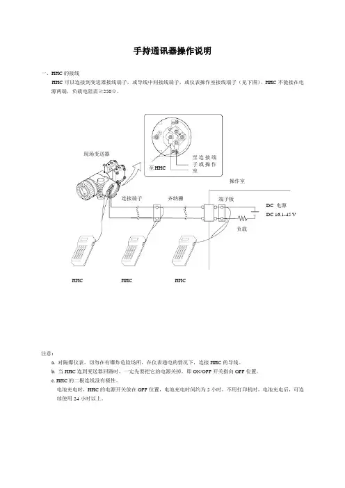
手持通讯器操作说明一、HHC 的接线HHC 可以连接到变送器接线端子,或导线中间接线端子,或仪表操作室接线端子(见下图)。
HHC 不能接在电源两端,负载电阻需≥250Ω。
注意:a. 对隔爆仪表,切勿在有爆炸危险场所,在仪表通电的情况下,连接HHC 的导线。
b. 当HHC 连到变送器回路时,一定先要把它的电源关掉,即ON/OFF 开关指向OFF 位置。
c. HHC 的二根连线没有极性。
电池充电时,HHC 的电源开关放在OFF 位置,电池充电时间约为5小时,不用打印机时,电池充电后,可连续使用24小时以上。
至连接端子或操作室负载端子板连接端子 现场变送器齐纳栅操作室DC 电源 DC 16.1-45 V至HHCHHCHHC HHC操作流程表下表为6.0版本的手持通讯器FXW的操作流程表(FXW□□□□1-□3),低于6.0版的FXW不可用于FXW-A Ⅱ系列变送器,如需升级,请更换内部ROM。
二、HHC的操作方法HHC的操作方法是指按操作流程表,逐项进行设定、修改或显示。
全部共18项,下面逐项加以说明:0:PUSH NENU KEY (按菜单键)打开电源,显示器在显示有关信息和准备后,显示0:PUSH MENUKEY (请按菜单键)画面。
1:TAG NO(工位号)在0:PUSH MENU KEY画面下按MENU键,显示器即出现1:TAG NO,即设定仪表位号画面。
设定方法如下:按CHNG键,显示器即出现1-1:TAGCHANGE (工位号修改)画面,并出现光标。
用户根据光标位置,键写变送器的工位号。
按ALHA键,再按需要的字(每次这样)。
若某个字母或数字按错了,则可用或键移动光标,重新键写。
键写完毕,按ENT键,确认设定是否准确,若准确,再按ENT键,设定或修改的数据便进入变送器。
若修改有误,则按CL(清除)键,重新修改。
注:在设定时,用钥匙将键开关打开。
2:TYPE(型号设定)仪表位号设定完以后,按往下进行键INC。
HART通信器是一种便携式的终端,它与采用HART通信协议的仪表一起使用,对其进行设定,更改和显示,它可监控输入/输出值和自诊断结果。
设定恒定电流的输出和调零。
当系统开动或维持操作时,只要把HART通信器接在4~20mA通信信号线上,就可以使用。
特点:■ 在线监控和通信通信期间,调制信号不会中断4~20mA DC信号■ 与采用HART通信协议的仪表可共用HART通信器能与采用HART通信协议的所有仪表一起使用■ 操作方便大显示屏幕(4行,每行18个字符),采用中文显示,用户看了一目了然,设定和更改方便■ 信息自诊断/保护功能自检查功能格式化密码保护低电压报警显示标准技术规格:装置的技术规格适用仪表:ROSEMOUNT1151 , ROSEMOUNT3051ABB日本富士YOKOGAWA EJA(带HART通信协议)等进口压力变送器DS-1151,DS-3351HK1151 , HK3151等国产智能压力变送器通信信号的连接:专用线缆,长1.1m(3.6ft)通信线:长度:1Km(0.62英里)(0.75~1.25mm2)负载电阻:250~600Ω负载电容:0.22uF以下负载电感:3.3mH以下与电源线的间距:15cm以上(避免平行走线)显示:128*64点阵液晶显示控制:触摸开关(4个方向键,19个功能键,一个电源开关)电源:4支1.2V可充电电池尺寸:180*80*54mm (长*宽*高)重量:700g功能说明基本功能:■ 设定、更改和显示各种参数,HART通信■ 恒定电流输出■ 调零附加功能:■ 格式化保护需要输入密码才能进行格式化■ 电池报警LCD显示的报警信息可提示电池电压偏低■ LCD对比度调节正常工作条件环境温度: -15~55℃存储条件:环境温度:0~50℃附件:■ 通信电缆:壹根,分别带一个弹簧夹。
■ 4只1.5V电池■ 手提包■ 说明书■ 250偶坶电阻EMC认可标准:EMI(辐射)—EN55011:1991hart475手操器 Rosemount罗斯蒙特HART475手操器 产品介绍 hart475手操器通讯器,艾默生过程管理的新型的475现场通讯器,是罗斯蒙特hart375手操器的改良升级型号,它即支持HART 通讯协议,也支持基金会现场总线通讯协议,并具有通用、可靠、便携、本安、易于升级等特点。

1300 Henley CourtPullman, WA 99163509.334.6306www.store. https:///designspark/homePmod™ HAT Adapter Reference ManualThis manual applies to the Pmod HAT Adapter Rev. BOverviewThe Pmod HAT Adapter makes it easy to connect Digilent Pmods to a Raspberry Pi. It supports plug-and-play functionality, only requiring that the host Raspberry Pi be booted with the Pmod HAT attached. The Pmod HAT has three 2×6 Digilent Pmod ports and provides access to additional I/O available via the Raspberry Pi 40-pin GPIO connector. The Pmod HAT Adapter comes with example Python libraries hosted on DesignSpark. See the Software Support section below for more information.The Pmod HAT Adapter RS Stock No 1448419 Features include:•Provides access to full line of Digilent Pmod peripheral modules.•Enables use of up to three Pmods at a time.•Supports SPI, UART, I2C, and GPIO connections.•Optionally powered through a 5V barrel jack.•Follows Raspberry Pi HAT specification. See the Raspberry Pi HAT Introduction for moredetails.The Pmod HAT Adapter is compatible with allRaspberry Pi boards that use the 40-pin GPIO connector:•Raspberry Pi Model A+•Raspberry Pi Model B+•Raspberry Pi 2 B•Raspberry Pi 3 B•Raspberry Pi Zero W•Raspberry Pi Zero1 Functional Description1.1 Connectors and Jumpers40 Pin Raspberry Pi GPIO Connector (J1): This connector is used to attach the Pmod HAT to the host Raspberry Pi and provide access to each of the connector pins. Most of these 40 pins are shared with the Pmod ports. The Pmod ports are not intended to be used simultaneously with an additional HAT. However, five GPIO pins (22-25 and 27) are unused by the Pmod HAT Adapter. These pins are available for use by other HATs or as user GPIO. Pmod port pins are connected to the 40-pin GPIO connector as seen in the Pinout Table Appendix.External Power Jack (J2): This connector can be used to provide power to the Pmod HAT adapter and the attached Raspberry PI. See the Power section below for more information.Pmod Port JA: The first of the three 2×6 Pmod host ports, this port supports SPI and GPIO Pmods.Pmod Port JB: The second of the three 2×6 Pmod host ports, this port supports SPI and GPIO Pmods, as well as 6-pin I2C Pmods on the bottom row.Pmod Port JC: The third of the three 2×6 Pmod host ports, this port supports UART and GPIO Pmods.Jumpers JP1 & JP2: These jumpers enable pullup resistors for the Pmod Port JB I2C pins when shorted.Jumper JP3: This jumper enables writing to the onboard EEPROM containing the device tree fragment and other information used to configure the Raspberry Pi OS and drivers. Shorting this jumper is for advanced use only. See the Raspberry Pi HAT Introduction for more details.1.2 PowerThe Pmod HAT Adapter can be powered either from the Raspberry Pi through the 40-pin GPIO connector's two 5V pins, or from an external 5V supply through the power jack. If an external supply is used, it must be able to provide 1.3 Amps of current. In addition, each Pmod GPIO pin can supply at most 16mA of current.Important!Make sure to never connect both the Pmod HAT Adapter and Raspberry Pi's power supplies at the same time. When changing power supplies, make sure to first fully disconnect the original supply2 Software SupportRS Components has produced the DesignSpark Pmod Library which can be used with a Raspberry Pi to control Pmods through the Pmod HAT Adapter using the Python programming language. Documentation and downloads for this library can be found at the following locations:•Python library at .•Documentation and installation instructions on Readthedocs.io.•Source code at .•RS Components Stock No 1448419Appendix: Pinout TablesRaspberry Pi 40-Pin Connector PinoutImage Courtesy of the Raspberry Pi Foundation licensed under CC BY-SA.Bottom Row Top Row40-Pin GPIO Connector Pin #40-Pin GPIOConnector Pin NamePmod Pin 40-Pin GPIOConnector Pin #40-Pin GPIOConnector Pin NamePmod Pin13V3 N/C 2 5V N/C 3GPIO02 JB10 4 5V N/C 5GPIO03 JB9 6 GND GND 7GPIO04 JC7 8 GPIO14 JC2 9GND GND 10 GPIO15 JC3 11GPIO17 JC4 12 GPIO18 JA10 13GPIO27 N/C 14 GND GND 15GPIO22 N/C 16 GPIO23 N/C 173V3 N/C 18 GPIO24 N/C 19GPIO10 JB2 20 GND GND 21GPIO09 JB3 22 GPIO25 N/C 23GPIO11 JB4 24 GPIO08 JA1 25GND GND 26 GPIO07 JB1 27ID EEPROM N/C 28 ID EEPROM N/C 29GPIO05 JC9 30 GND GND 31GPIO06 JC10 32 GPIO12 JC8 33GPIO13 JB8 34 GND GND 35GPIO19 JA7 36 GPIO16 JC1 37GPIO26 JB7 38 GPIO20 JA9 39GND GND 40 GPIO21 JA8Pmod Pinout TableJAPmod Pin #40-Pin GPIO Connector Pin #40-Pin GPIO Connector Pin Name 124 SPI0_CE0/GPIO08219 SPI0_MOSI/GPIO10321 SPI0_MISO/GPIO09423 SPI0_CLK/GPIO11735 PCM_FS/GPIO19/PWM1840 PCM_DOUT/GPIO21/GPCLK1938 PCM_DIN/GPIO20/GPCLK01012 PCM_CLK/GPIO18/PWM0JBPmod Pin #40-pin GPIO Connector Pin #40-Pin GPIO Connector Pin Name1 26 SPI0_CE1/GPIO072 19 SPI0_MOSI/GPIO103 21 SPI0_MISO/GPIO094 23 SPI0_CLK/GPIO117 37 GPIO268 33 PWM1/GPIO139 5 SCL1/GPIO03*10 3 SDA1/GPIO02*JCPmod Pin #40-Pin GPIO Connector Pin #40-Pin GPIO Connector Pin Name1 36 CTS0/GPIO162 8 TXD0/GPIO143 10 RXD0/GPIO154 11 RTS0/GPIO177 7 GPCLK0/GPIO048 32 PWM0/GPIO129 29 GPCLK1/GPIO0510 31 GPCLK2/GPIO06* Pullup resistors for pins SCL1 and SDA1 can be enabled by shorting jumpers JP1 and JP2, respectively.Pins #5 and #11 of each Pmod port are tied to Ground. Pins #6 and #12 of each Pmod port are tied to the HAT Adapter's 3V3 rail.。

HART编程器说明书1.1 接线 (3)1.2 LCD说明 (4)1.3 操作键 (4)1.4 编程器的在线与离线操作 (6)1.5 在线菜单 (11)1.6 编程器使用 (17)1 哈特编程器的通用功能哈特编程器(见图1.1-1)是以HART(Highway Addressable Remote Transducer 可寻址远程传感器通路)通信协议为基础的手持式通信设备,用以与所有基于HART协议微处理器类型的监控仪表进行通信。
第1节主要讲述了哈特编程器的接线、LCD显示内容、键盘、在线监控菜单、离线监控菜单,电池盒、存贮模块、数据包、维护与两千年问题。
对编程器的功能也作简要说明。
第2节讲述该编程器(Fisher-Rosemount's HART设备)的功能与通常在液晶显示上显示的内容。
第3节按树状菜单形式对编程器应用于Fisher-Rosemount's HART设备的典型实例进行说明。
操作键1.1 接线编程器通过4~20mA信号回路与现场仪器仪表进行通讯,但应注意要在电源与仪表间连接一个不小于250 Ω的电阻。
HART通信协议使用频移键控FSK(Frequency Shift Keying)技术,将数字信号变换为音频信号,叠加到现场变送器和控制室之间的4~20mA电流环上来作数字通信。
协议规定的信号频率(1200Hz代表1,2200Hz代表0)和传输速率(1200bit/s)符合美国Bell 202标准。
这些音频正弦波的平均值为零,所以在现存的模拟信号中不增加直流成分,因此,在2根线上可以同时传送互不影响的模拟和数字信号。
正是由于HART协议的这种优点,使它成为工业现场广泛应用的、事实上的工业标准。
哈特通信员能从控制室、仪表站或任何线路终端与现场仪器仪表进行通讯,接线均接在图1.1-2所示后面板的接线孔上。
编程器可与PC机联接,联接应配用专门的适配器且连在编程器的串口上,注意联接串口的环境应无爆炸的危险否则会造成设备与人身的伤害。
现场通讯器用户手册HART475C旭盛电工(江苏)有限公司目录第一章简介 (2)第二章基本使用 (3)2.1现场通讯器的基本性能和功能 (3)2.2开机注意事项 (4)2.3键区的使用和说明 (5)第三章在线操作菜单 (6)3.1检测菜单 (6)3.1.1轮询检测 (6)3.1.2按轮询号检测 (7)3.1.3选择设备类型 (7)3.2压力变送器主菜单 (8)3.2.1过程变量 (8)3.2.2组态与测试 (9)3.2.3特征化 (12)3.2.4校准 (19)3.2.5显示模式 (21)3.2.6通用格式化 (22)3.3电磁流量计主菜单 (23)3.4涡街流量计主菜单 (23)3.5靶式流量计/浮筒液位计主菜单 (23)3.6金转流量计主菜单 (23)3.7通用主菜单 (23)第四章故障排除 (24)4.1故障介绍和排除方法 (24)4.2提示界面 (25)附一 (27)附二 (28)附三 (34)第一章简介感谢您使用HART现场通讯器,本通讯器适合HART协议智能变送器的通讯操作,与HART275、HART375、HART475兼容,具有极好的兼容性,可通讯1151,3051,EJA,ABB及流量方面的HART协议的进口仪表。
完全兼容国产的各种智能变送器。
该手册介绍了现场通讯器基本的使用、连接和操作方面的内容以及故障的排除和在使用过程中应该注意的事项。
在使用HART现场通讯器之前,请阅读该该操作手册,为了更好发挥该产品的最佳性能,在使用或维修本产品之前,请深入掌握相应的内容。
如若设备需要维修,请联系我们公司。
我们将竭尽所能为您服务。
该设备配备:手操器一台电池一块包一个充电器一部通讯线缆一条操作手册一本250欧姆电阻一支第二章基本使用2.1现场通讯器的基本性能和功能2.2开机注意事项在开机前,请确保以下几点:现场通讯器示图开/关键数字字母按键区显示区PV 键左中右选择键四个导航键确认键充电器接口通讯电缆电池显示·该现场通讯器没有物理机械损坏·电池已充满电。
HART-MODBUS智能转换器(HART通道相互隔离)SM100-W使用说明书嘉兴市松茂电子有限公司目录1、SM100-W智能转换器介绍 (2)1.1产品简介 (2)1.2产品特点 (2)1.3主要参数 (2)2、SM100-W智能转换器实物图及指示灯功能 (3)2.1实物图 (3)2.2产品选型 (3)2.3接线图 (4)2.4接线端口及型号标记介绍 (4)2.5指示灯说明 (4)3、配置软件功能介绍及操作步骤 (5)3.1通讯连接 (5)3.2配置以太网络参数 (7)3.3系统参数界面功能介绍 (10)3.4透明工作方式界面功能介绍 (11)3.5MODBUS参数配置界面功能介绍 (12)3.6用ModScan32测试软件读取数据 (13)4、服务与保修 (14)SM100-W HART智能转换器可通讯仪表(全部现场测试通过)1)罗斯蒙特系列HART仪表3300雷达液位计1700(2700)变送器8700系列电磁流量计5400系列雷达液位计248型一休化温度变送器多变量变送器1151系列压力变送器8800C涡街流量计2)西门子系HART仪表MG6000电磁流计FUS06超声波流量计FUS010超声波流量计MASS6000质量流量计7ME5033气流量计7ME5034气流量计HR02(FN34)料位计3)科隆系列HART仪表IF100电磁流量计IF300电磁流量计IF090电磁流量计OPTISWIRL4070流量计BM700雷达物位计VFC070气体流量计UFC500流量计4)ABB系列HART仪表WateMasterFEX10流量计FEP300流量计2600T压力变送器FEP300流量计FEH300流量计AM54转子流量计5)E+H系列HART仪表NMS53X系列流量计FMR53X系列物位计FMU40X系列料位计PDM23X(26X)差压变送器FMR23X(24x)系列液位计Prowirl72质量流计6)横河系列HART仪表YOKOGAWA AX系列电磁流量计EJA系列压力变送器7)其他类型HART仪表LD301系列智能压力表MSP400R超声波液位变送器VT5000菲舍波特涡街流量计F56系列金属管浮子流计HT50系列金属管浮子流量计VAG雷达料位计东芝电磁流计1、SM100-W智能转换器介绍1.1产品简介SM100-W系列HART智能转换器是采用ARM微处理器、HART协议调制解调专用芯片并结合大量的实践经验所研发的产品。
HART-AdapterHART FSK / PC modem— USB—Ex(Haz.) and Non-Ex(Haz.) applicationsHART FSK / PC modem II— RS 232C—Non-Ex(Haz.) applications HART LCI / PC adapter — with small connectorHART-Adapter2 10/63-6.71-EN | HART-AdapterNHA121-NX, NHA121-NO HART FSK / PC-USB-ModemAdapterThe modem NHA121-NX / -NO is designed to provide a communication link between a desktop computer or PC notebook and the HART field device. The PC can be taken into the field and connected with the HART network within seconds thanks to the USB plug & play features. Mobile data acquisition as well as parameterisation are preferred operational areas.For the use in hazardous areas we deliver an intrinsic safe, ATEX certified version: NHA121-NX. It is functionally equivalent to the NHA121-NO type.Hardware ProfileThe USB modem supports the HART specification standard. Its connector cable comes with a twisted pair wire 2-pin terminal block to dual test clips. The modem can work as primary as well as secondary Master. The modem is available with opto-isolation to the HART network. The device is USB-bus powered, thus not depending on external power supplies. The communication does not interfere with the normal operation of the field device. The interface is housed in a compact shell that attaches securely to the USB port.SoftwareThe interface supports the Windows operation systems and it can work like a serial modem. It offers a serial COM-port so that already existing applications can be used without any changes.Further more a device type manager (DTM), incl. license key, is included. The DTM provides communication betweendevices on the HART bus and their DTMs. With its help set-up and configuration of the HART network can be done.Device Type Manager for HART Networks (optional)The software package HART FDT consists of the component: — CommunicationDTM CommDTM for NHA121-NX / -NOCommDTMThe CommDTM is compliant with the current FDT specification 1.2.1. It requires the NHA121-NX/-NO as basic hardware. The DTM takes care of its management and configuration. It replaces the vendor specific configuration software with a standard FDT approach.The CommDTM can be compared to a device driver which facilitates the communication between the field devices at the HART bus and their device DTMs. It therefore supports the commissioning of the field devices from one central workstation.The communication interface can be employed as primary as well as secondary master. The configuration window of the CommDTM enables the user to switch between the twooptions. The retry limit and the number of preambles may also be set through the configuration window.FeaturesThe function "Device List" allows the scan for devicesattached to the HART bus. All devices, which can be reached through a polling address, are listed. Additional information is available for every device found, including the tag, the vendor identification, the device type and the device ID.In order to change the poll address of a device, it can be selected from the device list. A new window opens which permits the setting of the new poll address. The CommDTM secures that the device is not currently in use by anyDeviceDTM. The device state is indicated in the device list. The CommDTM also checks whether the new poll address was already taken by another device, preventing an address overlay between different devicesExplosion protection for NHA121-NXApproved for connection to an intrinsically safe transmitter circuit.Technical dataModem-Typ NHA121-NX NHA121-NOM10678M10679PC-Interface USBOperational Area mobile / stationaryModem Chip HT2012Connector 2-pin test clipsTransmission Rate 1200 Bit/s (600 Bit/s optional)DTM HART Version 5 or higherOperating system Windows 7, Windows Vista, Windows XP und Windows 2000 (32-bit versions only)ATEXCE Certification CE,ATEX II (2) G [Ex ia] IIC -Delivery Contents Hardware with fix USB cable and pluggable test clips, Driver and Configuration Software,CommDTM, DTM License key, Documentation on CDHART-Adapter | 10/63-6.71-EN 3HART-Adapter4 10/63-6.71-EN | HART-AdapterNHA102-NOTechnical dataElectrical data Voltage U ss 0,6 V, average-free Current < 3 mA Power max 1,5 mW Frequency 1,2 and 2,2 kHz Electromagnetic compatibility (EMC)to IEC 801 / NAMUR— HART-FSK-Modem II— Digital communication through FSK (standard HART Protocol)— Communication by tapping at the analog 4 ... 20 mA signal transmission— Potential separation between the PC and the device — Average-free signal transmission, hence unaffected 4 ... 20 mA output signalEnvironmental capabilities Operating temperature 0 ... 45 °C Storage temperature -20 ... 55 °C Air humidity< 80 %— Digital signals, “0“ = 2.2 kHz; “1“ = 1.2 kHzApplicationsThe FSK modem acts as a sort of digital communication“translator“ between the computer and the transmitter. Power supply is realized automatically via the serial RS 232Cinterface of the computer, in parallel with data transmission.HousingMaterial Plastic Degree of protection IP 20Connectors9-pin or 25-pin Sub-D socket (PC side), screw terminals and 0.75 m cables with clip-on connectors (device side)Dimensions 55 mm x 55 mm x 17 mm Weightapprox. 0,1 kgCommunication is done by tapping at any point of the analog 4 ... 20 mA signal transmission. No special attention has to be paid to polarity for the 2-pole tap. The devices are HART-compatible, i. e. they have a certain internal resistance, which must be considered. Power for data tapping is supplied in parallel from the PC via the RS 232 C interface.The modem has a 9-pin or 25-pin Sub-D socket on the PC side and is connected to the transmitter via 0.75 m cables with clip-on connectors on the device side. The cables connect to the modem through screw terminals.M10680Fig. 1M10681Fig. 2:Connection diagram, with 250 Ω communication resistor1 Internal resistance for supply unit > 250 Ω(resistance can also be realized as external communication resistor) 2 Internal resistance for signal source >10 kΩFig. 3:Connection diagram, without 250 Ω communication resistor2 Internal resistance for signal source >10 kΩHART-Adapter | 10/63-6.71-EN 5HART-Adapter6 10/63-6.71-EN | HART-AdapterNHA201-NOM10683LCI adapterIn offline mode (e. g. in the shop or lab) the local communication interface (LCI) can be used forparameterization. In this case the transmitter is powered via the PC. In online mode local communication is possible without affecting the analog output.The LCI adapter is used to connect the transmitter to the PC.Universal through:— 9-pin or 25-pin SUB D connectorFig. 4with small connector for:— Positioner, TEU421, TEU471, BCI100 (Contrans I), Power Transducer SU.Ordering informationHART-FSK / PC-adapter Catalog No.1)3KDE636710L0001NHA121-NX (14290-0203) (Note USB / HART FSK Modem,IS input II (2) G [Ex ia] IIC, electrical isolation,for Windows 7, Windows Vista, Windows XP and Windows 2000 (32-bit versions),to connect a tool to HART devices via a PC / Notebookincl. standard driver and Common DTM (FDT 1.2.1), DTM license key,USB cable, connection cable with clips and manual (*.pdf)NHA121-NO (14290-0105) (Note1)3KDE636710L0002USB / HART FSK Modem,Electrical isolation,for Windows 7, Windows Vista, Windows XP and Windows 2000 (32-bit versions),to connect a tool to HART devices via a PC / Notebookincl. standard driver and Common DTM (FDT 1.2.1), DTM license key,USB cable, connection cable with clips and manual (*.pdf)NHA102-NO (Note 1)7957838 RS 232C / HART FSK Modem II,connector version, with connection clipsHART-LCI / PC-adapter BestellnummerNHA201-NO319621 RS 232C / LCI-Adapter with small connector,for positioners, TEU421, TEU471, BCI100 (Contrans I modules),Power Transducer SUNote 1: for configuration of general HART-instruments and TH(x)01, TS(x)02, BCI100 (Contrans I) backplaneHART-Adapter | 10/63-6.71-EN 7Contact us10/63-6.71-E N R e v . K 05.2011NoteWe reserve the right to make technical changes or modify the contents of this document without prior notice. With regard to purchase orders, the agreed particulars shall prevail. ABB does not accept any responsibility whatsoever for potential errors or possible lack of information in this document.We reserve all rights in this document and in the subject matter and illustrations contained therein. Any reproduction, disclosure to third parties or utilization of its contents - in whole or in parts – is forbidden without prior written consent of ABB.Copyright© 2011 ABB All rights reserved3KXN671000R1001ABB Automation Products GmbH Service Instrumentation Kallstadter Straße 168309 Mannheim, GermanyCustomer Service Center: +49 180 5 222 580* E-Mail:*************************.com*14 cents/minute from German landlines, max. 42 cents/minute from mobiles.® Windows and Windows Vista are trademarks ofMicrosoft Corporation.® HART is a trademark of HART CommunicationFoundation.。
Products Solutions Services TI00026S/04/EN/22.1771396550Technical InformationWirelessHART Adapter SWA70Smart WirelessHART interface modulewith power supply for field devicesApplicationThe WirelessHART Adapter SWA70 is an interface module for the wirelesstransmission of 4 to 20 mA/HART signals from connected field devices to aWirelessHART Fieldgate. It is powered by either a battery pack or power supply units.The WirelessHART Adapter can be used in hazardous and non-hazardous area forapplications, such as:•Process optimization:By connecting the WirelessHART Adapter, it is possible to monitor and optimizeplant sections with less cost and effort.•Level monitoring in tanks and silos:Measured values together with the device and battery status are transmitted atregular intervals to a higher-level system.•Plant condition monitoring:Wireless devices are mounted at critical points in the plant which are not normallyconnected to the control room due to their limited accessibility or wiring costs.Improved data flow and diagnostics increase plant reliability and safety.Your benefitsThe flexible adapter concept offers the following advantages:•HART devices are quickly upgraded to WirelessHART technology•Fast integration of 4 to 20 mA field devices into a WirelessHART network•One 4 to 20 mA field device and up to four HART field devices in multidrop mode canbe connected to a WirelessHART Adapter•Burst mode and event notification supported•Remote and difficult-to-access HART devices are connected to the control roomwithout expensive cabling•Easy planning, quick installation and integrationWirelessHART Adapter SWA702Function and system designWirelessHART WirelessHART adds wireless capabilities to the HART protocol, while ensuring compatibility withexisting HART devices, commands and tools.A WirelessHART network comprises:•Wireless field devices•Wired field devices with a connected WirelessHART Adapter•Gateways responsible for communication between devices and host applications•Network and Safety Manager responsible for configuring, managing and monitoring the networkThe WirelessHART protocol may not be used to replace the wiring in the case of safety applicationswith a control function.WirelessHART Adapter SWA70The WirelessHART Adapter SWA70 acts as an add-on interface for wireless communication with HART field devices or 4 to 20 mA field devices.It is powered by either a battery pack, a wide range power unit or a DC power unit. The DC power unit can use solar power, for example. A special long-life, high-power battery is used as the battery.The WirelessHART Adapter SWA70 supports the following functions:•Power supply for a HART field device or a 4 to 20 mA field device•Power supply of up to four HART devices in the multidrop mode with a wide range power unit •Connection of up to four externally powered HART field devices in the multidrop mode •Scaling of the current signal from a connected 4 to 20 mA field device•Burst mode and event notification for the WirelessHART Adapter and the connected field devicesSystem design The WirelessHART Adapter SWA70 transmits information to a host application via a WirelessHARTFieldgate. The figure below shows a typical WirelessHART network architecture.WirelessHART Adapter SWA703Inputs (wired interface)InputsCommunication interface•HART interface to configure the WirelessHART Adapter with a HART modem •LPI interface (internal interface for the manufacturing and diagnosis)Protocol version HART Version 7.3 (backwards compatible with earlier HART versions)Transmission rate 1200bits/s Field device power supplyConnection of externally powered devices on terminals 2 (6)max. permissible input current terminals 2...6: 100 mA max. permissible input voltage terminals 2...6: 30 V DCOnly the connection of power supply units of the protection class II is permissible.TerminalsThe WirelessHART Adapter has a terminal block with screw terminals 1-6 and 2 eyelets 7 and 8 for connection purposes.One input channel for:•One point-to-point connection with a HART field device or •One point-to-point connection with a 4-20 mA field device or•Up to four HART field devices connected in multidrop mode if a wide range power unit is used. The wide range power unit provides 24V to power the field devices.Current: 4 to 20 mA (according to NAMUR recommendation NE 43) or 4 mA if only one field device is connected in multidrop mode Error current:I ≤ 3.6 mA or I ≥ 21 mAProtection:Short-circuit protection, triggered if currents > 25 mA Terminal voltage:8 to 23 V DC, configurableApplicationTerminal assignmentRemarksConnection valuesPower supply to a loop-powered field device1 (+) and2 (–)•Current measurementand HART communica-tion where applicable •Loop current flows through the adapter •4 to 20 mA (according to NAMUR NE43)•8-23 V power supply for field device, configurable, see the following diagram •Integrated load: 250Ohm Integration of theWirelessHART Adapter into a current loop2 (+) and3 (–)•Current measurement and HART communica-tion where applicable •Loop current flowsthrough the adapter•4 to 20 mA (according toNAMUR NE43)•Integrated load: 250OhmIntegration of theWirelessHART Adapter into a current loop5 and 6•Integration into HARTcommunication•Loop current does notflow through the adapter •Input impedance for HART communication: > 10kOhm at 1700Hz •DC input impedance: 1 MOhmstrommessung 1 – 2strommessung 2 – 3WirelessHART Adapter SWA704Field device power supply through SWA70Output (wireless interface)Communication interfaceWirelessHART communication interface (IEC 62591),HART version 7.3 (backwards compatible with earlier HART versions)Transmission rate Nominal 250kBits/s Operating frequency 2.4GHz (ISM band)RangeUp to 250m outdoors, up to 50m indoorsTransmission power Can be configured for 0 dBm or 10dBm to adapt to national regulationsDevice variablesUp to 10 bursts can be configured in accordance with the HART specification. Up to eight device variables per burst can be configured depending on user transmission requirements.Example:•HART field device: device variables• 4 to 20 mA field device: scaled or linearized process values•WirelessHART Adapter: scaled loop current and other variables, choose from: estimated batterylife, battery voltage, energy used, adapter temperatureAdditional functions•Event notification, configurable for up to eight variables from the WirelessHART adapter and/or connected field devices•Error notification and scaling or linearization of the 4 to 20mA signal of the connected analog field device•Monitoring of energy consumption •Locking of device parameterizationConfiguration of theWirelessHART Adapter with a HART modem7 and 8 Temporary connection of the modem via eyelets•Input impedance for HART communication: > 10kOhm at 1700Hz•DC input impedance: >1MOhmApplicationTerminal assignmentRemarksConnection values1SWA70 non-Ex versions with 4 to 20 mA field device 2SWA70 non-Ex versions with HART field device3SWA70 Ex versions with HART field device or 4 to 20 mA field device12141618202224Field device power supply [V]Loop current [mA]48121620123WirelessHART Adapter SWA705Diagnostics Diagnostics function in accordance with NAMUR NE 107, ASM and HART recommendationsPower supplyVersions•Battery unit BU 191: special long-life high-power lithium-thionyl chloride battery unit •Wide range power unit•DC power unit, e.g. solar-poweredPower supply•Wide range power unit: 24V to 230V AC/DC ± 10 %, 50/60Hz •DC power unit: 8 to 50V DCIn the event of an external power supply failure, wireless communication is maintained for at least one hour thanks to an internal power supply system.Current consumption•Wide range power unit: <350mA, 1 A slow-blow back-up fuse must be installed by the customer onsite•DC power unit: <250mA, 1 A slow-blow back-up fuse must be installed by the customer onsite Power consumption•Wide range power unit: max. active power 7W / max. reactive power 12VA with alternating voltage •DC power unit: <2.2W Battery capacity•19Ah nominal capacity at 20°C •7.2 V DC•Lithium metal content: 10gBattery lifeUp to 10 years, depending on update rate of process variables, field device type and environmental conditionsCableField device connection•Mounted directly on field devices: cable supplied (0.25 mm 2)•Remote mounting: standard installation cable (0.25 mm 2)Wide range power unit or DC power unit (M12 socket): 0.75 mm 2Performance characteristicsReference operating conditionsAccording to IEC 61298 Part 2Maximum measured error 4 to 20mA circuit: 0.125% of measuring range Influence of ambient temperature4 to 20 mA circuit:5 μA/10 KWirelessHART Adapter SWA706Operating conditionsApplication range The WirelessHART adapter SWA70 is a smart wireless module designed for the wireless transmissionof 4 to 20 mA HART signals from connected field devices to a WirelessHART Fieldgate SWG70.The WirelessHART protocol may not be used to replace the wiring in the case of safety applicationswith a control function.Installation conditionsInstallation•Directly on field device•Remotely on a wall or pipe using optional mounting bracketInstallation instructions (recommendations)•Consider the range. See Seite 4, Range.•Avoid mounting too near walls, pipes and heavy-duty electrical equipment.•Mount in line of sight with a neighboring adapter and Fieldgate. •Consider the development of the Fresnel zone.•Align antenna so that it is completely vertical.Protection against lightning•Do not mount the WirelessHART Adapter at the highest point in the plant.•WirelessHART Adapter with metal housing: connect protective ground to protective groundconnection of the housing. Protective ground in 2.5 mm2.EnvironmentClimate class EN 60721-3-4: 4K4H, suitable for stationary use at unprotected outdoor locationsAmbient temperature range•–40 to +80°C (–40 to +176°F)•Ex versions –40 to +60°C (–40 to +146°F) for temperature class T3•Ex versions –40 to+50°C (–40 to+122°F) for temperature class T4•The battery pack capacity decreases significantly at temperatures below –30°C (–22°F).Storage temperature•WirelessHART Adapter without battery unit: –40 to +85°C (–40 to +185°F)•WirelessHART Adapter with disconnected battery unit: –40 to +25°C (–40 to +77°F)•Battery unit BU 191: –40 to +25°C (–40 to +77°F)Vibration resistance EN 60068-2-64: 20Hz ≤ f ≤ 2000Hz: 0.01g²/HzShock resistance EN 60068-2-27: 15g, 11msElectromagnetic compatibility All modules are suitable for industrial use and meet the requirements of EU Directive 2014/30/EU "Electromagnetic compatibility":•Emission:•With wide range power unit: EN 61326-1: 2013, Class A•With DC power unit or battery unit: EN 61326-1: 2013, Class B•Interference immunity:•EN 61326-1: 2013 Tab. 2 (industry)•Namur recommendation EMC (NE21)WirelessHART Adapter SWA707Temperature restrictionsThe temperature restrictions listed are based on the assumption that more than 30% battery capacity is remaining.Ex version, 4 to 20 mA supply modeThe application range is limited in the event of high measuring currents close to 22 mA.Ex version with fixed current of 4 mA (multidrop mode)Non-Ex version,4 to 20 mA supply modeThe application range is limited in the event of high measuring currents close to 22 mA.Current strength in mA 422T e r m i n a l v o l t a g e o f f i e l d d e v i c e i n V8–40°C –30°C 10–40°C –30°C 12–40°C –30°C 14–40°C –25°C 16–40°C –25°C18–40°C 20–40°C 22–40°CStart-up current in mASee Operating Instructions, "Field device power supply" section.46810121416182022T e r m i n a l v o l t a g e o f f i e l d d e v i c e i n V8–40°C –40°C –40°C –40°C –40°C –40°C –40°C –35°C –25°C –15°C 10–40°C –40°C –40°C –40°C –40°C –40°C –40°C –30°C –15°C–10°C12–40°C –40°C –40°C –40°C –40°C –40°C –35°C –20°C 14–40°C –40°C –40°C –40°C –40°C –35°C –25°C–10°C16–40°C –40°C –40°C –40°C –40°C –25°C18–40°C –40°C –40°C–30°C–5°C20–40°C–35°C22Current strength in mA 422T e r m i n a l v o l t a g e o f f i e l d d e v i c e i n V8–40°C –30°C 10–40°C –30°C 12–40°C –30°C 14–40°C –25°C 16–40°C –25°C18–40°C 20–40°C 22–40°CWirelessHART Adapter SWA708Non-Ex version with fixed current of 4 mA (multidrop mode)Mechanical constructionDesign/dimensionsWeight•Polyester housing with power supply unit: 0.785 kg •Aluminum housing with power supply unit: 0.9 kg •AISI 316L housing with power supply unit: 1.9 kgMaterials•Housing: polyester or aluminum or AISI 316L, see ordering information •Color of polyester and aluminum: light-gray, RAL 7035 with blue logo Degree of protection•Polyester housing F32: IP65/IP66; NEMA Type 4•Aluminum housing F33: IP67, NEMA Type 4X•AISI 316L housing F39: IP66/IP67, NEMA Type 4XConnection adaptersM20x1.5 to M20x1.5; M20x1.5 to G 1/2; M20x1.5 to NPT 1/2; M20x1.5 to NPT 3/4See ordering information AntennaOmnidirectional dipole antennaStart-up current in mASee Operating Instructions, "Field device power supply" section.46810121416182022T e r m i n a l v o l t a g e o f f i e l d d e v i c e i n V8–40°C –40°C –40°C –40°C –40°C –40°C –40°C –40°C –40°C –40°C 10–40°C –40°C –40°C –40°C –40°C –40°C –40°C –40°C –40°C –35°C 12–40°C –40°C –40°C –40°C –40°C –40°C –40°C –40°C –40°C –35°C 14–40°C –40°C –40°C –40°C –40°C –40°C –40°C –35°C –35°C –35°C16–40°C –40°C –40°C –40°C –40°C –40°C –40°C –35°C –20°C18–40°C –40°C –40°C –40°C –40°C –40°C –40°C–35°C20–40°C –40°C –40°C –40°C–40°C–35°C22–40°C–40°C–40°CDimensions in mm 25.4 mm = 1 inchWirelessHART Adapter SWA709OperationConfiguration•Local configuration with FieldCare or DeviceCare via modem and DTM for SWA70•Local operation with FieldXpert also in the hazardous area•Remote configuration with FieldCare via WirelessHART Fieldgate SWG70 and DTM for SWA70 and SWG70•Remote configuration with a software and a gateway based on the device description (DTM or DD)Display and operating elementsDisplay and operating elements in WirelessHART Adapter:•Push buttons for selecting various functions•LEDs for indicating communication status, battery status, voltage level and error messages Device addressCan be configured between 0 to 63 via DD or DTM, default address 15Ordering informationProduct structureDetailed information about the product structure is available:•In the Product Configurator on the Endress+Hauser website: → Enter "SWA70" as the search string → click the "WirelessHART Adapter SWA70" link → In the window on the right under "Device support", click the link "Configure your selected product"•From your Endress+Hauser Sales Center: DocumentationWirelessHART Adapter SWA70Certificates and approvalsCE markThe WirelessHART Adapter SWA70 meets the legal requirements of the relevant EU Directives.Endress+Hauser confirms successful testing of the WirelessHART Adapter SWA70 by affixing to it the CE mark.Ex approvalSee "Documentation" section.❑WirelessHART Adapter SWA70Operating Instructions BA00061S ❑WirelessHART solutions for real-world applicationsCompetence brochure CP00013S ❑WirelessHART Adapter SWA70Safety Instructions ATEX, IECEx XA01366F❑WirelessHART Fieldgate SWG70Operating Instructions BA00064S ❑WirelessHART Adapter SWA70Safety Instructions CSA XA00538F❑WirelessHART-Adapter SWA70Safety Instructions EAC Ex XA01505F-AWirelessHART Adapter SWA7010Radio approvalsEuropeThis device meets the requirements of the RED "Radio Equipment Directive" 2014/53/A and CanadaFCC ID: 2AIKP-SWA70A IC: 21533-SWA70AThis device has been tested and found to comply with the limits for a Class A digital device, pursuant to Part 15 of the FCC Rules. These limits are designed to provide reasonable protection against harmful interference when the device is operated in a commercial environment. This device generates, uses, and can radiate radio frequency energy and, if not installed and used in accordance with the instruction manual, may cause harmful interference to radio communications. Operation of this device in aresidential area is likely to cause harmful interference in which case the user will be required to correct the interference at his own expense.Changes or modifications made to this device not expressly approved by Endress+Hauser may void the FCC authorization to operate this device. This device must be installed to ensure a minimum antenna separation distance of 20 cm from all persons.This device complies with Part 15 of the FCC Rules and with Industry Canada license-exempt RSS standard(s).Operation is subject to the following two conditions:•this device may not cause harmful interference, and•this device must accept any interference received, including interference that may cause undesired operation.Le présent appareil est conforme aux CNR d'I ndustrie Canada applicables aux appareils radio exempts de licence.L'e xploitation est autorisée aux deux conditions suivantes:•l'a ppareil ne doit pas produire de brouillage, et•l'u tilisateur de l'a ppareil doit accepter tout brouillage radioélectrique subi, même si le brouillage est susceptible d'e n compromettre le fonctionnement.Brazil“Este equipamento opera em caráter secundário, isto é, não tem direito a proteção contra interferência prejudicial, mesmo de estações do mesmo tipo, e não pode causar interferência a sistemas operando em caráter primário”.Para maiores informações, consulte o site da ANATEL .brJapanThis device is granted pursuant to the Japanese Radio Law (電波法)This device should not be modified (otherwise the granted designation number will become invalid)MexicoLa operación de este equipo está sujeta a las siguientes dos condiciones:(1) es posible que este equipo o dispositivo no cause interferencia perjudicial y(2) este equipo o dispositivo debe aceptar cualquier interferencia, incluyendo la que pueda causar su operación no deseada.IFETEL: RCPENSW17-0342NOM: 1702CE03608 (wide range power supply)Modello SWA70WirelessHART Adapter SWA70Other approvals Other national approvals are available on requestCountry Approval/GuidelineBulgaria General authorization required for the use outdoors and in public.Italy General authorization necessary for the use outside of private terrain.Norway The operation can be restricted within a radius of 20 km from the centerof Ny-Alesund.Romania In case of operation as secondary device; a special license is required.Latvia The outdoor use of the transmission frequency band of 2,4 GHz requiresa national approval.11WirelessHART Adapter SWA70 。
HART-MODBUS智能转换器(HART通道相互隔离)SM100-W使用说明书嘉兴市松茂电子有限公司目录1、SM100-W智能转换器介绍 (2)1.1产品简介 (2)1.2产品特点 (2)1.3主要参数 (2)2、SM100-W智能转换器实物图及指示灯功能 (3)2.1实物图 (3)2.2产品选型 (3)2.3接线图 (4)2.4接线端口及型号标记介绍 (4)2.5指示灯说明 (4)3、配置软件功能介绍及操作步骤 (5)3.1通讯连接 (5)3.2配置以太网络参数 (7)3.3系统参数界面功能介绍 (10)3.4透明工作方式界面功能介绍 (11)3.5MODBUS参数配置界面功能介绍 (12)3.6用ModScan32测试软件读取数据 (13)4、服务与保修 (14)SM100-W HART智能转换器可通讯仪表(全部现场测试通过)1)罗斯蒙特系列HART仪表3300雷达液位计1700(2700)变送器8700系列电磁流量计5400系列雷达液位计248型一休化温度变送器多变量变送器1151系列压力变送器8800C涡街流量计2)西门子系HART仪表MG6000电磁流计FUS06超声波流量计FUS010超声波流量计MASS6000质量流量计7ME5033气流量计7ME5034气流量计HR02(FN34)料位计3)科隆系列HART仪表IF100电磁流量计IF300电磁流量计IF090电磁流量计OPTISWIRL4070流量计BM700雷达物位计VFC070气体流量计UFC500流量计4)ABB系列HART仪表WateMasterFEX10流量计FEP300流量计2600T压力变送器FEP300流量计FEH300流量计AM54转子流量计5)E+H系列HART仪表NMS53X系列流量计FMR53X系列物位计FMU40X系列料位计PDM23X(26X)差压变送器FMR23X(24x)系列液位计Prowirl72质量流计6)横河系列HART仪表YOKOGAWA AX系列电磁流量计EJA系列压力变送器7)其他类型HART仪表LD301系列智能压力表MSP400R超声波液位变送器VT5000菲舍波特涡街流量计F56系列金属管浮子流计HT50系列金属管浮子流量计VAG雷达料位计东芝电磁流计1、SM100-W智能转换器介绍1.1产品简介SM100-W系列HART智能转换器是采用ARM微处理器、HART协议调制解调专用芯片并结合大量的实践经验所研发的产品。
其按照工业产品要求进行设计,具有很高的可靠性及稳定性。
智能转换器配有标准的RS485接口和网关,能与有HART协议的智能仪表进行数据透明传输或者转换为MODBUS_RTU/ MODBUS_TCP协议读取数据,保证数据进行实时传输。
HART协议使用Bell202频移键控(FSK)标准,在4~20mA基础上叠加调制数字信号,使得HART 协议仪表在不干扰4~20mA模拟量信号的同时允许双向数据通讯。
SM100系列智能转换器就是数字信号与模拟信号进行双向调制解调的智能转换器。
1.2产品特点●配有标准的RS485通讯接口和网关,可以进行参数配置、更改通讯波特率及奇偶校验位。
它与HART总线上的1200通讯速度无关,从而提高了整个系统的运行速度。
●采用工业通用的模块外壳,便于安装及调试。
●配有专用配置软件,可以对SM100系列智能转换器进行参数配置,并且通过智能转换器,可以与HART协议智能仪表进行数据通讯。
●支持标准的MODBUS_RTU及MODBUS_TCP协议。
●支持同时连接多台HART协议智能仪表。
●每个HART通道相互隔离,不影响仪表电流输出。
●支持多种特殊HART协议智能仪表,并能自定义读取特殊HART仪表的指令。
●数据更新时间为1台0.8秒,如果接8台则6.4秒全部更新完一次数据。
●安装方式:可以标准轨道安装,也可以固定安装。
1.3主要参数●电源输入电压:DC12~24V,电源的波纹不得大于200mA,电流需提供100mA。
●外壳尺寸:长103mm×宽71mm×高43mm。
●工作环境温度:-20℃~+80℃。
●相对湿度:10%~80%。
2、SM100-W智能转换器实物图及指示灯功能2.1实物图2.2产品选型型号适用场合SM100-W 多台HART协议智能仪表被DCS系统或者PLC采集后,在不影响原来使用的情况下,采用SM100-W智能转换器直接取出HART协议数字信号,转换成RS485接口,MODBUS_RTU协议送至采集器系统。
SM100-W-N 多台HART协议智能仪表被DCS系统或者PLC采集后,在不影响原来使用的情况下,采用SM100-W-N智能转换器直接取出HART协议数字信号,转换成RS485接口MODBUS_RTU协议或者以太网接口MODBUS_TCP协议送至采集器系统。
2.3接线图2.4接线端口及型号标记介绍●POW、GND:电源接口接线端子,POW接电源正极,GND接电源负极。
●LOOP1+、LOOP1-~LOOP8+、LOOP8-:共八组HART仪表通讯接口接线端子。
●R485D+、R485D-:RS48D+接RSRS485A,RS485D-接RS485B。
●NET:以太网接口。
●R_485:RS485接口。
●N_NET:以太网接口。
●4CH:接4台HART智能仪表。
●8CH:接8台HART智能HART仪表。
2.5指示灯说明●H1指示灯:转换器与1号HART表通讯。
●H2指示灯:转换器与2号HART表通讯。
●H3指示灯:转换器与3号HART表通讯。
●H4指示灯:转换器与4号HART表通讯。
●H5指示灯:转换器与5号HART表通讯。
●H6指示灯:转换器与6号HART表通讯。
●H7指示灯:转换器与7号HART表通讯。
●H8指示灯:转换器与8号HART表通讯。
●R45指示灯:RS485接口发送数据。
●NET指示灯:以太网接口接收数据。
●POW电源指示灯:接通电源后常亮。
3、配置软件功能介绍及操作步骤3.1通讯连接1)根据上部分对端口的介绍,转换器连接电源、RS485线/网线,等待POW电源指示灯常亮之后即可进行参数配置。
2)打开配置调试软件,选择通讯连接方式:COM串口通讯、IP网络通讯。
当转换器未配置网关设备时,通讯连接方式选择COM串口通讯;当转换器配置有网关设备时,串口通讯及网络通讯方式都可以选择。
3)COM串口通讯连接RS485线,选择正确的端口号、波特率及校验位(默认波特率9600、校验位None),然后打开串口,点击“通讯查询”,在下方的“接收缓冲区”中查询到本台转换器的版本号,此时连接成功。
4)IP网络通讯连接网线,通过点击“网关参数配置及查询”来配置以太网参数,然后输入正确的目标IP 地址及端口号,点击“建立连接”,当显示“已连接”时表示连接成功。
注:以太网络参数配置可查看“3.2配置以太网络参数”。
3.2配置以太网络参数1)打开配置软件,通讯连接方式选择IP网络通讯,然后点击“网关参数配置及查询”,此时会弹出网关参数配置窗口。
2)在弹出的窗口中点击“搜索设备”,搜索本台转换器的网关设备,搜索结果显示在右上方白色窗口中。
3)点击搜索结果,模块的当前配置信息会显示在左侧的数据框中。
4)用户在计算机中查询本地Internet协议(TCP/IP)属性,根据查询结果进行以太网络参数设置。
其中串口波特率—115200,校验/数据/停止—NONE、8、1为固定值,不可更改。
IP地址的最后一个字节不同,用户可自行定义。
5)更改好参数后,点击“设置”,点击“存储数据”,保存配置好的以太网络参数。
最后点击“网关复位”,此时网关所有参数已全部配置完成。
3.3系统参数界面功能介绍此界面用于RS485通讯参数、模块工作方式、MODBUS从机地址、HART指令间隔时间等基本参数的设置与查询。
1)通讯接口类型:点击“HART智能转换器系统参数”,可以读取该转换器的通讯接口类型参数信息,其中RS485/RS485+NET表示转换器的通讯接口,4台/8台表示转换器最多可以连接的HART仪表台数。
2)参数初始化:可以将转换器的参数恢复到初始化状态。
3)通讯查询:可以查询转换器的版本号。
4)HART智能转换器系统参数:可以读取通讯接口类型、RS485通讯参数、模块工作方式、MODBUS从机地址、HART指令读数据速度等参数信息。
5)RS485通讯参数设置:用户根据实际情况,选择RS485通讯时的波特率和校验位(默认波特率9600、校验位None),然后点击“设置”。
设置成功后配置软件自动关闭串口,此时要重新选择设置好的波特率及校验位,打开串口,才能正常通讯。
6)MODBUS从机地址:输入3位数字的从机地址并点击“设置”。
7)模块工作方式:读取“透明工作方式”界面的数据时选择透明工作方式,读取“MODBUS参数配置”界面的数据时选择MODBUS_RTU仪表方式,然后点击“设置”。
注:“MODBUS参数配置”界面的模块工作方式设置框和此处的模块工作方式设置框功能是一样的。
8)HART指令读数据速度:输入指令间隔时间,然后点击“设置”。
3.4透明工作方式界面功能介绍1)设置模块工作方式在“系统参数”/“MODBUS参数配置”界面,将模块工作方式设置为“透明工作方式”。
2)读取仪表数据在“透明工作方式”界面,根据HART仪表接到转换器的通道编号,选择对应的仪表号并点击“设置”。
然后点击“HART仪表参数查询”、“通用HART指令数据查询”,查看读取的动态变量是否和仪表上显示的数据一致。
3.5MODBUS参数配置界面功能介绍1)设置模块工作方式在“系统参数”/“MODBUS参数配置”界面,将模块工作方式设置为“MODBUS_RTU仪表方式”。
2)MODBUS参数查询在“MODBUS参数配置”界面,点击“MODBUS参数查询”,然后选择相应的仪表号并打开仪表使能,根据接入的仪表选择仪表类型、数据解析格式,然后依次点击后面的“设置”。
①仪表号即“透明工作方式”界面中的仪表号,其与仪表接入转换器的通道编号一致。
②仪表使能即仪表MODBUS通讯的使能状态,只有当使能状态打开时,仪表才能进行MODBUS通讯。
1号仪表号使能默认打开,其他2~8号仪表号使能默认关闭。
在多台MODBUS通讯时,先选择相应的仪表号,然后把仪表使能打开,再点击后面的设置。
③仪表类型仪表类型根据实际接入的仪表进行选择:自定仪表——接入的仪表为不常用HART协议仪表,有可能是老HART协议仪表、特殊HART 指令协议仪表。
用户可以根据HART指令,自己定义解析方式,不用升级程序,直接可以转换MODBUS_RTU协议。
通用仪表——适合大多数HART协议仪表。