KUBE+KX-8电调内测说明
- 格式:pdf
- 大小:210.92 KB
- 文档页数:5

用户指南User’Guide感谢:亲爱的用户感谢您购买我公司产品。
此份为用户操作指南,为了确保您快速方便的使用,在使用前请仔细阅读说明书。
目录:1.注意事项2.随机配件3.硬件规格4.认识产品5.开机和关机6.桌面7.按键8.系统设置*WIFI无线连接*声音*时间日期设置*屏幕待机9.安装、删除和运行应用程序10.触摸校准11.音乐12.视频13.图片14.网络15.录音16.照相17.电子市场18.邮件客户端19.壁纸20.外接设备*USB连接*OTG使用*键盘鼠标21.固件升级22.常见问题处理注意事项:﹡本产品是高精密度电子产品,请勿自行拆卸。
﹡避免强烈摔打,碰撞本产品。
﹡避免在以下环境中使用本产品:高低温、潮湿、多尘、磁场强大以及长期暴露于阳光之下。
﹡请使用拧干的湿棉布轻轻擦拭本产品外壳,严禁使用其他化学溶液清洗。
本产品不应水滴或水溅,所以产品附近不宜放置诸如水杯一类的装满液体的物品。
﹡过长时间、过大音量使用耳机可能会对听力造成永久性的伤害。
﹡请勿在穿越马路、驾驶机动车辆或者自行车时使用耳机,以免发生交通事故。
﹡请仅仅使用允许的电池、充电器和配件,使用任何其他类型的产品将违反保修条例,并有可能发生危险。
﹡请按照当地相关的环保条例来处理废弃机器和配件。
﹡本产品在使用过程中如有任何问题,请联系当地的经销商或直接与本公司客户服务中心联系。
﹡对于那些因为产品损坏、维修或者其他原因引起的抹涂内存损失,本公司不负任何责任,请用户遵照使用手册进行规范操作,并及时备份。
随机配件:(相关示意图)MID 主机5V 2A直流充电器快速入门指南保修卡USB 连接线硬件规则:开机和关机:﹡开机:按住电源键,系统将进入开机过程,如下所示:开机Logo启动过程中…系统已经启动,正在进入Android系统:之后,系统进入默认的主界面。
﹡关机:长按电源键,弹出设备选项,选择关机,如下所示:点击确认就可以安全关机。
﹡休眠:在机器正常运行状态下,短按电源键,进入休眠状态,此时,屏幕将会关闭。

mk电调说明书篇一:电调设置选项说明书电调设置选项说明书45A/50A/60A/70A/80A/100A/125A/200A·如何进入选项设置模式:1. 把马达和电调,以及接收机相互之间的连线全部接好,不过注意先不要连接电池和电调的电源线。
2. 打开遥控器,并把油门杆位拨到最高(满油门)。
(注意:大部分Futaba遥控器的油门杆位是反向的。
)3. 联接电调与电池的电源线,电调上电,并控制马达并发出一些带节奏的鸣叫。
·如何操作选项设置:进入选项设置模式后,马达会发出一些有特定规律的鸣叫:一个升调的短音乐之后接一个或多个短鸣响。
这些声音是电调程序当前选项的提示音,每个提示音会重复3次之后变换为下一个主选项,在声音结束之前都可以进行命令(油门杆位拨动)的输入。
主选项菜单是循环的,如果错过了,可以等提示音再次到达,只是要花一些时间而已。
主选项提示声的含义如下表:表1.1提示音提示音含意短音乐+ 1短高?—主选项一:电池类型及电池数量鸣短音乐+ 2短高?——主选项二:油门相关设置鸣主选项三:刹车(标准固定翼版短音乐+ 3短高?———本电调)鸣 /操作模式(电直版本电调)短音乐+ 4短高?————主选项四:方向及保护模式鸣?————短音乐+ 5短高主选项五:PWM设置—鸣第一步,选择主选项并进入子选项菜单。
如表1.1,当听到需要设置的主选项提示音出现时,因为提示音是重复3次的,建议第一次听到则留意,第二次听到则复核并进行选择操作:拨动油门杆位到中间位置,此表示选择当前主选项并进入子选项菜单。
因为已经进入第二层菜单,现在马达发出的声音会有一些变化以区别主选项菜单,升调短音乐改为短高鸣提示当前为第几主选项,主选项的短高鸣改为长低鸣提示当前为第几子选项(提示主选项的一个或多个短高鸣+提示子选项的一个或多个长低鸣)。
详细含义可以查第二页和第三页的子选项列表。
每个子选项提示音也是重复3次然后变成下一子选项并循环。
kube kx8-v2电子调速器程序设计严峻问题(玩竞赛的能够不用看)今天刚给我的losi 装上那个电调,测试了一下发觉实际用起来尚未我的好盈程序好用。
(不是指性能,是指它软件的设计)那个电调通过我的研究,个人以为是完全竞赛级别(因为竞赛的时候不能有倒车),那个和好盈的设定再后退与刹车跑车的时候上超级不一样。
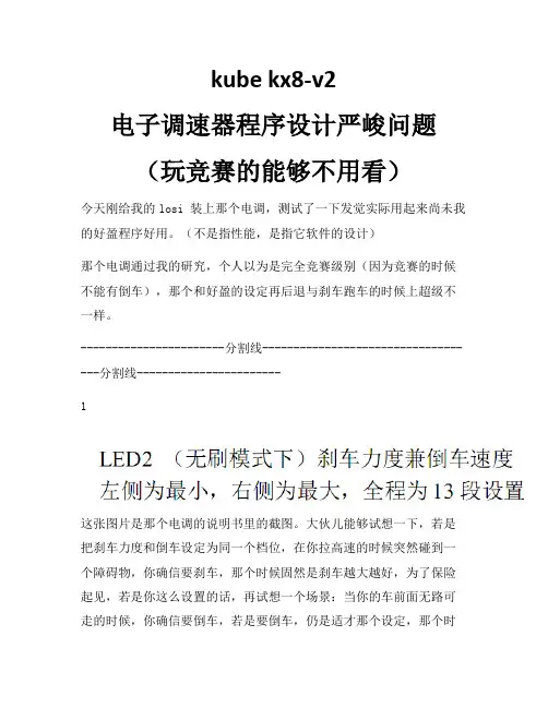
-----------------------分割线-----------------------------------分割线-----------------------1这张图片是那个电调的说明书里的截图。
大伙儿能够试想一下,若是把刹车力度和倒车设定为同一个档位,在你拉高速的时候突然碰到一个障碍物,你确信要刹车,那个时候固然是刹车越大越好,为了保险起见,若是你这么设置的话,再试想一个场景:当你的车前面无路可走的时候,你确信要倒车,若是要倒车,仍是适才那个设定,那个时候倒车力度就会超级大以至于你都操纵不了(不明白我是不是用好盈电挪用太久的缘故),因为遥控器倒车的扳机行程比前进的扳机行程短,因此若是突然扣动扳机的话,后扳机的行程确信是不行操纵的,因此又有可能会撞到别的物体致使爱车损坏。
2这张图片也是电调说明书里面的截图。
大伙儿看着这张截图再试想一下:若是你想倒车,你就会设置第2或第3,当你拉高速突然发觉有物体显现的时候,你就要刹车,若是你的刹车力度不够,正常情形下用好盈的人都明白再向后推扳机就会转变成倒车,如此就可不能撞到那个突然显现的物体.可是那个电调,若是你想这么做,你确信可不能选择第1条和第3条,那么就只有第2条能够选择.若是你选择了第2条,那么当你平常适应性刹车的时候,电机遇直接反转,如此的话会对齿轮再平常情形下损害超级大,因为结合我说的第1条,刹车力度你设置小的话会直接立刻停下然后倒车,若是设置大的话又会迅速倒车致使齿轮严峻损坏,如此的话不管你怎么设置,都不能达到理想成效。
-----------------------分割线-----------------------------------分割线-----------------------因此我最后总结为,若是你用那个电调,最好取消倒车选项。

▸▸Eight channels in 2U –▸Extremely▸high▸channel▸density▸reduces▸space▸requirements▸and▸installation▸time▸▸High continuous output power of 250 W per channelat 70 V, 4 ohms, 8 ohms, and 16 ohms*▸▸All channels individually selectable for lo-Z or hi-Z Loudspeakers▸(2▸ohm▸–▸16▸ohm)▸and▸distributed▸systems▸can▸be▸connected▸to▸the▸same▸unit▸▸Bridged operation – Channel▸pairs▸bridgeable▸for▸increased▸output▸or▸for▸driving▸100▸V▸systems▸▸▸Patented output stage based on Class D topology▸▸High efficiency for lower thermal stress ▸▸General Purpose Input/Output (GPIO) – Compatible▸with▸third-party▸control▸systems▸▸NomadLink® network ready▸▸Universal Power Factor Corrected PSU with IEC inlet▸▸Efficient cooling – Dual▸variable▸speed,▸intelligent▸fans▸and▸parallel▸airflow▸over▸output▸devices▸provide▸uniform▸cooling ▸▸Comprehensive circuit protection and fault indication ▸▸Phoenix-style input connectors and barrier strip output connectorsAn Installation Amplifier without CompromiseLab.gruppen▸amplifiers▸have▸earned▸an▸enviable▸worldwide▸reputa-tion▸for▸sonic▸excellence▸and▸rock-solid▸durability▸in▸touring▸sound▸applications.▸These▸same▸qualities▸are▸now▸available▸for▸a▸broad▸range▸of▸installed▸sound▸applications▸in▸the▸C▸20:8X▸amplifier.▸By▸offering▸an▸unmatched▸combination▸of▸channel▸density,▸operating▸ef-ficiency▸and▸configuration▸flexibility,▸the▸C▸20:8X▸presents▸convincing▸performance▸and▸cost-saving▸advantages.▸Applications▸include▸pri-mary▸systems▸for▸theme▸parks,▸shopping▸malls,▸airports,▸hotels▸and▸▸restaurants▸as▸well▸as▸auxiliary▸systems▸for▸performance▸venues,▸houses▸of▸worship▸and▸numerous▸other▸installed▸sound▸applications. To▸achieve▸higher▸channel▸density▸without▸compromising▸per-formance,▸Lab.gruppen▸engineers▸developed▸a▸new▸output▸stage▸design.▸Based▸on▸a▸patented▸Class▸D▸circuit▸topology,▸these▸output▸stages▸produce▸sustained▸high▸power▸levels▸with▸very▸low▸distortion▸while▸maintaining▸efficiency▸levels▸of▸near▸90%.▸A▸new▸universal▸switching▸power▸supply▸employs▸Power▸Factor▸Correction▸(PFC)▸▸to▸stabilize▸current▸draw,▸and▸it▸accepts▸any▸mains▸voltage▸from▸▸65▸–▸265▸V▸(+/-▸10%)▸@▸50▸Hz▸or▸60▸Hz▸through▸the▸appropriate▸▸IEC▸cord.The▸C▸20:8X▸includes▸unique▸features▸which▸enable▸each▸unit▸–▸or▸even▸each▸channel▸–▸to▸be▸configured▸for▸a▸specific▸application▸or▸load▸condition.▸Input▸gain▸is▸selectable▸in▸four-channel▸groups,▸and▸a▸35▸Hz▸high▸pass▸filter▸may▸be▸inserted.▸All▸channels▸are▸bridgeable▸in▸pairs,▸and▸Lab.gruppen’s▸exclusive▸Voltage▸Peak▸Limiter▸(VPL)▸fea-ture▸allows▸each▸channel▸to▸be▸individually▸optimized▸for▸the▸reactive▸characteristics▸of▸the▸connected▸load.For▸comprehensive▸remote▸monitoring▸and▸control,▸the▸C▸20:8X▸includes▸NomadLink®▸network▸ports▸for▸connecting▸to▸an▸optional▸NLB▸60E▸NomadLink®▸Bridge▸&▸Network▸Controller▸and▸an▸Ethernet-linked▸PC.▸With▸NomadLink®,▸key▸amplifier▸parameters▸are▸displayed▸via▸DeviceControl▸software,▸and▸remote▸control▸of▸channel▸mute▸and▸power▸on/off▸is▸under▸network▸control.▸Alternatively,▸the▸GPIO▸▸facilities▸allow▸access▸to▸key▸amplifier▸functions▸via▸third-party▸▸remote▸control▸systems.▸To▸ensure▸a▸long▸and▸trouble-free▸service▸life,▸the▸C▸20:8X▸▸incorporates▸extensive▸features▸to▸safeguard▸internal▸circuits▸and▸connected▸loads.▸Protection▸and▸warning▸circuits▸prevent▸damage▸or▸service▸interruptions▸due▸to▸excessive▸current,▸DC▸at▸output,▸▸over-temperature,▸non-musical▸VHF▸(very▸high▸frequencies),▸and▸open▸load▸conditions.▸In▸addition,▸soft-start▸and▸PSU▸current▸limit-ing▸protect▸the▸mains▸supply▸from▸interruptions▸due▸to▸tripped▸circuit▸breakers▸or▸blown▸mains▸fuses.*▸Maximum▸continuous▸output▸power,▸all▸channels▸▸▸▸▸▸driven,▸VPL▸set▸at▸100▸V▸and▸Gain▸set▸at▸32▸dB ▸Auditoriums▸Performing Arts Centers▸Convention Centers▸Stadiums and Arenas▸Theme Parks▸Hotels▸Houses of Worship▸Restaurants▸Clubs▸Educational Establishments▸Boardrooms▸Museums▸Offices▸Shopping Malls▸Transportation Facilities ApplicationsC 20:8XItem no. TDS-C208X_V6GeneralNumber▸of▸channels8Peak▸total▸output▸all▸channels▸driven 2000▸WPeak▸output▸voltage▸per▸channel 100▸V▸/▸70▸Vrms Max.▸output▸current▸per▸channel 8▸Arms Max. Output Power 16 ohms 8 ohms 4 ohms 2 ohms Hi-ZPer▸ch.▸(all▸ch.’s▸driven)250▸W 250▸W 250▸W 125▸W 250▸W▸(70▸Vrms▸/▸100▸V▸peak)Bridged▸per▸ch.500▸W500▸W250▸Wn.r.500▸W▸(140▸Vrms▸/▸200▸V▸peak)Performance with Gain: 32 dB and VPL: 100 V THD▸20▸Hz▸-▸20▸kHz▸for▸1▸W<0.1%THD▸at▸1▸kHz▸and▸1▸dB▸below▸clipping <0.05%Signal▸To▸Noise▸Ratio>112▸dBA Channel▸separation▸(Crosstalk)▸at▸1▸kHz>70▸dBFrequency▸response▸(1▸W▸into▸8▸ohms)▸+0/-3▸dB 6.8▸Hz▸-▸34▸kHz Input▸impedance20▸kOhm Input▸Common▸Mode▸Rejection,▸CMR 50▸dB Output▸impedance▸@▸100▸Hz48▸mOhmVoltage Peak Limiter (VPL), max. peak output VPL,▸selectable▸per▸ch.▸(V)▸3)100,▸63,▸45,▸32▸V VPL,▸selectable▸when▸bridged▸(V)▸3)▸1)200,▸126,▸90,▸64▸V Voltage▸Peak▸Limiter▸mode▸(per▸ch.)Hard▸/▸SoftGain and LevelAmplifier▸gain▸selectable▸(all▸channels)▸1)▸–▸rear-panel▸switches 29,▸32,▸35,▸38▸dBDefault▸gain32▸dBLevel▸adjustment▸(per▸ch.)Front-panel▸potentiometer,▸21▸position▸detented▸from▸-inf▸to▸0▸dB,▸hidden▸behind▸security▸panel/dust▸filter▸grilleConnectors and switches Input▸connectors▸(per▸ch.)3-pin▸Phoenix,▸electronically▸balanced Output▸connectors▸(per▸ch.)Barrier▸strip▸2-pole▸screw▸terminals Output▸bridge▸mode A+B,▸C+D,▸E+F ,▸G+H,▸inputs▸A,▸C,▸E,▸G▸are▸signal▸source High▸pass▸filterFixed▸at▸35▸Hz,▸switchable▸per▸channelNomadLink ®▸network On▸board,▸2▸x▸RJ45▸connectors,▸IN▸and▸OUT Intelligent▸fans▸(on/off)Y es,▸depending▸on▸presence▸of▸output▸signal Power▸on/off▸and▸Remote▸enable▸on/off Individual▸switches▸on▸front-panelCoolingTwo▸fans,▸front-to-rear▸airflow,▸temperature▸controlled▸speed General▸Purpose▸Outputs▸(GPO)Contact▸Closure▸types,▸2-pole▸Phoenix General▸Purpose▸Inputs▸(GPI)Contact▸Closure▸types,▸2-pole▸PhoenixFront-panel indicators Common NomadLink ®▸Network;▸Power▸Average▸Limiter▸(PAL)▸2);▸Power▸on▸Per▸channelSignal▸present▸/▸High-impedance;▸Voltage▸Peak▸Limiter▸(VPL);▸Current▸Peak▸Limiter▸(CPL):▸Very▸High▸Frequency▸(VHF);▸High▸temperature;▸Fault;▸MutePowerOperating▸voltage,▸230▸V▸/▸115▸V▸nominal 65-265▸V Minimum▸power-up▸voltage,▸230▸V▸/▸115▸V 80▸V Power▸Average▸Limiter▸(PAL)▸2)YesSoft▸start▸/▸Inrush▸current▸draw Yes▸/▸max.▸5▸A Mains▸connector IEC▸InletDimensions (W/H/D)W:▸483▸mm▸(19”),▸H:▸88▸mm▸(2▸U),▸D:▸343▸mm▸(13.5”)Weight 8.5▸kg▸(18.75▸lbs.)FinishBlack▸painted▸steel▸chassis▸with▸gray▸painted▸steel▸front ApprovalsCE,▸ANSI/UL▸60065▸(ETL),▸CSA▸C22.2▸NO.▸60065,▸FCC▸▸Note 1):▸Automatic▸-6▸dB▸gain▸compensation▸when▸bridging▸channels.▸Ch.’s▸A+B▸and/or▸C+D,▸E+F,▸G+H,▸can▸be▸bridged▸individually.▸Note 2):▸PAL▸can▸reduce▸the▸maximum▸output▸power▸to▸keep▸the▸power▸supply▸operating▸safely,▸and/or▸to▸prevent▸excessive▸current▸draw▸tripping▸the▸mains▸breaker.▸▸▸▸▸Refer▸to▸Operation▸Manual.▸Note 3):▸For▸sine▸waves,▸peak▸voltage▸output▸values▸translate▸to▸Vrms▸with▸the▸formula▸V/1.41▸=▸Vrms.▸E.g.▸100▸V▸peak▸equals▸app.▸70▸Vrms.▸▸Hence,▸outputs▸can▸be▸set▸for▸high-impedance▸loads▸without▸requiring▸a▸transformer. All specifications are subject to change without notice.L a b .g r u p p e n a b ▸ S w e d e ni n t e r n a t i o n a L c o n t a c t ▸ i n f o @L a b g r u p p e n .c o m | u S & c a n a d a c o n t a c t ▸ i n f o @t c g -a m e r i c a S .c o mw w w .l a b g r u p p e n .c o mSpecifications C 20:8X。

一、概述:1.1主要用途:ZYK—8型智能有载开关控制器(以下简称控制器)是和有载分接开关配套使用,采用手动或自动工作方式来控制有载分接开关进行分接变换,以实现变压器的输出电压稳定在所要求的精度范围内。
1.2 主要性能特点(1)含有手动、自动两种工作方式。
(2)对有载分接开关的极限分接位置进行限位。
(3)升、降换位时采用脉冲触发电路,并具有升、降自锁、互锁功能。
(4)具有过压报警功能。
(5)采用数码管显示采样电压值和有载分接开关所处的现行档位。
(6)控制器可实现输出一一对应分接位置信号以及远控信号输(无源接点),实现有载分接开关通过触点的远端的监视和控制。
(7)控制器可输出BCD码分接位置信号。
(普通控制器不带此接口,也不带相应的配件,用户如需要可在合同上特别注明)(8)在自动工作方式时,当由于某种原因失去采样电压时,控制器能使有载分接开关自动回到规定档位。
(只有ZYK-8具有此功能)上述功能全部采用数字集成电路来完成,并选用进口芯片,控制器具有性能稳定、工作可靠、抗干扰能力强、使用寿命长、操作简便等优点。
二、使用环境:1、控制器必须安装于室内;2、使用环境温度:-10℃―+40℃;3、环境相对湿度:<85%;4、海拔高度不高于 2000米;5、仪器避免振动和冲击;6、环境周围不含腐蚀气体或导电尘埃。
三、主要技术参数及指标:1、工作电源电压: AC 380V 50H Z2、基准整定电压: AC 100V 或400V 50H Z3、控制电压灵敏度:± 2.5% (或按合同要求)4、控制电压误差:± 1%5、自动调压延迟时间 15∽60秒、出厂时调至30± 5秒6、过压报警值:>基准采样电压的10%7、自动回中档(或按合同要求)8、外型尺寸: 290x210x95mm39、重量: 4.5kg四、结构及工作原理图:(参考电路原理方框图)1、结构控制器采用金属外壳,外型轻巧美观大方。

tk8的用法1. 什么是tk8tk8是一个用于管理和部署Kubernetes集群的工具。
它是基于Terraform和Kubernetes的开源工具,旨在简化集群的创建、配置和管理过程。
2. tk8的特点2.1 简化集群创建使用tk8可以快速创建一个全新的Kubernetes集群。
tk8提供了一套易于使用的命令行工具,通过简单的配置文件即可创建一个完整的集群环境。
tk8还支持自动化的网络配置和节点初始化过程,大大减少了集群创建的工作量。
2.2 灵活的配置选项tk8提供了丰富的配置选项,可以根据实际需求灵活配置集群的规模、网络、存储等参数。
可以通过配置文件或命令行参数来指定这些选项,满足不同场景下的需求。
2.3 自动化的部署过程tk8可以自动化地部署Kubernetes集群的各个组件,包括Master节点、Worker节点、网络插件、存储插件等。
tk8会自动下载和安装所需的软件包,并进行必要的配置和初始化工作。
用户只需简单地执行几个命令,就可以完成整个部署过程。
2.4 高可用性和容错性tk8支持创建高可用的Kubernetes集群。
它可以自动创建多个Master节点,并将它们配置为高可用模式。
在节点故障或网络中断的情况下,tk8可以自动恢复集群的正常运行。
2.5 扩展性和可维护性tk8提供了一套灵活的插件机制,可以方便地扩展集群的功能和服务。
用户可以根据需要选择和安装不同的插件,满足特定的需求。
同时,tk8还提供了一套简洁的命令行接口和日志记录功能,方便用户进行集群的管理和维护工作。
3. tk8的安装和配置3.1 安装要安装tk8,首先需要安装Terraform和Kubernetes。
可以根据官方文档提供的步骤进行安装。
3.2 配置配置tk8需要创建一个配置文件,可以使用YAML或JSON格式。
配置文件包含了集群的各种参数和选项,如集群规模、网络配置、存储配置等。
可以根据实际需求修改配置文件中的参数值。
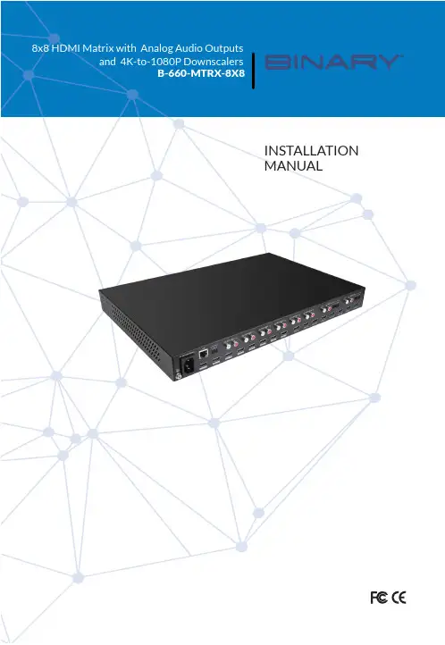
To reduce the risk of fire or electric shock, read and follow all instructions and warnings in this manual. Keep this manual for future reference.1. Do not expose this apparatus to rain or moisture. Do not expose this equipment to drippingor splashing, and ensure that no objects filled with liquids, such as vases, are placed on the equipment. Do not use this apparatus near water.2. Do not remove cover. No user serviceable parts inside.3. Clean only with a dry cloth.4. Do not block any ventilation openings. Install according to manufacturer’s instructions.5. Do not install near any heat sources such as radiators, heat registers, stoves or otherapparatus (including amplifiers) that produce heat.6. Do not override the safety purpose of the polarized or grounding plug. A polarized plug hastwo blades, one of which is wider than the other. A grounding plug has two matching blades and a third grounding prong. The wide blade or the third prong is provided for your safety. If the provided plug does not fit into your outlet, consult an electrician for replacement of the obsolete outlet.7. Protect the power cord from being walked on or pinched, particularly at the plug end andwhere the power cord is attached to the apparatus.8. Only use attachments and accessories specified by the manufacturer.9. Refer all servicing to qualified service personnel. Servicing is required when the apparatushas been damaged in any way, such as when the power supply cord or plug is damaged, liquid has been spilled on or objects have fallen into the apparatus, the apparatus hasbeen exposed to rain or moisture, the apparatus does not operate normally, or it has been dropped.10. To completely disconnect this equipment from power, disconnect the power supply cordfrom the power outlet.The lightning flash with arrowhead symbol, within an equilateral triangle, is intended to alert the user to the presence of uninsulated dangerous voltage within the product’s enclosure that may be of sufficient magnitude to constitute a risk of electric shock to persons.The exclamation point within an equilateral triangle is intended to alert the user to the presence of important operating and maintenance (servicing) instructions in the literature accompanying the appliance.2This equipment has been tested and found to comply with the limits for a Class B digital device, pursuant to Part 15 of the FCC Rules. These limits are designed to provide reasonable protection against harmful interference in a residential installation. This equipment generates uses and can radiate radio frequency energy and, if not installed and used in accordance with the instructions, may cause harmful interference to radio communications. However, thereis no guarantee that interference will not occur in a particular installation. If this equipment does cause harmful interference to radio or television reception, which can be determined by turning the equipment off and on, the user is encouraged to try to correct the interference by one or more of the following measures:• Reorient or relocate the receiving antenna.• Increase the separation between the equipment and receiver.• Connect the equipment into an outlet on a circuit different from that to which the receiver is connected.• Consult the dealer or an experienced radio/TV technician for help.Changes or modifications not expressly approved by the party responsible for compliance could void the user’s authority to operate the equipment.31. Product Overview (5)2. Features (5)3. Package Contents (5)4. Device Layout (6)4.1. B-660-MTRX-8x8 Front Panel (6)4.2. B-660-MTRX-8x8 Rear Panel (6)5. Installation & Wiring (7)5.1. Installation (7)5.2. Wiring (7)6. RS232 Control (8)7. IR Remote Control (9)8. Web UI Control (9)8.1. Get Access to the Web UI (9)8.2. Web UI Introduction (10)9. Specifications (18)9.1. Transmission Distance (19)10. Warranty (19)11. Support (19)41.B-660-MTRX-8x8 is an 8x8 HDMI 2.0 Matrix with resolutions supported up to 4K@60Hz 4:4:4 8bit and HDCP 2.2 compatibility. It allows eight sources to be switched to eight HDMI displays simultaneously. The B-660-MTRX-8x8 supports various HDR formats including HDR10, HLG and Dolby Vision up to 4K60, and ARC for residential applications. It also allows for flexible video output in mixed 1080P and 4K TV environments, by providing 4K-to-1080P simple downscaler with each HDMI output. B-660-MTRX-4x4 Matrix can be controlled by IR, RS232 and LAN control with Telnet API and Web UI.Designed for 1U rack mount and stand-alone installation, this matrix offers an Ultra HD A/V switching and distribution solution ideal for a variety of applications, such as offices, schools, conference rooms, hotels, etc. .2.• Includes 8 HDMI inputs and 8 HDMI outputs.• Inputs and outputs support video resolutions up to 4K@60Hz 4:4:4 8bit and HDCP 2.2. • Supports 4K@60Hz HDR formats, including HDR10, HLG & Dolby Vision.• Fast switching among multiple video sources.• Provides independent 4K-to-1080P simple downscaler with each HDMI output.• Provides rich audio output modes:>Supports HDMI de-embedded audio from associated HDMI output.>Supports ARC audio return via associated HDMI output(in this case the HDMI output must be connected to TV’s HDMI ARC port).• Provides ready-to-use RCA analog ports for all audio outputs and 5-pin true differentialbalanced audio ports for audio outputs 7&8.• Supports IR, RS232 and LAN (Telnet API & Web UI) control options.• OvrC enabled.3.• 1 x B-660-MTRX-8x8 Matrix• 1 x AC Power Cord with US Pins• 1 x IR Remote• 2 x Phoenix Connectors (3.5mm, 5 Pins)• 1 x Phoenix Connector (3.5mm, 3 Pins)• 2 x Mounting Brackets (with Screws)• 1 x Installation Manual54.4.1. B-660-MTRX-8x8 Front Panel1. Output Channel IndicatorIndicates input for output port 1-8.2. IR WindowReceives signals from IR remote.3. STATUS LEDOn: The device is connected to the network.Off: No network is connected to the device.4. Power SwitchPress to power on/off the matrix.4.2. B-660-MTRX-8x8 Rear Panel1. HDMI IN (1-8)Connect to HDMI Sources.2. HDMI OUT (1-8)Connect to HDMI displays.3. AC 100-240V 50/60HzConnect the power cord provided. Accepts AC power of 100-240V 50/60Hz.4. LANConnect to a control system for Web UI or Telnet control.5. RS-232Connect to a control PC or control system for RS232 serial control.6. AUDIO OUT 1-8L/R analog output (1-8): L/R analog audio output. Connect to audio devices via RCA stereo6audio cables;Phoenix Connector Audio output (7-8): 5 pins, 3.5mm phoenix connector. Connect to audio devices via 5pins, 3.5mm phoenix stereo audio cables.Note: Audio output ports can be set through web UI or API commands to output HDMIde-embedded audio, or ARC audio from associated HDMI output connected TVs (with ARC function supported, and the CEC function is set to on)5.5.1. InstallationB-660-MTRX-8x8 occupies 1U space and can be placed on a solid and stable surface or installed on a standard equipment rack.Steps to install the matrix on an equipment rack:1. Attach the installation bracket to the enclosure using the screws provided in the packageseparately.The bracket is attached to the enclosure as shown.2.3. Repeat steps 1-2 for the other side of the unit.4. Mount and affix the unit in the rack mount with the mounting screws.5.2. WiringWarnings:• Before wiring, disconnect the power from all devices.• During wiring, connect and disconnect the cables gently.Steps for device wiring:1. Connect HDMI INConnect the HDMI sources (such as PC, Blu-ray player, Apple TV, 4K media player, etc) to the HDMI IN 1-8 of the Matrix.72. Connect HDMI OUTConnect HDMI display device (such as TV, projector, LED/LCD display) to the HDMI OUT 1-8.3. Connect AUDIO OUTConnect audio devices to AUDIO OUT 1-8 of the Matrix (e.g. audio amplifier).4. Connect for additional control options:• LAN Control (Telnet/Web UI): Connect a Local Area Network to the LAN port of the Matrix.• RS232 Control: Connect a control PC or control system to RS-232 port of the Matrix.• IR Control: The IR Remote provided is for controlling the Matrix through IR signal.5. Connect the AC power cord provided to the Matrix.6. Power on all attached devices.Application Diagram6.Advanced users may need to control the matrix through RS232 serial communication. Connect a control PC or control system to the RS-232 port of the receiver. API command for RS232 control is available in the separate document “API Command Set_ B-660-MTRX-8x8”. A professional RS232 serial interface software (e.g. Serial Assist) may be needed as well.Before executing the API command through RS232 serial connection, please ensure RS232 interface of the device and the control PC are configured correctly.897.The Matrix can be controlled by the IR Remote provided. Point the Remote directly to the IR window on front panel of the Matrix. Now you can select input source for each output display.Next InputPrevious InputOutput 2To select input source for output display:1. Locate the target output you want to switch inputs for, numbered 1-8 vertically along the right side.2. Press the previous ( ) or next ( ) button to select the desired input source.A complete list of hex IR codes can be found in the “B-660-MTRX-8x8_IR Code” file.8.The Web UI designed for the matrix is available for basic controls and advanced settings of the device. The Web UI can be accessed through a browser, e.g. Chrome, Firefox, Safari, Opera, IE, etc..The default network mode of matrix is DHCP , in this mode, if there’s not a DHCP server, the matrix supports for a local 169.254.xxx.xxx IP address.8.1. Get Access to the Web UI1. Connect the LAN port of the matrix to your PC using a straight UTP cable, or connect the matrix to a local area network, and connect your PC to the same network. Using the later connection, ensure a DHCP server is included in the local area network.102. Use a tool such as OvrC to search the IP address of the device or send API command to get IP address (More information, see the separate document “API Command Set_B-660-MTRX-8x8”). Set your PC to the same network segment as the matrix if you connect the matrix to your PC directly.3.Input the IP address in your browser and press Enter. The following window will display.Enter the Username and Password. The default username and password are both “binary”. Then click “Login”. When login firstly, the following page will be popped up to remind you tochange the username and password.Note:• The changed username and password must be different from the default username and password.• Username and Password must be 4 to 16 characters in length, alphanumeric only.8.2. Web UI IntroductionThe web UI page includes the following submenus: SIGN OUT, FACTORY DEFAULT, UPDATE and REBOOT on the up-right corner, Matrix Control, Log and System in the main page.8.2.1.SIGN OUTClick the icon to return to the login page.8.2.2.FACTORY DEFAULTClick the icon, the following window will be popped up, click “CONFIRM” to reset the device tofactory default.UPDATE8.2.3.Click the icon, enter the following window.1112Click “BROWSE” to select the needed upgrade file (“.zip” file is need, you can upload ARM,MCU, or web UI upgrade file), and then click “UPDATE” to upgrade the corresponding firmware.Note: Do not power off the device when upgrading.8.2.4.REBOOTClick the icon, the follwing window will be popped up, click “CONFIRM” to reboot the device.Note: Please wait at least 2 minutes to refresh the web page and log in again.8.2.5. Matrix ControlMove the mouse to “Matrix Control” in the web page, it shows the following sub-menus: Switch and preset, Configuration and Display control. Click the item you want to configure.1. Switch and preseta. Video ControlThis section manages distribution of input video sources to output displays. Click the button in the table to select the input for the output display (button turns from white to blue once selection is done).13• All Outputs: Click to route one input to all outputs.• None: None input is routed to the output (or the output is turned off).By default, Video Input 1 routes to Output 1, …, Video Input 7 routes to Output 7, Video Input 8 routes to Output 8.b. Audio ControlThis section allows you to select audio source for each audio output.• HDMI de-embed: AUDIO OUT port outputs De-embedded audio from the corresponding HDMI OUT port.• HDMI ARC: AUDIO OUT port outputs ARC audio from the corresponding HDMI OUT port.The default setting for each audio output is HDMI de-embed.c. PresetsThis section saves/loads the input/output switch settings to or from the Matrix.• SAVE: Settings in Video Matrix Control section are saved.• LOAD: Preset already saved is loaded.142. ConfigurationThis section allows you to change name for each input and output, set EDID for each input, andshow video and audio informations for each inputs and outputs.• Input/Output: Select one input/output to set and show its video and audio informations.• Input Name/Output Name: Redefine the input/output names.For Input:• EDID: Click to select the EDID for input.>Apply: Click to make the EDID setting take effect. >ExportEDID: Click to save the EDID information of the selected input port as a bin fileto local PC.• Video In/Audio In: Show the video and audio informations for selected inputs.15For Output:• ExportEDID: Click to save the EDID information of the TV connected to the selected output port as a bin file to local PC.• Video Out/Audio Out: Show the video and audio informations for selected outputs.3.Display Control• Display On: Click to send the saved Display On command to the connected CEC-enabled display to power on it immediately.• Display Off: Click to send the saved Display Off command to the connected CEC-enabled display to power off it immediately.• Auto On/Off: Click to enable or disable the CEC Auto Control. By default, the auto CEC control is on.• Delay Time (1~30min): Click the up/down arrow to set the time for the display to power off automatically when no signal is present. For example, if Auto control is set as on and the time is set to 2 minutes, the output display will power off automatically when there’s no signal at the display for 2 minutes.8.2.6. Log1. API TestThis section allows you to input API commands to control the matrix.• Send: Click to send the command entered to the matrix.Note:• More API commands, please refer to the separate document “API Command Set_B-660-MTRX-8x8”.16•The return information of the sent command will be shown in log box:2. LogThis section shows the operation log and return information of the tested command.• Export Log: Click to export omni log recording information for remote trouble shooting.8.2.7. SystemMove the mouse to “System” in the page, it shows the following sub-menus: Information, Network and Other. Click the item you want to configure.1. InformationThis section shows the basic information of the matrix, including MODEL, SERVICE NUMBER,SERVICE TAG, MAC ADDRESS, IP ADDRESS and FIRMWARE VERSION.2. NetworkNetwork is used to set between the static and dynamic IP address.17• DHCP: When enabled, the IP address of the Matrix is assigned automatically by the DHCP server connected.• Static: When enabled, set up the IP address manually.• Apply: Click to enable the network setting.Note:• When “Static” is selected, please ensure your PC is in the same network segment as the Matrix, i.e. the IP address of your PC should be set as 192.168.xxx.xxx.• Please wait for 2-3 minutes for the Matrix’s LAN module to reboot and reconnect after the network setting is changed.By default, the IP type is set as DHCP . If it doesn’t have DHCP server, the matrix supports for local IP address. Use API Command to get the IP address.3.Othera. Power Saving ModeThis section allows you to set power saving mode of the matrix to on/off. The default setting isoff.Note: When set Power Saving Mode to on, the matrix will enter standby mode to use lesspower than normal operation mode. In this mode, the front panel display will be off, and outputs will the powered down.18b. Login UsernameThis section is where to change the Username.• Apply: Click to make the setting take effect.Note: User name must be 4 to 16 characters in length, alphanumeric only.c. Login PasswordThis section is where to change Password.• Apply: Click to make the setting take effect.Note: Password must be 4 to 16 characters in length, alphanumeric only.9.199.1.Transmission Distance10. WARRANTY2-Year Limited WarrantyThis Binary product has a 2-Year limited warranty. This warranty includes parts and labor repairs on all components found to be defective in material or workmanship under normal conditions of use. This warranty shall not apply to products that have been abused, modified or disassembled. Products to be repaired under this warranty must be returned to SnapOne or a designated service center with prior notification and an assigned return authorization number (RA).11. SUPPORTNeed Help? Contact Tech Support!If you need further clarification, please call tech support at (866) 838-5052, or email ***********************. For other information, instructional videos, supportdocumentation, or ideas, visit our website and view your item’s product page at .Rev: 220418-160923© 2022 Binary。

Powering different pedal typesEach individual rig is different, therefore if you have questions about using the CIOKS 8 power supply please e-mail your detailed questions including the power requirements of your specific pedals directly to .Not included accessoriesCIOKS GRIPThe GRIP bracket allows easy and drill-free mounting of CIOKS 8 power supply below any Pedaltrain board except the smallest Nano model (order no. GRIP).Hex stand-offsA set of four 8mm hex stand-offs (only 3 need to be used) to make an offset and space for the finger screws in-between the power supply and a Templeboard (order no. 4HEX).Technical specificationsInput/link 1-2: 24V DC, max. 4AOutputs 1-8: 9V DC / 660mA or12V DC / 500mA or15V DC / 400mA or18V DC / 330mA eachTotal output power is max. 48W provided an appropriate and sufficient input power source is applied. Size: 120x88x25,4mm / 4.7x3.5x1.0” (excl. rubber feet)Weight: 340g / 0.75 lbWarranty period: 5 years worldwideWhat’s in the box?•CIOKS 8 power supply•12 Flex cables•50cm DC Link cable (to connect to CIOKS DC7)•Mounting hardware (2 screws and a hex-key)•Product sheet (drill guide)•Flex and DC Link cable selection guide•Sticker (sheet with 2pcs.)•ManualUser’s ManualVersion 1.02 – April 2020IntroductionSince 1991, the Danish company CIOKS has been providing guitar and bass players with reliable power supplies dedicated for effect pedals. The CIOKS 8 power supply is part of our Future Power Generation range of professional power supplies. CIOKS 8 has 8 isolated outlets for powering pedals and offers 4 different output voltages on each outlet. Our new CIOKS 8 power supply is recommended to use to extensively expand your existing DC7 power supply with additional 8 isolated outlets.Features•Expand your CIOKS DC7 power supply with 8 additional isolated outlets•CIOKS 8 offers a compact one-inch profile (25,4mm)•Low weight, 340g (0.75 lb)•Ultra-low noise achieved by multi-stage filtering•8 isolated DC-outlets, 6W each, 660mA @ 9V• 4 selectable voltages on each outlet (9, 12, 15 or 18V)•Individual status LED on each outlet and a global status LED•Power it with CIOKS DC7 or another strong 24V DC source•Total maximum output power 48W•Mounting hardware for Pedaltrain and Temple Audio boards is included•Compatible with CIOKS GRIP, for drill-free Pedaltrain mounting•12 Flex cables included•Designed in Denmark, assembled in Poland•5-year worldwide warrantyOverviewLeft and rightOn the left side you will find the two input/link DC sockets and the three RCA sockets being outlets 1-3 for powering pedals. On the right there are five RCA sockets being outlets 4-8 also for powering pedals.TopCIOKS logo has a red LED placed in the middle of the letter ‘O’ and this functions as a global status indicator. For each outlet you have a voltage selector switch and an advanced LED indicator.FrontThe two holes in the front with metric M4 threads are to be used with the GRIP bracket (sold separately) for mounting to Pedaltrain boards with no drilling required.BottomThe four detachable rubber feet are situated on the bottom of the enclosure. On this same surface you will find 3 holes with metric M4 threads which can be used for mounting of the power supply to a pedalboard. Getting startedConnect a 24V DC supply voltage to CIOKS 8 power supply from either CIOKS DC7 or other compatible source. Set the output voltage on a given outlet to either 9, 12, 15 or 18V depending on the needs of the particular pedal to be powered. Using the right Flex cable type connect your pedal to this outlet. Repeat this with your remaining pedals.Advanced LED Monitoring featureEach isolated outlet has its individual LED status indicator. The indicator is lit in normal operation. The LED light gets dim when you operate just on the edge of the power limit, regardless of which voltage you have selected on the outlet. If you overload or short circuit an outlet, the respective LED indicator turns off. The light intensity of the status LED will be higher when the output voltage is set to a higher value than 9V being 12, 15 or 18V.Global status indicatorIf the CIOKS 8 power supply is powered from a power source with an output power capability exceeding 56W the red LED inside the O letter in CIOKS logo will be lit regardless of pedal load. If the power source supplying CIOKS 8 has a power capability of less the 56W the input voltage will when reaching the adapter’s maximum power capability start to sag hence turning the CIOKS 8 global status indicator off. Pedalboard mountingGeneralThe most solid way is using the drill template being the product sheet and then drill two diagonally positioned ø4,5mm or ø5,0mm holes in the pedalboard and fasten CIOKS 8 to it with the two included screws. Due to CIOKS 8 extremely flat profile and low weight you can use Dual-Lock tape or industrial Velcro to fasten it below any type of pedalboard. In general for mounting in a rack, pedalboard or other structure we recommend using two of the five threaded M4 holes (3 in the bottom and 2 in the front) and matching metric M4 screws. Remember not to penetrate the CIOKS 8 by more than 5mm with the screws used.PedaltrainFor Pedaltrain boards we recommend an easy alternative way of mounting the CIOKS 8 unit by using the GRIP bracket where no drilling is needed. Temple AudioThe three threaded M4 holes in the bottom of CIOKS 8 are aligned with the grid of Templeboards and allow for very easy mounting on top or below any Temple Audio pedalboard with the included 2 screws. We recommend using the two holes positioned diagonally. If you want to make a distance between the board’s surface and the CIOKS 8 to allow space for the Temple Audio finger screws you should get a set of three 8mm hex stand-offs with matching screws (order no. 4HEX) and then use these with all three threaded holes in the bottom of the power supply.Included accessoriesFlex cablesCIOKS offers a wide selection of different Flex cable types for connection your pedals to the power supply. Below you see a list of the included Flex cables with your unit:•Standard Flex type 1 – black with 5,5/2,1mm centre negative DC plug x7 •Standard Flex type 2 – red with 5,5/2,1mm centre positive DC plug x1 •Standard Flex type 4 – green with 5,5/2,5mm centre positive DC plug x1 •Standard Flex type 5 – black with tip positive 3,5mm Jack plug x1 •Split Flex type 1 – black with two 5,5/2,1mm centre negative DC plugs x1 •3-way daisy chain Flex type 1 – black with three 5,5/2,1mm centre negative DC plugs x1 Split Flex should be used if you would like to power two pedals with the same voltage using only one outlet. In the same manner you should use the 3-way daisy chain if you wish to power three pedals of one outlet. For further information about Flex cables please have a look at the included Flex cable selection guide or visit CIOKS web site.DC Link cableA DC Link cable in 50cm length is included and should be used to connect CIOKS 8 power supply to CIOKS DC7 power supply’s 24V DC outlet. You can also use this cable to connect and power CIOKS 8 of another compatible 24V DC source.Mounting hardwareWe have included all the needed mounting hardware to mount the power supply on top or underneath a Pedaltrain or a Temple Audio pedalboard. You can of course also attach it to other types of pedalboards. CIOKS 8 output power capabilityWhen CIOKS 8 is powered of the 24V DC outlet on CIOKS DC7 power supply which we recommend you’ll have a total of 42W for powering pedals of the 15 outlets. There’ll be no difference in output power per outlet whether you use an outlet on CIOKS 8 or the DC7 as they will be sharing the same source. You can also power your CIOKS 8 power supply of another regulated 24V DC source just be sure to get the correct polarity and plug type.Multiple CIOKS 8 or adding a CIOKS 4If you wish to use two CIOKS 8 power supplies in one rig one of the input/link sockets should be used to supply power to CIOKS 8 and then the second input/link socket should be used to power the second CIOKS 8 power supply. In this way you’ll be adding 8 additional isolated outlets to your power system. The same can be done with CIOKS 4 where 4 isolated outlets will be added. Look in the included Flex and DC Link cable selection guide for which cables to use.。
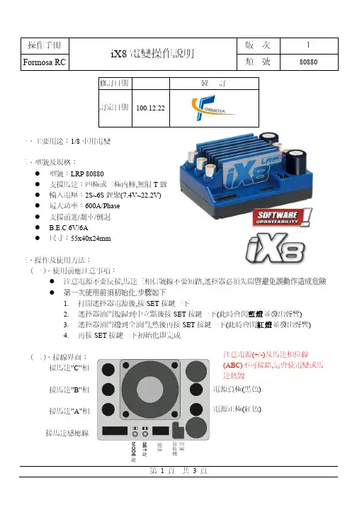
电调操作说明ICE系列ESC操作说明技术参数(ICE 45A- 150A)2-6S LiPo,6-18 NiMH(ICE HV60A,HV100A)4-12s LiPo, 12-36 NiMH(ICE HV120,HV180HV) 4-14s LiPo,5-15s(LiFePO4),12-42 NiMH,- SBEC :5.5V,6A(高压系列无BEC输出)- 低电压保护- 光电耦合器- 定速模式- 软启动- 激活惯性滑行(自动旋转),- 自动进角或者六段进角调节- 持续可调整的F3A的刹车- 3段可调节的电动势刹车- 切换频率:8 to 16 kHz- 速度限制:240,000转(2极马达)- 温度和超载警告- 消火花电路(防打火设计)- 可用于飞机与直升机- 可用编程卡编程初始化接通电源打开遥控器时你将听到三声降调。
然后是与之电池数量相关的蜂鸣声(4S时连续快速响4声,5S 与6S以此类推)。
当连接7至14s的电池会产生两声高音两声低音;之后将会产生三声升调,这时ESC可以开始工作。
如果马达转动方向错误,请仅交换马达三根线的任意两根电线。
速度控制器有固定的油门曲线设置,这样确保所有的遥控器的停止点和全油门点是成线性连接。
所有可编程遥控器,油门范围应设置为默认(± 100%),中心点设置为零和油门微调启用。
然而,有些类型的遥控器油门范围需要进行校正。
关于油门行程一定要设置2个末端点位,一个点位是油门杆在最低的位置时马达是停止的,还有一个点位置是全油门时马达是全功率的,LED指示灯熄灭表示全油门了。
在出厂时进角调节为18°,中等刹车,并且低电压保护值为3.1V 的锂电池模式。
如果在加速时出现了叫声或其他的不正常声音,那么进角要加大。
如果进角增加到30°还不能改善,那么你的马达将是超负荷的,,此时使用一个较小的螺旋桨或降低电压,或更换一个性能更好的马达。
如果当马达停止工作时你听到两声重复的蜂鸣声,表示电池的电压已低于设定值。
1、启动阶段1)红灯每2秒闪一次,且伴为“哔-,哔-”警示音:电调未检测到油门信号。
2)绿灯闪烁N次:上电时自动进行锂电节数检测,闪烁N次表示当前锂电为N节。
2、行驶阶段1)油门摇杆处于中点区域,红色和绿色LED均熄灭。
2)前进时,红色LED恒亮;当油门处于正向最大(100%油门)时,绿色LED也会点亮。
3)倒退时,红色LED恒亮。
3、相关保护功能触发时,LED状态含义:1)红灯持续闪烁(单闪,“☆,☆,☆”方式闪烁):电池电压太低,电调进入电池低压保护状态。
2)绿灯持续闪烁(单闪,“☆,☆,☆”方式闪烁):电调温度过高,电调进入过热保护状态。
故障现象解决方法可能原因1、电池电压没有输入到电调;1、检查电池与电调是否连接可靠,如有焊接不良,请重新焊好;上电后电机无鸣音,指示灯也未闪亮06编程设定说明08电调状态指示灯(LED)说明09保护功能说明10故障快速处理01声明Seaking Pro 120A • Seaking Pro 160A船用无刷电子调速器使用说明书· 调试请将船模架起,确保船桨不会碰到人或其他物体,以免发生安全事故。
03产品特色· 轻量化设计,适合竞赛要求。
· 出色的防水性能(160A电调采用塑封工艺,120A电调采用纳米镀膜工艺),一般情况下无需做防水处理即可直接使用(注:使用后请将电调插头吹干,以免锈蚀)。
· 内置超强开关模式BEC,持续电流达到4A,瞬间达到8A,且支持 6V和7.4V 切换,轻松驱动各种强力舵机及高压舵机。
· 采用好盈专利铜片导热技术,配合水冷模块和极低热阻的内部MOSFET,使得电调的耐流能力及可靠性大大增强。
· 使用顶级竞赛核心程序,具有一流的操控手感及丰富的调节选项,适应各种比赛环境。
· 行业首创的超速功能(即:开启Turbo进角),让马达瞬间释放更强动力,轻松超越竞争对手。
8-Channel Home Theater Amplifier PT8000CHMulti-Zone Audio Source Control,Rack Mount Amp, 8000 WattRead through this user manual before using the product to ensure its correct use. Keep this manual for future reference.The PT8000CH contains the excellent performance and reliability that PYLEUSA products have been recognized for. The PT8000CH features the exibility needed for demanding custom installation applications. It is ideal for use in home theater, stereo, multi-room, multi-zone and commercial applications.For best performance, please carefully read the instructions in this manual.TABLE OF CONTENTSFeaturesFront Panel DiagramRear Panel DiagramSystem Design & Operation Considerations System Design ExamplesDiagram 4 - Multi Room InstallationDiagram 5 - Multi-Zone Installation #1Diagram 6 - Multi-Zone Installation #2Diagram 7- Home Theater/Multi-Room Installation Installation ConsiderationsInstallationOperationTroubleshootingSpeci cations3 4 4 6 8 9 10 11 12 13 14 18 19 212FEATURESAudiophile DesignSophisticated design and superior internal components result in outstanding sound quality, performance and long term reliability.Advanced ProtectionEach channel is individually protected. If the circuitry determines that a channel must be shutdown for protection, a rare occurrence, only the channel a ected will be turned o . The other channels will continue to play. Once conditions return to normal, the a ected channel will be turned back on and operate as normal. Flexible Input SelectionEach of the 8 channels can be assigned a variety of source inputs. A dedicated input can be assigned to each channel. Each channel can also be con gured to play common signals from the Bus or Auxiliary inputs. This provides the exibility needed in sophisticated custom audio installations.BridgingThe power output of adjacent channels can be combined to provide extra power when needed in certain areas. This is easliy accomplished by ipping a single switch. Individual Channel Level AdjustmentsEach channel has its own level adjustment. This allows the loudness of each speaker to be perfectly matched to its area.Multiple Power Modes and Output TriggerThere are three ways to turn the ampli er ON: constant, trigger and audio sense. This allows the ampli er to operate seamlessly as part of a sophisticated custom installation. A separate output trigger allows the ampli er to activate other components via voltage trigger.3DIAGRAM 1 FRONT PANEL1. POWER SWITCHMaster power switch. Turns o power to ampli er and Power Mode Circuitry.2. POWER OUTPUT LEVEL INDICATORThis is level meter which shows outputs levels of ch 1-2 ch 3-4 ch 5-6 & ch 7-8 condition on the operation. Therefore, you can see output condition thru this master indicator.DIAGRAM 2 REAR PANEL41-2. Main bus inputs allow outputs from receivers, CD players, TVs, or any stereoaudio sources to be ampli ed across all channels for easy multi-roomapplications. Auxiliary inputs allows an addition audio source to be played on any channel that is switched to AUX .3-4. Bus outputs allows the bus inputs to be sent to other ampli ers or a daisy chain without the need for “Y” cable splitters. Auxiliary output allows you to daisychain the input to other audio sources.5. Bridging switch allows you to easily double the power output by coupling two channels together.6. Level controls for each channel.7. Input Selection switch allows you to select between the common bus andauxiliary inputs or the individual channel input.8. One switch allows you to select which stereo Input channel will play through the speaker outputs: left, right, or left and right combined. lf switched to Left + Right, both input channels are combined.9. Gold plated individual channel inputs allow you to connect di erent audiosources to each channel.10. Line signal output11. Voltage Selector 110-220V12. The Power Mode switch is used to toggle between three di erent triggermethods to power up the ampli er.13. 12V output to turn on other devices when ampli er is powered up.Connect to projector screens, powered drapes, or other devices with voltage triggers.14. 12-15V A/C or D/C input to trigger power up with voltage from anotherdevice, such as a receiver.15. Speaker channel output binding posts.16. Speaker channel bridged mode binding.17. 3-Prong removable power plug.18. Fused AC5SYSTEM DESIGN & OPERATION CONSIDERATIONSTo best understand system design and operation of the PT8000CH, it is useful to understand the following terms and features as they relate to the PT8000CH. Multi-RoomA system design that plays the same source at the same time in all rooms.If a change is made in one room, the same changes takes place in all other rooms. For example, if a listener changes from CD to Tuner in the bedroom, the same change will be heard in the kitchen.Note: With the use of volume controls or speaker switchers the volume of each room can be controlled separately of the other rooms.Multi-ZoneA system design that allows di erent sources to be played in each room. A change in one room can be made without changing the other rooms. For example the CD player can be heard in the bedroom while the kitchen is playing the tuner. BridgingThe combining of 2 channels to create one mono channel. It is useful when more volume is needed in a particular area.SourceComponent, audio or video, that provides an audio signal. Examples are CD, VCR, DVD, tape deck and tuner. The source provides the audio information that is ampli ed by the PT8000CH.ChannelA distinct unit of the ampli er that provides output to one speaker. On thePT8000CH the input to each channel can be con gured to select from the BUS INPUT, the AUX INPUT or that channel’s unique CHANNEL INPUT. Two adjacent channels can be bridged to provide higher power to one speaker.Level ControlsAllows any of the channels to be adjusted independently to raise or lower the output of each channel. This may be used to control the speaker output in order to balance di erent rooms or areas of the system.6BUS* AUX* LINE SwitchAllows each channel to play a variety of di erent inputs. Depending on the switch position the channel ampli es the signal connected to the BUS input, the AUX input, or its own LINE input.R R + L L SwitchWhen either a BUS or AUX input is selected, this switch is used to direct the channel to play the left signal from the input “L” or the right signal from the input “R”, or a combined right and left signal from the input “R+L”.Bus InputAllows the signal from a source to be distributed to any of the 12 channels on the ampli er.Auxiliary InputsAllows the signal from a secondary source to be distributed to any of the 12 channels of the ampli er.Power Mode SelectionThere are three ways to turn the ampli er on and o . Use the following list to decide which mode will work best for your application. See Diagram 3 below. 1. ConstantUse this selection when you wish to manually turn the ampli er on and o byusing the front mounted power button.2. TriggerUse this selection if you wish the ampli er turn on when it receives voltage(12-15V A/C or D/C) from an external source and turn o once that voltage has stopped. Some components have voltage outputs that are designed for this use. In addition there are devices that can be used as part of an automated system that will provide voltage to enable the mode. The voltage source must beconnected to the trigger-input jack on the back of the ampli er.3. Audio SenseUse this selection when you want the ampli er to turn on when the ampli er’s main input receives an audio signal. At the moment that either the left or right input jacks receive a signal the ampli er is turned on. Once the signal stops the ampli er waits 3 minutes and then turns o .78DIAGRAM 3: POWER MODE SELECTIONSYSTEM DESIGN EXAMPLESThere are many ways to con gure the PT8000CH ampli er. The following pages contain some typical installation examples. Use these examples to generate ideas for your system design.Multi-Room Installation Example (Diagram 4)This illustrates the simplest use of the PT8000CH, distributing audio throughout the home. In this example only one source can be selected at a time, all pairs of speakers have the same audio signal available. The Input Selection switch is set to “BUS” on all channels. Adjacent channels are assigned left and right.Multi-Zone Example #1 (Diagram 5)This illustrates the simplest way to provide an audio signal to one area that is independent of the main audio signal. Zone 2 uses a CD player connected to just that Zone. The rest of the system operates Zone 1 and is connected to the preampli er/receiver. The Input Selection switch on channels 1-10 is set to “BUS” with adjacent channels assigned left and right. The Input Selection Switch on channels 11 and 12 are set to “LINE”.Multi-Zone Example #2 (Diagram 6)This illustrates the ability to listen to di erent audio signals in each zone, indepen-dent of every other zone. The system relies on a multi-zone preampli er or up to 6 independent preampli ers.The Input Selection switch on each channel is set to “LINE”12-15V AC/DC TRIGGER INPUT 12-15V AC/DCTRIGGER INPUT 12V CONTROL OUTPUTAUDIO SENSE CONSTANT2.1mm x 5.5mm Power Input Jack Mode Switch3.5mm Power Output JackHome Theater / Multi-Room Example (Diagram 7)This con guration allows the user to access the sources connected to a home theater receiver for use in a multi-room installation. It relies on the home theater receiver having a multi-room or similar output.The Input Selection switch on each channel is set to “BUS” with adjacent channels assigned left and right.DIAGRAM 4 MULTI ROOM INSTALLATION9 10DIAGRAM 5 MULTI ZONE INSTALLATION #1DIAGRAM 6 MULTI ZONE INSTALLATION #21112DIAGRAM 7 HOME THEATER/MULTI ROOM INSTALLATIONINSTALLATION CONSIDERATIONSDO:• Place the amplifier with the feet resting on a solid flat level surface.• Place the amplifier in a well-vented area to provide proper cooling. In areas thatlack proper ventilation, such as tight cabinets or racks, it may be necessary toinstall small fans to create air movement.DON’T:• Don’t block the ventilation holes on the top or bottom of the amplifier.Never place it on carpeting or similar material.• Don’t place the ampli er in any other position other than horizontal with the feet down. Never place on its side or resting on the back where the terminals arelocated.• Don’t the amplifier near heat sources, or in an area that it would be exposed tomoisture.YOU SHOULD KNOW• The power supply is very large and therefore may cause a hum to be heard insome components if they are placed very close to the ampli er.13INSTALLATIONCAUTION: All connections and switching must be done with the ampli er’s master power switch positioned to “o ”.Select the Power Mode SelectionRefer to the Power Mode Selection area under installation considerations to determine which setting to use to turn the ampli er on. Once you have determined which mode you will be using set the switches as outlined in the following chart:14Selecting Inputs (See Diagrams 8 & 9)Each channel is capable of delivering the source from many inputs. The three main inputs are BUS, AUX and LINE IN. The selection for these inputs is donevia the Input Selection switch, marked “BUS-AUX-LINE”. To select a source for each channel, follow the steps below:1. Select the desired source input. Set the Input Selection switch to BUS (will playsource connected to the BUS INPUT), AUX (will play source connected to theAUX INPUT) or LINE (will play source connected to the LINE IN).Diagram 8BUS.AUX.LINE2. The BUS and AUX inputs each have a left and right input. The left, right orcombined left and right signal from these may be selected via the switchmarked “R R+L L”. Select the side you want the channel to deliver. Selecting “R” ± will play the right channel of the selected input. Selecting “L” will play the leftchannel of the selected input. Selecting “R+L” will play the combined signals ofright and left.Diagram 9R R+L RSelecting Bridge Mode (See Diagram 10)Under normal operation, this should be left in the 8 ohm position. It is sometimes desirable to combine two channels into one through bridging. The output of the combined channels can then be used to power one speaker.To bridge two adjacent channels rst make sure that the Impedance Switch isin the 8ohm position. Next move the switch marked “BRIDGE” to the “ON” position.1516The speaker must be connected to the terminals immediately under the “BRIDGED” text as indicated in Diagram 10. All input selection and settings for the bridged channels will be done on the channel to the left.Do not connect more than one speaker to the outputs of the bridged channel.Control OutputThe 12V output jack on the back of the ampli er can be used to turn on a variety of components equipped to be activated when they receive a 12V DC output. Voltage is only delivered to the jack when the ampli er is “on” or active. When the ampli er turns o , the voltage ceases.Before connecting another device to the 12 output please make sure that the device can accept 12V DC at 150ma. To connect the output to another device you must access the output jack with a two-conductor plug that ts into the 3.5mm jack. Be aware that the tip of the plug will be (+). If you are unsure about using this feature please contact an authorized PYLEUSA dealer for assistance.Connecting the Speaker WiresCAUTION:Only make connections when the ampli er is turned o .Wires to speakerUsing Standard Connections (See Diagram 11)For best performance use high quality speaker cables. The banana plug outputs on the back of the ampli er allow for a variety of ways to connect your speakers to the ampli er.Diagram 11: Binding Post DetailOnly make connections when the ampli er is turned o . application.Audio OutputsSources connected to the “BUS” or “AUX” inputs can be forwarded to other components or ampli ers by connecting to the corresponding output sectionsto the right of each input section. By using standard audio patch cables, you can connect these outputs to the inputs of another ampli er. Up to 5 ampli ers canbe daisy-chained together.AC PowerPlug the socket of the AC cord supplied with the ampli er into the receptacle on the rear of the ampli er. Plug the 2 prong plug directly into a 120V 60Hz wall outlet. CAUTION: Do not plug the ampli er into the preampli er or receivers switched outlet. If you wish to have the ampli er turn on once the preampli er or receiveris activated, use one of the turn on modes, voltage or audio.Turn to tightenInsert Banana Plug17OPERATIONSee Diagram 1for the location of the following:Power SwitchThe switch marked “Power” on the front panel of the ampli er will turn o all ampli er circuitry no matter which turn on mode is selected.Refer to the “Power Mode Selection” section for further information.Active LEDWhen lit, the Active LED indicates that the ampli er is operating. Refer to the “Power Mode Selection” section of this manual for further information. Protection LEDsWhen lit the “Protection” LEDs located on the front of the ampli er indicate that either a fault in the wiring, the speaker, or the ampli er has caused the channels associated with the LED to shut down.Level Adjustment KnobsThe level adjustment knobs on the back panel of the ampli er can be used to adjust the level of each channel. There are many reasons for needing to adjust the level. You many wish to closely match other levels in the system, or you may wish to limit the volume level in an area, such as a child’s room.18TROUBLESHOOTINGThe ampli er is designed to function trouble-free. Most problems occur becauseof operating errors. If you have a problem please check the troubleshooting listrst. If the problem persists, contact your authorized dealer.19This product can expose you to a chemical or group of chemicals, which may include “Nickel Carbonate” which is known in the state of California to cause cancer, birth defects,or other reproductive harm. For more info, go to https:/// 20FEATURES:• Multi-Zone Audio Source Ampli er System• High-Powered & Distortion-Free Audio Distribution• 8-Channel Sound Processing Amp Design• Integrated 4-Channel Bridgeable (Bridge) Switches• Front Panel Color LED Graphic Audio Level Display• Independent Channel Rotary Level Control Knobs• Channel Con guration: Left/Right/Mono - Bus/AUX Input• Gold-Plated Audio/Speaker Connectors• 5-Way Speaker Binding Posts (Banana Plug) Outputs• Pass-Through Output for External Ampli er Linking (Daisy-Chaining)• Individual Channel Safety with Protection & Overload Circuitry• Master Power Button, ON/OFF• Universal Rack Mount Compatibility• Perfect for Home Theaters & Multi-Room Audio Control• Used in Home, O ce & Business ApplicationsWHAT’S IN THE BOX:• 8-Channel Ampli er• Power CableTECHNICAL SPECS:• MAX Power Output: 8-Ch. x 1000 Watt• RMS Power Output: 100W x 8-Ch @ 8Ohm• T.H.D.: <1%• Rack Mountable: 4U Rack Space• Power: 115/230V Switchable (DC 12-15V)• Dimension (W x D x H): 19.0'' x 19.3'' x 7.1''21Questions? Issues?We are here to help! Phone: (1) 718-535-1800Email: *******************。
好盈sc8rtr说明书HW25A说明书兼容好盈科技无刷电调编程设定卡输出能力:持续电流25A,短时电流30A(不少于10秒);电源输入:2-3节锂电池组或5—12节镍氢、镍镉电池组;BEC输出:2A (线性稳压模式-linear mode);最高转速:2极马达210000转、分钟,6极马达70000转、分钟,12极马达35000转、分钟;尺寸:45mm(长)24mm(宽)11mm(高);重量:22g(含散热片);产品功能1、安全上电功能:接通电源时,无论油门摇杆处于任何位置均不会立即启动电机,避免造成人身伤害;2、油门行程校调功能:适应不同遥控器油门行程的差别,提高油门响应的线性度,具备平滑、细腻的调速手感和一流的调速线性;3、程序设定项目:●刹车设定:无刹车、有刹车,出厂默认值为无刹车。
●电池类型:Li-(锂电池)、Ni-(镍镉或镍氢),默认值为Li-(锂电池)●低压保护模式:降低功率、关闭输出,默认值为降低功率。
●低压保护阈值:低、中、高,默认值为中截止电压。
◆当设定使用的是Li-电池,则自动判断锂电颗数,低、中、高情况下每颗电池的截止电压分别为:2、6V、2、85V、3、1V。
◆当设定使用的是Ni-电池,电调上电时自动侦测电池组的电压,低、中、高情况截止电压为开机时输入电压的0%、45%、60%(0%意味着不做低压保护)●启动模式:普通、柔和、超柔和启动,默认值为普通启动。
◆普通启动适用于固定翼,可以在0。
2秒内迅速启动马达◆柔和启动、超柔和启动适用于直升机;柔和启动和超柔和启动的初始转速都比较低,从启动到全速分别需要1秒和2秒钟,但启动后若关闭油门,3秒内再次启动时则均以普通模式启动,以免在做一些特技动作飞行时因反应过慢而导致摔机。
●进角:低、中、高,默认值为中进角。
一般情况下,低进角可以适应更多的马达,但为提高效率,建议2极马达使用低进角,6极以上马达使用中进角。
为提高转速,可以将进角设为高进角。
KUBE KX-8无刷调速器内测版简易说明书
KX-8是一款高性能的、泛用性强、兼容性强的车模无刷电机控制器,
支持市场上的2级、4级、6级乃至更多级的电机。
支持各种有感无感电机,能运行在有感模式和无感模式下,即使比赛中感应器损坏,也能确保电调继续运行
支持2-6S锂电池,使得能全面应用与1:10短卡、1:8短卡、1:8电越、1:8大脚。
全铝合金外壳,超强散热。
参数:
输入电压:6V-25V(2S-6S)
过电流能力:取决于电池(按好盈参数标准约为170A)
支持电机KV:2S状态下不限
4S状态下2800KV以下
6S状态下2000KV以下
BEC类型:开关型BEC
BEC输出:6V3.5A
关于KX-8的低压保护
更换不同电压的电池。
如2S换成3S,需要重新设置一下电调电压保护类型,以确保低压保护正常启动。
(注意未设置正确的电池类型将会导致电池损坏或者电调无法启动!)
电调M按键为模式选择V按键为数值设定
LED1为弱(低)~LED7为强(高)
设置电调中立点
遥控器CH2通道方向设置为NOR
1.打开电调开关
2.按住M按钮3秒
3.这时中间的LED会闪烁,此时正在设定油门中间点,请手离开遥控器即可,等待若干秒、
4.过一会儿,右侧LED会闪烁,此时正在设定油门正向最大点,请油门按到最大,等待若干秒
5.过会儿,左侧LED会闪烁,此时正在设定刹车最大点,请前推刹车到最大,
参数设定
进入参数设定,开启电调后,按一下M按键,此时LED1会闪烁,代表着参数类型的选择,此时再按一下M按键,LED2会闪烁,直至LED7不断可以循环,不同的LED闪烁代表着
不同的参数类型。
当某个LED对应的参数类型闪烁时,按一下V按键,便进入了相对应的参数类型的选择,此时恒亮的灯的数量代表着这个参数的参数值,左侧为最小,右侧为最大。
此时重复按下V按钮可以改变当前这个参数值乃不断循环。
LED1:拖刹DRAG BRAKE(放开油门后便刹车)
LED1亮为最小,随着LED亮的次数最多便是增大
LED2(无刷模式下)刹车力度兼倒车速度
左侧为最小,右侧为最大,全程为13段设置
LED3:启动力量
左侧为最小,右侧为最大,全程13段设置,启动力量请调整到合适的程度,过高的启动力量将会导致车辆磨损增加以及电池,电机发热。
LED4:中立点死区大小
左侧为最小,右侧为最大各种遥控器随着品质的不一样,在静止的状态下也会存在油门的浮动,这会导致电调的误判和错误启动,所以需要中立点死区设置,一般建议品种高的遥控器调低参数,以确保高的灵敏度,品质低的遥控器建议调高,以避免错误的操作。
LED5:油门曲线
LED1亮
-最溫柔的曲線,凹曲線
LED1~2亮-亮溫柔的曲線,凹曲線
LED1~3亮-直線曲線(推荐)
LED1~4亮-爆力曲線,凸曲線
LED1~5亮-最暴力曲線,凸曲線
LED1~6亮-微高定曲線
LED1~7亮-自微低曲線
LED6:电机类型
LED1亮-无刷,前进\刹车
LED1~2亮-无刷,前进\刹车\倒退
LED1~3亮-无刷,前进\刹车\倒退延迟回到中立点2秒后再按才是倒车(推荐,比赛时跳坡
可以防止误启动倒车)
LED1~4亮-有刷,前进/刹车
LED1~5亮-有刷,前进/刹车/d倒退延迟
LED1~6亮-有刷,前进/刹车/倒退
LED1~7亮-无刷,电机方向旋转(改变电机旋转方向),前进/刹车、倒退延迟
LED7:电池低压保护
如更换不同电压类型锂电池时,一定要重新设定电池电压类型!不然会导致电池过放或者电调不启动!
LED1亮-无保护,适合NICD/NIMH电池
LED1-2亮-6.4V保护(2S锂电适用)
LED1~3亮-9.6V保护(3S锂电适用)
LED1~4亮-12.8V保护(4S锂电适用)
LED1~5亮-15V保护(5S锂电适用)
LED1~6亮-18V保护(6S锂电适用)
LED1~7亮-6.8V保护(2S锂电娱乐适用)
电机辅助惯性程序设定方法:
什么是电机辅助惯性程序?
如果选用磁力较大的电机,即使没有设定过拖刹,放开油门的时候,电机也会产生比较明显的阻力,降低车速,影响操作者的手感,所以为了对抗这种阻力,让操作者放开油门的时候也有一种滑行的感觉,建议开启辅助惯性程序,参数值越高,对抗这种阻力的值也越大。
辅助惯性程序设定方法。
参数设定完成后,电调会重新启动自检,刚才所设定的参数便生效
进入LED6:电机类型
将数值设置为LED4&5&6,也就是有刷模式下的任意状态,
然后按M按键选择LED2参数模式,此时参数模式便是辅助惯性程序数值设定,此时按下V可以设定辅助惯性程序大小。
设置好惯性程序大小后等待电调重启
重启后电调应该处于LED1&2,6&7闪烁状态,电机类型出错(完全正常因为此时电机类型为有刷模式)
此时再按M进入程序设定,LED6电机类型菜单,将LED6电机类型的参数设置为您之前的无刷对应的状态,再等待电调重启后,惯性程序参数设置完毕!
各种类型的LED闪烁含义
LED全部闪烁:没有收到接收器信号,请检查接收器系统。
LED1,2,3闪烁:刹车过大开机时遥控器刹车过大,保护状态,回到中间位置后电调便会启动,如更换过遥控器,请重新设定油门中位
LED5,6,7闪烁:油门过大开机时遥控器油门过大,保护状态,回到中间位置后电调便会启动,如更换过遥控器,请重新设定油门中位
LED1,3,4闪烁。
电压保护启动,请检查更换电池,或者选择正确的电池电压类型参数
LED3,4闪烁:接线存在短路,请检查电调接线和导线连接。
LED4闪烁:正常
LED1&2,6&7闪烁,有刷无刷模式选择出错,电机连线出错,如果电机连线没有出错,有刷模式无刷模式也未有出错,请联系售后。