TC4钛合金表面等离子喷涂Al2O3-13wt%TiO2涂层及激光重熔研究
- 格式:pdf
- 大小:623.43 KB
- 文档页数:5
Ti-6Al-4V(TC4)Ti-6Al-4V(TC4)钛合金是双相合金,具有良好的综合性能,组织稳定性好,有良 好的韧性、塑性和高温变形性能,能较好地进行热压力加工,能进行淬火、时效 使合金强化。
热处理后的强度约比退火状态提高50%~100%;高温强度高,可 在400℃~500℃的温度下长期工作,其热稳定性次于α钛合金[35]。
表3-2 钛合金Ti-6Al-4V 成分钛合金Ti6Al-4V 合金碳(最大) 0.10%铝 5.50至6.75% 氮 0.05% 氧气(最大) 0.020%其他,合计(最大) 0.40% *其他,每个(最大)= 0.1%钛 平衡钒 3.50至4.50% 铁(最大) 0.40% 氢(最大) 0.015%比重 0.160弹性模量(E )的 15.2 x 10 3 ksi?贝塔Transus 1800 to 1850 °F? 液相线温度 2976 to 3046 °F 固相线温度 2900 to 2940 °F 电阻率-418 °F 902.5 ohm-cir-mil/ft?73.4 °F 1053 ohm-cir-mil/ft? 986 °F 1143 ohm-cir-mil/ft?典型的室温强度计算退火钛6Al-4V 的:极限承载强度1380年至2070年兆帕(200-300 ksi ) 压缩屈服强度825-895兆帕(120-130 ksi ) 极限剪切强度480-690兆帕(70-100 ksi ) Ti-6Al-4V 的线膨胀系数只有8.8×10⁻⁶K-1.钛是一种新型金属,钛的性能与所含碳、氮、氢、氧等杂质含量有关,最纯的碘化钛杂质含量不超过0.1%,但其强度低、塑性高。
99.5%工业纯钛的性能为:密度ρ=4.5g/cm3,抗拉强度σb=539MPa ,伸长率δ=25%,断面收缩率ψ=25%,弹性模量E=1.078×10⁵MPa ,硬度HB195。

tc4剪切强度1.引言1.1 概述概述部分应该简要介绍文章的主题和内容,可以提供一些背景信息,引起读者的兴趣。
根据给出的文章目录,我们可以在概述部分添加以下内容:概述部分:tc4是一种常见的钛合金材料,具有优异的力学性能和热处理可塑性,因此在航空航天、汽车制造、生物医疗等领域得到广泛应用。
在实际应用过程中,了解和掌握tc4的力学性能特点是非常重要的。
本文将重点研究tc4的剪切强度,通过定义和测量方法的介绍,深入探讨tc4剪切强度的相关特性和其影响因素,最终揭示其在实际应用中的应用价值和意义。
通过本文的研究,有助于提高对tc4材料的认识,为其在工程领域的应用提供指导。
1.2 文章结构文章结构的设计对于一篇长文的组织和表达起着关键作用。
本文以TC4剪切强度为主题,旨在深入介绍和探讨该材料的特性和应用。
文章结构的设计将是相当重要的,下面将对本文的结构进行详细规划。
在本文中,主要包含引言、正文和结论三个部分。
1. 引言引言部分首先对整篇文章进行一个概述,简单介绍TC4剪切强度的研究背景和重要性,使读者对本文的主题有一个初步的了解。
接着,对文章的结构进行说明,给读者一个整体的框架,使其能够清晰地理解文章的内容和脉络。
最后,明确本文的目的,即通过介绍TC4剪切强度的定义、测量方法、影响因素以及应用意义等方面的内容,为读者提供一个全面、深入的了解。
2. 正文正文部分是本文的重点,主要包括背景介绍和TC4剪切强度的定义和测量方法两个子部分。
2.1 背景介绍背景介绍部分将对TC4的基本情况进行简要说明,包括其组成成分、力学性质以及广泛应用的领域等方面的内容,以便读者对该材料有一个初步的了解。
2.2 TC4剪切强度的定义和测量方法本节将对TC4剪切强度的含义进行详细阐述,包括定义的解释、测量方法的原理和步骤等方面的内容。
针对TC4剪切强度的测量方法,可以介绍常用的实验设备和操作流程,以及相应的数据分析和结果讨论部分。


TC4钛合金阳极氧化着色膜不同电压下的耐腐蚀性能
王珊;刘志超
【期刊名称】《材料保护》
【年(卷),期】2018(51)7
【摘要】采用阳极氧化着色处理可以有效地提高TC4钛合金的综合性能。
以正交试验方法分析了氧化着色工艺参数对TC4钛合金阳极氧化膜的影响;利用扫描电镜(SEM)观察了氧化膜的形貌,使用X射线衍射仪(XRD)分析了氧化膜的物相,通过电化学试验对其耐腐蚀性进行了探讨。
结果表明:TC4钛合金阳极氧化着色的最佳工艺条件为温度45℃,氧化时间20 s,电压20 V,酸腐蚀时间40 s;决定氧化膜颜色的主要因素是氧化电压,随着氧化电压的变化,膜的颜色出现了规律性变化;阳极氧化处理后TC4钛合金表面形成了一层均匀、多孔的氧化膜,成分为Ti O2,且以金红石结构存在;阳极氧化着色处理可以改善TC4钛合金的耐腐蚀性能。
【总页数】4页(P91-94)
【作者】王珊;刘志超
【作者单位】青海大学机械工程学院
【正文语种】中文
【中图分类】TG174.451
【相关文献】
1.铝的阳极氧化和电解着色——Ⅲ.影响阳极氧化膜性能的因素
2.TC4钛合金阳极氧化及其PTFE复合涂膜耐摩擦磨损性能研究
3.铝阳极氧化膜不同封孔方法的耐腐
蚀性能研究4.TC4钛合金微弧阳极氧化膜层结构与性能的研究5.TC4钛合金阳极氧化着色膜显色规律探讨
因版权原因,仅展示原文概要,查看原文内容请购买。
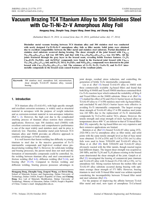
Vacuum Brazing TC4Titanium Alloy to 304Stainless Steelwith Cu-Ti-Ni-Zr-V Amorphous Alloy FoilHonggang Dong,Zhonglin Yang,Zengrui Wang,Dewei Deng,and Chuang Dong (Submitted March 19,2014;in revised form June 18,2014;published online July 17,2014)Dissimilar metal vacuum brazing between TC4titanium alloy and 304stainless steel was conducted with newly designed Cu-Ti-Ni-Zr-V amorphous alloy foils as filler metals.Solid joints were obtained due to excellent compatibility between the filler metal and stainless steel substrate.Partial dissolution of stainless steel substrate occurred during brazing.The shear strength of the joint brazed with Cu 43.75Ti 37.5Ni 6.25Zr 6.25V 6.25foil was 105MPa and that with Cu 37.5Ti 25Ni 12.5Zr 12.5V 12.5was 116MPa.All the joints fractured through the gray layer in the brazed seam,revealing brittle fracture features.Cr 4Ti,Cu 0.8FeTi,Fe 8TiZr 3and Al 2NiTi 3C compounds were found in the fractured joint brazed with Cu 43.75Ti 37.5Ni 6.25Zr 6.25V 6.25foil,and Fe 2Ti,TiCu,Fe 8TiZr 3and NiTi 0.8Zr 0.3compounds were detected in the joint brazed with Cu 37.5Ti 25Ni 12.5Zr 12.5V 12.5foil.The existence of Cr-Ti,Fe-Ti,Cu-Fe-Ti,and Fe-Ti-V inter-metallic compounds in the brazed seam caused fracture of the resultant joints.Keywords304stainless steel,amorphous foil,microstructure,shear strength,Ti-6Al-4V titanium alloy,vacuum brazing1.IntroductionTC4titanium alloy (Ti-6Al-4V),with high specific strength and excellent corrosion resistance,is widely used as structural material in aerospace with the purpose of weight reduction and as corrosion-resistant material in non-aerospace industries (Ref 1,2).However,the high cost due to the complicated smelting process of titanium alloys restricts their extensive applications.However,type 304stainless steel (304SS)with excellent corrosion resistance and comprehensive performance is one of the most widely used stainless steel,and its price is relatively low.Therefore,dissimilar metal joint between TC4titanium alloy and 304SS provides an effective approach to combine advantages of both materials.It is well known that fusion welding has difficulty in joining titanium to steel due to the massive generation of Fe-Ti intermetallic compounds and high-level residual stress pro-duced during welding (Ref 3).However,for solid-state welding and brazing processes,the parent metal does not melt and the formation of intermetallic compounds could be controlled.So,the welding between titanium alloy and steel concentrated in friction welding (Ref 4-8),diffusion welding (Ref 9-14),and brazing (Ref 15-19).Compared to friction welding and diffusion welding,brazing process possesses advantages injoint design,residual stress reduction,and controlling the generation of brittle Ti-Fe intermetallic compounds.Liu et al.(Ref 15)brazed Ti-6Al-4V alloy to 304SS with three commercially available Ag-based fillers and found that both BAg-8/304SS and Ticusil/304SS interfaces contained thick Cu-Ti-Fe reaction layer which reduced the wettability of BAg-8and Ticusil fillers on the 304SS substrate.Shiue et al.(Ref 16,17)studied the effect of Ni and (Ni)-Cr barrier layers on brazing Ti-6Al-4V alloy to 17-4PH stainless steel with Ag-based fillers,and concluded Ni and (Ni)-Cr barrier layers were effective in avoiding Fe-Ti intermetallic compounds.The largest average shear strength of Ti-6Al-4V alloy/17-4PH stainless steel joints was 243MPa due to the replacement of Fe-Ti intermetallic compounds by Ti-Cu-(Ni)and/or TiCr 2phases.However,the tensile strength and creep strength of most Ag-based alloys at temperatures above 400°C are inferior to that of Ti-based fillers (Ref 20);especially,the Ag-based fillers are very expensive and their extensive applications are limited.Botstein et al.(Ref 21)brazed Ti-6Al-4V alloy using 25Ti-25Zr-50Cu (wt.%)amorphous alloy as filler metal,and solid joints with the same tensile strength level as that of base metal were obtained.Ti-15Cu-25Ni and Ti-15Cu-15Ni (wt.%)alloy foils were used to braze Ti50Al50and Ti-6Al-4V alloys by Shiue et al.(Ref 20).Both Ti50Al50and Ti-6Al-4V alloys obviously reacted with the filler metals,though reacted region had different shapes.The largest shear strength was acquired as 280MPa,and the Ti 2Ni and Ti 3Al phases existing in the brazed seam deteriorated the shear strength of the joint.Ganjeh et al.(Ref 22)investigated the brazing of commercial pure titanium and Ti-6Al-4V alloy with Ti-based (Ti-27Zr-14Cu-13Ni,wt.%)amorphous foil.Strong reaction between the molten filler and Ti-6Al-4V alloy substrate occurred during brazing with opti-mum average shear strength of 571MPa.However,brazing titanium to steel with Ti-based filler metal was seldom reported considering the incompatibility between Ti-based filler metal and steel substrate (Ref 23).For the purpose of improving the affinity between Ti-rich filler metal and steel,new types of amorphous Ti-Cu-basedHonggang Dong,Zhonglin Yang,Zengrui Wang,and Dewei Deng ,School of Materials Science and Engineering,Dalian University of Technology,Dalian 116024,People Õs Republic of China;and Chuang Dong ,Key Lab of Materials Modification,Dalian University of Technology,Ministry of Education,Dalian 116024,People Õs Republic of China.Contact e-mail:donghg@.JMEPEG (2014)23:3770–3777ÓASM International DOI:10.1007/s11665-014-1145-y 1059-9495/$19.00filler metals with competitive cost were designed in this paper by reducing Ti content but adding V in the filler.It is well known that Ni and Zr can significantly improve the glass-forming ability of Ti-Cu alloys (Ref 24)and V has infinite solid solubility with both Fe and Ti,so the composition of the filler metal was determined as Cu-Ti-Ni-Zr-V .Then the TC4titanium alloy and 304stainless steel were brazed with the developed filler metals,and the microstructure and mechanical properties of the brazed joints were investigated.2.Experimental ProceduresThe base metals to be brazed are TC4titanium alloy and 304stainless steel with dimensions of 209892mm and 4592091.3mm,with the chemical composition of Ti-6Al-4V (wt.%)and Fe-0.08C-19Cr-9Ni-2Mn-1Si (wt.%),respec-tively.The developed Ti-Cu-based amorphous alloys,Cu 43.75Ti 37.5Ni 12.5Zr 12.5V 12.5and Cu 37.5Ti 25Ni 6.25Zr 6.25V 6.25(at.%)with dimensions of 50-l m thick and 2-mm wide,were prepared as filler metals by melt spinning.The XRD patterns in Fig.1reveal the amorphous structure of two foils with uniform composition and good flowability in melting state.Differential thermal analysis (DTA)was performed to determine the melting ranges of two filler metals.According to the DTA results,the Cu 43.75Ti 37.5Ni 6.25Zr 6.25V 6.25foil has a melting range from 828to 849°C,and the Cu 37.5Ti 25Ni 12.5Zr 12.5V 12.5foil from 859to 876°C.Generally,the brazing temper-ature is 30-90°C above the liquidus of filler metal (Ref 25),so the brazing temperature in this paper was 900°C for Cu 43.75Ti 37.5Ni 6.25Zr 6.25V 6.25foil and 930°C for Cu 37.5Ti 25Ni 12.5Zr 12.5V 12.5foil.The faying surfaces of the workpieces were polished with SiC papers up to grit 1200and ultrasonically cleaned in acetone prior to brazing.Then they were assembled into a sandwich as shown in Fig.2.The filler metal was placed between the workpieces,and a graphite block with gravity of 1kN wasplaced upon the assembly to keep the workpieces and filler metal closely contact with each other.The brazing process was conducted in a furnace with a vacuum atmosphere of 4910À3MPa.The heating rate was set at 10°C/min through-out the experiment.Before heated up to the brazing temper-ature,the specimens were preheated at 800°C for 5min for temperature homogeneity.Then the assemblies were brazed at 900or 930°C for 10min.For each set of brazing parameters,four couples of specimens were brazed.One was used for the microstructure examination,and the other three were tested to obtain the average shear strength.The brazed joints were cut by a wire cutting machine,then rubbed with 1200#metallographic sandpaper,and finally polished with 0.5-l m diamond paste.Then the cross sections of the joints were observed with Olympus OLS4000optical microscope,and the elemental distribution in the brazed seam was examined using Shimadzu EPMA-1600electron probe microanalyzer with 1-l m beam spot at 15kV .The room temperature shear strength of the joints was evaluated with DNS100universal tensile machine.Fracture surfaces were observed with JSM-5600LV scanning electron microscope (SEM),and x-ray diffraction (XRD)was conducted with Bruker D8Focus x-ray diffractometer to determine the phases in theinterfaces.Fig.1XRD patterns and backscattered electron images of (a)Cu 43.75Ti 37.5Ni 6.25Zr 6.25V 6.25(at.%)and (b)Cu 37.5Ti 25Ni 12.5Zr 12.5V 12.5(at.%)fillermetalsFig.2The schematic diagram of assembling the workpieces and filler metalFig.3Microstructure of the joints brazed with(a)Cu43.75Ti37.5Ni6.25Zr6.25V6.25foil and(b)Cu37.5Ti25Ni12.5Zr12.5V12.5foilFig.4Backscattered electron image and EPMA map scanning results of the joint brazed Cu43.75Ti37.5Ni6.25Zr6.25V6.25(at.%)foilTable 1EPMA quantitative analysis results in locations A-F marked in Fig.4(a)(at.%)Location Fe Cr Ti Al Cu Ni Zr V A 66.8727.46 2.510.420.650.530.03 1.53B 11.24 1.6950.77 4.4323.82 4.57 1.36 2.13C 4.140.7139.697.8130.16 4.2811.06 2.16D 7.160.7763.26 1.8116.78 6.00 1.83 2.40E 3.77 1.2267.477.5712.38 1.79 1.89 3.91F2.890.7073.349.556.311.070.365.78Table 2EPMA quantitative analysis results in locations A-F marked in Fig.5(a)(at.%)Location Fe Cr Ti Al Cu Ni Zr V A 66.7725.98 2.920.520.58 1.210.00 2.02B 14.28 2.9151.48 5.5414.30 4.91 1.49 5.10C 8.48 2.5439.659.0415.86 6.1411.96 6.33D 4.96 1.5368.41 5.469.42 2.67 1.94 5.62E 6.13 2.5764.80 6.347.98 2.36 1.668.16F2.620.7375.7711.192.961.220.365.16Fig.5Backscattered electron image and EPMA map scanning results of the joint brazed Cu 37.5Ti 25Ni 12.5Zr 12.5V 12.5(at.%)foil3.Results and DiscussionFigure 3shows the microstructure of the TC4titanium alloy/304stainless steel (304SS)joints brazed with Cu 43.75Ti 37.5Ni 6.25Zr 6.25V 6.25and Cu 37.5Ti 25Ni 12.5Zr 12.5V 12.5(at.%)at 900and 930°C for 10min,respectively.It can be seen that TC4titanium alloy and 304stainless steel substrates were tightly bonded through the filler metal.No pore and crack existed in the brazed seams.The thickness of the brazed seam was 80l m with Cu 43.75Ti 37.5Ni 6.25Zr 6.25V 6.25foil and 100l m with Cu 37.5Ti 25Ni 12.5Zr 12.5V 12.5foil.However,the thickness of the original filler metal was only 50l m.This phenomenon suggests that diffusion and reaction occurred between the substrates and filler metal.It can be seen that the original boundary between the TC4titanium alloy substrate and filler metal could not be discriminated in Fig.3(b).Especially,the boundaries between the steel substrate and filler metal present fine serrated shape indicating partial dissolution of 304stainless steel substrate.It is worth noting that the microstructure of the TC4titanium alloy substrate changed from fine equiaxed grain in the joint brazed with Cu 43.75Ti 37.5Ni 6.25Zr 6.25V 6.25foil to lamellar structure in the joint brazed with Cu 37.5Ti 25Ni 12.5Zr 12.5V 12.5foil,as shown in Fig.3(a)and (b).Higher brazing temperaturefor the joint brazed with Cu 37.5Ti 25Ni 12.5Zr 12.5V 12.5foil led to this difference.The backscattered electron images and EPMA map scanning results of the joints brazed with two foils are displayed in Fig.4and 5.It can be seen from Fig.4(a)and 5(a)that a thin diffusion layer (marked as A)existed in the interface between the steel substrate and filler metal.And Fe from the steel substrate obviously diffused into the brazed seam,in Fig.4(b)and 5(b).For the convenience of description,the gray,off-white,and light gray phases in the filler metal layer were marked with B,C,and D,respectively.E and F were marked in the reaction layers between TC4titanium alloy substrate and filler metal.The quantitative analysis results at A-F locations listed in Table 1and 2reveal that 11.24and 14.26at.%Fe were detected in location B.Location A,right in the interface between steel substrate and filler metal,contained 2.51-2.92at.%Ti and 1.53-2.02at.%V,indicating that Ti and V from the filler metal diffused into the steel substrate.It can be seen from Fig.4(d)and 5(d)that Cr also diffused into the filer metal layer and even into the reaction layer between titanium substrate and filler metal.However,Cu and Ni mainly existed in the filler metal layer and slightly diffused towards two base metals.By comparing the quantitative results in locations A,E,Fig.6Line scanning analysis results in the joints brazed with (a)Cu 43.75Ti 37.5Ni 6.25Zr 6.25V 6.25(at.%)foil and (b)Cu 37.5Ti 25Ni 12.5Zr 12.5V 12.5(at.%)foilFig.7Fracture location of the shear tested joints brazed with (a)Cu 43.75Ti 37.5Ni 6.25Zr 6.25V 6.25(at.%)foil and (b)Cu 37.5Ti 25Ni 12.5Zr 12.5V 12.5(at.%)foiland F in Table 1and 2,Ni showed better affinity with steel substrate,but Cu displayed better affinity with titanium substrate.Zr almost existed only in the off-white region C;the measurements in Table 1and 2indicate that 11.07and 11.96at.%Zr were detected in location C which were far higher than in other locations.Figure 6shows the line scanning results in the joints brazed with Cu 43.75Ti 37.5Ni 6.25Zr 6.25V 6.25and Cu 37.5Ti 25Ni 12.5Zr 12.5V 12.5foils.It can be seen that the curve for Ti can be divided into five stages from right to left.They are successively flat stage in TC4titanium alloy substrate,declining stage in the reaction layer between the titanium substrate and filler metal,valley stage in the off-white phase region,flat stage in the gray phase region in filler metal layer,and sharp drop stage in the interface between steel substrate and filler metal.It can also be clearly seen that the Fe and Ni contents dropped,but the Cr content raised,and a certain amount of Ti and V diffused into the 304SS substrate while observing the elemental curves in the interface between 304SS substrate and filler metal.The above phenomenon confirmed the quantitative analysis results in location A listed in Table 1and 2,indicating good compati-bility between 304stainless steel and Cu-Ti-Ni-Zr-V filler metals.All alloying elements except Ti in the filler metal diffused into the reaction layer between TC4titanium alloy substrate and filler metal,and their line scanning curves drop to the minimum in the interface between reaction layer and titanium substrate.The joints brazed with Cu 43.75Ti 37.5Ni 6.25Zr 6.25V 6.25and Cu 37.5Ti 25Ni 12.5Zr 12.5V 12.5foils were shear tested at roomtemperature.The results show that the shear strength of the joint brazed with Cu 43.75Ti 37.5Ni 6.25Zr 6.25V 6.25foil was 105MPa and that with Cu 37.5Ti 25Ni 12.5Zr 12.5V 12.5foil was 116MPa.However,the practical shear strength could be higher because two specimens brazed with Cu 43.75Ti 37.5Ni 6.25Zr 6.25V 6.25foil and one specimen brazed with Cu 37.5Ti 25Ni 12.5Zr 12.5V 12.5foil,during shear test,did not fail but the steel base metal bents over and the load was much higher than that for those specimens that broke through the brazed seam during shear test.Figure 7shows the cross sections of the fractured joints on TC4titanium side,and it can be clearly seen that the joints fractured through the gray phase (marked as location A in Fig.4and 5)in the filler metal layer.Figure 8shows the XRD patterns of the fractured surfaces.Cr 4Ti,Cu 0.8FeTi,Fe 8TiZr 3,and Al 2NiTi 3C were found in the fractured joint brazed with Cu 43.75Ti 37.5Ni 6.25Zr 6.25V 6.25foil,and Fe 2Ti,TiCu,Fe 8TiZr 3and NiTi 0.8Zr 0.3were detected in the joint brazed with Cu 37.5Ti 25Ni 12.5Zr 12.5V 12.5foil.The existence of Cr-Ti,Fe-Ti,Cu-Fe-Ti,and Fe-Ti-V intermetallic compounds possibly caused the fracture of the resultant joints.Because Ni can excellently solid solute with Fe in the steel substrate and Zr can completely solid solute with Ti in the titanium alloy base metal,and moreover,V has infinite solid solubility with both Fe and Ti;the fillers and two dissimilar base metals could mutually diffuse into each other to generate solid metallurgical bonding without forming massive harmful intermetallic compounds in the interfaces from the direct contact of Fe and Ti.Therefore,the developed Cu-Ti-Ni-Zr-V filler is supposed to be superior to Cu-Ti-Ni filler for joining TC4titanium and type 304stainless steel,due to the addition of Zr and V in the filler.The fractographs of specimens are shown in Fig.9,revealing brittle fracture features.The EDS analysis results in the marked locations are listed in Table 3.It can be seen that more than 26.66at.%Fe was detected on both sides of the joint brazed with Cu 43.75Ti 37.5Ni 6.25Zr 6.25V 6.25foil,especially in location 1;up to 49.40at.%Fe and 15.79at.%Cr were detected.It is significantly different from the results in other loca-tions,indicating that the joint brazed with Cu 43.75Ti 37.5Ni 6.25Zr 6.25V 6.25foil possibly fractured partially through the gray layer A.The results in locations 3,4,and 5in the joint brazed with Cu 37.5Ti 25Ni 12.5Zr 12.5V 12.5foil listed in Table 3were similar to the EPMA quantitative analysis results in gray layer (location B),as shown in Table 1and 2.These results suggest that the fracture location of the joint brazed with Cu 43.75Ti 37.5Ni 6.25Zr 6.25V 6.25foil is closer to the 304SS sub-strate,but the joint brazed with Cu 37.5Ti 25Ni 12.5Zr 12.5V 12.5foil fractured through the gray layer (location B).However,the amount of the intermetallic phases identified might be very small because the detected layers were very thin,which explains the discrepancy between the XRD and EDS analysis results.4.Conclusions(1)Vacuum brazing of TC4titanium alloy and 304stainless steel was conducted with newly developed Cu 43.75Ti 37.5Ni 6.25Zr 6.25V 6.25and Cu 37.5Ti 25Ni 12.5Zr 12.5V 12.5amor-phous alloy foils,and solid joints without pore or crack in the brazed seam were obtained.The filler metal showed excellent compatibility with 304stainless steel,and partial dissolution of 304stainless steel substrate occurred duringbrazing.Fig.8XRD patterns of fractured joints brazed with (a)Cu 43.75Ti 37.5Ni 6.25Zr 6.25V 6.25(at.%)foil and (b)Cu 37.5Ti 25Ni 12.5Zr 12.5V 12.5(at.%)foil(2)The shear strength of the joint brazed with Cu 43.75Ti 37.5Ni 6.25Zr 6.25V 6.25foil was 105MPa and that with Cu 37.5Ti 25Ni 12.5Zr 12.5V 12.5foil was 116MPa.The joints frac-tured through the brazed seam with brittle fracture fea-tures.(3)Cr 4Ti,Cu 0.8FeTi,Fe 8TiZr 3,and Al 2NiTi 3C phases were found in the fractured joint brazed with Cu 43.75Ti 37.5Ni 6.25Zr 6.25V 6.25foil,and Fe 2Ti,TiCu,Fe 8TiZr 3,and NiTi 0.8Zr 0.3compounds were detected in that with Cu 37.5Ti 25Ni 12.5Zr 12.5V 12.5foil.The existence of Cr-Ti,Fe-Ti,Cu-Fe-Ti,and Fe-Ti-V intermetallic compounds caused the fracture of the resultant joints.AcknowledgmentsThis work was financially supported by the National Natural Science Foundation of China (Grant No.51374048),the National Basic Research Program of China (973Program,Grant No.2011CB013402),the Fundamental Research Funds for the Central Universities,and the State Key Laboratory of Advanced Welding and Joining,Harbin Institute of Technology,Harbin,China.References1.R.R.Boyer,An Overview on the Use of Titanium in the Aerospace Industry,Mater.Sci.Eng.A Struct.,1996,213(1–2),p 103–1142.M.Yamada,An Overview on the Development of Titanium Alloys for Non-Aerospace Application in Japan,Mater.Sci.Eng.A Struct.,1996,213(1–2),p 8–153.Z.Sun and R.Karppi,The Application of Electron Beam Welding for the Joining of Dissimilar Metals:An Overview,J.Mater.Process.Technol.,1996,59(3),p 257–2674.A.Fuji,T.H.North,K.Ameyama,and M.Futamata,Improving Tensile Strength and Bend Ductility of Titanium/AlSI,304L Stainless Steel Friction Welds,Mater.Sci.Technol.,1992,8(3),p 219–2355.W.B.Lee,Y .J.Kim,and S.B.Jung,Effects of Copper Insert Layer on the Properties of Friction Welded Joints Between TiAl and AISI,4140Structural Steel,Intermetallics ,2004,12(6),p 671–678Table 3EDS analysis results in the locations marked in Fig.9(at.%)LocationFe Cr Ti Al Cu Ni Zr V 149.4015.7927.63 1.500.95 2.97 1.500.25226.66 3.7654.39 2.98 4.52 3.97 1.98 1.74315.99 2.9650.488.8510.04 5.38 2.89 3.40412.09 1.4160.99 3.52 6.68 6.07 5.62 3.61516.032.3855.423.0011.016.171.414.57Fig.9Fractographs of joints brazed with (a,b)Cu 43.75Ti 37.5Ni 6.25Zr 6.25V 6.25(at.%)foil and (c,d)Cu 37.5Ti 25Ni 12.5Zr 12.5V 12.5(at.%)foil.Note:(a,c)on steel side and (b,d)on titanium side6.W.B.Lee,M.G.Kim,J.M.Koo,K.K.Kim,D.Quesnel,Y.J.Kim,andS.B.Jung,Friction Welding of TiAl and AISI4140,J Mater Sci,2004, 39(3),p1125–11287.H.C.Dey,M.Ashfaq,A.K.Bhaduri,and K.P.Rao,Joining of Titaniumto304L Stainless Steel by Friction Welding,J.Mater.Process.Technol.,2009,209(18–19),p5862–58708.S.Meshram,T.Mohandas,and G.Reddy,Friction Welding of DissimilarPure Metals,J.Mater.Process.Technol.,2007,184(1–3),p330–337 9.N.Orhan,T.I.Khan,and M.Eroglu,Diffusion Bonding of aMicroduplex Stainless Steel to Ti-6Al-4V,Scripta Mater.,2001, 45(4),p441–44610.S.Kundu,M.Ghosh,ik,K.Bhanumurthy,G.Kale,and S.Chatterjee,Diffusion Bonding of Commercially Pure Titanium to304 Stainless Steel Using Copper Interlayer,Mater.Sci.Eng.A Struct., 2005,407(1–2),p154–16011.M.Ghosh,S.Kundu,S.Chatterjee,and B.Mishra,Influence ofInterface Microstructure on the Strength of the Transition Joint between Ti-6Al-4V and Stainless Steel,Metall.Mater.Trans.A,2005,36A(7), p1891–189912.B.Kurt,N.Orhan,E.Evin,and A.C¸alik,Diffusion Bonding between Ti-6Al-4V Alloy and Ferritic Stainless Steel,Mater.Lett.,2007,61(8–9), p1747–175013.S.Kundu,S.Sam,and S.Chatterjee,Interface Microstructure andStrength Properties of Ti-6Al-4V and Microduplex Stainless Steel Diffusion Bonded Joints,Mater.Design,2011,32(5),p2997–3003 14.S.Sam,S.Kundu,and S.Chatterjee,Diffusion Bonding of TitaniumAlloy to Micro-Duplex Stainless Steel Using a Nickel Alloy Interlayer: Interface Microstructure and Strength Properties,Mater.Design,2012, 40,p237–24415.C.C.Liu,C.L.Ou,and R.K.Shiue,The Microstructural Observationand Wettability Study of Brazing Ti-6Al-4V and304Stainless Steel Using Three Braze Alloys,J.Mater.Sci.,2002,37(11),p2225–223516.R.K.Shiue,S.K.Wu,C.H.Chan,and C.S.Huang,Infrared Brazing ofTi-6Al-4V and17-4PH Stainless Steel with a Nickel Barrier Layer, Metall.Mater.Trans.A,2006,37A(7),p2207–221717.R.K.Shiue,S.K.Wu,and J.Y.Shiue,Infrared Brazing of Ti-6Al-4Vand17-4PH Stainless Steel with(Ni)/Cr Barrier Layer(s),Mater.Sci.Eng.A Struct.,2008,488(1–2),p186–19418.J.G.Lee,J.K.Lee,S.M.Hong,M.K.Lee,and C.K.Rhee,Microstructure and Bonding Strength of Titanium-to-Stainless Steel Joints Brazed Using a Zr-Ti-Ni-Cu-Be Amorphous Filler Alloy, J.Mater.Sci.,2010,45(24),p6837–684019.A.Elrefaey,L.Wojarski,J.Pfeiffer,and W.Tillmann,PreliminaryInvestigation on Ultrasonic-Assisted Brazing of Titanium and Tita-nium/Stainless Steel Joints,Weld.J.,2013,92(5),p148–15320.R.K.Shiue,S.K.Wu,Y.T.Chen,and C.Y.Shiue,Infrared Brazing ofTi50Al50and Ti-6Al-4V Using two Ti-based Filler Metals,Interme-tallics,2008,16(9),p1083–108921.O.Botstein,A.Schwarzman,and A.Rabinkin,Induction Brazing ofTi-6Al-4V Alloy with Amorphous25Ti-25Zr-50Cu Brazing Filler Metal,Mater.Sci.Eng.A Struct.,1996,206(1),p14–2322.E.Ganjeh and H.Sarkhosh,Microstructural,Mechanical andFractographical Study of Titanium-CP and Ti-6Al-4V Similar Brazing with Ti-based Filler,Mater.Sci.Eng.A Struct.,2013,559, p119–12923.T.Noda,T.Shimizu,M.Okabe,and T.Iikubo,Joining of TiAl andSteels by Induction Brazing,Mater.Sci.Eng.A Struct.,1997,239–240, p613–61824.H.Men,S.Pang,A.Inoue,and T.Zhang,New Ti-based Bulk MetallicGlasses with Significant Plasticity,Mater.Trans.,2005,46(10), p2218–222025.R.Messler,Jr.,Joining of Materials and Structures:From PragmaticProcess to Enabling Technology,Butterworth-Heinemann,London, 2004。
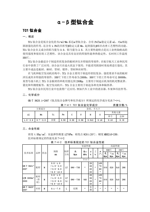
α-β型钛合金TC1钛合金一、概述TC1钛合金是低合金化的Ti-Al-Mn系近α型钛合金,含有2%的α稳定元素Al,对α相起固溶强化的作用。
还含有1.5%的共析型β稳定元素Mn,起到强化β相并改善工艺塑性的功能。
TC1钛合金名义成分的铝当量为3.0,钼当量为2.5,其主要性能特点是比工业纯钛略高的使用强度和很好的工艺塑性。
该合金还具有良好的焊接性能和热稳定性,长时间工作温度350℃。
TC1钛合金最适合于制造形状复杂的板材冲压并焊接的零部件,在航空航天工业和民用行业中获得了广泛应用。
该合金只在退火状态下使用,不能采用固溶时效处理进行强化,其主要半成品是板材、棒材、管材、锻件、型材和丝材等。
在飞机和航空发动机结构中,TC1合金主要用于制造形状较复杂、强度要求不高的板材冲压成形并焊接的零部件。
350℃下的工作寿命为2000h,300℃下的工作寿命可达30000h。
某型号战斗机上TC1合金板材的单机用量达到230Kg,主要用于制造后机身的机尾整流罩、蒙皮和外侧壁板等。
航空发动机中,TC1合金主要用于制造各种壳体和隔热罩。
TC1钛合金在民用行业中也获得广泛应用,例如汽车工业中的消音器、车架和吊挂件等。
二、化学成分GB/T 3620.1-2007《钛及钛合金牌号和化学成分》所规定的化学成分见表7-4-1。
三、合金性能密度4.55g/cm3,室温弹性模量127GPa,相变点920±20℃,硬度HBS210-250。
技术标准规定的性能见表7-4-2表7-4-2 技术标准规定的TC1钛合金性能TC4钛合金一、概述TC4(Ti-6Al-4V)钛合金是世界上开发最早、应用最广的钛合金。
它的产量约占全世界各种钛合金半成品总产量的一半以上,在航空航天工业中超过80%。
Al通过固溶强化α相提高合金的室温强度和热强性能,而V既提高强度又改善塑性。
V还能抑制α2超结构相的形成,避免在长时间使用过程中出现合金脆化。
TC4钛合金的主要特点是优异的综合性能和良好的工艺特性。
tc4钛合金板材锻造镦拔计算《关于tc4钛合金板材锻造镦拔计算》哎呀,说起tc4钛合金板材锻造镦拔计算这事儿啊,可真是让我有一肚子话想说呢。
我记得有一次啊,我在我们那个小工厂里,亲眼看到师傅们在搞这个tc4钛合金板材的锻造。
那场面,真的是特别热闹又有点让人摸不着头脑。
当时啊,那一块块的tc4钛合金板材就摆在那儿,看起来就和普通的金属板材有点不一样,它泛着一种独特的光泽,有点暗暗的,但是又感觉很有质感。
师傅们要开始锻造镦拔了,我就在旁边瞅着。
首先就是要计算啊,这个计算可不像咱们算个一加一那么简单。
师傅拿着个小本子,上面密密麻麻地记着各种数据。
我凑过去看,就看到好多我都看不懂的符号和数字。
师傅说,这tc4钛合金板材锻造镦拔的计算啊,得考虑它的原始尺寸,比如说板材的长、宽、厚,这每一个数据都得精确得很呢。
就像那块板材,长大概是50厘米,宽20厘米,厚3厘米,这些数字就像是这个板材的身份证一样重要。
然后啊,还要考虑它的材质特性。
师傅说,tc4钛合金这东西可娇贵了,它的强度、韧性啥的都和计算有关系。
他指着板材的一个小角落跟我说:“你看,这地方要是计算不好,锻造的时候就可能出问题,可能会这儿裂了或者那儿变形过度了。
”我仔细瞧了瞧,那小角落看起来和平常的地方也没啥区别啊,但是师傅这么一说,我就知道这里面的门道深着呢。
师傅开始计算锻造比了,这又是一个复杂的东西。
他一边在本子上写写画画,一边嘴里还嘟囔着。
我就听到他说什么“这个锻造比要根据之前的经验公式来算,但是又不能完全照着来,还得看实际的板材情况。
”我当时就想,这可真够麻烦的。
师傅计算的时候,那个认真的样子啊,眼睛都快贴到本子上了,眉头皱得紧紧的,就像在解一道世界上最难的谜题。
接下来就是镦拔的计算了。
这镦拔到底怎么个算法呢?师傅说,得根据要达到的最终形状和尺寸来反推每一步的操作数据。
比如说,要把这块板材镦粗多少,拔长多少,这中间的比例关系可讲究了。
我看到师傅拿了个小尺子,在板材上比划来比划去的,好像是在模拟镦拔后的样子。
tc4对核磁共振
TC4(四碳烯铌)是一种含铌的金属有机化合物,其核磁共振(NMR)是指在核磁共振实验中,对TC4样品进行测量和分析。
核磁共振是一种基于原子核的特定频率吸收和发射能量的物理现象。
在核磁共振实验中,样品被放置在磁场中,并通过向样品施加特定频率的射频脉冲来激发样品中的原子核。
激发后,样品中的原子核会通过发射特定频率的能量回到基态,这个过程被称为共振。
通过测量样品吸收和发射能量的频率和强度,可以获取关于样品结构和性质的信息。
对于TC4样品的核磁共振实验,可以用来研究和分析该化合物的结构、化学环境和相互作用等信息。
摘要自20世纪50年代以来,钛及钛合金经历了半个多世纪的发展,种类从最初的Ti-6AI-4V发展到数百种,我国列入国家标准的钛及钛合金牌号就达24种。
由于它强度小、耐热性好、抗腐蚀性优良,它在航空航天、军事、体育器械、医疗器械、照相器材等领域得到了广泛的应用。
但钛合金制造工艺复杂,所以如何改进钛合金的加工工艺,就成为钛合金应用的研究课题。
在钛金的切削加工方面,一些发达国家走在了世界的前列。
为此,研究钛合金的切削加工十分必要,对我国在这方面的发展具有重要的意义。
本文从钛合金的性能、切削特点和车削加工理论出发,分析了TC4车削加工时刀具选择、切削用量、刀具角度选择以及切削力,并从设计试验方案出发,利用切削力测试系统对TC4进行车削力测定,研究切削力曲线特征,建立TC4的切削力经验公式。
关键词:钛合金;刀具选择;切削加工型;正交试验法;经验公式AbstractSince the 1950s, the development of titanium and titanium alloy already experience more than half a century of course, titanium alloy types already from Ti-6AI -4V development to hundreds of kinds, our country listed in the national standard grades of titanium and titanium alloy formule 24. Because of its high strength, low density, good heat resistance, corrosion resistance, excellent in aerospace and military, sports equipment, medical equipment, photographic equipment, etc widely used. Although the broad application of titanium alloys, but the complexity of manufacturing process, so how to improve the processing of titanium alloys , titanium alloys have become the application of research. Machining in titanium alloys, the number of developed countries have been at the forefront of world. To this end, the study of machining titanium alloys is essential to our development in this area is of great significance.In this paper, the performance of titanium alloy, the cutting characteristics and turning theory, and analysis tool TC4 choice when turning, cutting, cutting tool selection and cutting force angle, and the design of orthogonal pilot program, the use of cutting force testing system to TC4 determination of cutting force to study the characteristics of the cutting force curve, the establishment of TC4 empirical formula of force.Keywords: Titanium alloy; tools selection; cutting workability; orthogonal experiment; experience formula1 钛合金概述钛在地球蕴藏着的元素中含量排名第九,其蕴藏量占0.44%到0.57%,1795年德国化学家M.H.克拉普鲁斯发现了该元素并以希腊神Titans命名。