案例分享:这个公司合理避税了80%!
- 格式:docx
- 大小:20.14 KB
- 文档页数:2
Masterpact MT低压空气断路器和负荷开关简化目录早期的 Masterpact 产品设立了世界范围空气断路器的新标准,多年后,许多制造厂也开发具有 Masterpact 革新特点如分断原理,模块化设计和复合材料的产品。
今天,施耐德电气又推出最新的 Masterpact MT 新产品,除了具有传统断路器特点之外 (抽出式,选择性和低维护性),它们又具有了体积优化,内置通讯和测量功能。
Masterpact MT 采用最新技术,增强了产品性能和安全性,是具有容易安装、用户界面友好、操作方便、设计容易的划时代产品。
Masterpact MT系列断路器已通过中国3C 认证及船级社认证。
56E 58880出色源于个性新型 M a s t e r p a c tMasterpact MT 七种分断类型N1 - 标准型,适用于分断低等级短路电流N2 - 适用于一般的应用场合H1 - 适用于分断工业环境的高等级短路电流或两台变压器并联运行的电气系统中H1b - 适用于短路电流较大的工业行业H2 - 高性能型,适用于可能产生非常高短路电流的重工业领域H3 - 适用于既需要高性能的分断能力,又需要高水平配合的场合L1 - 具有高限流能力,用以保护馈电单元或当变压器额定功率提高时,提高开关柜的性能水平易集成于通信网Masterpact MT 可集成于一般管理系统中,优化设备的操作和维护。
通信结构是开放式的。
通过接口可适用于任何协议。
负荷开关负荷开关直接由断路器派生出来的,具有高质量和高性能的特点。
根据型号,负荷开关有 3 种 HA 、NA 和 HF 。
HF 安装了瞬时保护装置,防止短路时合闸。
一旦合闸,负荷开关不再提供保护与普通开关一样。
负荷开关常用于母联上。
特殊应用p 1000V 交流Masterpact NW H10 型断路器和负荷开关,800A 到 4000A, 3 极或 4 极,抽屉式,型号为 H10。
—1—1用途及使用范围2 型号含义及分类2.1 型号及含义2.2 分类2.2.1按安装方式分 a ) 固定式 b ) 抽屉式2.2.2 按极数分:三极、四极2.2.3 按操作方式分 a ) 电动操作b ) 手动操作(检修、维护用)2.3 脱扣器种类智能控制器、欠电压瞬时(或延时)脱扣器、分励脱扣器。
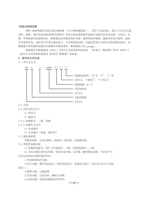
2.4 智能控制器功能RDW2-4000智能型万能式低压断路器 ( 以下简称断路器 ) , 适用于交流50Hz ,额定工作电压交流400V 、690V ,额定电流4000A 的配电网络中,用来分配电能和保护线路及电源设备免受过载、欠电压、短路、单相接地等故障的危害。
断路器具有智能化保护功能,选择性保护精确,能提高供电可靠性,避免不必要的停电。
同时带有开放式通讯接口,可实现四遥功能,以满足控制中心和自动化系统的要求。
该断路器不带智能控制器及传感器可作隔离器用,断路器标示为 。
断路器符合断路器GB 14048.2《低压开关设备和控制设备 第2部分:断路器》和IEC 60947-2《低压开关设备和控制设备 第2部分 断路器》等标准。
a ) 智能控制器分:H 型(多功能型)、M 型(普通智能型)、L 型;b ) 具有过载长延时反时限、短延时反时限、定时限、瞬时脱扣功能。
可由用户自行设定组成所需要的保护特性;c )单相接地保护功能;d )显示功能:整定电流显示、动作电流显示、各线电压显示(电压显示应在订货时提出);e )报警功能:过载报警;f )自检功能:过热自检、微机自诊断;g )试验功能:试验控制器的动作特性。
设计代号万能式断路器壳架等级电流断路器级数:3P 、4P 企业代号安装方式:“C 抽屉式”、“G ”固定式智能脱扣器类型:“M ”型、“H ”、“L ”型2 - 4000 /□ □□ RD W—2—3 正常工作条件和安装条件3.1 周围空气温度上限值不超过+40℃,下限值不低于-5℃,24h 平均值不超过+35℃;上限值超过+40℃或下限值低于-10℃或-25℃的工作条件,用户应与本厂协商。
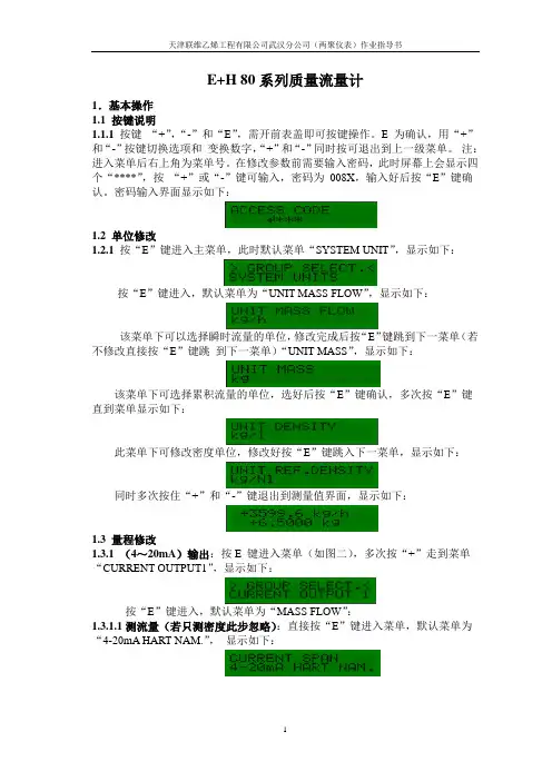
E+H 80系列质量流量计1.基本操作1.1 按键说明1.1.1 按键“+”,“-”和“E”,需开前表盖即可按键操作。
E 为确认,用“+”和“-”按键切换选项和变换数字,“+”和“-”同时按可退出到上一级菜单。
注:进入菜单后右上角为菜单号。
在修改参数前需要输入密码,此时屏幕上会显示四个“****”,按“+”或“-”键可输入,密码为008X,输入好后按“E”键确认。
密码输入界面显示如下:1.2 单位修改1.2.1 按“E”键进入主菜单,此时默认菜单“SYSTEM UNIT”,显示如下:按“E”键进入,默认菜单为“UNIT MASS FLOW”,显示如下:该菜单下可以选择瞬时流量的单位,修改完成后按“E”键跳到下一菜单(若不修改直接按“E”键跳到下一菜单)“UNIT MASS”,显示如下:该菜单下可选择累积流量的单位,选好后按“E”键确认,多次按“E”键直到菜单显示如下:此菜单下可修改密度单位,修改好按“E”键跳入下一菜单,显示如下:同时多次按住“+”和“-”键退出到测量值界面,显示如下:1.3 量程修改1.3.1(4~20mA)输出:按E 键进入菜单(如图二),多次按“+”走到菜单“CURRENT OUTPUT1”,显示如下:按“E”键进入,默认菜单为“MASS FLOW”:1.3.1.1测流量(若只测密度此步忽略):直接按“E”键进入菜单,默认菜单为“4-20mA HART NAM.”,显示如下:按“E”键进入菜单“V ALUE 20mA”,显示如下:此菜单下显示的是最大输出电流代表的物理量大小,修改时注意第一位为符号位,改好后按“E”进入下一步,再“+”和“-”同时按退出到测量值界面如下:1.3.1.2测密度(若只测流量此步忽略):多次按“+”直到显示如下:按“E”键确认并进入下一菜单,默认菜单“4-20mA HART NAM.”,按“E”键进入,默认菜单“V ALUE 0_4mA”,显示如下:此菜单下显示的是最小输出电流代表的密度大小,用“+”或“-”进行修改,改好后按“E”进入菜单“V ALUE 20mA”,显示如下:此菜单下显示的是最大输出电流代表密度的大小,用“+”或“-”进行修改注意,改好后按“E” 进入下一步,再“+”和“-”同时按退出到测量值界面:1.4 空管检测/小信号切除按“E”键进入主菜单,多次按“+”键直到显示为“PROCESSPARAMETER”,显示如下:按“E”键进入菜单,显示如下:选择小信号切除的物理量,默认为“MASS FLOW”,一般不需修改,直接按“E”键进入下一菜单,显示如下:此处修改小信号切除的大小(建议修改为量程的1%~5%),修改完成按“E”进入下一菜单,显示如下:不需要修改,直接按“E”键进入下一菜单,显示如下此处显示的空管检测状态,如需空管检测功能,此选项改成“ON”,如不需要选成“OFF”,然后同时多次按住“+”和“-”键退出到测量值界面(如图七)。
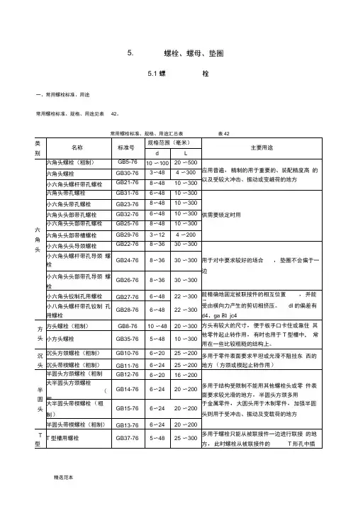
5.螺栓、螺母、垫圈5.1 螺栓一、常用螺栓标准、用途常用螺栓标准、规格、用途见表42。
注:1.冷镦工艺生产的小六角头螺栓具有材料利用率高、生产效率高、机械性能高等优点,但由于头部尺寸较小,不宜用于多次装拆、被联接件强度较低和易锈蚀等场合。
2.当机械性能(强度级别)的分级的规定不能满足使用要求时,可按需要选用材料。
对T型、活节等螺栓的材料在相应标准中有规定。
、六角头螺栓(粗制)(GB5-76)六角头螺栓规格见图20、表43六角头螺栓(粗制)规格(GB5-76)(毫米)表43①为优选系列。
注:1.L0 不包括螺尾,当L W125 时:L0=2d+6 ;当L>125〜200 时:L0=2d+12 ;当L>200 时:L0=2d+25。
2.标记示例:螺栓M10X100GB5 —76表示为直径10毫米,长度100毫米、粗牙普通螺纹,机械性能按5.9级,不经表面处理的六角头螺栓。
三、六角头螺栓精制(GB29 30-76)六角头螺栓(精制)规格见图21、表44六角头螺栓(精制)规格(GB29 30-76)(毫米)表44①为优选系列,其中GB29一76的范围是:d =12以下丄=100以下:GB30 一76的范围是d =10以上丄=16以上。
注:1.L0 不包括螺尾,当L < 125 时:L0=2d+6;当L>125〜200 时丄0=2d+12,当L>200 时:L0=2d+25。
2标记示例:螺栓M10X100GB30 —76。
表示为直径10毫米,长100毫米,机械性能按5.9级,不经表面处理的六角头螺栓。
如螺杆上全部制出螺纹时,应加标记Q,即:螺栓M10X100-Q GB30 一76。
四、沉头螺栓沉头螺栓(粗制)(GB10-76)、沉头带楔螺栓(粗制)(GB11-76)见图22〜23、表45①②为优选系列。
注:1.L0 不包括螺尾,当L W125 时;L0=2d+6;当L>125〜200 时:L0=2d+12;当L>200 时:L0=2d+25。

前挡尺寸A奥迪奥迪TT135*60cm 奥迪A1140*70cm 奥迪A4L145*80cm 奥迪A3140*75cm 奥迪A6L150*75cm 奥迪A5145*80cm 奥迪Q3145*80cm 奥迪Q5150*80cm 奥迪Q5150*80cm 奥迪A8150*75cmB奔驰奔驰B级140*70cmsmart140*70cm奔驰C级140*70cm奔驰E级145*80cm奔驰S级145*80cm奔驰R级150*80cmB宝马宝马MINI135*60cm 宝马3系140*70cm宝马7系150*75cm宝马5系150*75cm宝马1系140*70cm宝马X1145*80cmM3140*75cm1系M145*80cm宝马X3150*80cm宝马6系150*75cm宝马X5150*80cm宝马M系150*75cmM5150*75cm宝马X6150*80cmB宝骏宝骏630140*70cmB北汽骑士150*80cmE系列140*70cm路霸150*80cmB比亚迪比亚迪F3135*60cm 比亚迪F0135*60cm比亚迪G3135*60cm比亚迪G4135*60cm比亚迪F6140*75cm比亚迪G6140*75cm比亚迪L3140*75cm比亚迪M6145*80cm比亚迪S8140*75cm比亚迪E6150*75cm 比亚迪M6145*80cm 速锐140*75cm思锐145*80cm比亚迪S6145*80cm D大众捷达135*60cm 老宝来140*70cm速腾140*70cm新领驭140*70cm桑塔纳140*70cm POLO140*70cm高尔夫6140*75cm 09宝来140*75cm朗逸140*75cm迈腾140*75cmEos140*75cm帕萨特145*80cm途观145*80cm途锐150*80cm夏朗150*80cm途安145*80cm大众CC150*75cm辉腾150*80cm Scirocco尚酷140*70cm D道奇酷威150*80cmD东风风神A60140*75cm 风神H30140*75cm风神S30140*75cm景逸145*80cm景逸SUV150*80cmD东南菱悦135*60cmV5菱致140*75cmF丰田威驰135*60cm 雅力士135*60cm威姿135*60cm锐志140*70cm佳美140*70cm花冠140*70cm凯美瑞140*75cm逸致145*80cm皇冠140*75cm卡罗拉140*75cm普锐斯140*75cm RAV4145*80cm普拉多150*80cm汉兰达150*80cm柯斯达150*80cm红杉150*80cm兰德酷路泽150*80cmG广汽传祺传祺140*75cm传祺GS6150*80cmG广汽吉奥奥轩GX5145*80cm 奥轩G5145*80cmH海马海福星135*60cm丘比特135*60cm王子135*60cm爱尚135*60cm福美来140*70cm普力马140*75cm骑士145*80cmH黄海旗胜V3150*80cmH华泰宝利格150*80cm华泰B11150*75cm圣达菲145*80cmJ江淮同悦140*70cm悦悦140*70cm宾悦140*70cm和悦140*70cm和悦RS140*75cm瑞风145*80cm瑞风II145*80cm瑞鹰150*80cmK凯迪拉克SLS赛威145*80cm 凯迪拉克CTS145*80cm凯迪拉克SRX150*75cm凯雷德ESCALADE150*80cmL铃木雨燕135*60cm新奥拓135*60cm羚羊135*60cm派喜Splash135*60cm浪迪135*60cm北斗星135*60cm天语·尚悦140*75cm利亚纳140*70cm吉姆尼140*70cm天语SX4140*75cm凯泽西145*80cm超级维特拉145*80cmL力帆力帆320135*60cm 力帆520140*75cm力帆620140*75cm力帆X60145*80cm力帆720140*70cmL陆风陆风X5150*80cm 陆风X8150*80cm陆风X6145*80cm陆风X9145*80cmL路虎卫士145*80cm 发现3150*75cm揽胜极光150*75cm第四代发现150*80cm 揽胜150*80cm揽胜运动版150*80cm 神行者2150*80cmL雷诺拉古那140*70cm 风朗Fluence140*75cm 梅甘娜140*75cm科雷傲150*80cm风景145*80cm纬度140*75cm塔利斯曼150*75cmM名爵MG3140*75cmMG7140*70cmMG6140*75cmN纳智捷纳智捷大7150*80cm Q起亚RIO锐欧140*70cm千里马140*70cm远舰140*70cm秀儿140*75cm福瑞迪140*75cm起亚K2140*75cm赛拉图140*70cm速迈140*75cm智跑150*80cm起亚K5140*75cm起亚K3140*75cm狮跑145*80cm欧菲莱斯145*80cm 新佳乐145*80cm索兰托150*80cm嘉华150*75cmVQ150*80cm霸锐150*75cmR日产玛驰140*70cm 逍客140*75cm老骐达140*70cm骏逸140*70cm新阳光140*70cm颐达140*70cm骊威140*75cm骐达140*75cm轩逸140*75cm风度140*75cm蓝鸟140*75cm新天籁140*75cmNV200150*75cm楼兰Murano150*80cm 帕拉丁150*80cm贵士150*80cm途乐150*80cm日产GT-R150*80cmS斯柯达晶锐135*60cm 昕锐140*70cm明锐140*70cm昊锐140*75cmS三菱蓝瑟135*60cm 君阁140*75cm菱帅140*70cm欧蓝德140*75cm帕杰罗速跑140*75cm ASX劲炫(进口)140*75cm 菱绅140*75cm格蓝迪140*75cm戈蓝140*75cm LANCER145*80cm帕杰罗(进口)145*80cm 帕杰罗·劲畅145*80cm X雪铁龙C2135*60cm爱丽舍140*70cm赛纳140*70cm凯旋140*75cm毕加索140*75cmC4140*75cm世嘉140*75cmC5150*75cmC6145*80cm品牌车型最匹配的前挡尺寸B本田锋范140*70cm 理念S1140*70cm思铭140*70cm09飞度两厢140*75cm 思域140*75cm奥德赛140*75cm八代雅阁145*80cm CR-V145*80cm雅阁2.4150*75cm思铂睿150*75cm歌诗图150*75cm思迪150*80cmB别克林荫大道140*70cm 凯越140*70cm英朗GT140*75cm英朗XT140*75cm昂科拉140*75cm荣御145*80cm君威145*80cm新君越150*75cmGL8150*80cm老君越150*80cm昂科雷150*80cmB标致标致207140*75cm 标致206140*75cm标致408145*80cm标致307145*80cm标致308145*80cm标致3008150*80cm标致4008145*80cm标致508150*75cmB奔腾奔腾B50140*70cm 奔腾B70140*70cm奔腾B90140*75cmB保时捷卡宴150*80cm C长城哈弗M2140*75cm 长城酷熊135*60cm哈弗M1135*60cm哈弗M4140*75cm腾翼C20R140*75cm腾翼V80140*75cm长城炫丽140*70cm风骏5140*70cm腾翼C30140*70cm腾翼C50140*70cm哈弗H3145*80cm哈弗H5145*80cm哈弗H6145*80cmC长安S460135*60cm 长安之星135*60cm 欧诺135*60cm奔奔140*70cm志翔140*75cmCX30140*75cm悦翔140*75cm悦翔V3140*75cm悦翔V5140*75cm睿骋150*75cmCX20140*75cmF福特蒙迪欧150*75cm 福克斯140*75cm福特S-MAX145*80cm野马145*80cm新嘉年华140*70cm翼虎145*80cm致胜150*75cm锐界150*80cm探险者150*80cm麦柯斯150*80cmF菲亚特501135*60cm 博悦140*75cm菲翔150*75cm菲跃150*80cmJ 江铃驭胜150*80cmJ 吉普指南者145*80cm 自由客145*80cm牧马人150*80cm大切罗基150*80cm指挥官150*80cmJ吉利豪情135*60cm美日135*60cm美人豹135*60cm优利欧135*60cm全球鹰GC7140*70cm全球鹰GX2135*60cm熊猫135*60cm金刚140*70cm自由舰140*70cm金鹰140*70cm英伦SC3135*60cm英伦SC6135*60cm英伦SC5140*70cm英伦SC7140*70cm帝豪EC7140*75cm英伦TX4140*75cm帝豪EC8140*75cm英伦SX7145*80cm全球鹰GX7145*80cmK克莱斯勒铂锐140*70cm克莱斯勒300C150*75cm大捷龙150*75cmL雷克萨斯雷克萨斯CT140*70cm 雷克萨斯IS140*70cm雷克萨斯ES140*75cm雷克萨斯GS145*80cm雷克萨斯LS145*80cm雷克萨斯GX150*75cm雷克萨斯LX150*75cm雷克萨斯RX150*75cmL莲花莲花L5140*70cm莲花L3140*70cm竞速140*70cm竞悦140*70cmM马自达马自达2140*70cm 马自达6140*70cm马自达3140*70cm睿翼140*75cm马自达5140*75cm马自达3星骋140*75cm马自达8145*80cm马自达CX-5145*80cm 马自达CX-7150*80cm 马自达CX-9150*80cm O讴歌讴歌RL150*75cm 讴歌ILX140*70cm讴歌TL150*75cm讴歌RLX150*75cm讴歌ZDX150*75cm讴歌RDX150*80cm讴歌MDX150*80cmO欧宝安德拉150*80cm 雅特140*70cm英速亚150*75cmQ奇瑞旗云2135*60cm QQ3135*60cm瑞麒X1135*60cm瑞麒M1135*60cm 风云2135*60cmA1135*60cmQQ6135*60cm Qqme135*60cm旗云1135*60cm奇瑞A5140*70cm 旗云3140*75cm旗云5140*70cm瑞虎140*75cm瑞麒G3140*70cm 瑞麒G5140*70cm 东方之子140*75cm 奇瑞A3140*75cm 奇瑞E5145*80cmR荣威荣威350140*75cm荣威750140*70cm荣威550140*75cm荣威950150*75cm荣威W5150*80cmS斯巴鲁力狮145*80cm斯巴鲁XV140*75cm森林人12款以前140*75cm 森林人13款以后145*80cm 翼豹140*75cm驰鹏150*80cm傲虎145*80cmW沃尔沃沃尔沃S40140*70cm 沃尔沃C30140*70cm沃尔沃S80150*75cm沃尔沃C70145*80cm沃尔沃S60150*75cm沃尔沃V60150*75cm沃尔沃S80L150*75cm 沃尔沃XC60150*80cm 沃尔沃XC90150*80cm S现代雅绅特135*60cm 索纳塔8代140*70cm i30140*70cm伊兰特140*70cm瑞纳140*70cm朗动140*70cm悦动140*75cm飞思140*75cmix35145*80cm领翔145*80cm名驭145*80cm途胜145*80cm御翔145*80cm雅尊150*75cm劳恩斯150*75cm劳恩斯酷派150*75cm 新胜达150*75cm维拉克斯150*80cm雅科仕150*75cmX雪佛兰乐驰135*60cm 爱唯欧135*60cm SPARK斯帕可135*60cm 乐风135*60cm乐骋135*60cm景程140*70cm新赛欧140*70cm科鲁兹140*75cm沃蓝达Volt140*75cm爱唯欧140*75cm迈锐宝150*75cm科帕奇150*80cmY一汽欧朗145*80cm森雅M80140*75cm森雅S80135*60cm威志V2140*70cm威志V5140*70cm夏利N7135*60cm夏利N5135*60cmY英菲尼迪英菲尼迪EX145*80cm 英菲尼迪G系140*75cm英菲尼迪M系145*80cm英菲尼迪FX150*80cm英菲尼迪JX150*80cm英菲尼迪QX150*80cmZ中华骏捷140*70cmH530140*70cmH320140*70cmH330140*70cmH230135*60cm中华V5140*75cm酷宝140*75cm尊驰140*75cmZ众泰众泰2008135*60cm 众泰5008135*60cm众泰Z300140*75cm。
LED 指示灯8010 系列使用说明书其他语种 ENFRITESRUNLDKSEFIPTGRPLCZSKHUSLROBGLVLTEECHKRCN –保存以备将来使用!–内容目录2LED 指示灯8010 系列内容目录1总体信息...............................................................................................................31.1制造商..................................................................................................................31.2关于本使用说明书................................................................................................31.3其他文档...............................................................................................................31.4标准和规定的符合性.............................................................................................32符号说明...............................................................................................................42.1本使用说明书中的符号.........................................................................................42.2设备上的符号.......................................................................................................43安全......................................................................................................................53.1设计用途...............................................................................................................53.2人员资格...............................................................................................................53.3残余风险...............................................................................................................64运输和仓储...........................................................................................................75安装与装配...........................................................................................................75.1安装/拆卸............................................................................................................75.2装配......................................................................................................................76调试......................................................................................................................87运行......................................................................................................................88维护、保养、修理................................................................................................98.1维护......................................................................................................................98.2保养......................................................................................................................98.3修理......................................................................................................................99退回......................................................................................................................910清洁......................................................................................................................911废弃物处置.........................................................................................................1012配件和备件.........................................................................................................1013附录A................................................................................................................1013.1技术数据.............................................................................................................1014附录B................................................................................................................1314.1尺寸信息/固定尺寸 (13)301668 / 80106223002022-01-26·BA00·III·zh·02总体信息3LED 指示灯8010 系列1总体信息1.1制造商1.2关于本使用说明书▶在使用前必须认真阅读本使用说明书、尤其是安全提示。
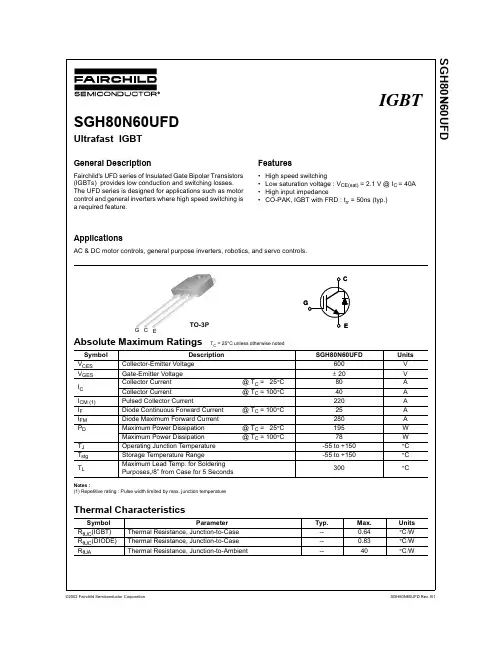
Electrical Characteristics of DIODE TC = 25°C unless otherwise notedCES CE CES GEI GES G-E Leakage Current V GE = V GES, V CE = 0V ----± 100nAOn CharacteristicsV GE(th)G-E Threshold Voltage I C = 40mA, V CE = V GE 3.5 4.5 6.5VV CE(sat)Collector to EmitterSaturation VoltageI C = 40A, V GE = 15V-- 2.1 2.6VI C = 80A, V GE = 15V-- 2.6--VDynamic CharacteristicsC ies Input CapacitanceV CE = 30V, V GE = 0V,f = 1MHz --2790--pFC oes Output Capacitance--350--pF C res Reverse Transfer Capacitance--100--pFSwitching Characteristicst d(on)Turn-On Delay TimeV CC = 300 V, I C = 40A,R G = 5Ω, V GE = 15V,Inductive Load, T C = 25°C --23--nst r Rise Time--50--ns t d(off)Turn-Off Delay Time--90130ns t f Fall Time--50150ns E on Turn-On Switching Loss--570--uJ E off Turn-Off Switching Loss--590--uJ E ts TotalSwitchingLoss--11601500uJt d(on)Turn-On Delay TimeV CC = 300 V, I C = 40A,R G = 5Ω, V GE = 15V,Inductive Load, T C = 125°C --30--nst r Rise Time--55--ns t d(off)Turn-Off Delay Time--150200ns t f Fall Time--160250ns E on Turn-On Switching Loss--630--uJ E off Turn-Off Switching Loss--940--uJ E ts TotalSwitchingLoss--15802000uJQ g Total Gate ChargeV CE = 300 V, I C = 40A,V GE = 15V --175250nCQ ge Gate-Emitter Charge--2540nC Q gc Gate-Collector Charge--6090nC L e Internal Emitter Inductance Measured 5mm from PKG--14--nHSymbol Parameter Test Conditions Min.Typ.Max.UnitsV FM Diode Forward Voltage I F = 25A T C = 25°C-- 1.4 1.7V T C = 100°C-- 1.3--t rr Diode Reverse Recovery TimeI F = 25A,di/dt = 200A/us T C = 25°C--5095ns T C = 100°C--105--I rr Diode Peak Reverse RecoveryCurrentT C = 25°C-- 4.510AT C = 100°C--8.5--Q rr Diode Reverse Recovery Charge T C = 25°C--112375nC T C = 100°C--420--DISCLAIMERFAIRCHILD SEMICONDUCTOR RESERVES THE RIGHT TO MAKE CHANGES WITHOUT FURTHER NOTICE TO ANY PRODUCTS HEREIN TO IMPROVE RELIABILITY , FUNCTION OR DESIGN. FAIRCHILD DOES NOT ASSUME ANY LIABILITY ARISING OUT OF THE APPLICATION OR USE OF ANY PRODUCT OR CIRCUIT DESCRIBED HEREIN; NEITHER DOES IT CONVEY ANY LICENSE UNDER ITS PATENT RIGHTS, NOR THE RIGHTS OF OTHERS.TRADEMARKSThe following are registered and unregistered trademarks Fairchild Semiconductor owns or is authorized to use and is not intended to be an exhaustive list of all such trademarks.LIFE SUPPORT POLICYFAIRCHILD S PRODUCTS ARE NOT AUTHORIZED FOR USE AS CRITICAL COMPONENTS IN LIFE SUPPORTDEVICES OR SYSTEMS WITHOUT THE EXPRESS WRITTEN APPROVAL OF FAIRCHILD SEMICONDUCTOR CORPORATION.As used herein:1. Life support devices or systems are devices orsystems which, (a) are intended for surgical implant intothe body, or (b) support or sustain life, or (c) whosefailure to perform when properly used in accordancewith instructions for use provided in the labeling, can be reasonably expected to result in significant injury to the user.2. A critical component is any component of a life support device or system whose failure to perform can be reasonably expected to cause the failure of the life support device or system, or to affect its safety or effectiveness.PRODUCT STATUS DEFINITIONS Definition of Terms Datasheet Identification Product Status DefinitionAdvance InformationPreliminaryNo Identification Needed Obsolete This datasheet contains the design specifications for product development. Specifications may change in any manner without notice.This datasheet contains preliminary data, andsupplementary data will be published at a later date.Fairchild Semiconductor reserves the right to make changes at any time without notice in order to improve design.This datasheet contains final specifications. Fairchild Semiconductor reserves the right to make changes at any time without notice in order to improve design.This datasheet contains specifications on a product that has been discontinued by Fairchild semiconductor.The datasheet is printed for reference information only.Formative or In Design First ProductionFull ProductionNot In ProductionImpliedDisconnect ISOPLANARLittleFETMicroFETMicroPakMICROWIREMSXMSXProOCXOCXProOPTOLOGIC âOPTOPLANARFACT FACT Quiet Series FAST âFASTr FRFET GlobalOptoisolator GTO HiSeCI 2CRev. I1ACEx ActiveArray Bottomless CoolFET CROSSVOLT DOME EcoSPARK E 2CMOS TM EnSigna TMPACMANPOP Power247 PowerTrench âQFET QS QT Optoelectronics Quiet Series RapidConfigure RapidConnect SILENT SWITCHER âSMART START SPMStealthSuperSOT -3SuperSOT -6SuperSOT -8SyncFET TinyLogic TruTranslation UHC UltraFET âVCXAcross the board. Around the world. The Power FranchiseProgrammable Active Droop。
股票编写基础函数1)今收盘对于N日内最低收盘价的涨幅(%)(c-llv(c,n))/llv(c,n)*100;2)今收盘价对于N日最高收盘价的跌幅(%)(HHV(C,N)-C)/HHV(C,N)*100;3)股价在过去N日内运行空间的相对位置(C-LLV(L,N))/(HHV(H,N)-LLV(L,N))*100;4)股价上方N1%至N2%处的筹码(%)aa:=winner(c+c*n2/100)*100;bb:=winner(c+c*n1/100)*100;aa-bb5)股价下方N1%至N2%处的筹码(%)(winner(c-c*n1/100)-winner(c-c*n2/100))*100;6)收盘价N%处的套牢盘100-(winner(c*N/100))*100;7)收盘价N%处的获利盘winner(c*N/100)*100;8)下影线(MIN(O,C)-L)/L*100;9)上影线(h-max(o,c))/max(o,c)*100;10)本周期的涨跌幅(c-ref(c,1))/ref(c,1)*100;11)振幅(h-l)/l*100;12)均线金叉(M.N为均线周期)cross(ma(c,m),ma(c,n))13)均线多头排列a1:=ma(c,n1);a2:=ma(c,n2);a3:=ma(c,n3);a4:=ma(c,n4);count(a1>a2 and a2>a3 and a3>a4,3);14)均线空头排列a1:=ma(c,n1);a2:=ma(c,n2);a3:=ma(c,n3);a4:=ma(c,n4);count(a1<a2 and a2<a3 and a3<a4,3);15)N日均线向下aa:=ma(c,n);bb:=ref(aa,2);aa<bb16)向前N日至M日出现过均线死叉(P1<P2)aa:=ma(c,p1);bb:=ma(c,p2);cc:=ref(cross(bb,aa),n);count(cc,m);17)今日成交量大于N日以来的均量VOL>MA(VOL,N);18)低位密集A1:=COST(85);A2:=COST(15);A3:=A1-A2;A4:=(A1+A2)/2;A5:=A3/A4*100<10;B1:=HHV(H,120);B2:=LLV(L,120);B3:=B1-B2;B4:=(A4-B2)<B3/2;A5 AND B4;19)换手率VOL/CAPITAL*100;20)N日盈亏V1:=VOL/SUM(VOL,N);V2:=DMA(CLOSE,V1);V3: (CLOSE-V2)/V2*100;21)强势整理{参数M、N分别代表周期和幅度m:1 20 2 n:1 20 5}a1:=abs(close-open)/open<0.015;a2:=count(a1,m)=m;a3:=ref(o,m)<ref(close,m) andref(close,m)/ref(close,m+1)>1+n/100;a2 and a322)高开大阴{参数m,n分别代表幅度m:1 10 4 n:1 20 5}OPEN>CLOSE AND OPEN/REF(C,1) >= 1+M/100 AND CLOSE/OPEN<=1-N/100 23)低开大阳线{参数m,n分别代表幅度m:1 10 4 n:1 20 7}OPEN<CLOSE AND OPEN/REF(C,1) <= 1-M/100 AND CLOSE/OPEN>=1+N/100点符号1、间隔点:20,colorred,pointdot,linethick2;80,colorred,pointdot,linethick2;50,colorred,pointdot,linethick2;2、间隔线20,colorred,linethick2;80,colorred,linethick2;50,colorred,linethick2;3、信号字DRAWTEXT(RSI1<10,RSI1,'买'),Colorlime;DRAWTEXT(RSI1>85,RSI1,'卖'),Colorlime;4、笑哭脸DRAWICON(VR24<25,VR24,1),ColorFF0000;DRAWICON(VR24>350,VR24,2),ColorFF0000;5、一线提示cross("kdj.j"(9,3,3),"kdj.d"(9,3,3)) and "kdj.j"(9,3,3)<20,colorred6、一柱顶天IF(VAR4=50,50,0),stick,linethick2;7、小人作怪多头卒:Var3,LINETHICK2, COLORf00ff0;空头卒:Var4,LINETHICK2, COLORYELLOW;DRAWICON(Var9,Var9,1);DRAWICON(Var10,Var10,2);8、小人买入:Var1 AND Var2,stick,linethick2,colorred;卖出:CROSS(80,Var4),stick,linethick2,colorgreen;drawicon(卖出,1.1,2);drawicon(买入,1.1,1);9、粗细面条LINETHICK2第3,4,6和7,还有8只要把RSI或VR或Var改成所在公式参数就可用;第5cross不能改,其它的可改;9你爱把线设多粗细都行。
Installation manualCard reader Sirius i80L(P)o Producto Installationo Connectiono Technical dataPublicationJanuary 2014,Keyprocessor BVPaasheuvelweg 201105BJ Amsterdam, The NetherlandsTel.: +31-20-4620700This manual represents the knowledge at the above mentioned time. Keyprocessor works non-stop to improve her products. For the most recent technical information please contact your consultant or dealer.Content overviewPublication (2)Content overview (2)1The product (3)1.1Sticker i-serie (3)1.2Spacers (3)1.3Reader configuration (4)1.3.1LEGIC prime programmable (4)2Installation and use (5)2.1Location (5)2.2Mounting instructions (5)2.3Use of the i80L/P (6)3Connection (7)3.1Sirius i80L connector lay-out (7)3.2If door controller Polyx™ (8)3.2.1Direct connection (RS485) (8)3.2.2Connection using an Adapterboard (9)3.3If door controller Orbit (9)3.3.1Connecting with UTP cable (10)3.3.2Connection with CKY 3x2x0,14mm² (10)4Technical data (11)4.1Cable specifications (12)4.1.1Data signal Clock/Data (12)4.1.2Data signal Wiegand (12)4.1.3Data signal RS485 (13)4.2Certificates (14)1The productThe Sirius i-series LEGIC card reader is a versatile card reader which supports the LEGIC card read protocol.This manual provides the necessary information concerning the installation instructions, mounting and use of the card reader which is supplied as standard.The Sirius i-series LEGIC card reader:Sirius i80 L Sirius i80/LP1.1Sticker i-serieOn the back of the card reader a sticker placed.This sticker features a QR code.After scanning this QR code, all necessary informationwill be downloaded automatically.1.2SpacersThe spacer is designed for the following purpose. It can make the card reader more robust for external influences but it can also be useful when installing the Sirius card reader on existing plants.801-6120 Sirius i80L(p) Spacer801-6121 Sirius i80L(p) outside mounting spacer1.3Reader configurationWhen using the Sirius i-serie, the following LEGIC configuration is possible. The configuration is described in the paragraph below.1.3.1LEGIC prime programmablePart number:∙I80L 801-5131∙I80Lp 801-5132Standard communication:④An Polyx based on RS485④An Orbit based on Clock/Data or Wiegand.Output length when using Clock/Data, Wiegand, RS485:④Depending on the card data and programmed settings.Standard LED function④When the reader is provided with power, the LED color is red.④When the LED connection is switched to GND, the LED color is green.Standard IO function:④ A standard configured card reader does not use the extra IO functionality. When thisfunction is needed, you need to order another card reader.Programmable:④The card reader is programmable with the supplied program tool. For more information,see the Sirius program tool manual.2Installation and useBy the use of ferrite, the card reader is insensitive to be installed on a metal surface.2.1Location④Determine the location where the Sirius card reader should be installed. There is amaximum cable length between the reader and door controller.④Exception: using an external power supply, you can increase the achievable distancebetween the door controller and card reader.④Install the reader with a minimum lateral distance of 20 cm from each other.2.2Mounting instructionsMount the card reader preferably on an outletPicture 1: Sirius i80L measurements④Pull the cable through the mounting plate of the Sirius reader.④The screw hole of the card reader should be placed on the underside.④Mount the back plate of the card reader to the outlet, using the existing screws.④When not removed, remove the orange colored film of the Buzzer④Click the front of the card reader at the top of the mounting plate④Attach the front of the card reader to the mounting plate with the supplied 'specialmounting bolts.2.3Use of the i80L/PWhen entering the PIN code, the finger must be released at least 1 cm from the panel before the next digit is entered.3Connection3.1Sirius i80L connector lay-outConnect the cable as shown in this chapterThe reader accepts a supply voltage of 5.0 - 16.0 VDC.A higher input voltage results in a lower power consumption and provide cost-effective wiring with a smaller diameter of the conductor.When using an external power supply, it must comply with the SELV guidelines.3.2 If door controller Polyx ™The Sirius card reader can be connected in two ways with the Polyx ™: directly or by using an AdapterboardFor optimal communication, it is recommended to have the latest version of one of the following operating system∙ 2.6 JFSS2 ∙ 3.3 UbiFS3.2.1 Direct connection (RS485)Recommended cable type between a Polyx and the Sirius card reader is: (4.1 for more information)∙ CAT5 UTP four twisted pairs of 24AWG copper conductors ∙ CAT6 UTP four twisted pairs of 24AWG copper conductorsA direct connection (without using an Adapterboard) between the Sirius card reader and a Polyx™ is NOT possible when:∙ Sirius and Polyx™ are installed in different buildings and thus the connectionleaves the building or ∙ the wiring is no UTP cable (CAT5 or CAT6) or ∙ an existing (non UTP) cable is reused or ∙ overvoltage protection for the card reader is required or ∙ An external power supply is required for the card reader.If any of the above conditions applies, see chapter 3.2.2.Polyx, directly connected to a Sirius card reader:Picture T-568B3.2.2Connection using an AdapterboardRecommended cable type between a Polyx and the Sirius card reader, using an Adapterboard is:∙Shielded cable with twisted pairsIf a direct connection is not possible, an Adapterboard must be placed between Polyx and the Sirius card reader.Adapterboard and Polyx are connected with a default UTP cat5 cable (or higher) (plug connection).Connecting wires as shown in the diagrams below.④Connect GND of the Adapterboard to the local Earth.④Connect the shield of the ground cable to the GND connection of the Adapterboard.Do not place any jumpers! For more information see the Adapterboard manual.Possible connections of the card reader Sirius on the Adapterboard3.3If door controller OrbitRecommended cable type between the Orbit and Sirius card reader:∙CKY 3x2x0,14mm²∙CKY 4x2x0,14mm²∙CAT5 UTP four twisted pairs of 24AWG copper conductors∙CAT6 UTP four twisted pairs of 24AWG copper conductors3.3.1Connecting with UTP cable3.3.2Connection with CKY 3x2x0,14mm²4Technical data4.1 Cable specifications4.1.1Data signal Clock/Data4.1.2 Data signal Wiegand4.1.3Data signal RS4854.2Certificates。
5Monobloc directional control valves HDM18Contents5.1General specifications53 5.2Dimensional data54 5.3Performances curves55 5.4Monobloc bodies56 5.5Adjustable direct acting Relief Valve RV58 5.6Spool charts58 5.7Spool positioners59 5.8Lever styles60 5.9Hydraulic-Pneumatic control ON-OFF62 5.10Pneumatic controls62 5.11Hydraulic Proportional control62 5.12Electro-Hydraulic controls63 5.13Solenoids for pilot electrovalves EHI-EHE65 5.14Electromagnetic controls ON-OFF665.1General specifications5.1.1Weight5.1.2Material specification:Body: High strength cast-iron.Spool: Hardened steel and chrome plated Seals: Buna “N”.5.1.3Standard features:1)Parallel circuit2)Balanced interchangeable spools (providesminimum leakage, smooth operation)3)Wide selection inlets, work ports, and outletsthreaded ports.4)Negative overlapping of the spool.5.1.4Optional features available:1)Open or closed centre positions, 3 or 4 way operations, 3 or 4 position (float position), fullopen centre (motor spool) and other spool options.2)Carry over.3)Series circuit4)Complete lever assembly 5)Wide range of positioners 5.1.5Symbols:P : inlet port T : outlet port A/B : work portsH.P .C.O.: carry-over RV : relief valveP 1T 1: side inlet and outlet ports 3.1.0.2: spool position P: pressure line T : exhaust lineE: centre line (by pass).* For HDM18/3 and HDM18/4 please contact our Sales Department.5.2Dimensional data5.3Performance curvesOil: Shell Tellus T37Temperature: 50° C (120° F)Viscosity: 27 mm 2/sFlow ratel/min bar P r e s s u r e d r o pU.S.G.P .M.PSIP ⇒ Tstd. SpoolsMeteringFlow ratel/minbar P r e s s u r e d r o pU.S.G.P .M.PSIFlow ratel/minbarP r e s s u r e d r o pU.S.G.P .M.PSIA/B ⇒ T P ⇒ A/BStrokeA/B → T 150 bar inches mml/minA/B → T 50 barP → A/B 50 barP → A/B 150 barF l o w r a t eU .S .G .P .M .5.4Monobloc bodies5.4.1Standard circuits: parallel Open centre with P - T - RVType/CodeSAE10M18X1.51/2” BSP SAE10HDM18/1HDM18/21/2” BSP K05200.9442.3005.0K01200.9441.1001.0K05200.9441.3007.0K02200.9441.3006.0K03200.9441.1002.0K01200.9442.1001.0K02200.9442.3004.0K03200.9442.1002.0M18X1.5SAE10M18X1.51/2” BSP SAE101/2” BSP M18X1.5SAE10M18X1.51/2” BSP SAE123/4” BSP M22X1.5K04200.9442.8003.0K04200.9441.8004.0K06200.9442.8004.0K06200.9441.8005.0A/BTPPTRVA/BA1A2B2B1A1B1B2A25.4.2Standard circuits: parallelOpen centre and carry-over with P - T - RV H.P.C.OPTRVH.P .C.O.A/B H.P .C.O.CodeSAE10M18X1.51/2” BSPSAE10HDM18/1HDM18/21/2” BSP K25200.9442.3007.0K21200.9441.1003.0K25200.9441.3009.0K22200.9441.3008.0K23200.9441.1004.0K21200.9442.1003.0K22200.9442.3006.0K23200.9442.1004.0M18X1.5SAE10M18X1.51/2” BSP SAE101/2” BSP M18X1.5SAE10M18X1.51/2” BSP SAE123/4” BSP M22X1.5K24200.9442.8005.0K24200.9441.8006.0K26200.9442.8006.0K26200.9441.8007.0A/BT - HPCOPA1B1A2B2A1A2B2B1Note: Body codes consist of: machined casting, seals, plugs and check valve only. Not to be used for complete valve order.5.4.3Optional circuits: series and tandem Open centre with P - T - RVPTRVA/BType/CodeSAE10M18X1.51/2” BSPSAE10HDM18/1HDM18/21/2” BSP K35200.9442.3008.0K31K35K32K33K31K32K33M18X1.5SAE10M18X1.51/2” BSP SAE101/2” BSP M18X1.5SAE10M18X1.51/2” BSP SAE123/4” BSP M22X1.5K34K34K36K36A/BTPA1A2B2B1A1B1A2B2Note: Body codes consist of: machined casting, seals, plugs and check valve only. Not to be used for complete valve order.For availability of -K- bodies without code please contact our Sales Department.5.5Adjustable direct acting Relief Valve RV06152660(860)150(2100)260(3700)Yellow (YE)Green (GR)Blue (BL)30 - 95(400 - 1300)96 - 210(1300 - 3000)211 - 300(3000 - 4200)Type Std. setting bar (PSI)Spring colourPressure set range(PSI)Relief valve set at 30 l/min (8 U.S.G.P .M.)Fluctuating pressureOperating TimeP e a kPTFlow ratel/minbarP r e s s u r e s e t t i n gU.S.G.P .M.PSI RV32320(4600)Red (RD)301 - 400(4200 - 5700)TPS e t t i n g** The maximum operating pressure for each valve series is indicated in the “T echnical specification” at the first page of each valve section.5.6Spool charts5.7Spool positionersW Initial hand lever position F Hand lever in detent positionfSpring return position of hand leverSpool position corresponds to hand lever positionF (N)= Force in Newton (N) needed to operate the spoolNote: consult factory for different configurations.5.7.1Spool positioners dimensions5.7.2Microswitch controlMicroswitch is operated when the spool is in pos.1Microswitch is operated when the spool is in pos.2Microswitch is operated when the spool is in pos.1and 2The microswitch is supplied only on customer's request.Type 30Type 32Type 345.8Lever styles5.8.1Safety levers5.8.2Remote cable controlCables are assembled on the valve only on request and with an extra charge.Cable200.5441.04002200.5441.04005200.5441.04006200.5441.04007200.5441.04008200.5441.04009Cable length Code 1000 mm 1500 mm 2000 mm 2500 mm 3000 mm 4000 mmSpool KitCode 200.9609.0001.0Optional 200.6772.0048.0Type L142Code 200.7071.2012.0Only for rod remote controlM10X1.55.8.3Cross joystick for dual axis spool controlM12X1.75Type AL010Code 200.7022.3004.0L o =2505.9Hydraulic-Pneumatic control ON-OFF5.10Pneumatic controls5.10.1Pneumatic proportional controlType Code PP 150200.9686.5009.05.11Hydraulic Proportional controlJoystick adjustment diagramTypeCode HP 50200.9686.5019.0O u t l e t p r e s s u r e (b a r )30195Adjustment range: (bar) Min. 5 - Max. 30(PSI) Min. 70 - Max. 4205.12Electro-Hydraulic controls5.12.1Electro-hydraulic control internal pilot version ON-OFF with pressure reducing valvePressure reducing valveVCP Return back pressure valve(T2 = 1/2” BSP) code 200.7874.0157.0(to order separately)n p min= 10 bar(145 PSI)n p max= 15 bar(215 PSI)VCPFor solenoid see chapter 5.13Type Code EHI 263*200.9686.6038.0Mechanical and hydraulic featuresMax pressure on P p port 300 bar (4200 PSI)............Reduced pressure afterpressure reducing valve 10 bar (145 PSI)...............Fixed delivery on P ppilot line 1 l/min (0.26 U.S.G.P .M)......................* EHI 263: special body required.Leakage of pressure reducingvalve (in neutral pos.)100 ml/min ( 6.1 in 3/min ).........Min. suggested filtration 25 micron ....................Operating oil temperature min.-30°C- max. 90°C ........min.-22°F - max 194°F..............................5.12.2Electro-hydraulic controls external pilot version ON-OFF EHE 300Type Inlet section 200.9686.6042.0Description Code EHE 305End section200.9686.6036.0For solenoid see chapter 5.135.12.3Electro-hydraulic control external pilot version ON-OFF with pressure reducing valve on inlet manifold EHE 302Type Inlet section200.9686.6031.0Description Code For solenoid see chapter 5.13Mechanical and hydraulic featuresPilot pressure min.10 bar (140 PSI)....................Pilot pressure max.30 bar (420 PSI)...................Pilot pressure with pressurereducing valve 12 bar (175 PSI).......................Pilot flow to each workingsection 1 l/min (0.26 U.S.G.P .M.).......................Operating oil temperature min.-30°C- max. 90°C ........min.-22°F - max 194°F ..............................Leakage of pressure reducingvalve (in neutral pos.)100 ml/min (6.1 in 3/min)..........Min. suggested filtration 25 micron....................5.13Solenoids for pilot electrovalves EHI-EHED.C.Part number 200.5441.10009 A.C.Part number 200.5441.100125.14Electromagnetic controls ON-OFFEPP 344*Type 12 VDC 200.9686.1179.0EPP 343*Voltage Code 200.9686.1180.024 VDC* special body requaired1556.10”89.53.52”2.13”54592.32”2113231.1 / 31 / 2132A=1-3PUSHB=1-2PULLA B++-To be used with special spools only: the spool definition is different from the standard one because of the double “P”. For example A spool become AP3.Ex.: (A spool + 24 VDC positioner)= AP3343Mechanical and hydraulic featuresMax operating pressure 150 bar (2800 PSI)............Max flow 40 l/min (15 U.S.G.P .M.).....................Max back pressure 5 bar (70 PSI).....................Operating oil temperature 80_ C (180_ F)...............Electromagnetic specificationInput tension 12 V DC [24 V DC] ± 10%................Power consumption 60 W ............................ED:100 %.........................................Ohms resistance (cold T _): 2.4 Ω [9.6 Ω]...............Ohms resistance (stabilized T _): 3.1 Ω [12.5 Ω].........Intensity of current (cold T _) 5 A (2.5 A)................Intensity of current (stabilized T _) 3.8 A (1.9 A).........Ambient operating temperature range:-25_C/+60_C ....Average stabilized coil temperature operatedcontinuously +105_C ................................The above mentioned average temperature is obtained with a nominal voltage of 12 V (24 V), with an ambient temperature of 25_ C and with an electromagnet assembled on an hydraulic valve with oil circulation.Insulation class:according to VDE 0580 standard H ...................Electrical connection:with Hirschmann connector per DIN 43650IP 65........E 2022 by Bucher Hydraulics S.p.A., IT - 42124 Reggio ****************************All rights reserved.Data is provided for the purpose of product description only, and must not be considered as warranted characteristics in the legal sense. The information does not relieve users from the duty of conducting their own evaluations and tests. Because the products are subject to continual improvement, we reserve the right to amend the product specifications contained in this catalogue. Classification: 430.300.000。
北京一二科技有限公司电力智能终端系列使用说明书电力智能终端系列ER-LH系列零序电流互感器使用说明书北京一二科技有限公司北京市海淀区上地信息路1# (国际科技创业园)2#楼1102 电话:010 - 8289 3855 • 8289 3856 传真:010 - 8289 3556邮政编码:100 085网址:版权所有2004ERS10.100 003.01重要提示:版权本使用说明书包含的所有内容均受版权法的保护,未经北京一二科技有限公司的书面授权,任何组织和个人不得以任何形式或手段对整个说明书或其部分内容进行复制和转载。
商标二科技有限公司的商标和徽标,本说明书中提及到的其它商标和徽标由拥有该商标和徽标的机构所有,一二科技并无拥有其它商标或徽标的权利。
目录1. 概述 (1)2. 型号说明 (1)3. 使用条件 (1)4. 技术参数 (1)5. 安装 (1)6. 定制 (2)7. 订货须知 (2)8.附录 (3)ER-LH系列零序电流互感器(高灵敏度)参数表 (3)ER-LH系列零序电流互感器(高精度)参数表 (4)ER-LH XX Y系列圆形零序电流互感器参数表 (8)ER-LH系列零序电流互感器选型参考 (8)ER-LH系列零序电流互感器重量参考 (8)ER-LH 系列零序电流互感器说明书ERS10.100 003.0111 . 概述北京一二科技有限公司是北京市高新技术企业,有多年零序电流互感器的专业生产经验,产品质量优于国标GB1208-1997《电流互感器》,并通过了电力工业部电气设备质量检测中心型式试验。
产品已广泛用于电力、冶金、化工、煤炭、建材等行业,并有大量产品出口。
ER-LH 系列零序电流互感器(电缆型)有各种容量、变比、准确级、准确限值系数的高精度零序电流互感器,还有与小电流接地选线等装置、各种继电器等配套的高灵敏度零序电流互感器,分一体式和组合式两类。
采用ABS 工程塑料外壳、树脂浇注而成,具有全密封、绝缘性能好、外形美观、灵敏度高、线性度好、运行可靠、安装方便等特点,规格品种多,适应各种继电器、各种装置的需要,也适应电力系统各种运行方式(中性点接地、中性点不接地、大电阻接地、小电阻接地、消弧线圈接地)的需要。
®1/11Table 1: Main FeaturesDESCRIPTIONAvailable either in through-hole or surface-mount packages, the BTA08, BTB08 and T8 triac series is suitable for general purpose AC switching. They can be used as an ON/OFF function in applica-tions such as static relays, heating regulation, in-duction motor starting circuits... or for phase control operation in light dimmers, motor speed controllers,...The snubberless versions (BTA/BTB...W and T8series) are specially recommended for use on inductive loads, thanks to their high commutation performances.Logic level versions are designed to interface directly with low power drivers such as microcontrollers.By using an internal ceramic pad, the BTA series provides voltage insulated tab (rated at 2500V RMS ) complying with UL standards (file ref.:E81734).Symbol Value Unit I T(RMS)8A V DRM /V RRM 600 and 800V I GT (Q 1)5 to 50mABTA08, BTB08 and T8 Series8A TRIAC SREV. 6February 2006SNUBBERLESS™, LOGIC LEVEL & STANDARDTable 2: Order CodesPart Number Marking BTA08-xxxxxRG See page table 8 onpage 10BTB08-xxxxxRG T8xx-xxxG T8xx-xxxH T8xx-xxxBBTA08, BTB08 and T8 Series2/11Table 3: Absolute Maximum Ratings Tables 4: Electrical Characteristics (T j = 25°C, unless otherwise specified)■SNUBBERLESS and Logic Level (3 quadrants)Symbol ParameterValue Unit I T(RMS)RMS on-state current (full sine wave)IPAK/D 2PAK/DPAK/TO-220AB T c = 110°C 8ATO-220AB Ins.T c = 100°C I TSM Non repetitive surge peak on-state current (full cycle, T j initial = 25°C) F = 50 Hz t = 20 ms 80A F = 60 Hz t = 16.7 ms84I ²t I ²t Value for fusingt p = 10 ms 36A ²s dI/dt Critical rate of rise of on-state cur-rent I G = 2 x I GT , t r ≤ 100 ns F = 120 Hz T j = 125°C 50A/µs I GM Peak gate currentt p = 20 µsT j = 125°C 4A P G(AV)Average gate power dissipation T j = 125°C1W T stg T jStorage junction temperature rangeOperating junction temperature range- 40 to + 150- 40 to + 125°CSymbol Test ConditionsQuad-rantT8BTA08 / BTB08Unit T810T835TW SW CW BW I GT (1)V D = 12 V R L = 30 ΩI - II -III MAX.10355103550mA V GT I - II - III MAX.1.3V V GD V D = V DRM R L = 3.3 k ΩT j = 125°C I - II - IIIMIN.0.2V I H (2)I T = 100 mA MAX.153510153550mA I L I G = 1.2 I GTI - III MAX.255010255070mAII306015306080dV/dt (2)V D = 67 %V DRM gate open T j = 125°CMIN.4040020404001000V/µs (dI/dt)c (2)(dV/dt)c = 0.1 V/µs T j = 125°CMIN.5.4- 3.5 5.4--A/ms(dV/dt)c = 10 V/µs T j = 125°C2.8- 1.5 2.98--Without snubber T j = 125°C- 4.5-- 4.57BTA08, BTB08 and T8 Series3/11■Standard (4 quadrants)Table 5: Static Characteristics Table 6: Thermal resistance Symbol Test ConditionsQuadrant BTA08 / BTB08Unit C B I GT (1)V D = 12 V R L = 30 ΩI - II - III IV MAX.255050100mA V GT ALL MAX. 1.3V V GD V D = V DRM R L = 3.3 k Ω T j = 125°C ALLMIN.0.2V I H (2)I T = 500 mA MAX.2550mA I L I G = 1.2 I GTI - III - IVMAX.4050mA II80100dV/dt (2)V D = 67 %V DRM gate open T j = 125°CMIN.200400V/µs (dV/dt)c (2)(dI/dt)c = 5.3 A/ms T j = 125°C MIN.510V/µsSymbol Test ConditionsValueUnit V T (2)I TM = 11 A t p = 380 µs T j = 25°C MAX. 1.55V V to (2)Threshold voltage T j = 125°C MAX.0.85V R d (2)Dynamic resistance T j = 125°C MAX.50m ΩI DRM I RRMV DRM = V RRMT j = 25°C MAX.5µA T j = 125°C1mANote 1: minimum I GT is guaranted at 5% of I GT max.Note 2: for both polarities of A2 referenced to A1.Symbol ParameterValue Unit R th(j-c)Junction to case (AC)IPAK / D 2PAK / DPAK / TO-220AB 1.6°C/WTO-220AB Insulated 2.5R th(j-a)Junction to ambientS = 1 cm ²D 2PAK 45°C/WS = 0.5 cm ²DPAK70TO-220AB / TO-220AB Insulated 60IPAK100S = Copper surface under tab.BTA08, BTB08 and T8 Series4/11Figure 1: Maximum power dissipation versus RMS on-state current (full cycle)Figure 2: RMS on-state current versus case temperature (full cycle)Figure 3: RMS on-state current versus ambient temperature (printed circuit board FR4, copper thickness: 35µm) (full cycle)Figure 4: Relative variation of thermal impedance versus pulse durationFigure 5: On-state characteristics (maximum values)Figure 6: Surge peak on-state current versus number of cyclesBTA08, BTB08 and T8 Series5/11Figure 7: Non-repetitive surge peak on-state current for a sinusoidal pulse with width t p < 10 ms and corresponding value of I 2tFigure 8: Relative variation of gate trigger current, holding current and latching current versus junction temperature (typical values)Figure 9: Relative variation of critical rate of decrease of main current versus (dV/dt)c (typical values) (Snubberless & L ogic level types)Figure 10: Relative variation of critical rate of decrease of main current versus (dV/dt)c (typical values) (Standard types)Figure 11: Relative variation of critical rate of decrease of main current versus junction temperatureFigure 12: DPAK and D 2P AK Thermal resistance junction to ambient versus copper surface under tab (printed circuit board FR4, copper thickness:35µm)BTA08, BTB08 and T8 Series6/11Figure 13: Ordering Information Scheme (BTA08 and BTB08 series)Figure 14: Ordering Information Scheme (T8 series)Table 7: Product SelectorPart NumberVoltage (xxx)Sensitivity Type Package 600 V 800 V BTA/BTB08-xxxB X X 50 mA Standard TO-220AB BTA/BTB08-xxxBW X X 50 mA Snubberless TO-220AB BTA/BTB08-xxxC X X 25 mAStandard TO-220AB BTA/BTB08-xxxCW X X 35 mA Snubberless TO-220AB BTA/BTB08-xxxSW X X 10 mA Logic level TO-220AB BTA/BTB08-xxxTW X X 5 mA Logic Level TO-220AB T810-xxxG X X 10 mA Logic Level D2PAK T810-xxxH X X 10 mA Logic Level IPAK T835-xxxB X X 35 mA Snubberless DPAK T835-xxxG X X 35 mA Snubberless D 2PAK T835-xxxHXX35 mASnubberlessIPAKBTB: non insulated TO-220AB packageBTA08, BTB08 and T8 Series Figure 15: D2PAK Package Mechanical DataFigure 16: D2PAK Foot Print Dimensions(in millimeters)7/11BTA08, BTB08 and T8 SeriesFigure 17: DPAK Package Mechanical DataFigure 18: DPAK Foot Print Dimensions (in millimeters)8/11BTA08, BTB08 and T8 Series9/11BTA08, BTB08 and T8 Series10/11In order to meet environmental requirements, ST offers these devices in ECOPACK® packages. These packages have a Lead-free second level interconnect . The category of second level interconnect is marked on the package and on the inner box label, in compliance with JEDEC Standard JESD97. The maximum ratings related to soldering conditions are also marked on the inner box label. ECOPACK is an ST trademark. ECOPACK specifications are available at: .Table 8: Ordering InformationOrdering type Marking Package Weight Base qtyDelivery modeBTA/BTB08-xxxyzRGBTA/BTB08-xxxyzTO-220AB 2.3 g 50Tube T8yy-xxxG T8yyxx D 2PAK 1.5 g 50Tube T8yy-xxxG-TR T8yyxx 1000Tape & reel T8yy-xxxB T8yyxx DPAK 0.3 g 75Tube T8yy-xxxB-TR T8yyxx 2500Tape & reel T8yy-xxxHT8yyxxIPAK0.4 g75TubeNote: xxx = voltage, yy = sensitivity, z = typeTable 9: Revision HistoryDate Revision Description of ChangesApr-20025A Last update.13-Feb-20066TO-220AB delivery mode changed from bulk to tube.ECOPACK statement added.元器件交易网BTA08, BTB08 and T8 Series Information furnished is believed to be accurate and reliable. However, STMicroelectronics assumes no responsibility for the consequencesof use of such information nor for any infringement of patents or other rights of third parties which may result from its use. No license is grantedby implication or otherwise under any patent or patent rights of STMicroelectronics. Specifications mentioned in this publication are subjectto change without notice. This publication supersedes and replaces all information previously supplied. STMicroelectronics products are notauthorized for use as critical components in life support devices or systems without express written approval of STMicroelectronics.The ST logo is a registered trademark of STMicroelectronics.All other names are the property of their respective owners© 2006 STMicroelectronics - All rights reservedSTMicroelectronics group of companiesAustralia - Belgium - Brazil - Canada - China - Czech Republic - Finland - France - Germany - Hong Kong - India - Israel - Italy - Japan - Malaysia - Malta - Morocco - Singapore - Spain - Sweden - Switzerland - United Kingdom - United States of America11/11。
XMT7000系列温度控制仪说明书余姚市腾辉温控仪表厂2008 年2 月一、概述XMT7000系列智能温度控制器是一种经济型的智能工业调节仪表,广泛应用于机械、化工、陶瓷、轻工、冶金、石化、热处理等行业的温度、流量、压力、液位等的自动控制系统。
主要特点•热电偶、热电阻、模拟量、频率脉冲等多种信号自由输入,量程自由设置•软件调零调满度,冷端单独测温,放大器自稳零,显示精度优于0.5%FS•模糊理论结合传统PID方法,控制快速平稳,先进的自整定方案•输出可选:继电器触点、逻辑电平、可控硅单相或三相过零和移相触发脉冲、模拟量,另附二路可定义的报警触点输出二、主要技术指标1.输入逻辑电平:DC 0/12V热电偶K E S J T B R N 过零触发脉冲:光偶可控硅输出1A 600V热电阻Pt100 JPt100 Cu50 移相触发脉冲:光偶可控硅输出1A 600V线性信号0-5V 1-5V mV Ω0-10mA电流输出(负荷阻值600Ω以下)0-10mA 0-20mA 4-20mA 0-20mA电流输出(负荷阻值600Ω以下)4-20mA电流输出(负荷阻值600Ω以下)8.控制方式:模糊PID控制、位式控制2.基本误差:输入满量程的±0.5%±1个字9.电源电压:AC85-264V(50/60Hz)3.分辨率:1℃、(额定100-240V AC)4.采样周期:2次/sec 21.6-26.4V AC(额定24V AC)5.报警功能:上限,下限,上偏差,下偏差,21.6-26.4V DC (额定24V DC)区间外,区间内10.工作环境:温度0-50℃,湿度<85%RH的6.报警输出:继电器触点AC250V 3A(阻值)无腐蚀性场合,功耗<5VA7.控制输出:继电器触点AC250V 3A(阻值)11.面板尺寸:80×160,160×80,96×96,三、产品确认请参照下列代码确认送达产品是否与您指定的型号一致。
案例分享:这个公司合理避税了80%!
今年是非常特殊的一年,由于很多企业准备做的业务筹划、经济计划都被打乱了,好在我们度过了那段艰难的日子,我国经济开始回春。
小编,近日来也听到了一个消息,说一个建筑公司通过合理避税,实现了节税80%。
做建筑公司的都很清楚,建筑行业业务多,利润在外人看起来觉得很高,但是实则是利润虚高。
不仅是因企业所得税、股东分红个税导致税负高,更是没票据!遇到供应商不能开票,导致无法做成本,需要缴纳更多税金等等一系列的问题。
但是有一个建筑公司我自己的公司合理避税了80%,因为该公司不愿透露自己的品牌名,所以小编就把这个公司是怎么节税80%的经验分享给各位,大家仔细阅读下文:
小规模企业节税前,营业额:500万,利润总额:300万,增值税:500万*3.3%=16.5万(包含附加税),企业所得税:300万*25%=75万,个人所得税:(300万-75万)*20%=45万,税收合计:16.5万+75万+45万=136.5万。
小规模企业节税后,营业额:500万,利润总额:300万,增值税:500万*3.3%=16.5万,企业所得税:不需要,个人所得税:500万*1.5%-4.05万=3.45万,税收合计:16.5万+3.45万=19.95万。
原本应该交136.5万,现在只要19.95万,可以说是减少了超过百分之八十以上的税收。
现在易捷税大师就是这么做的,让个人和企业利益最大化,个人所得税低至 1.5%,政府园区代理注册公司记账
报税全托管服务,企业所得税25%全免,我们提供一站式税筹解决方案帮助企业降低80%成本!
建筑行业主要获得企业承包各种项目并提供建筑和安装的收入,所以合理避税应该考虑涉及到各个建筑行业,做到分别设计,筹划出更加详细的建筑税务筹划方案。
不只是建筑行业,更有医疗行业、律师行业、现代服务业等。
如果你想和这个公司一样合理避税80%,但又不太了解相关的税务筹划知识,可以关注,我们会定期更新合理避税干货给大家!。