吉普自由光天电动尾门安装说明书
- 格式:doc
- 大小:8.83 MB
- 文档页数:17

S M A N U As of date of manufacture, meets all ANSI/UL 325 Safety Requirements for Vehicular Garage Door OpenersM A N U A L C A R E F U L L Y B E F O R E I N S T A L A T I O N O R INSTALLER: Place this manual in the plastic envelope provided andpermanently attach to the wall near the pushbutton.Product Features....................................................2 Tools Required/Component Identification.....2 & 3 Assembly Instructions...........................................3 Identify Your Door Type.........................................4 Important Installation Instructions........................5 Installing the Opener..............................................6 Mounting the Front Bracket............................6 Mounting the Power Head...............................7 Using the Manual Release Mechanism...........7 Installation......................................8 Requirements/Permanent Wiring........9 Control and Auxiliary Equipment........................10 Standard Wall Push Button Installation.......10 Installation of the Super Station...................10 Remote Control Radio System .....................11 TABLE OF CONTENTSOR DEATH. Gives instructions to avoid FCC and IC Radio Operation Statement ......12 Installation of Safe Finish Photosystem.......13 Installation Checklist.....................................14 Operation and Adjustment Instructions............15 Important Safety Instructions.......................15 Basic Operating Parameters.........................15 Testing the Limit Settings.............................16 Testing the Sensitivity...................................16 Testing the Reversing System......................16 Testing the Safe Finish Photosystem...........17 Operating the Super Station Wall Station Wiring Diagram.....................................................18 Auxiliary Equipment Wiring Diagram..................19 Troubleshooting Guide........................................19 Warranty Statement. (20)CAUTION READ THESE STATEMENTS CAREFULLY AND FOLLOW THE INSTRUCTIONS CLOSELY The Warning and Caution boxes throughout this manual are there to protect you and your equipment.Pay close attention to these boxes as you follow the manual.WARNING CAUTION Indicates an ELECTRICAL hazard of DAMAGE to the door, door opener, or equipment. Gives instructions to avoid thehazard .Indicates an ELECTRICAL hazard of INJURY OR DEATH. Gives instructions to avoid the hazard . Indicates a MECHANICAL hazard of DAMAGE to the door, door opener, or equipment. Gives instructions to avoid the hazard . Residential Vehicular Garage Door OperatorMODELS: MVP and MVP-SQSTEPLADDER TAPE MEASUREWOOD BLOCKHAMMERHACKSAW TOOLS REQUIRED FOR INSTALLATION1/2” OPEN ENDWRENCHLEVELSCREW DRIVERSMALL SCREW DRIVER (1/8” HEAD)NOTE:Rail/Chain Assembly is packaged separately from the Power Unit. The Inner Trolley half, Front Idler Sprocket, Chain, and Limit Cams are assembled on the Tee Rail at the factory.Follow the steps outlined below to complete assembly prior to installation. Refer to the component identification illustrations on the previous page.STEP 1: Protect the Power Unit cover fromscratching during assembly by placing it on cardboard. Remove the two 5/16"-18 washered nuts and save them for later use. STEP 2: Position the Tee Rail/Chain Assembly box near the Power Unit. Open the box and locate theInstallation Hardware Packet.STEP 3: Locate the Outer Trolley half (packaged 104363ASSEMBLY INSTRUCTIONSDOOR MOUNTINGFRONT IDLERTROLLEY OUTER CHAIN GUARDWALL MOUNTING BRACKETRELEASE ROPE AND KNOBOPENER HARDWAREBAGTEE RAILRUBBER BUMPEROPENER HEAD UNITPHOTOSYSTEM HARDWARERADIO TRANSMITTERCONTROL WIRESPOOLIMPORTANT!IDENTIFY YOUR DOOR TYPE FROM THOSE ILLUSTRATED BELOW ANDFOLLOW INSTRUCTIONS FOR THAT TYPE OF DOORFOR THESE TYPES OF DOORS USE MODEL MVP OR MODEL MVP-SB. USE 7 FT, 8 FT OR 10 FT RAIL (MATCH DOOR HEIGHT)THE MODEL MVP SERIES IN NOT DESIGNED TO OPERATE THESETYPES OF DOORSone 5/16"-18 washered nut (supplied) Tighten the bolt a MAXIMUM of 1.5 turns after the bolt and nut are Recheck the nuts used to secure the TeeRail to the Power Unit, making sure they are tight. the Chain tension, Chain twist, Chain Guard and the position of both the Close Limit Switch and Open Limit Switch Actuators.CHAIN GUARDACTUATORSPROCKETSPROCKET 104366Assembly is now complete and you are ready to begin installation of the opener.CHAINMASTER LINKOUTER NUTINNER NUTMASTER LINKCHAINDOOR TYPE IDENTIFICATIONONE PIECE DOOR NO TRACKJAMB HARDWAREONE PIECE DOOR NO TRACKPIVOT HARDWAREHIGH ARC OF DOOR TRAVELHIGH ARC OF DOOR TRAVELDOORPIVOT104368TRACKTRACKDOORDOOR104367SECTIONAL DOOR CURVED TRACKONE PIECE DOOR HORIZONTAL TRACK JAMB HARDWAREHIGH ARC OF DOOR TRAVELHIGH ARC OF DOOR TRAVELPower Unit on a ladder or other sturdy support.Open the door to the full open position. Allowsection of the door (as shown in the illustration104372Step 8: Connecting the Door Arm to the Door Type 1: Door Mounted BracketVisually align the door arm connecting hole with the middle hole of the door bracket by rotating the tube section in the appropriate direction.Release the trolley (leave door arm attached) with the manual release cord and pull trolley toward the power head unit. Now rotate the door arm tube section two turns counterclockwise (increasing the exposed length of the door rod) to provide a cushion when the door is closed or encounters an obstruction. Align connecting hole in the door arm to middle hole in the door bracket; insert 3/8” diameter bolt and tighten locking nut, allowing for free pivot of the arm. Note: Do not overtighten locking nut as this will cause binding between the door arm and door bracket.Type 2: Strut Mounted BracketVisually align the door arm connecting hole with the connecting pin of the strut by rotating the tube section in the appropriate direction.Release the trolley (leave door arm attached) with the manual release cord and pull trolley toward the power head unit. Now rotate the door arm tube section two turns counter-clockwise (increasing the exposed length of the door rod) to provide a cushion when the door is closed or encounters an obstruction. Align connecting hole in the door arm with the strut mounted connecting bracket. Insert connecting pin through the hole in the door arm. Secure the connecting pin to the strut bracket according to the manufacturer’s instructions. Note: Door Bracket Mount or Strut Mount - If rod bottoms in cushion tube, cut rod to allow for proper function of this assembly. Set the outer trolley to re-engage, see page 7.Alternate StrutConnecting BracketCut to Fit110054-2Openers are subject to vibration during normal operation which may shorten their life spans.Rough Service bulbs, available at most hardware stores, are recommended. Fit Light Diffuser tabs into the panel slots as shown.On most models, theLimit Cams are installed at the factory. If the Limit Cams have not been installed, or it is necessary to move a Limit Cam to a different link, fasten them to the chain as shown at right in the approximate positions as illustrated below. Position theSwitch Actuators as shown below.104380106428FASTENING LIMIT CAM TOCHAINunder “Special Notes” at the While the LED is. The .LED will blink twice to confirm a valid code and Special Notes - Express CodingRepeat the steps listed above as needed or desired for each button. Each button can be programmed to a unique code, however all three buttons may be programmed at one time (Express Coding). To Express Code, select the “+” button in Step 2, then end the code entry in Step 3 with the “+” button (the first 8 entries can be any random code). The code for each button may be changed at any time.However, if the plus button is programmed as described above, it will replace the existing code settings of the zeroStep 1Step 2Step 3used, slide it into the recess provided on the back of the transmitter caseuntil the snaps on the caseHomeLink® is a registered trade mark of Johnson Controls, Inc. This device complies with Part 15 of the FCC Rules and with RSS-210 of Industry Canada. Operation is subject to the following two conditions: (1) This device may not cause harmful interference, and (2) this device must accept anyPRE-POWER ON-INSTALLATION CHECKLISTBefore continuing with the operation andadjustment section, make sure that:1. The front and rear mounts for the opener aresound and secure and the rail is positionedcorrectly above the high arc of the door, and thatthe opener is positioned over the door actioncenterline.2. For sectional door and one piece door withtracks, the position of the door arm (with thedoor closed), is such that it’s connecting point onthe trolley is 5” to 8” behind it’s connectingpoint on the door bracket. The door arm shouldnever be perfectly vertical when the door in inthe closed position.3. The Manual Release Label and cord are secureto the Manual Release Lever. The handle islocated 6 FT above floor level and requires nomore than a 50 pound pull to activate. Thetrolley and the release mechanism are properlylubricated.4. The standard wall push button or the SuperStation (deluxe wall push button station) is insuch a position and of such a height that it canonly be actuated by an adult of average height.The Control Button Warning label isprominently displayed next to the push button orwall station.5. All wiring is correct to codes or better. There isground continuity form the supply. The groundprong on the power cord is intact.6. All ropes have been removed from the door.The door moves freely without binding whenraised or lowered manually. The door iscorrectly balanced and lubricated. All doorhardware is secure and sound. The sensitivityhas been adjusted to minimum force for theapplication.7. The door reverses on obstructions to within 1.5"of the floor. The concrete or other surfacebeneath the closed door provided uniformcontact.8. The plastic envelope for this manual is attachedto the wall near the push button or wall stationand this manual is placed there for owner useand reference.9. On door with extension type counterbalancesprings, restraint cables have been placedthrough the springs.10. There is Ground Fault Interruption (GFI)protection of the power line to the opener or inthe receptacle.11. On doors with adjustable bottom edges, edgeshave been locked after adjustment.TURNING ON POWER TO THE OPENERNOTE: It is now necessary to turn on the power in order to run the opener to test the operation and check the limit settings. Before doing so, ensure that all mounting hardware is installed and has been properly tightened, that all electrical connections are per local code requirements, and that proper wiring practices have been followed. Also, double-check that all ropes have been removed from the door and that the doorway is clear.BASIC OPERATING PARAMETERS Please note the following Operating Parameters which apply to Openers with Auxiliary Entrapment Protection System (Safe Finish™ Photosystem, Installation Instructions on Page 15) and a standard wall push button connected. Please see page 17 for instructions concerning the Super Station Deluxe Wall Push Button operating parameters.IF THE DOOR IS…...FULLY OPEN, then pushing the standard wall Push Button or the radio control will cause the door to begin MOVING DOWNWARD. ...FULLY CLOSED, then pushing the wall Push Button or the radio control will cause the door to begin MOVING UPWARD....MOVING UPWARD, then pushing the wall Push Button will cause the door to STOP. The next push of the wall button will cause the door to begin MOVING DOWNWARD (Alternate Action Operation)....MOVING UPWARD, then pushing the radio control will cause the door to STOP. The next push of the wall button will cause the door to RESUME UPWARD MOVEMENT (Radio Operation). ...MOVING DOWNWARD, then pushing the wall Push Button or the radio control will cause the door to STOP, PAUSE FOR APPROXIMATELY ONE SECOND, AND THEN BEGIN MOVING UPWARD....MOVING DOWNWARD then reaches the down limit, the lamp will blink off for a 1/2 second then turn back on again, remaining on for 4 minutes 30 seconds and will then automatically turn off....MOVING UPWARD then reaches the open limit, the lamp will remain on for 4 minutes 30 seconds and will then automatically turn off.STEP 3: Testing the Sensitivity Force — To test theSensitivity System, start the Opener and grasp the bottom door handle halfway through the door's travel(opening or closing). When testing in the CLOSEdirection, a second person will be needed to maintainpressure on the Push Button IF an Auxiliary EntrapmentProtection Device has not yet been fitted. If a secondperson isunavailable, use astiff cardboard carton placed in the door's downward path to indicate the force the Opener isOPEN FORCEADJUSTMENTCLOSE FORCE ADJUSTMENT104391THE SENSITIVITY SYSTEM REVERSING TESTENSURE THAT THIS IMPORTANT SYSTEMW A R N I N G1 2 3 4 5 6 7 8 9 Plus Button Zero Button Minus ButtonIF DESIRED, RECORD YOUR RADIO TRANSMITTER CODE POSITIONSETTINGS HERESee Page 11 for Radio System programming instructions and FCC/RSS-210 Industry Canada statement. The opener radio system is HomeLink® compatible.Serial #: Date Installed: Your Dealer:This garage door operatorcomplies with all requirements ofANSI/UL Standard 325.P/N 190-111069 Rev. FX1 August 2007Copyright © 2007 Linear LLC。
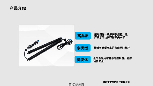

电动尾门原理电动尾门是指车辆尾部的行李厢门可以通过电动装置进行开启和关闭的功能。
电动尾门的原理是基于电动机和控制系统的配合,通过一系列的动力传输和控制装置,实现对尾门的自动操作。
下面将从电动尾门的原理入手,为大家详细介绍电动尾门的工作原理。
首先,电动尾门的核心部件是电动机。
电动机通过电能转化为机械能,驱动尾门的开启和关闭。
电动尾门的电动机通常安装在尾门的底部或侧面,通过传动装置将动力传递给尾门,从而实现尾门的自动运动。
电动机的选用和设计直接影响着电动尾门的性能和可靠性。
其次,电动尾门的控制系统起着至关重要的作用。
控制系统通过传感器感知车主的操作意图和车辆周围环境的情况,对电动尾门的运动进行精准控制。
控制系统还可以实现对电动尾门的速度、力度和停止位置的精确调节,以确保尾门的安全和便捷使用。
除此之外,电动尾门还包括一系列的安全保护装置。
例如,防夹功能可以在尾门关闭过程中,一旦检测到阻力超出设定范围,立即停止尾门的关闭动作,以避免夹伤行人或损坏物品。
此外,还有防夹手功能,当尾门关闭时,如果检测到有手部进入尾门关闭范围,也会自动停止关闭动作,确保行人的安全。
在实际使用中,电动尾门还可以配备一些智能功能,如尾门的高度可调节功能,可以根据车主的身高或停放场景的限制,自动调整尾门的开启高度;还可以通过遥控器、车内按钮或脚部感应器等方式实现对电动尾门的控制,提高了使用的便捷性和舒适性。
总的来说,电动尾门的原理是基于电动机、控制系统和安全保护装置的协同作用,实现对尾门的自动化操作。
它不仅提高了车辆的实用性和舒适性,还为车主带来了更加便捷和安全的使用体验。
随着汽车科技的不断发展,电动尾门的功能和性能也会不断提升,为人们的出行生活带来更多的便利和惊喜。

Preparation:• Disconnect the negative battery terminal. Park the vehicle on level ground and set the emergency brake.• We recommend reading through the installation instructions in whole before performing the work.• Estimated Installation Time: 2 Hours**This installation requires 2 people for best results**You will need the following tools:- Ratchet - 7/16" Socket - 5/32" Allen Wrench/Socket-SharpieK nifeUtility9/16"Wrench --- Drill - 25/64" Drill Bit - 1/4" Drill Bit Included in Kit:18 - Black Button Head Bolt (1/4"-20 x 3/4") 18 - Black Washers (1/4")18 - Rivet Nuts (1/4"-20) 1 - Hex Head Bolt (1/4"-20 x 1 1/4")2 - Flat Washers (1/4") 1 - Hex Nut (3/8"-16) Removal:1. Remove the 8 plastic clips found in each wheel well. (Fig A)Fig A2. Release the 6 push rivets (per side) referenced in (Fig B). Then, pull the inner fender liners out of the vehicle.Fig B3. Release the series of white plastic clips that holds on each rear fender. Then, remove both fenders from the vehicle. (Fig C)Fig C4. Put the inner fender liner back in place on the vehicle. Mark a line out on the inner fender liner that is flush with the body as shown in (Fig D).Fig D5. Hold your fender up to the vehicle to see where the mounting plates start and end. Make a mark at each loca-tion. (Fig E) & (Fig F)Fig EFig F6. At each of the marks you just made, you will go back and make a line extending away from the Jeep body (perpendicular to the body). For the rear-most flap, the line will extend 2" from the Jeep body. Mark around the hump on the liner as shown in (Fig G). Y ou will cut that hump off.Make this line 2 inches longMake a horizontal line that remains2" away from the Jeep's body until youget to the hump on the liner. Then, goaround the hump as shown here.Fig G7. For the middle flap, you will make the rear line 1.5" long and the front line 1" long. About halfway between those lines, make another mark at .5" away from the Jeep body. Then, connect all of those points as shown in (Fig H). Fig H Make this line 1 inch long Make this line 1.5 inches long Make a point .5 inches away from the Jeep body here. Then, connect all of the dots.8. For the front flap, you will make the rear line 1.5" long and the front line 1.75" long. About halfway between those lines, make another mark 1.75" away from the Jeep body. Then, connect all those points as shown in (Fig I). Make this line 1.75 inches longMake this line 1.5 inches long Make a point 1.75 inches away from the Jeep body here. Then, connect all of the dots.Fig I9. Y our fender liner should now look like the one in (Fig J). When you're finished marking out your inner fend-er liner, cut the liner along the line you made.Fig J10. Cut two relief cuts in the front flap on the inner fender liner. Follow the lines shown in (Fig K).11. Fold the flaps on the inner fender liner upward and drill a 1/4" hole anywhere the flap covers the fender mounting holes. (Fig L)Fig K Fig L12. Install a rivet nut into each hole (9 per side) that will be used to mount the fenders. To do this, you will have to drill the holes out with a 25/64" Drill Bit. Then, use the supplied 1/4"-20 x 1 1/4" Bolt (x1), 1/4" Washers (x2), and 3/8"-16 Nut (x1) to make a rivet nut tool as shown in (Fig O). Push a rivet nut all the way into each newly drilled hole. While holding onto the 3/8" Nut with a 9/16" Wrench, fully tighten the 1/4" Bolt (on the Rivet Nut Tool) into the Rivet Nut. Once it is fully tightened, remove the bolt from the rivet nut and move on to the next.Drill Hole Assemble Tool Push RivetNut into Hole Tighten Rivet Nut as ShownFig M13. Hold the fender in place on the vehicle. Then, loosely install the supplied 1/4"-20 x 3/4" Black Bolts (x9) and 1/4" Black Washers (x9) into the newly installed Rivet Nuts. Be sure to sandwich the tabs on your inner fender liner in between the fender and the Jeep body. (Fig P)Fig N14. With all bolts loosely installed, go back and torque the fender mounting bolts to 7 foot pounds.15. Stand back and enjoy your new ADD Rock Fighter™ Fenders.16. Check and re-tighten, if needed, all mounting bolts after 100 miles and periodically thereafter.For Additional Support or Technical Questions,Please Call 480-671-0820 or This product is protected by one or more U.S. patents /patents。
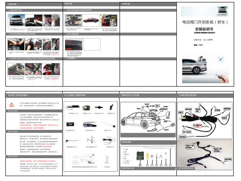
电动尾门系统安装说明书感谢惠购丰田产品*电动尾门系统*这本手册介绍了电动尾门系统的安装方法,安装之前请仔细阅读本手册适用车型2018款汉兰达(两驱精英版、豪华版,四驱精英版、豪华版、骑士版)目录一、安装注意事项 (1)二、构成零件清单 (2)三、安装工具 (2)四、接线概要 (3)五、更换尾门撑杆 (5)六、尾门部分拆装 (7)七、车身部分拆装 (11)八、车身侧走线 (20)九、尾门侧走线 (24)十、线束连接 (26)十一、接线夹使用步骤 (33)十二、安全警示标签粘贴 (34)十三、功能确认 (34)十四、注意 (35)一、安装注意事项承蒙购买电动尾门系统,深表感谢!本说明书叙述电动尾门系统的安装要领。
在安装前,请务必阅读本说明书,以便做到正确安装。
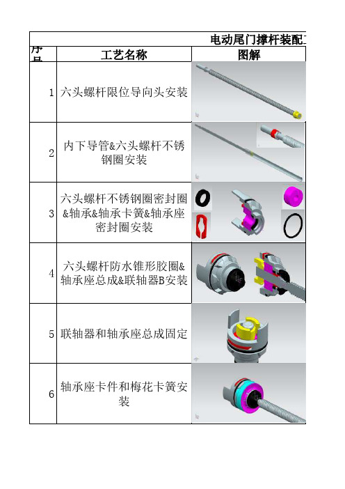
二、构成零件清单三、安装工具电工绝缘胶带套筒扳手、一字螺丝刀、十字螺丝刀、10mm 套筒、14mm 套筒Φ25开口钻美工刀斜口钳尖嘴钳翘板手工电钻四、接线概要1、系统部件流程2、系统线束示意注意:线束安装过程中,接线夹的使用方法在手册第35页查阅。
3、电动尾门COMBOX的安装电动尾门COMBOX的安装位置:如图所示,拆下尾门的内饰板。
找到电动尾门COMBOX安装位置,先将电动尾门COMBOX固定在安装支架上,再用螺栓将电动尾门COMBOX安装至尾上预留的COMBOX安装位置示意图,详细拆装步骤见下文。
4、电动尾门ECU的安装电动尾门ECU的安装位置:如图所示,拆下行李箱左侧的内饰板。
找到行李箱左侧ECU安装位置,先将行李箱左侧ECU固定在安装支架上,再用螺栓将电动尾门ECU安装至行李箱左侧预留的ECU安装位置示意图,详细拆装步骤见下文。
五、更换尾门撑杆1、拆气撑杆1将尾门开到全开状态,并做好支撑;以防止在拆卸气撑杆过程中,尾门向下掉落。
▲不做支撑,可能造成人身伤害!▲为安全起见,需一人支撑尾门,一人更换撑杆,完成两边的气撑杆拆卸后,再更换电撑杆!2用10mm套筒扳手松开气撑杆车身侧支架的两颗固定螺丝并移出。
FREEDOM Mid Height Bed Rack Assembly Instructions 2020 Jeep Gladiator JT with and w/o Tonneau CoverICD Design, LLC is not responsible for any damage that may occur during installation.This is a general assembly manual and may vary by the Gladiator’s versions and options. Please consult our technical department for more information and assistance.This manual is for the Jeep Gladiator with and without the factory sliding bed rail. It contains all the hardware for a no drill and drilling applications. PARTS:✓ 2 Cross Bars✓ 4 Base Legs✓ 4 Base Leg Mounts✓ 2 Side Bars✓ 2 Top Bars✓Hardware:Assembly:32 each. Carriage Bolt 3/8”-16 X 1.0” long, Zinc plated steel, grade 532 each. Lock nut, 3/8”-16, Zinc plated steel, grade 532 each. Flat Washer, 3/8”-16, Zinc plated steel, grade 5Mount Bracket to Base Legs:16 each. Hex Head Bolt 3/8”-16 X 1/2” long, Z inc plated steel, grade 516 each. Lock nut, 3/8”-16, Zinc plated steel, grade 516 each. Flat Washer, 3/8”-16, Zinc plated steel, gradeNote: ** Two extra bolts, nuts and washers for tonneau cover mount optionMounting to Truck Bed:8 each. Hex Head Bolt 3/8”-16 X 1.0” long, Zinc plated steel, grade 58 each. Lock nut, 3/8”-16, Zinc plated steel, grade 58 each. Flat Washer, 3/8”-16, Zinc plated steel, gradeASSEMBLY•Start to assemble the bed rack with all the 32- 3/8” bolts, nut and washers included. It is recommended to assemble the rack upside down on a flat surface.•Assemble as shown in the above diagram.•Align the Base Legs where the two square holes of the Base Leg faces the two square holes on the other Base Leg. The Side Bar will mount to the Base Legs using these square holes.•THERE ARE TWO ROWS OF HOLES ON EACH SIDE OF THE CROSS BAR. Select the outer ones are for the Jeep Gladiator.•Do not tighten the bolts.MOUNTING•Once completely mounted, flip the rack over right side up.•As the rack is heavy when completely assembled, it is recommended to use an extra set of hands for this.•Place the rack on the tray bed.•Position the rack on the tray bed to yourdesired position.•It is recommended in an evenly distributedposition.•Install the 8 3/8” bolts to fix the rack to thebed.•There are three mounting options for thebed rack and will vary with versions with andwithout the factory sliding bed rail. Also,there is the option for a no drill and drillinstallation.•Mounting Option #1: No Drill Installation with Factory Bed Rail System1.Slide in the mount plate bracket with two bolts into the factory rail system (you willneed to remove the end caps to install this plate.2.Line up the mount plate with the Base Legs and install the 3/8”-16 lock nuts andwashers.•Mounting Option #2: Drilling Option1.Align the Bed Rack in the desired position.2.Mark the holes on all four Base Legs on the bed rail lip using the holes on the Base Legsas a template.3.Drill the holes using a 5/16 drill bit for the 3/8”-16 bolts. Ensure that you drill straightthrough the bed rail lip.4.Assemble the bolts with the washers and lock nuts on all four Base Legs.5.This is for versions with and without the factory bed rail system. You can mount the bedrack by drilling even though you have the factory bed rail system. In some cases, youmay have to use your factory rail systems for other gear and accessories and will nothave space for mounting the bed rack.•Mounting Option #3: No Drill Option for versions without the Factory Bed Rail System1.Align the Bed Rack in the desired position.2.Place the clamp bracket behind the bed rail lip and push up until it meets the tray top.3.Install the 3/8”-16 bolts, washers and lock nuts on all four Base Legs and leave loose. Please check the bed rack and the mounting bolts on a regular basis, especially if you are going off the urban path. On a regular basis and especially if you do a lot of off-roading, inspect and tighten any loose bolts.For Technical Support, please call (702) 560-2451 or email: *****************HOBBS is a brand of ICD DESIGN, LLC.2620 Regatta Drive, Suite 102, Las Vegas, Nevada 89128, USATel:(702)560-2451Email:*************************:。
电动尾门(SUV)安装说明书安装产品前请仔细阅读本安装说明书适配车型:智能双杆电动尾门适配18+款大众探歌产品编号:PW029648零件号:5002171版本:A/0电动尾门安装注意事项:1、为了安全和确保产品正常使用,由销售本产品的专业工作人员或经过培训人员安装,切勿私自拆卸本机,以免造成本产品损坏及事故发生;2、装车前的注意事项:1)与客户沟通:咨询车主尾门是否加装过或改装过,如加装尾灯罩/装饰板/音响等使原车尾门增加重量超过2KG,则不能安装该产品;2)启动发动机,检查并确保:汽车各仪表盘针指显示正常及无故障报警,车内门边开关、遥控钥匙按键灵敏并正常使用,尾门开、关状态能在仪表盘上显示等,如发现有异常及时告知客户;3)保持发动机开启一段时间,确保电瓶有电以便保证电动尾门能够运行;4)关闭发动机,检查并确保:汽车内、外表面完好,原车尾门无左右缝隙大小、高低台阶;5)检查并确保该套电动尾门配件清单的种类、数量齐全;6)安装人员取下身上所携带的金属物品等硬物;3、装车中的注意事项:1)拆下的汽车组件一定要保管好,对可能刮花原车的地方采用贴美纹纸、隔珍珠棉等方式进行保护;2)穿线时,防止尾门/原车线束被划破出现短路的潜在风险;连接线路时,连接头一定要做好绝缘并预留一定的活动空间;各部件需固定牢固;3)安装拉线电动尾门的连接档块时,确保能自由活动;4)连线顺序:各部件先连接,再连常电,最后插ECU(先大后小)4、汽车的清洁、整理:1)安装过程留下的杂物及时处理,不要留在车内;2)对汽车内饰、外观有弄脏的,用干净的布清洁干净;5、汽车启动状态下,请勿插拔各连接部件的接头,以免插拔时损坏原车或部件。
安装说明书免责声明:1、本安装说明书的图片仅供安装方法参考;2、非专业人员或未经培训人员安装的,且未按本安装说明书要求、步骤安装的,出现异常或事故,本公司不负任何责任;本安装说明书最终解释权归广东东箭汽车科技股份有限公司;电动尾门配件清单:量号量2 ○2 21 ○2 11 ○4 216 ○2 11 ○4 111 ○2 110 ○4 11 1电动尾门安装工具清单:1○11○ 1撑杆线束图驱动盒线解码器控制信号线灰色接原车尾门开关控制信号线CAN 信号线 正极负极粉红线接ECU 开关黑色线接解码器安装步骤一:安装门锁1.1把原车后踏盖拆下 1.2拆下原车锁扣组 1.3把我司垫板装上,根据箭头朝向正确安装,用原车螺母把垫板平行拧紧1.4安装门锁组,用两颗内六角沉头螺栓配合门锁专用垫圈拧紧螺丝;注意:安装时根据开关门的缝隙上下移动锁扣调整至合适位置1.5门锁驱动盒,安装好后需隐藏 1.6驱动盒按图示装入消音盒1.7驱动盒装入消音盒后,将其捆绑好,如图所示1.8 如图示意为驱动盒安装位置 1.9装有驱动盒的消音盒,放置在备胎的尾门方向左侧,需固定好,防止行车时松动安装步骤二:安装撑杆1.10用扎带把拉线固定好,防止拉线与盖板、钣金摩擦;把我司配的后踏盖安装(图片仅供参考)1.11复原安装后踏盖2.1拆原车气弹簧:把原车左右两边气弹簧拆卸,提示:拆原车撑杆时需有人撑起尾门,防止掉下;2.2拆下右侧原车下支架 2.3图为拆下的原车下支架2.4保留原车固定头2.5 用我司配的下支架右安装,原车螺栓复原拧紧 2.6把我司撑杆如图示意卡进原车固定头内,并确保卡稳,如图右侧已装好,左侧同样安装2.7左电机穿线孔:拆下原车盖板后,看到此原车孔,用于穿电机线,把胶塞装上,防止进水2.8右电机穿线孔:在撑杆圆圈位置钻φ19的孔,撑杆线束穿过,胶塞卡紧并用封口胶封口; 2.9接撑杆电机插头端子:对应颜色线插进凹槽内,白色对应插槽白色,棕色对应棕色,把上面的黄色小卡块摘下移到下面卡紧;注意车头车头车头车头车头安装步骤三:接线、布线2.10另外一束线:绿色对绿色,蓝色对蓝色,灰色对灰色,红色对红色,然后用接头的黄色卡片推进卡槽把线稳固;2.11插头端子连接完成,轻轻摇晃接头,确定线束对接稳固;3.1接开关、门信号线、左右撑杆线束分布到尾门对应位置,ECU 放置在尾箱右侧3.2把我司(左右撑杆线束、门锁信号线、开关信号线)线束从此处波纹管穿过引至尾门上3.3布正极线:将正极延着虚线引至左C 柱;(同时布解码器控制信号线)3.4布正极线:将连接正极的线如图所示,通过尾箱后,把左C 柱及迎宾踏板掀开线穿过将正极线引至B 柱;(同时布解码器控制信号线)3.5布正极线:把正极线从B 柱引至前门迎宾踏板隐藏;(虚线)(同时布解码器控制信号线) 3.6布正极线:在驾驶室中控台装饰件, 看到原车保险盒3.7安装ECU :把主线束插头对应安装到ECU 上, 先大后小的顺序接上3.8安装ECU :安装ECU :撕走魔术贴上的3M 离型纸,贴在ECU 背部3.9安装ECU :与ECU 接头对接,并把ECU 装在右侧装饰板内空旷处, 可自行调整3.10接门锁信号线:拆下原车尾门上门盖板后,看到原车门锁连接器3.11接门锁信号线:上门锁扣背后如图此位置拆下原车插头连接器,注意如图拍摄角度3.12接门锁信号线:用我们配的转接线连接,再把我司转接线插头(箭头)插进上门锁;注意如图拍摄角度3.13接正极线:在驾驶室中控台拆下面板,3.14接正极线:把正极取电器接驳;3.15接正极线:把两个白色端口对插;3.16接解码器正极:把我司解码器线束中的正极(黄色线),如图示意连接到取电器内;3.17拆下保险丝,把黄色线铜丝如图插入保险丝取电器内;3.18把保险丝还原安装回去,线束用电工胶布包扎,如图示意解码器正确线已安装好在取电器里;3.19接正极:在驾驶室中控台保险盒预留孔用试电笔测出常电孔位3.20接正极:放大图示意位置 3.21接正极:用保险丝取电器插上,注意取电器插头方向正确插入取电,如图示意正确安装3.22接负极:在右侧装饰板内找到原车有搭线的负极连接螺栓柱,把我们的负极线搭上3.23接负极:松动螺母,卡进负极连接片,卡紧后再还原拧紧螺母3.24解码器负极:用解码器负极接此箭头位置连接负极3.25所有线束接好后把解码器放在主驾驶室A柱内侧位置固定好3.26接解码器信号线:在驾驶室左下角把盖板取下,找到我们要接的线束,(箭头)解码器安装在此处内部固定好防止松动3.27接解码器信号线:如图角度正视图内正确找到原车黑色线束3.28接解码器信号线:原车线束拆下黑色胶布3.29接解码器信号线:橙绿色接绿黑色橙棕接绿色3.30接解码器信号线:橙棕线为CAN-L要和解码器线束中的绿黑线相接,橙绿色线为CAN-H要和解码器线束中的绿线相接3.31接控制信号线:在尾门车标按键位置,按照3.33方式寻找控制信号线方法找到控制信号线3.32接控制信号线:接上我司解码器线束上的灰色线3.33如果遇到连接器中控制信号线的颜色和说明书描述的不同可以按照以下方法查找控制信号线:控制信号线找线方法:试电笔的夹子头搭铁,试电笔的笔头和所要量的线保持良好接触,此时试电笔灯常亮;手动按下后尾门的按钮,试电笔的灯灭一下;手按着后尾门按钮不放开试电笔的灯常灭;则,此线为控制信号线!安装步骤四:安装零部件、还原内饰3.34控制线的接线方法:解码器线束中的控制线(粉色线)需要和尾门开关按钮三根线中的黑色线相接,相接的时候连接点尽量靠近ECU 的连接器,控制线要和其他线束加固好; 3.35在手抓的小内饰件上打孔,选择无干涉的方便操作的地方,优先考虑左侧,方便操作 3.36在盖板背面此对应位置开孔安装中控开关 3.37注意内饰板后面的空间能够容纳开关的插头 3.38拆下内饰,根据中控开关,在内饰板上用定位片定位后开一个φ19mm 的孔 3.39中控开关装上*底胶*以减少空隙4.1拆下原车上尾门此位置用于安装开关按钮 4.2开关按钮装上,再安装在原车上 4.3如图示意已安装好 4.4安装蜂鸣器:与ECU 接头对接,并把蜂鸣器装在装饰板内空旷处; 4.5检查安装的螺钉是否全部锁紧,检查所有拆卸的装饰件是否全部锁紧,安装完成本安装说明书所有权归广东东箭汽车科技股份有限公司所有,未经本公司预先书面同意,严禁复制全部或部分内容作为商业用途。
百度文库
1
天鉴电动尾门
安装说明书(自由光)
电动举升门安装
一、注意事项
●本说明书中的所有图片仅供参考,图片与实物有可能不同,但安装方法是一样的。
●为方便您安装,请在安装前认真阅读该商品使用说明书;安装时需注意保护好您爱车的表面,避免刮花。
●请定期检查与车连接的所有配件是否松动,以确保使用安全。
1 1
2
三、安装步骤
二、配件清单
参考配件清单和配件图检查配件是否齐全。
首先把尾厢盖板及遮物帘拿开
拿出备胎,并拆开后盖板(箭头所示)
拆开左边侧饰板3
拆下尾门内饰板
拆下左边穿线胶套两边4
用一字螺丝刀把与举升杆与车门连接的头部的卡簧撬开,拆出原车举升杆,拆装过程中需把门顶住
拆下原车气弹簧的车身支架的两个螺丝
5
安装产品所配的万向头,另一个螺丝孔位用拆下的螺丝拧上
把产品举升杆装上,注意,带线的一头靠门那一边
6
7
把举升杆的线 从如图所示的胶塞里穿到门内
把电源正极线,解锁信
号线,解码线与拉锁控
制线通过穿线胶套穿到车身上
在穿线套两头打上表板蜡,利于穿线
8
解锁信号线,电源正极线与解码线从尾厢车顶穿到前面
电源正极线与解码线从后排迎宾踏板穿到驾驶位
9
10
把电源正极线与保险
丝座相连,保险丝座插入驾驶位方向盘下的
保险丝盒上,如图所
示,注意保险丝座的方向 如图所示,解锁信号线
(黄色线)接B 柱上如图的接头右边从上数起
第六根黄色线
、
如图所示,解码线与OBD线相连,再把OBD线插入原车OBD 接口
11
12
把拔下的公接头接到
线束的母接头,再把线
束的公接头插到原车的母接头上
把原车锁机上的插头拔
下
把负极线接到如图所示
尾门上的螺丝上,
注意要接在螺丝头与垫片中
间
开门开关线接尾门上的开关按钮处,如图所示,把接头拔下,把拔下的公接头接到线束的母接头,再把线束的公接头插到原车的母接头上
13
把所配的开关装到如图所示位置
把控制盒放于尾门上,用所配的魔术贴固定好。
把所有内饰板还原。
最后检查所有内饰是否全部锁紧;
14
15
四、免责声明:由于安装及使用不当而引发的相关问题及损失,不在我公司的质保范围内。
感谢您购买智能电动举升门,在使用前请仔细阅读本手册,阅后请小心收藏,以备日后才查阅.图片仅供参考,产品以实物为准。
通电后首次开关门为控制盒自动学习模式,请确保门能开关到位,至此,电动举升门安装完毕。