无线交互系统主机说明书(中文)
- 格式:doc
- 大小:190.00 KB
- 文档页数:3

U H F A n A L O g W I R E L E S S I n T E R C O M S y S T E M SWBS-670/680WBS-670WBS-680WIRElESS InTERCOM SySTEMSWBS-670 SInGlE-CHAnnEl WIRElESSThe WBS-670 1RU, rack-mountable base station supports up to four full-duplex wireless beltpacks.System Features:• Full talk/listen headset at the base• Rear panel connections allow system expansionTransmit Bands Receive BandsSingle Channel Wireless Intercom System (WBS-670) Frequency Band Options: A2, B4, C3, C6, g9 Two-Channel Wireless Intercom System (WBS-680) Frequency Band Options: A2, B4, C3, C6, E884 Clear-Com WBSClear-Com WBS 5OVerVieWWBS-680/WBS-670 Base StationWtr-680/Wtr-670 BeltpacksrF Frequency range 518-608MHz, 614-686MHz in 18MHz tX and RX bands WBs-670: G9 band, 796-814MHz tx, Germany only518 - 608MHz, 614 - 686MHz in 18MHz tX and RX bands WtR-670: G9 band, 844-862MHz tx, Germany onlypower requirement 100-240VAC, 50-60Hz, ieC receptacle6 Alkaline “AA” Cells (niMH optional)typical Battery Life alkalinen/A 14 Hours (Continuous duty with talk light on)typical Battery Life - nickel Metal Hydride (1500 mah)n/A 11 Hours (Continuous duty with talk light on)current draw n/A140mA (Push-to-talk, talk on)temperature range -4°F to 140°F (20°C to 55°C)-4°F to 140°F (20°C to 55°C)dimensions 19.0” W x 1.72” H x 14.0” d (48.3cm x 4.4cm x 35.6cm) 3.75” W x 5.05” H x 1.65” d (9.5cm x 12.8cm x 4.2cm)WeightWBs-680: 7lbs. 2oz. (3.24kg) WBs-670: 6lbs. 15oz. (3.15kg)16oz. (0.454kg) with batteries 15oz. (0.425kg) with batteriestransmit antenna 1/2 Wave (supplied), tnC Male Connector 1/4 Wave (supplied), screw type receiver antenna 1/2 Wave (supplied), tnC Male Connector1/4 Wave (supplied), screw typeFcc idB5dM514 B5dM515Frequency response 300Hz - 8,000Hz 300Hz - 8,000HzFour-Wire input Level Adjustable (2Vrms typical)n/A Four-Wire OutputLevel Adjustable (2Vrms typical)n/A clear-com ® partyline Levels input/output Level Adjustable (1Vrms typical),Line impedance 200W n/A rtS ® partyline Levels input/output Level Adjustable (0.775Vrms typical),Line impedance 200W n/A telex ® partyline Levels input/output Level Adjustable (1 Vrms typical),Line impedance 300Wn/A auxiliary input Adjustable (2Vrms typical)n/A auliliary OutputAdjustable (2Vrms typical into 600W) (at rated deviation)n/A Stage announce Output (WBS-680 only)internally Adjustable (1Vrms typical at rated deviation into 100KW)n/A Stage announce relay (WBS-680 only)dry contact, rated at 1Amp, 24V Max. / n/An/AreceiVerWBS-680/WBS-670 Base StationWtr-680/Wtr-670 Beltpackstype dual Conversion superheterodyne, synthesized, FM,720 channelsdual Conversion superheterodyne, synthesized, FM,720 channelsrF Sensitivity <0.7mV for 12dB sinAd<0.7mV for 12dB sinAdSignal-to-noise ratio 95dB 95dB iF Selectivity 3dB at 230KHz 3dB at 230KHz image rejection 70dB or better70dB or betterSquelch quieting 95dB 95dB rF Frequency Stability 0.005%0.005%distortion<1% at full deviation<1% at full deviationLocal Headset Output 40mW output into 600W (1% distortion)40mW output into 600W (1% distortion)Fcc acceptancenotification under FCC Part 15notification under FCC Part 15tranSMitterWBS-680/WBS-670 Base StationWtr-680/Wtr-670 Beltpacks typesynthesized, 720 channelssynthesized, 720 channels transmit power WBs-680: 100mW max. (High), 10mW (normal) WBs-670: 50mW max. (High), 5mW (normal)WtR-680/WtR-670: 50mW max. (auto-power reduction when close to base)rF Frequency Stability 0.005%0.005%Modulation FM, 40KHz deviation FM, 40KHz deviation Modulation LimiterPeak-Responding Compressor Peak-Responding Compressor Modulation Frequency range 300Hz -8,000Hz +-2dB300Hz -8,000Hz +-2dBMicrophone audio input 30W - 3,500W30W - 3,500WMicrophone input Sensitivity 9mV9mVradiated Harmonics & Spurious exceeds FCC specifications exceeds FCC specifications Fcc acceptancetype accepted under FCC Part 74type accepted under FCC Part 74WTR4CThe WTR4C has the same features as the WTR1C, except that the WTR4C can charge up to four batteries simultaneously.TECHnICAl SPECIFICATIOnSBc-800nM4 & Bc-800nM Battery cHarGerSphysical characteristics Bc-800nM4Bc-800nMproduct dimensions13” (33cm) W x 1.7” (4.5cm)H x 7” (17.8cm) d 3” (7.62cm) W x 3.5” (8.89cm)H x 6” (15.24cm) dproduct Weight4lbs (1.5kg) without battery adapters1lb, 6oz (0.62kg)Shipping dimensions11.5” (29.2cm) W x 10.5” (26.7cm)H x 18.5” (47cm) d 7” (17.8cm) W x 4.5” (11.43cm)H x 7” (17.8cm) dShipping Weight10lbs, 9oz (4.8kg) with battery adapters,power supply, & rechargeable battery packs 2lbs, 10oz (1.2kg) with rechargeable battery pack & power supplyMaterial ABs KJW fire retardant plastic, textured ABs KJW fire retardant plastic, texturedFeatUreSconditioning cycle Provides built-in maintenance capability to maximize battery cycle lifeStatus indicators‘Charging’, ‘Ready’, ‘Rejected’ (dead battery), ‘Conditioning Cycle’and ‘Power Led’ indicators make the BC-800nM simple and easy to use intelligent charging• Optimizes the battery • Battery can remain in the charger indefinitely• Maintains battery at peak capacityrapid charge capability Charges in less than 2 hoursUSer enVirOnMenteSd8KV continuous contact discharge; 15KV from air to all surfaces without contact Humidity95% relative humidity (non-condensing)drop unit functions normally after 4ft./1.2m drop to concreteStorage temperature-40° to 122oF/-40° to 50°COperating temperature32° to 122°F/0o to 50°Cpower Supply BC-800nM4: (universal): 90V-230VAC, 50/60Hz output: 15VdC, 5A or 24VdC, 4.5ABC-800nM: (universal): 90V-230VAC, 50/60Hz output: 15VdC, 1.5A or 24VdC, 1.3A Safety Standards Charger & power supply uL listed (uL 1950), CsA Certified (C 22.2 no. 223);Compliant to FCC part 15 Class A and Ce Marking(electromagnetic Compatibility) directive 89/336/eeC and Low Voltage directive 73/23/eeC;C15PR-22 Class BperFOrMance cHaracteriSticSrapid charge Charges batteries to 90+% capacity in 2 hours or lesscomplete charge Completes 100% capacity charge in 4 hours or lessconditioning Completely discharges a battery and automatically switches to charging mode Maintenance charge Maintains the battery at optimum capacity indefinitelyUSer interFacepower Led indicates PoWeR to charging slotconditioning/charging Led Flashing indicates discharging processreject Led Flashing indicates faulty batteryconditioning/charging Led solid indicates battery pack is being chargedready Led solid indicates battery chargedClear-Com WBS 7。
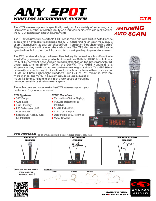
CTSThe CTS wireless system is specifically designed for a variety of performing arts. Comfortable in either a worship facility or a tour companies wireless rack system, the CTS will perform in difficult environments.The CTS features 920 selectable UHF frequencies and with built-in Auto Scan to search for an available frequencies, the CTS makes finding an open frequency a snap. Alternatively, the user can choose from 14 predetermined channels in each of 18 groups so there will be open channels to use. The CTS also features IR Sync to sync the handheld or bodypack to the receiver, making set up simple and accurate.The CTS receiver displays the transmitters battery life, as well as a Lock Function to ward off any unwanted changes to the transmitters. Both the HH85 handheld and the MBP85 bodypack have variable gain adjustment as well as three transmitter RF power adjustments (5mW, 10mW, and 20mW). The HH85 Handheld is a Magnesium alloy handheld that can endure many long tour nights. The MBP85 can come with many choices of microphone to attach to the transmitters, such as our HSM8 or ESM8 Lightweight Headsets, our LV3 or LV5 miniature lavaliere microphones, and more. The system includes a single/dual rack mount kit, for mounting one unit in one rack space or mounting two receivers side by side in one rack space.These features and more make the CTS wireless system your best choice for your next wireless.CTSR/85ESM8HSM3HSM8ESM3CTS OPTIONS-OTHER OPTIONS INCLUDE THE HH85 HANDHELD OR MBP85 BODY PACKI RS Y NCCTS System 300Range ●' Auto Scan ● True Diversity● 920 Selectable UHF ● FrequenciesSingle/Dual Rack Mount ● Kit IncludedCTSR ReceiverTransmitter Status Display ● IR Sync Transmitter to ● ReceiverAR/RF Indicators ● XLR / 1/4 Output●" Detachable BNC Antennas ● Metal Chassis●LAV SYSTEMCTSR/85LVHEADSET SYSTEMCTSR/85HSHANDHELDCTSR/HH85WIRELESS MICROPHONE SYSTEM®ANY SP TO UPGRADE YOUR SYSTEMWITH A GREAT HEADSET MICSpecifications subject to change without notice.V20190422601 E. Pawnee Wichita, KS 67211 316. 263.2852 FAX 316.263.0642 Distributed in Canada by Audio Distributors International (ADI ) 1275 Newton, unit 6 Boucherville, QC J4B 5H2 Canada450.449.8177 FAX 450.449.8180CTSSpecifications:CTS SystemAvailable Frequencies: 920Transmitter Output Level: 5 mW, 10 mW, 20 mW Band: UHF FrequencyOperating Range: Under Typical Conditions 300' (92 m), actual range depends on RF signal absorption, reflection, and inference. Audio Frequency Response: (+/-3dB) 60Hz - 16KHzTotal Harmonic Distortion: (+/-30kHz deviation, 1kHz tone): <1%Dynamic Range: >90dB A-weightedOperating Temperature Range: 14°F to 122°F (-10°C to +50°C),battery characteristics may limit this rangeIncluded Accessories: Single/Dual Rack Kit, Antenna Plugs x2,Power Supply, Antennas x2, 1/4" to 1/4" Audio Cable x1, Quick Start Guide Receiver (CTSR)Audio Output Level (+/-30kHz deviation, 1kHz tone): XLRConnector (into 600 Ohm load), 1/4" Connector (into 3k Ohm load)Output Connections: 1 Male XLR Balanced, 1/4" UnbalancedOutput Impedance: XLR connector 200 Ohms, 1/4" connector 1k Ohms XLR Output: Impedance balanced Pin 1: Ground (cable shield)Pin 2: Audio +Pin 3: No Audio -Sensitivity: -102dBm Image Rejection: >90dBCasing: Metal Chassis EIA STANDARD 1/2 UDimensions: 1.7" x 8.3" x 6.3" (45 x 212 x 160mm) (HxWxD)Weight: 31.7 oz (900 g)Power Requirements: 12Vdc at 500 mA,supplied by external power supplyDynamic Cardioid Handheld Transmitter (HH85)Max Audio Input Level: -4.44dBv (-3 gain)Gain Adjust: software control -3dB to +9dB in 3dB steps RF Output: 5 mW, 10 mW, 20 mW Frequency Response: 60Hz - 15kHzDimensions: 9.68" x 2.08" (246 x 53mm)(LxDia.)Weight: 8.8 oz (250 g) (without batteries)Power Requirements: 2 “AA” Batteries, alkaline or rechargeable Battery Life: About 12 hours (alkaline)Body Pack Transmitter (MBP85)Max Audio Input Level: -6dBV (-3 gain)Gain Adjust: -3dB, 0dB, +3dB, +6dB, +9dB RF Output: 5 mW, 10 mW, 20 mW Input Impedance: 470k OhmsDimensions: 2.51" x 3.85" x 0.90" (64 x 98 x 23 mm)(HxWxD)Weight: 3.17 oz (90 g) (without batteries)Power Requirements: 2 “AA” Batteries, alkaline or rechargeable Battery Life: About 12 hours (alkaline)WIRELESS MICROPHONE SYSTEM®ANY SP TO CTSR ReceiverBACK VIEWTOP VIEWMBP85HH85。

1/3FEATURES–Excellent live sound featuring Sennheiser's renowned evolution microphone capsules–Antenna-switching 2-channel diversity reception –Integrated antennas–Automatic frequency management and synchronization via remote channel for easy setup–Selectable UHF frequencies within a large bandwidth –Up to 10 compatible channelsDELIVERY INCLUDES–2x SKM 825-XSW or SKM 835-XSW handheld trans-mitters with mute switch and e825 cardioid dynamic capsules–2x MZQ 1 microphone clips–EM-XSW 1 DUAL stationary 2-channel receiver with internal antennas–NT 12-5 CW power supply –2x AA batteries –Quick guideXS WIRELESS 1 DUAL2-channel wireless system for singers and presenters.SPECSHEET DESCRIPTIONRaise your voice. XS Wireless 1 DUAL is a 2-channel wireless system for singers and presenters. Designed with ease of use in mind, these analog UHF systems feature a sleek dual-channel receiver with built-in antennas and the streamlined interface from Sennhei-ser's popular XS Wireless 1 series..FREQUENCY RANGES A-Range:548-572 MHzLOGISTICS INFORMATION ModelSingle itemMaster cartonXSW 1-825 DUAL weight: 2110g/1.4 lbs weight: 7360g/16.2 lbs, packs of 3XSW 1-835 DUAL weight: 2110g/1.4 lbs weight: 7360g/16.2 lbs, packs of 3EM-XSW 1 DUALweight: 1384g/3.1 lbsweight: 5182g/11.4 lbs, packs of 3TECHNICAL DATASystemModulation Wideband FMSwitching bandwidth Up to 24 MHzFrequencies 80 factory presets(8 banks of 10 channels each) Signal-to-noise ratio ≥ 103 dBATHD≤0.9%Temperature range Operation: 0°C to +40°CStorage: –20°C to +70°C Transmitter synchronization 2.4 GHz, low power OQPSK(only active during synchronization) Dimensions Ø 48 x L 180 mmWeight 330 g (0.73 lbs)Transducer principle dynamicFrequency response 55 - 16,000 HzPick-up pattern cardioidSensitivity 1.8 mV/Pa (free field, no load at 1 kHz) Nominal impedance 300 Ω (at 1 kHz)Min. terminating impedance 1 kΩConnector XLR-3Temperature range 0 °C ... +40 °C (+32 °F ... +104 °F)EM-XSW 1 DUALReceiver principle Double superheterodyneDiversity principle A Antenna switching diversity via internal antennasSensitivity (at peak deviation) < 3 μV at 52 dB(A) rms S/NAF frequency response 50 to 16,000 Hz (–3 dB)Max. AF output voltage (at peak deviation, 1 kHz AF) 1/4“(6.3 mm) socket (unbalanced):+6dBuXLR socket (balanced): +12 dBuAudio adjustment range 45 dB, adjustable in 5 dB stepsPower supply 12 V DC nom. / 300 mASquelch Adjustable from 3 dBμV to 28 dBμV Line/Mic level 20 dB, switchableHousing material Rugged ABS housingDimensions (W x H x D) approx. 320 x 126.5 x 42 mmWeight approx. 620 gSKM 825-XSW and SKM 835-XSWRF output power 10 mWAF frequency response 80-16,000 HzPower supply 2 AA size batteries, 1.5 VOperating time Approx. 10 hrsMicrophone type DynamicPick-up pattern CardioidInput sensitivity (capsule) 1.5 mV / PaTransmitter sensitivity 0 to -30 dB, adjustable in 10 dB steps Housing material Rugged ABS housingDimensions (L x Ø) Approx. 260 x 50 mmWeightApprox. 245 gcontinued on page 3VARIANTSEANUPCNo.i clei antVarArtXSW 1-825 DUAL XSW 1-825 DUAL-A 508263 4044155238242 6151043154716151043154884044155238259 XSWDUAL-B 5082641-8254044155238266615104315495DUAL-C 5082651-825XSW615104315501DUAL-D 5082664044155238273 XSW1-8254044155238280DUAL-E 5082676151043155181-825XSW4044155238297615104315525DUAL-GB 5082681-825XSW6151043155324044155238303 XSW1-825DUAL-K 508269XSW 1-825 DUAL XSW 1-835 DUAL-A 508270 4044155238310 61510431554940441552383276151043155561-835DUAL-B 508271XSW4044155238334DUAL-C 5082726151043155631-835XSW4044155238341DUAL-D 5082736151043155701-835XSW4044155238358615104315587DUAL-E 5082741-835XSW6151043155944044155238365 XSWDUAL-GB 5082751-8354044155238372615104315600DUAL-K 508276XSW1-835EM-XSW 1 DUAL EM-XSW 1 DUAL-A 508277 4044155238389 615104315617DUAL-B 50827861510431562440441552383961EM-XSW4044155238402DUAL-C 5082796151043156311EM-XSW4044155238419615104315648DUAL-D 5082801EM-XSW40441552384266151043156551DUAL-E 508281EM-XSWDUAL-GB 50828261510431566240441552384331EM-XSW40441552384406151043156791EM-XSWDUAL-K 508283。

致动V+无线中文说明书目录一、键位二、模式与模式灯三、PC电脑连接四、任天堂Switch连接五、安卓设备蓝牙连接六、关机和自动休眠七、低电量提示八、充电九、功能复位与强制断电十、按键连发十一、扳机线性开关十二、十字键与左摇杆功能互换十三、震动开关十四、摇杆精度调节十五、ABXY键位切换基础功能额外功能(以下功能非必须使用,用不到可以忽略)------------------------------------------------------------2---------------------------------------------------3----------------------------------------------------4----------------------------------------------7---------------------------------------------10-----------------------------------------------12----------------------------------------------------12-----------------------------------------------------------13------------------------------------------13------------------------------------------------------14-----------------------------------------------15-----------------------------------16----------------------------------------------------16-----------------------------------------------17----------------------------------------------18ZD-V+Wireless Controller Chinese Manual一、键位十字键右摇杆左摇杆*后续使用说明所用到的按键都以蓝色PC键位为参考。

Wi-Fi通信模块使用说明石家庄陆杰电子科技有限公司版本:20230309V1.1基本说明感谢您购买了陆杰Wi-Fi通信模块(WiFi-UART)。
本手册主要介绍Wi-Fi通信模块(WiFi-UART)使用内容。
在使用产品之前,请仔细阅读本手册,并在充分理解手册内容的前提下,进行使用软件及硬件方面的介绍,请查阅相关手册。
用户须知手册等其他技术资料中所列举的示例仅供用户理解、参考用,不保证一定动作。
将该产品与其他产品组合使用的时候,请确认是否符合有关规格、原则等。
使用该产品时,请自行确认是否符合要求以及安全,对于本产品故障而可能引发机器故障或损失时,请自行设置后备及安全功能。
责任申明手册中的内容虽然已经过仔细的核对,但差错难免,我们不能保证完全一致。
我们会经常检查手册中的内容,并在后续版本中进行更正,欢迎提出宝贵意见。
手册中所介绍的内容,如有变动,请谅解不另行通知。
联系方式如果您有任何关于本产品的使用问题,请与购买产品的代理商、办事处联系,也可以直接与陆杰公司联系。
电话:400-657-7769*************地址:石家庄栾城区邵家庄工业路2号邮编:050000网址:/未经明确的书面许可,不得复制、传翻或使用本资料及其中的内容,违者要对造成的损失承担责任。
保留包括实用模块或设计的专利许可及注册中提供的所有权力。
二零二二年六月目录一、基本说明 (4)二、硬件设备说明 (4)三、连接方式说明 (5)四、配置软件说明 (5)五、操作说明 (6)六、微信小程序使用说明 (7)七、故障排除 (10)一、基本说明Wi-Fi通信模块(Wi-Fi-UART)(以下简称模块)具备USB转232、转485、转422、串口转Wi-Fi的功能,适用PLC、HMI等串口设备的读写监控,数据传输功能。
1)通过WiFi-UART配置软件PC端或微信小程序,可以配置模块接入互联网,实现远程数据透传。
2)通过USB接口,插入电脑,可以实现USB转232(485,422)功能。
SVX Wireless SystemOnline user guide for SVX wireless system. Version: 1.0 (2022-A)Table of ContentsSVX Wireless System3安全事項3快速設定3 Shure SVX 無線系統4接收機4發射機 5系統組件6所有系統 6手持式發射機 6腰包式發射機 6電源6連接到音響系統 7頻道 7腰包增益 7 RF 水平 7靜噪 7電池電量過低指示燈 7顏色標識環 7獲得良好音質7正確放置麥克風 8佩戴頭戴式麥克風 8腰包式傳送器的佩戴 8可提高系統性能的無線使用提示9故障排除9選配附件10備件10 10頻率範圍10澳大利亞無線警告11規格 11SVXWireless System安全事項根據危險程度和損壞嚴重性的不同,使用“警告”和“小心”文字對未正確使用可能導致的後果做出標識。
警告:如果沒有遵循這些警告事項,在操作不正確的情況下可能會導致嚴重的人身傷亡事故。
小心:如果沒有遵循這些警告事項,在操作不正確的情況下可能會導致常見的人身傷害或財產損失。
警告如果有水或其他異物進入設備內部,可能會導致起火或觸電事故。
不要嘗試改裝本產品。
這樣做會導致人身傷害和/或產品故障。
小心不要拆開或改裝本設備,這樣可能會導致故障。
不要用力過大,不要拉扯線纜,否則會損壞線纜。
讓話筒保持乾燥,並避免暴露在極高溫度和濕度環境下。
快速設定Shure SVX 無線系統恭喜您購買了舒爾的 SVX 無線系統。
舒爾專業音響產品能夠提供出色的音響質量,在舞臺上經久耐用,讓您的演出輕鬆自如。
SVX 無線系統可與領夾式、手持式或頭戴式話筒一起使用,適用於演示、卡拉 OK 表演、增氧運動/健身教練或其它需要無線移動功能場合。
接收機KCX4KCX88①電源指示燈②音訊指示燈③無線電頻率密度指示燈④平衡輸出(XLR 接頭)⑤非平衡輸出(6.35 毫米接頭)⑥音訊輸出電平(線路/話筒)切換製⑦頻道選擇旋鈕⑧靜噪旋鈕⑨電源適配器輸入⑩天線發射機①電源按鈕••••••••••② 頻道選擇旋鈕③ 音訊輸入電平(線路/話筒)切換開關④ 電池艙⑤ 發射機增益旋鈕⑥ 皮帶夾⑦ 話筒輸入(CVL 領夾式或 PGA31 頭戴式)⑧ 無線電射頻 (RF) 電平切換開關⑨ 天線⑩ 顏色標識環⑪ 防滾環⑫ 電源 LED 指示燈系統組件所有系統SVX 接收機PS24 電源部件頻道選擇工具2 枚 AA 電池手持式發射機SVX2 手持式話筒發射機話筒底座轉接頭腰包式發射機SVX1 腰包式發射機話筒PG185 領夾式話筒或PG30 頭戴式話筒電源插上電源適配器,將接收機電源打開。
可编程智能中央控制系统PROGRAMMABLE CENTER CONTROL SYSTEM用户手册在使用前,请仔细阅读本用户手册目录一、可编程中控系统概述 ............................................................................................................ - 5 -1.1WIFI中控主机简介............................................................................................................... - 5 -1.1.1 系统概述........................................................................................................................... - 5 -1.1.2功能特性............................................................................................................................ - 5 -1.1.3 控制端口........................................................................................................................... - 6 -1.1.4 主要技术参数................................................................................................................... - 6 -1.1.5 规格................................................................................................................................... - 6 -1.2可编程中控主机简介........................................................................................................... - 6 -1.2.1 系统概述........................................................................................................................... - 6 -1.2.2功能特性............................................................................................................................ - 7 -1.2.3 控制端口........................................................................................................................... - 7 -1.2.4 主要技术参数................................................................................................................... - 8 -1.2.5 规格................................................................................................................................... - 8 -1.3带矩阵中控-I主机简介 (8)1.3.1 系统概述........................................................................................................................... - 8 -1.3.2 功能特性........................................................................................................................... - 8 -1.3.3 控制端口........................................................................................................................... - 9 -1.3.4 主机技术参数................................................................................................................... - 9 -1.3.5规格.................................................................................................................................... - 9 -1.4带矩阵中控-II主机简介.. (9)1.4.1系统概述............................................................................................................................ - 9 -1.4.2功能特性.......................................................................................................................... - 10 -1.4.3 控制端口......................................................................................................................... - 10 -1.4.4 主要技术参数................................................................................................................. - 10 -1.4.5 规格.................................................................................................................................. - 11 -二、系统结构体系 ...................................................................................................................... - 11 -2.1WIFI中控主机系统结构体系 (11)2.1.1 前面板说明...................................................................................................................... - 11 -2.1.2 后面板说明...................................................................................................................... - 11 -2.2可编程中控主机系统结构体系 (13)2.2.1 前面板说明..................................................................................................................... - 13 -2.2.2 后面板说明..................................................................................................................... - 13 -2.3带矩阵中控-I系统结构体系 (14)2.3.1 前面板说明..................................................................................................................... - 16 -2.3.2 后面板说明..................................................................................................................... - 16 -2.4带矩阵中控-II系统结构体系 (17)2.4.1 前面板说明..................................................................................................................... - 17 -2.4.2 后面板说明..................................................................................................................... - 18 -三、安装连接详解 ...................................................................................................................... - 19 -3.1WIFI中控主机安装连接说明 (19)3.1.1 串行控制口连接详解..................................................................................................... - 19 -3.1.2 红外发射口连接详解..................................................................................................... - 20 -3.1.3 NET口连接详解 ............................................................................................................. - 20 -3.1.4 弱电继电器口连接详解................................................................................................. - 21 -3.1.5 用户程序下载口连接详解............................................................................................. - 22 -3.1.6无线路由连接详解.......................................................................................................... - 22 -3.3可编程中控主机安装连接说明 (23)3.3.1 串行控制口连接详解..................................................................................................... - 23 -3.3.2 红外发射口连接详解..................................................................................................... - 25 -3.3.3 NET口连接详解 ............................................................................................................. - 25 -3.3.4 弱电继电器口连接详解................................................................................................. - 26 -3.3.5 用户程序下载口连接详解............................................................................................. - 27 -3.4带矩阵中控-I安装连接说明.. (28)3.4.1 串口控制口连接详解..................................................................................................... - 28 -3.4.2 红外发射/ IO口连接详解............................................................................................ - 28 -3.4.3 CRV-NET口连接详解..................................................................................................... - 29 -3.4.4 程序下载口连接详解..................................................................................................... - 30 -3.5带矩阵中控-II安装连接说明 (30)3.5.1 串行控制口连接详解..................................................................................................... - 30 -3.5.2 红外发射/IO口/可编程串口3连接详解...................................................................... - 30 -3.5.3 NET口连接详解 ............................................................................................................. - 31 -3.5.4 程序下载口连接详解..................................................................................................... - 32 -四、软件编程 .............................................................................................................................. - 32 -4.1编译、下载程序 (32)4.2红外学习 (35)4.3红外码的导入、编译、下载 (39)五、典型应用连接图 .................................................................................................................. - 42 -5.1WIFI中控主机典型应用连接图 (42)5.2可编程中控主机典型应用连接图 (43)5.3带矩阵中控-II典型应用连接图 (44)六、常见问题及解决办法 .......................................................................................................... - 44 -一、可编程中控系统概述1.1 WIFI中控主机简介1.1.1 系统概述WIFI中控主机是基于iOS平台手持终端(ipad/iphone、Android)的网络中控主机,它支持网络级联,实现智能控制网络化,并且全面兼容传统中控编程控制方式,拥有豪华亮丽的外观,她的面世,必将是新一代智能中控主机代表,引领中控领域的发展潮流。
Shure ULX WirelessULX sans fil de Shure Sistema inalámbrico ULX de Shure Sistema ULX Sem Fio da Shure©2011 Shure Incorporated27A15788 (Rev. 1)2Shure ULX WirelessULX System Components31 x UA506 1 x UA6002 x UA8201 x UA440 1 x UA507 4 x UA8201 x UA844 1 x UA507 4 x UA5061 x UA8442 x UA507Rack InstallationRackmount OptionsThe following shows rackmounting options for one to four receivers andlists the required accessories.FRONT MOUNT ANTENNA KITUA600COAXIAL CABLESUA802UA806UA825UA850UA100UA830UA870FOR LONG ANTENNA CABLE RUNSUA870UA844DISTRIBUTION AMPLIFIERANTENNA RACK MOUNT KITUA440Antenna Combiners and AccessoriesThe supplied antennas can be connected directly to the BNC-type ANTENNA connectors. However, optional antenna mounting accessories from Shure can improve reception and reduce rack clutter. Use the following guidelines:• Antennas and receivers must be from the same band.• Mount antennas more than 40 cm (16 inches) apart.• Use Shure UA825 or UA850 low-loss coaxial antenna cable (or any 50 ohm, low-loss cable such as RG-8U).Visit for more information on wireless antenna accessories.UA600Coaxial CablesInline Antenna Amplifier for long antenna cable runsAntenna Rack Mount Kit Distribution Amplifier combines antennas and power supplies formultiple receivers Active Directional Antennafor more focused receptionFront Mount Antenna Kit UA802 UA806 UA825 UA850 UA100UA830UA440UA8444Power ConnectorConnect using the supplied AC adapter or certi-fied 14–18 Vdc (550 mA) replacement supply.BatteriesPower/Mute Switch• Turn transmitter off to mute the microphone or conserve battery power.• Use the lock feature to avoid accidental muting of the microphone during a performance.Power Indicator (BAT)Green: readyRed: battery power lowNOTE: Remaining battery life varies with battery type.Both the transmitter and receiver LCD shows approximate operation time remaining for the transmitter.Battery LifeUse only 9V alkaline or lithium batteries. Typical life for common types of 9V batteries are listed below. For detailed information on battery perfor-mance, contact Shure Applications Engineering. Recommended:• Lithium (16 hours)• Alkaline (8 hours)Not recommended:• Carbon-Zinc (½ hour)• Rechargeable Ni-Cd (2 hours)• Rechargeable Ni-MH (2½ hours)NOTE:• Battery life varies with type and manufacturer.• Batteries stored for more than a year or stored in excessively hot environments may experience a higher failure rate.• Do not use rechargeable batteries with a fully-charged rating of greater than 9 V (for example, 9.6 V).• Transmitters require a minimum of 6 V to operate.12Automatic Frequency ScanChannel ScanThis feature scans for an open channel in the selected group.Group Scan (ULXP4 only)The “group scan” feature on the ULXP helps maximize the number ofsystems you can install at a single venue. It scans for wireless interfer-ence and finds the group with the most open channels.Changing Group and ChannelIf you encounter wireless interference, set the receiver and transmitter toa different channel or group.Note: You can reverse the scroll direction by holding SET andpressing MODE.Frequency Master List ModeMaster List mode offers more precise frequency selection for larger,multiple-system installations.Enter Master List mode on the receiver or transmitter by holding down theSET button for 10 seconds. Set GROUP and CHANNEL as you would innormal mode.NOTE: The unit must remain in Master List mode to operate at the se-lected frequency.Exit Master List mode by holding the SET button for 10 seconds.Single SystemIf you encounter wireless interference, perform a channel scan on the re-ceiver and use the selected channel. You usually do not need to changethe group.Multiple SystemsTo maximize performance, set all wireless systems to different channelsfrom the same group. These channels are selected to work well together.Follow these steps when using group and channel scan with multiplesystems.1. Power off all system transmitters. Turn on all other wireless or digitaldevices as they would be during the performance or presentation.2. On the first receiver: Perform a group scan. Note the selected group,then use channel scan to find the first open channel in that group.3. Power on the first transmitter and set it to the selected group andchannel.4. IMPORTANT: Leave the first transmitter powered on while setting upthe next system.5. For each additional system: Set to the same group as the first.Perform a channel scan and set the receiver and transmitter to theselected channel.6. Leave each transmitter on while setting up additional systems.Note:• Keep each transmitter at least two meters (6 feet) apart.• If using systems from different bands, set up all systems from the sameband together.Tip: To reduce setup time, you can manually set up the group and chan-nels before arriving at the venue. Visit for a list of groupsand channels that are anticipated to be free of interference in a particularcity or region.5Wireless IndicatorsRF IndicatorIndicates wireless activity over the selectedchannel.Note: When the antenna and battery indica-tors are illuminated, the RF indicator showssignal strength from the transmitter. Otherwise,it is showing interference from another source.Select a different channel.Antenna IndicatorThis indicator shows which an-tenna is receiving the strongestsignal from the transmitter.For models sold in the United States only.Displays the TV channel occupied by theselected frequency.Frequency DisplaySquelchThe factory setting offers the optimum performance for most installations.Increasing squelch filters out all but the highest quality signal, but this decreases operating range. Decreasing squelchextends the operating range, but can increase signal noise.Audio OutputAudio Output ConnectorsBalanced XLR: Connect to a mixer or other professionalaudio input. Use the MIC/LINE switch to adjust for micro-phone or line-level inputs.Unbalanced 6.35 mm (1/4”): Connect to high impedanceinputs, such as a guitar amplifier.NOTE: The LINE/MIC switch does not affect the 6.35 mm(1/4”) jack.Receiver Output LevelAdjusts the level of the receiver’s audio outputs.67Transmitter GainFor best audio quality, adjust transmitter gain so only the green and yel-low TX AUDIO LEDs flicker. (Occasional illumination of the red LED is okay.)Green=nominal Yellow=peak Red=overloadULX11. Set the attenuator (pad) switch to 0 dB for microphones and –20 dB for guitars. (Some low output instruments may not need attenuation.)2. Adjust gain control as necessary.ULX2• Fully clockwise for quiet to normal vocal performance.• Halfway counterclockwise for loud vocal performance.• Fully counterclockwise for horn or percussive instruments.Audio Input MeterPEAK IconThis icon appears when the input signaloverloads the transmitter. The icon is dis-played for 2 seconds after input overload is detected.Locking the Receiver (ULXP4 Only)This feature prevents accidental setting changes.UnlockingHold the SET button while turning the control wheel left, right, left.Locking the TransmitterLock FrequencyLock Power (On)84-PIN MINI CONNECTORTA4FTIP SLEEVEINSTRUMENT CABLECONDENSER MICROPHONE BODYPACK TRANSMITTERTroubleshootingNo power: Check battery and power supply connections and voltage. Check the power switch on the transmitter.The LCD displays “E0 00” or similar code: Exit master list mode by holding the SET button for ten seconds.Can’t turn off or change settings on the transmitter or receiver: The interface is locked. See the section on locking the interface.No audio: If the antenna and battery indicators do not appear on the re-ceiver, then it is not receiving a signal from the transmitter. Make sure the transmitter and receiver are tuned to the same group and channel.Faint or distorted audio: Adjust transmitter gain, bodypack attenuator switch, and receiver output level.Noise: Noise usually results from wireless interference or a weak signal from the transmitter. See Tips for Improving System Performance .Tips for Improving System PerformanceIf you encounter wireless interference or drop outs, try the following:• Replace the transmitter battery with a fresh alkaline battery (avoid rechargeable batteries).• Choose a different frequency channel.• Reposition the antennas so there is nothing obstructing a line of sight to the transmitter (including the audience). • Avoid placing transmitter and receiver where metal or other dense materials may be present.• Move the receiver to the top of the equipment rack (or remote mount antennas outside the rack).• Remove nearby sources of wireless interference, such as cellphones, two-way radios, computers, media players, and digital signal processors. • Keep transmitters more then two meters (6 feet) apart.• Keep the transmitter and receiver more than 5 meters (15 ft) apart.• Point the receiver antenna tips away from each other at a 45° angle, and keep them away from large metal objects. • During sound check, mark “trouble spots” and ask presenters or performers to avoid those areas.9ULXS4, ULXP4ULX2ULX1SPECIFICATIONSULX1, ULX2, ULXS4, ULXP4This Class B digital apparatus complies with Canadian ICES-003.Cet appareil numérique de la classe B est conforme à la norme NMB-003 du Canada.Meets requirements of EMC standards EN 300 422 Parts 1 and 2 and EN 301 489 Parts 1 and 9.Meets essential requirements of European R&TTE Directive 99/5/EC, eligible to bear the CE mark.ULX1, ULX2Certified under FCC Part 74. (FCC ID: DD4ULX1, DD4ULX2,DD4ULX1G3, DD4ULX2G3). Certified by IC in Canada under RSS-123 and RSS-102. (IC: 616A-ULX1, 616A-ULX2).ULXS4, ULXP4Approved under the Declaration of Conformity (DoC) provision of FCC Part 15. Certified in Canada by IC to RSS-123. (IC: 616A-ULX4). Conforms to European Regulation (EC) No. 1275/2008, as amended. Operation of this device is subject to the following two conditions: (1) this device may not cause interference, and (2) this device must accept any interference, including interference that may cause undesired operation of the device.The CE Declaration of Conformity can be obtained from Shure Incorporated or any of its European representatives. For contact informa-tion please visit The CE Declaration of Conformity can be obtained from: / europe/complianceAuthorized European representative:Shure Europe GmbHHeadquarters Europe, Middle East & AfricaDepartment: EMEA ApprovalWannenacker Str. 28D-74078 Heilbronn, GermanyPhone: +49 7131 72 14 0Fax: +49 7131 72 14 14Email:********************LICENSING INFORMATIONLicensing: A ministerial license to operate this equipment may be re-quired in certain areas. Consult your national authority for possible requirements. Changes or modifications not expressly approved by Shure Incorporated could void your authority to operate the equipment. Licensing of Shure wireless microphone equipment is the user’s respon-sibility, and licensability depends on the user’s classification and applica-tion, and on the selected frequency. Shure strongly urges the user to contact the appropriate telecommunications authority concerning proper licensing, and before choosing and ordering frequencies.Information to the userThis equipment has been tested and found to comply with the limits for a Class B digital device, pursuant to Part 15 of the FCC Rules. These limits are designed to provide reasonable protection against harmful interference in a residential installation. This equipment generates uses and can radiate radio frequency energy and, if not installed and used in accordance with the instructions, may cause harmful interference to radio communications. However, there is no guarantee that interference will not occur in a particular installation. If this equipment does cause harmful interference to radio or television reception, which can be determined by turning the equipment off and on, the user is encouraged to try to correct the interference by one or more of the following measures:• Reorient or relocate the receiving antenna.• Increase the separation between the equipment and the receiver.• Connect the equipment to an outlet on a circuit different from that to which the receiver is connected.• Consult the dealer or an experienced radio/TV technician for help. Note: EMC conformance testing is based on the use of supplied and rec-ommended cable types. The use of other cable types may degrade EMC performance.Changes or modifications not expressly approved by the manufac-turer could void the user’s authority to operate the equipment.WARNING: Dispose of properly. Check with local vendor forproper disposal of used battery and electronics.CERTIFICATION10Furnished AccessoriesMicrophone Stand Adapter (ULX2)WA371Grip/Switch Cover (ULX2)WA555Zipper Bag (ULX1)95A2313Zipper Bag (ULX2)95B2313Screwdriver (ULX2)80A498 Optional AccessoriesPassive Antenna Splitter/Combiner Kit UA221UHF Line Amplifier UA830WBUHF Powered Directional Antenna UA870WB UHF Antenna Power Distribution Amplifier (U.S.A.)UA844SWBUHF Antenna Power Distribution Amplifier (Europe) UHF Antenna Power Distribution Amplifier (UK)UA844SWB-UK33 m (100 ft.) BNC–BNC cable UA81001.8 m (6 ft.) BNC–BNC cable UA806Antenna Rack Panel UA440 Front Mount Antenna Kit (Includes 2 cables and 2 bulk-head adapters)UA600 Remote Antenna Bracket with BNC Bulkhead Adapter UA505 Front Mount Antenna Kit (Includes 2 cables and 2 bulk-head adapters)UA506Rack Mount Kit for Two Receivers UA507Carrying Case WA610Microphone Adapter Cable (XLR)WA310Replacement PartsAC Adapter (120 VAC, 60 Hz)PS41AC Adapter (220 VAC, 50 Hz)PS41ARAC Adapter (230 VAC, 50/60 Hz)PS41AZ AC Adapter (230 VAC, 50/60 Hz, Europlug)PS41EAC Adapter (230 VAC, 50/60 Hz)PS41UKAC Adapter (100 VAC, 50/60 Hz)PS41J SM58® Cartridge with Grille (ULX2/58)RPW112 BETA 58A® Cartridge with Grille (ULX2/ BETA 58)RPW118 SM86 Cartridge with Grille (ULX2/SM86)RPW114SM87A Cartridge with Grille (ULX2/87)RPW116 BETA 87A Cartridge with Grille (ULX2/BETA 87A)RPW120 BETA 87C Cartridge with Grille (ULX2/BETA 87C TM)RPW122Matte Silver Grille for SM58®RK143GMatte Silver Grille for SM86RPM226Matte Silver Grille for BETA 58A®RK265GMatte Silver Grille for BETA 87A RK312Black Grille for SM87A RK214GBlack Grille for BETA 58A RPM323G Black Grille for BETA 87A and BETA 87C RPM324GBelt Clip44A8013A1/4-Wave Antenna (470 - 752 MHz)UA400B1/4-Wave Antenna (774 - 952 MHz)UA4001/2-Wave Antenna (774 - 862 MHz)UA820A1/2-Wave Antenna (638 - 698 MHz)UA820L31/2-Wave Antenna (554 - 590 MHz)UA820D1/2-Wave Antenna (740 - 814 MHz)UA820Q1/2-Wave Antenna (470 - 530 MHz)UA820G1/2-Wave Antenna (746 - 784 MHz)UA820E1/2-Wave Antenna (572 - 596 MHz)UA820F1/2-Wave Antenna (578 - 638 MHz)UA820JAccessories and Parts11ULX FREQUENCIES FOR EUROPEAN COUNTRIESULX SYSTEM COMPATIBILITY GUIDE FOR FREQUENCY BAND X3 (925-932 MHz) ©2011 Shure Incorporated Asia, Pacific:Shure Asia Limited 22/F , 625 King’s Road North Point, Island East Hong Kong Phone: 852-2893-4290Fax: 852-2893-4055Email:**************.hk United States, Canada, Latin America, Caribbean:Shure Incorporated 5800 West Touhy Avenue Niles, IL 60714-4608 USA Phone: 847-600-2000Fax: 847-600-1212 (USA)Fax: 847-600-6446Email:**************Europe, Middle East, Africa:Shure Europe GmbH Jakob-Dieffenbacher-Str. 12,75031 Eppingen, Germany Phone: 49-7262-92490Fax: 49-7262-9249114Email:*************。
256 AVAILABLE CODES ON EACH SWITCHYou can select any one of 256 codes on Switch “A” and also any one of 256 codes on switch “B”NOTE:The manufacturer strongly recommends that you test your equipment frequently. From the time of installation, it is absolutely necessary to test the system at least once a week. It is also good practice to change the 9-volt battery every six months.NOTE:The transmitter transmits continuously with button depression. An LED lights during transmission to indicate battery operation.LIMITED WARRANTYThis product is warranted to the consumer against defects inmaterial and workmanship for one year from the date of purchase.This warranty applies to first retail buyers of new devices. Warrantorwill repair, or at its option, replace, any device it finds that requiresservice under this warranty, and will return the repaired or replaceddevice to the consumer at the warrantor’s cost. For warranty serviceand shipping instructions contact warrantor at the address shownbelow. Devices must be sent to warrantor for service at owner’sexpense. The remedies provided by this warranty are exclusive.Implied warranties under state law are to the one year period of thiswritten warranty. Some states do not allow limitations on how longan implied warranty lasts, so the above limitation may not apply toyou. In order to be protected by this warranty, save your proof ofpurchase and send copy with equipment should repair be required.This warranty gives you specific legal rights, and you may also haveother rights which vary from state to state.All products returned for warranty service require a ReturnProduct Authorization Number (RPM). Contact Linear TechnicalServices at 1-800-421-1587 for an RPA# and other importantdetails.IMPORTANTLinear radio controls provide a reliable communications link and fillan important need in portable wireless signaling. However, thereare some limitations which must be observed.*For U.S. installations only: The radios are required to complywith FCC Rules and Regulations as Part 15 devices. As such,they have limited transmitter power and therefore limitedrange.* A receiver cannot respond to more than one transmitted signalat a time and may be blocked by radio signals that occur onor near their operating frequencies, regardless of code set-tings.*Changes or modifications to the device may void FCC compli-ance.*Infrequently used radio links should be tested regularly toprotect against undetected interference or fault.* A general knowledge of radio and its vagaries should begained prior to acting as a wholesale distributor or dealer, andthese facts should be communicated to the ultimate users.Copyright © 1999 Linear Corporation207403 GDelta-3 SeriesDT-2ATwo-button DigitalTransmitterCode Setting Instructions(800) 421-1587 • Left Button "A" Right Button "B" BatteryTest LightDT-2A TWO-BUTTON TRANSMITTER CODE SETTINGThere are two digital coding switches in the DT-2A transmitter. Code Switch “A” is exposed by removing the battery access cover. It is the coding switch for the left button on the front of the transmitter (Button “A”).Code Switch “B” is the coding switch for the right button on the front of the transmitter (Button “B”). The switch is located behind the back cover of the transmitter. To access Coding Switch “B”, it is necessary to remove the screw located in the middle of the back cover.SETTING CODE SWITCH “A”Before removing the battery access door,loosen battery clip screw and rotate clip away from door. To open the battery access cover and gain access to Coding Switch “A”, lift off the small L-shaped cover by inserting your thumbnail or a small screwdriver under either of the two slots at the edge of the case. The coding switch has eight keys numbered 1-8.To set a code, select any combination of ON or OFF positions for the switch keys numbered 1-8. Use a paper clip or other pointed object (except a pencil or pen) to set the keys on the coding switch. The ON position is when the top of the switch is down.SETTING CODE SWITCH “B”To gain access to Coding Switch “B”, first remove the screw in the middle of the back cover. Remove the back cover to expose the 8-key switch.To set a code, select any combination of ON and OFF positions for the switch keys, in the same manner as described for Coding Switch “A”.CAUTION:It is not advisable to set a code with all keys ON, OFF, or alternating ON and OFF,because these codes are too easy to duplicate.TRANSMITTERS CODE MUST MATCH RECEIVER CODESwitch “A” is designed for use with a garage door opener. The code set to Switch “A” must be identical to the code set in the receiver to be used in conjunction with Push-button “A”Switch “B”, under the back cover is designed for use with less-frequently changed codes,such as a community gate operated by Push-button “B”. The code set into Switch “B”must be identical to the code set in the receiver to be used in conjunction with Push-button “B”.BATTERYCODING SWITCH "A"ROTATE CLIP AWAY FROM BATTERY DOOR587143O FFON6Keys 1, 2, 3, 4, and 6 OFFKeys 5, 7 and 8 ONCODING SWITCH "A"CODING SWITCH "B"REAR VIEW WITHBACK COVER REMOVED TO ACCESS SWITCH "B"。
VIA Collage操作手册快速使用向导:
一、VIA设备本身的设置:
1.检查包装盒内设备及配件:
a)
b)
c)
d) VIA Collage设备一台
电源适配器一个(19V)及电源线3根
DP转H D MI适配器一个
快速使用向导说明一份
2.设备接口概览:
VIA Collage
3)
4) 连接设备
a)
b)
c)
d)
连接U SB鼠标、键
盘
通过H DMI线缆连接主显示设备,选项:通过D P转HDMI连接第二个显示设备
通过网线连接至W IFI路由器
连接电源,开启设备
配置设备:首次使用设备,可通过设备客户端中的”设置”选项来进行配置,
用户名:su 密码:supass
设置菜单中的选项:
a) 网络设置:配置V IA Collage的I P地址,使其处于路由器同一网段内,更改设置
后
需要重启V IA;默认的I P地址:192.168.1.39
b) 房间名称/密码:将房间名称更改为设备的I P地址,更改设置后需要重启
VIA
默认的房间名称:192.168.1.39
二、用户客户端设置: 1. 2.
通过 W IFI 或者有线连接终端设备(电脑, iPad,手机)到同一网络 下载安装客户端:
MAC 或者 PC : a) b) 通过 I E 浏览器,访问 V I A
的 I P 地址 选择 ”C lick to Run ”下载免安装版客户端
(一次用户使用)
选择 ”C lick to Install ”下载安装版客户端
(常用用户使用)
iOS / Android 系统的手机或 P ad:
在 A pp Store 或者
G o ogle Play 搜索 Kramer VIA ,下载免费应用 运行、登陆客户端: a) 3.
房间名称:输入 V IA 的
IP 地址
用户名:设备的昵称 密码:4位数字的密码,显示在屏幕左下
角
输入完成后,点击登陆,客户端登陆后, 进入主菜单
4. 主菜单:
a) 点击 “进入”可将终端设备的屏幕投放到主屏幕上;选择 “退出”屏幕,退
出主屏 幕显示,单个屏幕可以显示 6个画面,两个屏幕可以同时显示 12个画面;主屏幕
的显示模式,可通过主机功能菜单下的 “Display Layout ”进行更改
点击 “参与者”可查看所有加入的 V I A 平台的用户 b) c) 点击 “特性”进入子菜单,可使用菜单下的各项功
能
5. 特性菜单下功能介绍:
a) 多媒体:
i. 选择 “多媒体”选项后,可将视频文件直接拖拽到该功能下进行添加文件
也可以通过 “添加媒体文件”,将视频文件添加到该功能下 选中需要播放的文件,点击工具条上面的播放按钮,可播放文件 支持的文件格式:avi, vob, mp4, mov, mpx, mpk 等,1080P@60Hz
选中想要删除的文件,选择 ”删除媒体文件”,可将文件从列表中删除 ii.
iii.。