JR胶管扣压参数表
- 格式:xls
- 大小:13.86 KB
- 文档页数:1
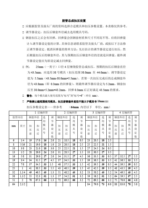
胶管总成扣压设置
◆应根据胶管及接头厂商的资料选择合适模具和扣压参数设置,本表格仅供参考。
◆调节器设定:扣压后钢套外径减去选用模具号码。
◆钢套扣压之后会有回弹,回弹量会因钢套材质和尺寸不同而不等。
应将回弹量
计入调节器设定值的计算。
具体信息请联系胶管及接头厂商,或按以下方法修正调节器设定。
抵消回弹量的简单方法:先以估计的调节器设定进行扣压,然后测量扣压后的钢套外径,其与预期扣压后钢套外径的差就是回弹量。
最终调节器设定值应为原设定减去回弹量。
◆例:25mm(一英寸)口径4层缠绕胶管总成扣压,预期的扣压后钢套直径
为43.5mm,应选用38号模具(扣压范围38.0mm 至44.0mm)。
调节器设定值为 5.5mm(43.5mm-38.0mm=5.5mm)。
若第一次扣压完成后的总成钢套外径为43.8mm(即0.3mm的回弹量),则最终调节器应设定为5.2mm。
钢套扣压至38.0mm+5.2mm=43.2mm,回弹0.3mm后正好满足43.5mm的要求。
◆ 警告:每个模具最大使用范围为“标号”到“标号+6”(单位mm)。
◆ 严格禁止超范围使用模具。
扣压前钢套外直径不能大于模具号10mm!!!
扣压参数设定表——供参考(64mm内径以下单位:mm)。

![高压胶管接头的扣压参数[精彩]](https://img.taocdn.com/s1/m/a24f3db8dc3383c4bb4cf7ec4afe04a1b071b015.png)
高压胶管接头的扣压参数高压胶管扣压时,把胶层和钢丝嵌入接头的外套内壁及芯子外圆柱面部切有的环形槽内,松紧要适宜。
过紧会使接头芯子内孔产生变形,并将胶管扣压伤,过松,当胶管承压之后接头会被拔脱高压胶管与接头扣时,一定要掌握高压胶管的压缩率:二要掌握接头外套的扣压量,并根据高压胶管内径和高压胶管钢丝层外径的变化以及高压胶管压缩率进行计算,以确保接头和胶管扣压牢固,接头外套扣压后的直径计算公式为D:D=(d1-d2)+【D0-(D2-D1)】-E(D1-d2-A)( m m )式中-接头和胶管扣压后的直径;D0一外套外径;D2-外套内径D1 一钢丝层外径d1一接头芯子外径}d2一胶管内径’A一钢丝层厚度’E 一压缩率。
E值:1层0.4-0.43,2层0.43-0.46,3层0.46-0.50。
4层0.55-0.60高压胶管的制作流程用混炼机按配方混炼出内层胶、中层胶和外层胶;用挤出机挤出内层胶管,包覆在涂了脱模剂的软芯或硬芯上(液氮冷冻法也可不用管芯);压延机压成中层胶薄片,加隔离剂收卷并按工艺要求裁成规定宽度;将含管芯内层胶管在缠绕机或编织机上缠绕上镀铜钢丝或镀铜钢丝绳,同时在缠绕机或编织机将中层胶薄片同步缠绕在每两层镀铜钢丝或镀铜钢丝绳间,缠绕钢丝起头和结尾处绑扎(有些早期缠绕机需预先将镀铜钢丝进行预应力定型处理);再次在挤出机上包覆上外层胶,然后再包缠铅或布硫化保护层;通过硫化罐或盐浴硫化;最后拆去硫化保护层,抽出管芯,扣压上管接头,抽样打压检验。
总之,制造高压胶管使用设备多、原料种类多,生产工艺复杂。
但近年来以塑料或热塑性弹性体为主要原料的液压油管生产工艺可适当简化,但原料价高,仍以橡胶原料为主。
纤维编织缠绕胶管生产中常见质量问题及改进措施(经验之谈)(续夹布胶管生产中常见质量问题及改进措施)纤维编织缠绕胶管的生产工艺亦分硬芯法、软芯法、无芯法三种。
其中硬芯法、软芯法生产技术疑难问题不多,某些质量问题与夹布胶管相似,其解决办法与采取措施也可参照夹布胶管。
管接头工作压力一览表ISO8434-1/ISO6149-2-31CH/1DHISO8434-1/ISO9974-2-3/ISO1179-2-41CM-WD/1DM-WD/1CG/1DG/1CB-WD/1DB-WD焊接接头2WD/2WDISO6149-2(S SERIES)ISO 6149-3 (L SERIES)1H/1H-OG(重系列) 1H/1H-OG(轻系列)ISO 11926-2/ISO 11926-31O/1O-OG(轻重系列)ISO 6162-1/ISO 6162-2FL/FSISO 8434-21JISO 8434-31FISO 9974-2/ISO 9974-31M-WD/1M-CSBS 52001BISO/TC 131/SC 4 N 430 – ISO/CD 8434-1 – 2003-04-036© ISO 2003 – All rights reserved5.3 According to different applications and different pressure ratings, there are three series of connectors. Theseries are referred to as:–– LL: extra light-duty;–– L: light-duty;–– S: heavy-duty.Ranges of the tube outside diameters and pressure requirements are shown in Tables 1 to 3.Table 1 — Working pressures for 24o cone connectors for fluid power and general use Series Tube outsidediameter(Tube OD)Cone end ISO 6149-2 or -3 stud ends ThreadMaximum working pressure a Thread Maximum working pressure a mmMPa (bar b ) MPa (bar) 4 M8 x 1 10 (100) ––– ––– ––– 5 M10x 1 10 (100) ––– –––––– 6 M10x 1 10 (100) ––– ––––––LL 8M12 x 1 10 (100) ––– ––– –––6 M12 x 1,5 25 (250) M10 x 1 25 (250)8 M14 x 1,5 25 (250) M12 x 1,5 25 (250)10 M16 x 1,5 25 (250) M14 x 1,5 25 (250)12 M18 x 1,5 25 (250) M16 x 1,5 25 (250) L15 M22 x 1,5 25 (250) M18 x 1,5 25 (250)18 M26 x 1,5 16 (160) M22 x 1,5 16 (160)22 M30 x 2 16 (160) M27 x 2 16 (160)28 M36 x 2 10 (100) M33 x 2 10 (100)35 M45 x 2 10 (100) M42 x 2 10 (100)42 M52 x 2 10 (100) M48 x 2 10 (100)6 M14 x 1,5 63 (630) M12 x 1,5 63 (630)8 M16 x 1,5 63 (630) M14 x 1,5 63 (630)10 M18 x 1,5 63 (630) M16 x 1,5 63 (630) S12 M20 x 1,5 63 (630) M18 x 1,5 63 (630)16 M24 x 1,5 40 (400) M22 x 1,5 40 (400)20 M30 x 2 40 (400) M27 x 2 40 (400)25 M36 x 2 40 (400) M22 x 2 40 (400)30 M42 x 2 25 (250) M42 x 2 25 (250)38 M52 x 2 25 (250) M48 x 2 25 (250) NOTE For higher pressure ratings and for dynamic conditions, the manufacturer shall be consulted.a With a design factor of 4 to 1.b 1 bar = 105 N/m 2 = 10 5 Pa = 0,1 MPa.ISO/TC 131/SC 4 N 430 – ISO/CD 8434-1 – 2003-04-03© ISO 2003 – All rights reserved 7Table 2 — Working pressures for 24o cone connectors, for general use only Series Tube OD Cone endISO 9974 stud ends ISO 1179 stud endsThread Maximum working pressure aThread Maximum working pressure aThread Maximum working pressure aISO 9974-2 (type E)b ISO 9974-3 (type B)c ISO 1179-2 (type E)b ISO 1179-4(type B)cmm MPa (bar) MPa (bar) MPa (bar) MPa (bar) MPa (bar) 4 M8 x 1 10 (100) M8 x 1 ––– ––– 10 (100) G 1/8 A ––– ––– 10 (100) LL 5 M10 x 1 10 (100) M8 x 1 ––– ––– 10 (100) ––– ––– ––– ––– ––– 6 M10 x 1 10 (100) M10 x 1 ––– ––– 10 (100) ––– ––– ––– ––– ––– 8 M12 x 1 10 (100) M10 x 1 ––– ––– 10 (100) ––– ––– ––– ––– ––– 6 M12 x 1,5 25 (250) M10 x 1 25 (250) 25 (250) G 1/8 A 25 (250) 25 (250)8 M14 x 1,5 25 (250) M12 x 1,5 25 (250) 25 (250) G 1/4 A 25 (250) 25 (250) 10 M16 x 1,5 25 (250) M14 x 1,5 25 (250) 25 (250) G 1/4 A 25 (250) 25 (250) 12 M18 x 1,5 25 (250) M16 x 1,5 25 (250) 25 (250) G 3/8 A 25 (250) 25 (250) L 15 M22 x 1,5 25 (250) M18 x 1,5 25 (250) 25 (250) G 1/2 A 25 (250) 25 (250) 18 M26 x 1,5 16 (160) M22 x 1,5 16 (160) 16 (160) G 1/2 A 16 (160) 16 (160) 22 M30 x 2 16 (160) M26 x 1,5 16 (160) 16 (160) G 3/4 A 16 (160) 16 (160) 28 M36 x 2 10 (100) M33 x 2 10 (100) 10 (100) G 1 A 10 (100) 10 (100) 35 M45 x 2 10 (100) M42 x 2 10 (100) 10 (100) G 1 1/4 A 10 (100) 10 (100) 42 M52 x 2 10 (100) M48 x 2 10 (100) 10 (100) G 1 1/2A 10 (100) 10 (100) NOTE For higher pressure ratings and for dynamic conditions, the manufacturer shall be consulted.a With a design factor of 4 to 1.b Type E with elastomeric sealing.c Type B with metal-to-metal sealing.ISO/TC 131/SC 4 N 430 – ISO/CD 8434-1 – 2003-04-038© ISO 2003 – All rights reservedTable 2 — Working pressures for 24o cone connectors, for general use only (concluded) Series Tube OD Cone end ISO 9974 stud end ISO 1179 stud end Thread Maximum working pressure a Thread Maximum working pressure a Thread Maximum working pressure a ISO 9974-2 (type E)b ISO 9974-3 (type B)c ISO 1179-2 (type E)b ISO 1179-4 (type B)c mm MPa (bar) MPa (bar) MPa (bar) MPa (bar) MPa (bar) 6 M14 x 1,5 63 (630) M12 x 1,5 63 (630) 40 (400) G 1/4 A 63 (630) 40 (400) 8 M16 x 1,5 63 (630) M14 x 1,5 63 (630) 40 (400) G 1/4 A 63 (630) 40 (400) 10 M18 x 1,5 63 (630) M16 x 1,5 63 (630) 40 (400) G 3/8 A 63 (630) 40 (400) 12 M20 x 1,5 63 (630) M18 x 1,5 63 (630) 40 (400) G 3/8 A 63 (630) 40 (400) S 16 M24 x 1,5 40 (400) M22 x 1,5 40 (400) 40 (400) G 1/2 A 40 (400) 40 (400) 20 M30 x 2 40 (400) M27x 2 40 (400) 40 (400) G 3/4 A 40 (400) 40 (400) 25 M36 x 2 40 (400) M33 x 2 40 (400) 25 (250) G 1 A 40 (400) 25 (250) 30 M42 x 2 25 (250) M42 x 2 25 (250) 16 (160) G 1 1/4 A 25 (250) 16 (160) 38 M52 x 2 25 (250) M48 x 2 25 (250) 16 (160) G 1 1/2 A 25 (250) 16 (160) NOTE For higher pressure ratings and for dynamic conditions, the manufacturer shall be consulted. a With a design factor of 4 to 1. b Type E with elastomeric sealing. c Type B with metal-to-metal sealing.ISO/TC 131/SC 4 N 430 – ISO/CD 8434-1© ISO 2003 – All rights reserved 9Table 3 — Working pressures for 24° cone weld-on nipples with various tube wall thicknesses Dimensions in millimetresMaximum working pressure 10 MPa (100 bar)16 MPa (160 bar) 25 MPa (250 bar) 31,5 MPa (315 bar) 40 MPa (400 bar) 63 MPa (630 bar)Series TubeOD Tube ID aT b Tube ID a T b Tube ID a T b Tube ID a T b Tube ID a T b Tube ID a T b 6 3 1,5 3 1,5 3 1,5 8 5 1,5 5 1,5 5 1,5 10 7 1,5 7 1,5 7 1,5 12 8 2 8 2 8 2 15 10 2,5 10 2,5 10 2,5 18 13 2,5 13 2,5 22 17 2,5 17 2,528 23 2,5 35 29 3L 42 36 36 2,5 1,75 2,5 1,75 2,5 1,75 2,5 1,75 2,5 1,75 2,5 1,75 8 4 2 4 2 4 2 4 2 4 2 4 2 10 6 2 6 2 6 2 6 2 6 2 5 2,5 12 8 2 8 2 8 2 8 27 2,5 6 3 16 11 2,5 11 2,5 11 2,5 11 2,5 10 3 20 14 3 14 3 14 3 14 3 12 425 19 3 19 3 19 3 17 4 16 4,530 24 3 24 3 22 4S 38 32 3 32 3 28 5NOTE For pressure and/or temperature applications outside those given in this part of ISO 8434, the manufacturer shall be consulted.aID = inside diameter. b T = tube wall thickness.6 Designation of connectors6.1 Connectors shall be designated by an alphanumeric code to facilitate ordering. They shall be designated by the word “Connector” followed by ISO 8434-1, followed by a hyphen, then the connector style letter symbols (see6.2), followed by a spaced hyphen, then the series letter (see 5.3) immediately followed by the outside diameter of the tube with which they are to be connected. For weld nipples, a multiplication sign (x) follows, then the tube wall thickness. There shall be no spaces on either side of the multiplication symbol. For stud ends (connector ends), another spaced hyphen followed by the thread designation of the stud end and the sealing type shall be added.6.2 The letter symbol designation of the connector style shall have three parts: the connection end type immediately followed by the shape of the connector, and by the indication that a complete connector is ordered.6.3 Tube ends are assumed and thus do not need to be included in the code. However, if another type of end is involved, it shall be designated.6.4 Reducing connectors and reducing elbows shall be designated by specifying the larger tube end first.。