三偏心蝶阀说明书
- 格式:doc
- 大小:574.50 KB
- 文档页数:8
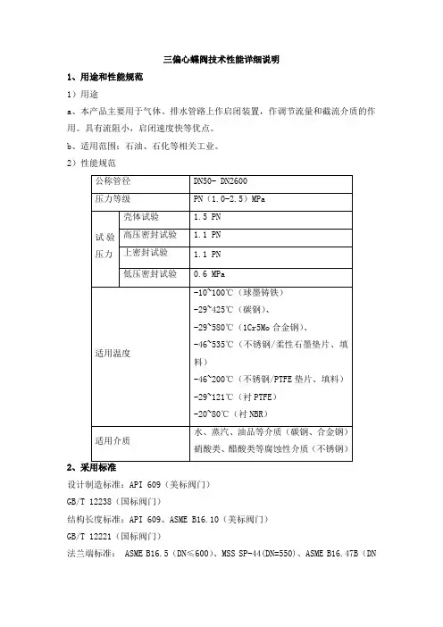
三偏心蝶阀技术性能详细说明1、用途和性能规范1)用途a、本产品主要用于气体、排水管路上作启闭装置,作调节流量和截流介质的作用。
具有流阻小,启闭速度快等优点。
b、适用范围:石油、石化等相关工业。
2)性能规范2设计制造标准:API 609(美标阀门)GB/T 12238(国标阀门)结构长度标准:API 609、ASME B16.10(美标阀门)GB/T 12221(国标阀门)法兰端标准: ASME B16.5(DN≤600)、MSS SP-44(DN=550)、ASME B16.47B(DN≥650)(美标阀门)HG/T20592 系列A、 GB/T 9113或HG/T 20592或JB 79等(国标阀门)检验试验标准:API 598(美标阀门)GB/T 26480(国标阀门)3、三偏心蝶阀外型结构图三偏心蝶阀结构图4、结构特点1、硬密封蝶阀采用三偏心硬密封结构,阀座与蝶板几乎无磨损,具有越关越紧的密封功能。
2、密封圈选用不锈钢制作,具有金属硬密封和弹性密封的双重优点,无论在低温和高温的情况下,均具有优良的密封性能,具有耐腐蚀,使用寿命长等特点。
3、蝶板密封面采用堆焊钴基硬质合金,密封面耐磨损,使用寿命长。
4、大规格蝶板采用绗架结构,强度高,过流面积大,流阻小。
5、根据用户需求,硬密封蝶阀可以设计成具有双向密封功能,安装时不受介质流向的限制,也不受空间位置的影响,可在任何方向安装。
6、驱动装置可以多工位(旋转90°或180°)安装,便于用户使用。
5、装运和储存1、运输前的准备阀门端部通道和阀门外露表面是关键的部位,应采取下列措施:(a)阀门内部应清除滞留水垢,保持阀门内腔清洁、干燥。
(b)阀门外露机加工面应涂防锈油。
(c)阀门端部应有防止法兰面等机械损伤的措施。
(d)阀门启闭件应处于关闭状态。
2、搬运搬运阀门时应适当加以注意,阀门决不能抛扔或跌落,特别是手轮和阀杆不应作大型阀门的起吊或悬挂点。
Krombach® Large Bore ValvesCrane ChemPharma & Energy2Crane ChemPharma & EnergyBacked by Crane’s 160-year tradition of engineering excellence, Krombach® brand butterfly valves from Crane ChemPharma & Energy deliver superior solutions to a range of industrial applications. Available in both Double Offset (DOV) and Triple Offset (TOV) designs, Krombach’s vast experience in the power and water markets ensures exceptional quality and reliable solutions in the industry’s most demanding applications.Applications that require "bubble-tight" shutoff demand the superior sealing capabilities of Triple Offset butterfly valves. While traditionalbutterfly valves can likewise suffer in volatile chemical applications and are prone to clogs in particulate media, Triple Offset valve technology delivers superior performance and protection in the industry’s most demanding environments.What is a DOV?To allow for easy seat displacement, the valve is designed with a double offset (DOV= double offset valves). The shaft is offset from the centerline of the bore (first offset), and the centerline of the disc seat and body seal (second offset). Together, the offsets create an eccentric disc movement that lifts the seat out of the seal,resulting in friction during the first 10 degrees of opening and final 10 degrees of closing.Figure 3: Double-offset butterfly valve designFigure 7: Details of the geometric sealing design. Both compo-nents are machined into an offset conical profile, resulting in a right-angle cone.Figure 6: Third off-set “right-angled cone” seat designWhat is a TOV?The valve is designed with a triple offset (TOV= triple offset valves), where the third offset is the geometric design of the disc and the seat. Both components are machined into an offset conical profile, resulting in a right-angle cone. This ensures nearly friction-free operation of the 90° movement. The contact is made in only the final point of closure, acting as a mechanical travel stop. This prohibits over-travel of the disc.3Figure 4: First offset of the shaft to the centerline of the boreFigure 5: Second offset from the centerline of the disc seat and body seal12Figure 1: First offset of the shaft to the centerline of the boreFigure 2: Second offset from the centerline of the disc seat and body seal123Crane ChemPharma & EnergyKrombach DOV Krombach TOVG MCooling Water Boiler Feed Water PumpLP Turbine TurbineSteam: High/Intermediate pressure up to 400 psig @ max 1100°F Water: Low/Intermediate pressure up to 2000 psig @ maxApplicationsHEAT RECOVERY STEAM GENERATORCOMBINED CYCLEKrombach DOV Krombach TOV4Crane ChemPharma & EnergySingle- or b idirectional locking device secures disc position whilemaintenance is performed, facilitating in-line repair and enhancing safety.Design FeaturesTop mounting flange in accordance with ISO 5211is suitable for manual gear, electric,hydraulic and pneumatic actuation.Welded design increases versatility to meet several design standards in face to face dimensions, pressure ratings and pipe connection.• DIN• ANSI/ASME • AWWA5Crane ChemPharma & EnergyDifferent materials for sealing element available inEPDM-10°C to 200°C / 14°F to 390°F NBR-15°C to 100°C / 5°F to 212°F FKM-10°C to 200°C / 14°F to 390°FDesign FeaturesSafety lock for locking device optional available prevents accidental open-ingThe sealing element is carried by disc and the seat retainer ring is replaceable. This ensures easier maintenance and facilitates the adjust ability of the sealingelement.(The application might changethe temperature range)6Crane ChemPharma & EnergyFeatures and BenefitsMaterials❶Key FeaturesRub b er-lined sealing element Rubber-lined sealing on the disc facilitates maintenance, reduces friction between seat and seal in the first 10 degrees on opening and last 10 degrees of closing. This extends the service life.Available in single or bidirectionalconfigurations, the locking device secures disc position while maintenance is performed on the disc, facilitating in-line repair and enhancing safety.Rubber lined options deliver superiorperformance and protect sensitive valve components in corrosive applications.* other materials upon requestDisc in open positionDisc in half-open position Disc in closed positionDisc Operation7Crane ChemPharma & EnergySizesConnections• Flanged design according to DIN EN 1092-1, ASME B 16.47-RF, and AWWA C207• Buttwelded Ends*Face to Face Dimensions• Face to face dimensions according to DIN EN 558-1 R14, ASME 16.10, and AWWA C504Temperature• Liner EPDM-20°C to 120°C / -4°F to 250°F*• Liner NBR-15°C to 100°C / 5°F to 212°F*• Liner FKM-10°C to 200°C / 14°F to 390°F*Certifications• Design according to UVV-O 2Applications• Cooling water cycle isolation (Power industry) • Drinking water pump stations • Desalination plantsOptions• Electric heat tracing/jacket to prevent freezing in low-temperature applications• Stem extension with stuffing box possible upon request• Hard-rubber lined version available for seawater applications (specification of rubber lining depending on application)* other sizes available on requestTechnical Specifications* either Krombach design or customer requirements* the application might reduce the applicable temperature range8Crane ChemPharma & Energy Design FeaturesNo contact between sealing elements during 90° operation reduces wear and maintenance over a long life time.Torque-generated sealingUnlike position-seated ball valves, resilient seated butterfly valves and plug valves, the Krombach TOV is seated with the application of torque. The right-angle conical design enables sealing by contact, rather than through the friction generated by the elastic deformation of the seat.ISO 5211actuation.9Crane ChemPharma & EnergyDesign FeaturesWelded design offers the versatility to meet several design standards regarding face-to-face dimensions, pressure rating and pipe connection.• DIN• ANSI/ASME • AWWAThe sealing element is carried by disc and the seat retainer ring is replaceable. This ensures easier maintenance and facilitates t he a djustability of the sealing element.10Crane ChemPharma & EnergyFeatures and BenefitsMaterials❶Key FeaturesA wider seat angle (24°) and self-releasingmechanism prevent excessive rubbing, sticking or galling of the laminated portion of the disc, enabling longer service life and lower operating torque with smaller actuators.Metallic seat offers superior leakprotection in volatile high-pressure and temperature applications and aremanufactured in accordance with ISO5208 and EN 12266-2.Self-centering disc design ensureshigh-integrity in-line sealing even whenthe seal is offset, and delivers exceptional performance in high- temperature cycling.* other materials upon request11Crane ChemPharma & EnergySizesConnections• Flanged design according to DIN EN 1092-1, ASME B 16.47-RF, and AWWA C207• Buttwelded Ends*Face to Face Dimensions• Face to face dimensions according to DIN EN 558-1, ASME 16.10, and AWWA C504Temperature• -20°C to 550°C / -4°F to 1100°F*Certifications• Design according to UVV-O 2Applications• Compressor blow-off (quick opening) • Steam / combustion turbines• Steam / combustion lines on an air condenserOptions• Electric heat tracing/jacket to prevent freezing in low-temperature applications• Stem extension with stuffing box possible upon request• Single or bidirectional locking device available* other sizes available on requestTechnical Specifications* the application might reduce the applicable temperature range* either Krombach design or customer requirementsC P E -K R O M B A C H -L A R G E B O R E -B U -E N -A 4-2014_09_08Friedrich Krombach GmbH ArmaturenwerkeMarburger Str. 364 57223 Kreuztal, Germany Tel: +49 2732 520 00Fax: +49 2732 520 100Crane ChemPharma & EnergyCrane Co. and its subsidiaries cannot accept responsibility for possible errors in catalogues, brochures, other printed materials, and website information. Crane Co. reserves the right to alter its products without notice, including products already on order provided that such alteration can be made without changes being necessary in specifications already agreed. All trademarks in this material are property of the Crane Co. or its subsidiaries. The Crane and Crane brands logotype, in alphabetical order, (ALOYCO®, CENTER LINE®, COMPAC-NOZ®, CRANE®, DEPA®, DUO-CHEK®, ELRO®, FLOWSEAL®, JENKINS®, KROMBACH®, NOZ-CHEK®, PACIFIC VALVES®, RESISTOFLEX®, REVO®, SAUNDERS®, STOCKHAM®, TRIANGLE®, UNI-CHEK®, WTA®, and XOMOX®) are registered trademarks of Crane Co. All rights reserved.© Crane ChemPharma & Energybrands you trust.。

三偏心蝶阀说明书一、特点及用途:该阀门采用三偏心金属密封结构,在室温或高温下均具有良好的密封性能,与同规格闸阀或截止阀相比,体积小,重量轻,启闭灵活,使用寿命长,广泛适用于冶金、轻工、电力、石油化工、煤气水道等领域,使用安全可靠,该阀门是现代化企业最理想的选择。
二、标准规范:D343H-16C/25 D373H-16C/25按照下列标准执行1.设计制造与检验按照JB/T8527-1997规定。
2.法兰连接尺寸按GB9113.3-88;GB9113.4-88的规定。
3.结构长度按GB12221-89的规定。
4.阀门压力试验按GB/T13927-92的规定。
D343H-150Lb D373H-150Lb 按照下列标准执行1.设计制造与检验按照API 609规定。
2.法兰连接尺寸按API 609的规定。
3.结构长度按API 609的规定。
4.阀门压力试验按API 598的规定。
三、主要性能规范:公称压力PN GB1048ANSI 150LBMPa1.0 1.62.5 2.2 强度密封试验压力PS 1.5 2.43.8 3.0 高压密封试验压力PS 1.11.762.82.2低压气密封试验压力PS0.6材质 WCB 适用温度℃ -29~425 适用介质水、蒸气、油品四、主要零件材料 零件名称 阀体、蝶板、支架压板 阀杆 密封圈 D343H-16C/25 D373H-16C/25WCB252Cr131Cr18Ni9/XB450D343H-150LbWCB 25 2Cr13 1Cr18Ni9/XB450 D373H-150Lb五、三偏心金属密封蝶阀的密封原理:图1为本公司生产的典型三偏心金属密封蝶阀密封副结构简图。
(1)结构特征。
蝶板回转中心(即阀门轴中心)与蝶板密封面形成一个尺寸A偏置,并与阀体中心线形成一个B偏置;阀体密封面中心线与阀座中心线(即阀体中心线)形成一个角度为β的角位置。
(2)密封原理。
气动硬密封三偏心蝶阀使用说明书1.产品概述气动蝶阀具有优良的切断性能和调节性能,其阀板与密封组件采用了金属U型弹性阀座和三偏心阀板结构。
阀板形状为椭圆形圆锥体。
当阀门打开时,椭圆形圆锥体密封面先脱离U形弹性阀座,然后再旋转,这样可降低摩擦阻力和磨损。
当阀门关闭时阀板旋转,在偏心轴的作用下阀板向弹性阀座进行自动调整中心,对阀座压紧,使阀座变形,直到阀座与阀板椭圆形圆锥密封面紧密吻合,从而保证密封要求,减少了阀门开启所需的扭矩,延长了阀门的使用寿命。
该两大系列产品具有调节及快速切断、调节等三种功能,是经济实用型自动控制阀,特别适用于石化、电力、冶金、轻工等工业部门使用。
2.主要技术参数2.1 阀体型式:扁平偏置铸造或锻造阀体公称通经:DN50—800mm公称压力:PN1.6、2.5、4.0MPa连接型式:无法兰对夹式RF型或法兰连接RF型材料:WCB CF8 CF8M填料:石棉浸四氟聚四氟乙烯柔性石墨2.2 阀内组件阀芯型式:偏心旋转式阀板材质:WCB镀硬铬、CF8、CF8M阀座材料:软密封(R型):聚四氟乙烯温度范围:-40—+180℃对位聚苯温度范围:-40—+300℃硬密封(Y型):304或316,温度范围:-40—+425℃阀轴材料:17-4PH 3163.主要技术性能指标表18.主要外形尺寸4.产品结构及工作原理气动蝶阀主要由气动活塞执行机构及蝶阀阀体部件两大 部分组成。
也可配装手操机构或相关附件等组成。
4.1气动活塞执行机构 4.1.1产品结构气动活塞执行机构主要由气缸缸体、活塞、端盖、齿轮轴、 密封圈及弹簧等组成。
分双作用(H)型和单作用(T)型两种。
4.1.2工作原理(一)双作用型工作原理(标准转向)俯视(二)单作用型(弹簧复位)工作原理(标准转向)俯视标准旋转方向是:顺时针关,逆时针开※对于关闭压差较大,需要配装拨叉式较大输出力气缸执行机构时,可配装6500RA 型气动活塞执行机构。
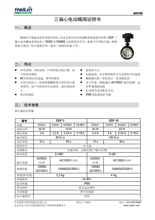
三偏心电动蝶阀说明书一、概述蝶阀用于暖通及制冷系统中热水、冷冻水和冷却水的通断和流量调节控制。
DDF三偏心电动蝶阀系列包括了DN50至DN800之间的所有型号,配备开关型执行器。
阀体和执行器出厂时已装配完毕,减少了现场的安装工序。
二、特点⚫外形美观、结构紧凑, 小型轻便,安装方便,易于拆装及维修⚫90度回转启闭迅速,调节性能好⚫启闭力矩较小,转轴两侧蝶板受介质作用力基本相等,而产生转矩的方向相反,故启闭较省力⚫密封性能好⚫流体阻力小⚫功能强劲,有多种控制信号与反馈信号供选择⚫蜗轮输出轴一体化设计,传动精度高⚫安全可靠,能够通过AC1500V耐压检测,选用F级绝缘电机⚫启动和关闭次数2万次⚫IP65高标准防护等级三、技术参数执行器技术参数阀体技术参数注:蝶板材料一般为铸钢,如果需要其它材质,订货时请注明。
四、 尺寸及阀体执行器配置表对夹连接:DN50-DN450 DN500-DN800单位:mm法兰连接:DN50-DN450 DN500-DN800北京海林节能科技股份有限公司第6页 共12页 电话:************Kv 值表 公称 通径 蝶板位置(开启90°为全开) 10° 20° 30° 40° 50° 60° 70° 80° 90° DN50 0.1 4.3 10.3 20.6 38.6 54.8 77.1 107.1 115.7 DN65 0.2 6.9 17.1 31.7 55.7 84.0 123.4 174.8 188.5 DN80 0.3 10.3 18.9 33.4 60.0 99.4 156.8 235.6 258.8 DN100 0.4 14.6 30.8 66.8 119.1 197.1 311.9 467.9 514.1 DN125 0.7 24.9 52.3 114.0 203.1 335.9 531.3 796.9 875.7 DN150 1.7 38.6 81.4 175.7 313.6 518.4 820.9 1231.4 1353.0 DN200 2.6 76.3 161.1 349.6 623.0 1030.0 1630.7 2445.6 2687.2 DN250 3.4 129.4 274.2 594.7 1060.0 1754.1 2776.3 4163.7 4575.8 DN300 4.3 200.5 424.2 918.6 1637.5 2709.5 4288.8 6432.7 7069.4 DN350 5.1 289.6 612.7 1327.3 2365.9 3914.3 6195.4 9292.210211.7DN400 6.9 397.6 842.3 1825.2 3253.6 5383.0 8519.312778.9 14042.8DN450 9.4 527.0 1115.7 2418.2 4308.5 7129.4 11283.6 16925.4 18599.0 DN500 12.0 677.8 1434.4 3108.8 5539.8 9167.114508.1 21761.8 23914.3DN600 18.9 1047.1 2216.8 4802.9 8559.6 14162.8 22413.9 33621.3 36946.0 DN80030.81553.63118.35686.48569.012809.8 19510.7 29904.0 42416.5注: 1、Kv 值是阀门两端压差为100KPa 时的水流量(单位m³/h)。
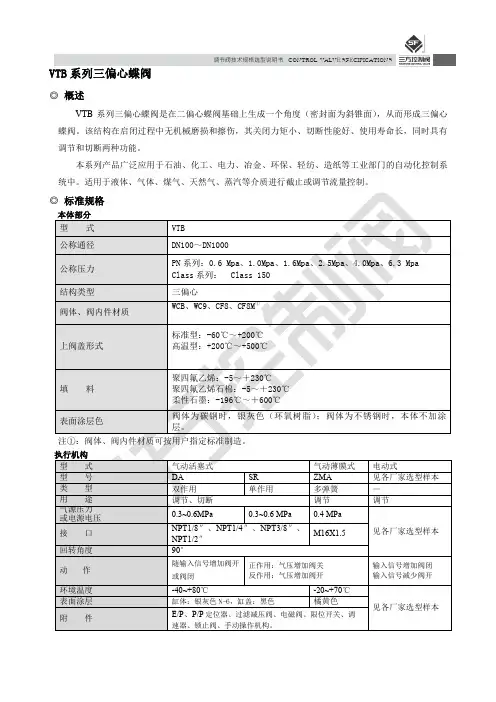
调节阀技术规格选型说明书CONTROL VALVE SPECIFICATIONSVTB系列三偏心蝶阀◎概述VTB系列三偏心蝶阀是在二偏心蝶阀基础上生成一个角度(密封面为斜锥面),从而形成三偏心蝶阀。
该结构在启闭过程中无机械磨损和擦伤,其关闭力矩小、切断性能好、使用寿命长,同时具有调节和切断两种功能。
本系列产品广泛应用于石油、化工、电力、冶金、环保、轻纺、造纸等工业部门的自动化控制系统中。
适用于液体、气体、煤气、天然气、蒸汽等介质进行截止或调节流量控制。
调节阀技术规格选型说明书CONTROL VALVE SPECIFICATIONS·2 ·调节阀技术规格选型说明书 CONTROL VALVE SPECIFICATIONS· 3 ·表1-2本体部分材质:不锈钢调节阀技术规格选型说明书CONTROL VALVE SPECIFICATIONS ◎表5 法兰标准、外形尺寸及重量表5-1:法兰标准注:B*开档尺寸可按用户要求定制。
·4 ·调节阀技术规格选型说明书CONTROL VALVE SPECIFICATIONS表5-3:气动活塞式蝶阀外形尺寸及重量Array·5 ·调节阀技术规格选型说明书CONTROL VALVE SPECIFICATIONS注:表中重量为阀体部位的重量,公称压力为PN16。
注:B*开档尺寸可按用户要求定制。
·6 ·调节阀技术规格选型说明书 CONTROL VALVE SPECIFICATIONS· 7 ·表5-5:气动薄膜式蝶阀外形尺寸及重量(法兰式)调节阀技术规格选型说明书CONTROL VALVE SPECIFICATIONS 表5-6:气动单作用活塞式蝶阀外形尺寸及重量(法兰式)注:表中重量为阀体部位的重量,公称压力为PN16。
注:B*开档尺寸可按用户要求定制。
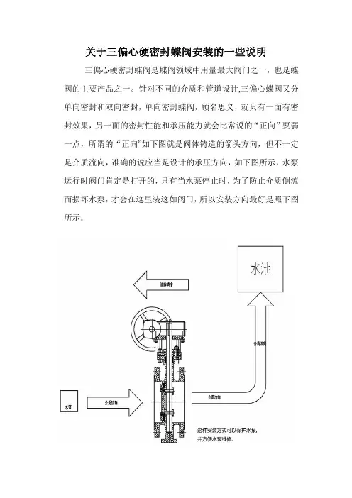
关于三偏心硬密封蝶阀安装的一些说明
三偏心硬密封蝶阀是蝶阀领域中用量最大阀门之一,也是蝶阀的主要产品之一。
针对不同的介质和管道设计,三偏心蝶阀又分单向密封和双向密封,单向密封蝶阀,顾名思义,就只有一面有密封效果,另一面的密封性能和承压能力就会比常说的“正向”要弱一点,所谓的“正向”如下图就是阀体铸造的箭头方向,但不一定是介质流向,准确的说应当是设计的承压方向,如下图所示,水泵运行时阀门肯定是打开的,只有当水泵停止时,为了防止介质倒流而损坏水泵,才会在这里装这如阀门,所以安装方向最好是照下图所示。
但不是所有阀门的介质流向都要与阀体的箭头相反,如下图,这台阀门的作用是为了截断介质,并且肯定没有介质倒流的现象,那安装时就要让介质流向(也就是承压方向)和阀体上铸造的箭头方向相同。
才能让这台阀门的密封性能发挥的更好。
温馨提示:如果管道中介质流向不可操控、或者本来设计的就有可能要介质来回流动,并且还要随时截断介质,双向蝶阀才是你ᴰ好的选择。
这种阀门不仅仅是能双向承压ˈ就密封性能也更有保障。
ѝ⿻䰰䰘ᐕᇔ
2015/9/13。
三偏心蝶阀使用说明书受控本非受控本编制日期 . 审核日期 . 批准日期 .目录1、总则2、用途与技术性能3、阀门结构4、主要零件及材料5、工作原理与结构说明6、阀门运输7、阀门保存8、阀门安装9、阀门操作10、阀门的使用与维修11、阀门可能发生的故障、原因及消除方法12、质量保证13、服务1.总则1.1感谢您选用NEWAY蝶阀。
作为承压设备,阀门具有潜在的压力危险,为您的安全,请先仔细阅读使用说明书,按照推荐的存储、安装、应用及保养方法进行操作。
1.2NEWAY蝶阀设计遵循API609及ASME B16.34。
NEWAY阀门的设计、生产、工厂检验遵照公司的质量保证体系执行,该质量保证体系通过ISO9001验证。
1.3阀门的设计符合行业标准,未考虑所有工况的特定要求。
最终用户或管道系统设计者应选择正确的阀门压力等级、阀门类型、材料、特定场合阀门参数。
用户选择阀门需要考虑以下几点;—工作压力、温度是否超出ASME B16.34要求;—施加在阀门上的外部负荷;—腐蚀度;—磨损量;1.4如果购买条款写明,阀门应按CE/PED要求鉴定与标记。
则CE标记固定在阀门的顶法兰处。
2.用途与技术性能2.1用途蝶阀广泛用于石油、化学、电站和综合类行业,用于管线中的切断、转换、调节。
2.2技术性能设计标准: API609-2004,ASME B16.34-2004法兰标准: ASME B16.5-2003,ASME B16.47-1999结构长度: API609-2004公称通径: 50~1400 mm(2~56")公称压力: 150LB~600LB主要零件与材料:见表四内件材料: ASTM 材料,见表五适用温度:见表六适用介质:见表六阀门试验: API5983.阀门结构见图一、二,主要外形尺寸及连接尺寸见表一、二、三图一图二表一、150LB连接尺寸及外形尺寸a)3”~24”/150LB,WAFER,法兰标准ASME B16.5b)26”~56”/150LB, WAFER,法兰标准ASME B16.47Bc)3”~24”/150LB,LUG,法兰标准ASME B16.5d)26”~56”/150LB, LUG,法兰标准ASME B16.47Be)3”~24”/150LB,RF,法兰标准ASME B16.5f)26”~56”/150LB, RF,法兰标准ASME B16.47B表二、300LB连接尺寸及外形尺寸a)3”~24”/300LB,WAFER,法兰标准ASME B16.5b)3”~24”/300LB,LUG,法兰标准ASME B16.5c)3”~24”/300LB,RF,法兰标准ASME B16.5表三、600LB连接尺寸及外形尺寸a)3”~24”/600LB,WAFER,法兰标准ASME B16.5b)3”~24”/600LB,LUG,法兰标准ASME B16.5c)3”~24”/600LB,RF,法兰标准ASME B16.54.主要零件及材料5.阀门工作原理和结构说明5.1工作原理蝶阀的首要功能是通过手轮或驱动装置旋转蝶板架以控制介质的流量(切断、调节)。
Durco TX3 Triple Offset Butterfly Valve2The TX3 is a high performance triple offset butterfly valve capable of closing with zero leakage. The precision seat and seal are machined at an offset angle creating even seat loading around the entire seat ring and eliminating rubbing between the seat and seal during opening and throttling. This design provides repeatable long-lasting zero leakage shut-off.The Valdisk TX3 high performance design includes the following features:• API 598 Zero Leakage • Robust Sealing Options • Variety of Body Styles • Industry CertificationsFlowserve TX3 Triple Offset Butterfly ValveTX3 Specifications3Solving ApplicationsAPI 598 Zero LeakageTX3 valves have been tested to the industries most stringent seat leak test requirements demonstrating the ability to shut-off with zero leakage. Test standards include:• API 598: Valve Inspection and Testing• MSS SP-68: High Pressure Butterfly Valves with Offset Design • ISO 5208 (EN 12266): Industrial valves – Pressure testing of metallic valves • ANSI/FCI 70-2: Control Valve Seat LeakageRobust Sealing OptionsThe TX3 laminated seal ring provides bubble tight shut-off even in gas applications. Each individual layer performs anindependent sealing a function and is unaffected by the damage to other layers. Additionally, for high temperature applications a solid metal seal ring is available, and for low temperature applications the solid metal seal can be replaced with a PTFE seal ring.Variety of Body StylesTX3 is suited for a range of applications and is available with several different body styles to suit the needs of each application. The valve body can be configured in wafer, lug, double flanged short or long, buttweld, cryogenic, and offset top entry.Industry CertificationsTX3 valves have obtained numerous industry certifications so that the valve can be used around the world. Certifications include:• API 609: Butterfly Valves: Double-flanged, Lug and Wafer-type • PED: Pressure Equipment Directive • TRCU: Technical Regulation Conformity • IEC 61508 (SIL3): Functional Safety of Electronic Safety-related Systems • API 607: Fire Test for Quarter-turn Valves and Valves Equipped with Nonmetallic Seats Note: Not all model configurations meet every certification listed. Contact factory for certification documentation for specific valve models.Wide Range of IndustriesThe TX3 is designed for applications in a wide range of industries including oil and gas, chemical, power generation, andvarious general industries.4Low Emissions Packing: multiple packing options including PTFE, graphite to meet stringent FugitiveEmissions RequirementsFire-safe: tested to meet API 607 requirementsAnti-blowout shaft: required by API 609 and ASME B16.34, ensuring a safe work environment for techniciansTX3 Triple Offset Butterfly Valve – FeaturesVariety of body styles: allows the valve to work in many different applications and provides the option of a smaller lighter body or a longer body that can replace a ball or gate valve without requiring any piping changes.Stellite coated bearings:robust design for ultimatereliabilityTight shut-off: triple offset seat design providesreliable long-lasting zero leakage shut-off suitablefor end of line serviceBottom Flange: allows for easymaintenanceStellite seat surface: longlasting sealing performance56Flowserve offers a comprehensive range of Automax, Norbro, Worcester, and Limitorque actuators and instrumentation, capable of providing complete automated on-off or modulating packages to meet customer requirements. The TX3 is an ideal platform to provide automated valve solutions for a wide variety of application needs.RG ActuatorThe Flowserve RG scotch yoke actuator provides torque outputs to 2.2 million in-lbs, which can handle the full torque requirements of the TX3 range of valves. The RG actuators achieve superior performance by using a robust yoke support system that significantly reduc-es transverse loads. The RG actuators feature modular construction, offering a variety of options including fail direction,pneumatic or hydraulic pressure modules, and several manual override options.SuperNova Rack & Pinion ActuatorThe Flowserve SuperNova rack & pin-ion rotary actuator is designed for reli-ability, versatility, and safety. Rugged, yet compact construction, combined with technical solutions make this prod-uct extremely reliable in the severest ofoperating conditions.Accurate, Easy to Use Process Control -Operated with a robust actuator and precise Logix digital positioner.Automated Valve SolutionInstrumentation and AccessoriesA variety of Flowserve instrumentation components and accessories are available to meet most all automation appli-cations. Instrumentation and accessories products have been developed to provide control to and feedback from actuated valve assemblies. Products include:• Limit switch boxes • Solenoid valves, flow con-trols, NAMUR accessories • Gear Overrides• Auto Brakit mounting kits and SureGrip couplingsLogix Digital PositionersFlowserve Logix digital positioners offer the best in performance, ease of use, and calibration. Several models are available with a variety of features, such as a single push button calibration, LCD display, network communication, and diag-nostic support through ValveSight software.7PNxt! Valve Sizing and SelectionPNxt! Valve Sizing and Selection is the right tool for the right product – first time, every time. This comprehensive set of next generation engineering tools allow you to size and select Flowserve control valve products best suited to your application andservice conditions. In just seconds, you get the answers you need to ensure you make the right choice.ValveSight™ Diagnostic Software – Prevention DeliveredValveSight is a diagnostic solution for control valves that can be seamlessly integrated into a host control and/or plant asset management system. The power of ValveSight is the intelligent diagnostic engine -- which detects an emergingcondition in the valve, actuator, positioner, and control signal -- that may indicate a performance, safety, or environmental problem. ValveSight advises which corrective actions to take toprevent a failure.Flowserve - Solutions to keep you flowingFlowserve is Everywhere You AreFlowserve manufacturing sites and quick response service centers are located all around the world so customers have on-the-spot availability for technical support and experienced field service technicians. Wherever your operations are, Flowserve is there tohelp your operations be successfulUnited States Flowserve1978 Foreman Drive Cookeville, TN 38501USAPhone: +1 931 432 4021Fax: +1 931 432 3105GermanyFlowserve (Ahaus) GmbH Von Braun Strasse 19 a D-48683 Ahaus GermanyPhone: +49 2561 686-0Fax: +49 2561 868-39IndiaFlowserve India Controls Pvt. Ltd.B-8, MMDA Industrial Area,Maraimalai Nagar, Tamil Nadu India 603 0209Phone: +91 44 27452323Fax: +91 44 2745 2327SingaporeFlowserve Pte. Ltd.12 Tuas Avenue 20Republic of Singapore 638824SingaporePhone: +65 6879 8900Fax: +65 6862 4940To find your local Flowserve representative:For more information about Flowserve Corporation, visit or callUSA 1 800 225 6989 or International +1 972 910 0774FCD DVENBR0061-00-AQPrinted in USA. November 2015. © 2015 Flowserve Corporation。
企业简介
上海凯工阀门有限公司地处上海嘉定工业园区,公司占地面积439600平方米,是一家专业设计、制造和销售各种阀门的大型股份制企业。
公司拥有专业的阀门设计、制造工程技术人员,拥有各类机加工设备和试验装置。
公司已通过挪威船级社DNV ISO9001:2000质量管理体系认证、英国UKAS ISO14001环境管理体系认证和美国石油协会API 6D 标准认证。
公司是中国通用机械阀门行业协会的会员单位,中石油、中海油、中石化的战略合作企业,化工装备定点生产企业,是中国城市燃气协会会员单位。
公司的产品有闸阀、截止阀、止回阀、蝶阀、球阀及高温炼化、炼油、炼焦、长输管线、油田、电站高压等阀门。
产品的公称压力从PN1.0~80MPa ,公称通径DN15~2500mm ;温度从-196℃~600℃。
产品采用的标准有GB 、JB 、API 、ANSI 、JIS 、BS 、DIN 等。
三偏心金属密封蝶阀系列是我公司主要产品,大量使用在冶金、轻工、电力、石油化工、煤气水道等领域。
上海凯工以“发掘尖端阀门技术,竭尽全力回报用户”作为企业的经营理念,以给用户提供优质产品和满意服务为己任,不断地进行自身变革,力争成为中国阀门行业的明珠企业。
一、特点及用途:
该阀门采用三偏心金属密封结构,在室温或高温下均具有良好的密封性能,与同规格闸阀或截止阀相比,体积小,重量轻,启闭灵活,使用寿命长,广泛适用于冶金、轻工、电力、石油化工、煤气水道等领域,使用安全可靠,该阀门是现代化企业最理想的选择。
二、标准规范:
D343H-16C/25 D373H-16C/25按照下列标准执行
1.设计制造与检验按照JB/T8527-1997规定。
2.法兰连接尺寸按GB911
3.3-88;GB9113.4-88的规定。
3.结构长度按GB12221-89的规定。
4.阀门压力试验按GB/T13927-92的规定。
D343H-150Lb D373H-150Lb 按照下列标准执行
1.设计制造与检验按照API 609规定。
2.法兰连接尺寸按API 609的规定。
3.结构长度按API 609的规定。
4.阀门压力试验按API 598的规定。
五、三偏心金属密封蝶阀的密封原理:图1为本公司生产的典型三偏心金属密封蝶阀密封副结构简图。
(1)结构特征。
蝶板回转中心(即阀门轴中心)与蝶板密封面形成一个尺寸A偏置,并与阀
体中心线形成一个B偏置;阀体密封面中心线与阀座中心线(即阀体中心线)形成一个
角度为β的角位置。
(2)密封原理。
由于在双偏心密封蝶阀的基础上,将阀座中心线再与阀体中心线形成一
个β角位置,其偏置后的结果由图2的A-A剖视图可见,当三偏心密封蝶阀处于
完全开启状态时,其蝶板密封面会完全脱离阀座密封面,并且在蝶板密封面与阀体
密封面之间形成一个与双偏心密封蝶阀相同的间隙Y,而由图3可见,由于β角位
置的形成会使长、短半径转动的蝶板大、小半圆上,蝶板密封面转动轨迹的切线与
阀座密封面形成一个θ1和θ2角。
使蝶板启闭时蝶板密封面相对于阀座密封面渐出
脱离和渐入压紧,从而彻底消除了蝶板启闭时蝶阀密封副两密封之间的机械磨损和
擦伤。
该阀门从0°~90°开启时,蝶板的密封面会在开启瞬间立即脱离阀座密封面,在其90°~0°关闭时,只有在关闭的瞬间,其蝶板密封面才会接触并压紧阀座密封
面。
由图2可见,由于θ1、θ2角的形成,使蝶阀关闭时,其密封副两密封面之间
的密封比压可以由常规蝶阀的阀座弹性产生改为外加于阀门轴的驱动转矩产生,不
仅消除了常规蝶阀中弹性阀座弹性材料老化、冷流、弹性失效等因素造成的密封副
两密封面之间的密封比压降低和消失,而且可以通过对外加驱动转矩的改变实现对
其密封比压的任意调整,从而使三偏心蝶阀的密封性能和使用寿命得到大大的提高。
图1 三偏心金属密封蝶阀
图3 三偏心金属密封蝶阀关闭状态图
六、阀门的主要外形尺寸、连接尺寸及重量见附图4:
图4 法兰连接三偏心金属密封蝶阀结构外形图
图5 对夹式三偏心金属密封蝶阀结构外形图
型三偏心金属密封蝶阀
上海凯工阀门有限公司
D373H-150Lb D373H-16C/25
D343H-150Lb D343H-16C/25。