testo104温度计说明书
- 格式:pdf
- 大小:686.99 KB
- 文档页数:12
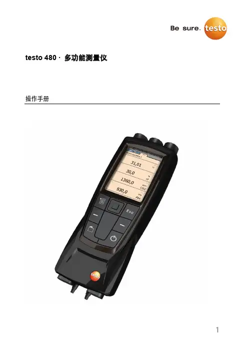
1testo 480 · 多功能测量仪操作手册2目录2 安全和环境 (5)2.1. 本文介绍 (5)2.2. 保证安全 (6)2.3. 保护环境 (7)3 规格 (8)3.1. 使用 (8)3.2. 技术数据 (8)4 产品说明 (11)4.1. 综述 (11)4.1.1. 便携式仪器 (11)4.1.2. 仪器接口 (12)4.1.3. 操控按键 (13)4.1.4. 显示屏 (14)5 入门知识 (16)5.1. 调试 (16)5.2. 产品 (19)5.2.1. 菜单 (19)5.2.2. 选择功能 (20)5.2.3. 退出菜单 (20)5.2.4. 切换到另外一个标签 (20)5.2.5. 输入数值 (20)5.2.6. 保存数值 (21)6 使用产品 (22)6.1. 设置操作 (22)6.2. 设置测量页面 (23)6.2.1. 计算的测量参数 (24)6.3. 收藏夹标签 (25)6.4. 探头菜单 (25)6.5. 数据管理浏览器菜单 (27)36.6. 测量和测量程序 (30)6.6.1. 保留(“保持”)测量数值 (30)6.6.2. 测量程序 (30)6.6.3. 栅格测量 (32)6.6.4. 紊流度测量 (36)6.6.5. 皮托管测量 (37)6.6.6. 使用风量罩测量 (38)6.6.7. 压力测量 (38)6.6.8. 二氧化碳测量 (39)6.6.9. 保存测量值 (40)6.6.10. 打印测量值 (41)6.6.11. 测量数值导出 (43)7 维护产品 (44)7.1.1. 电池护理 (44)7.1.2. 进行湿度调整 (44)7.1.3. 仪器固件更新 (45)8 提示和帮助 (51)8.1. 问题和解答 (51)8.2. 附件和备件 (52)42 安全和环境2.1. 本文介绍符号和书写标准警告一定要注意带有如下警告符号的信息,并采取规定的预防措施。
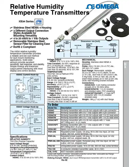
Dimensions: mm (inch)Hu-32wall mounting bracket, and operator’s manual.Ordering Example: HX94C, duct mount RH/temperature transmitter with 4 to 20 mA output.HX94C Current Hook-Up MECHANICAL Housing: Stainless steel NEMA 4 enclosure Probe: 254 x 19 mm (10 x 0.75") dia., 305 mm (12") cable Duct Flange: Removable, variable 25.4 to 227 mm (1 to 9") depth; 70 mm (2.75") dia., duct hole 21 mm (0.812") dia.4 mtg holes. 4 mm (0.156") dia. (for #6sheet metal screws) on 51 mm (2.00") dia. circle; wall mounting bracket included Connections:HX94C/94V: 4 pin mating connector accepts 26 to 18 AWG wires HX94CW/94VW: 1 m (3') braidedand shielded cable, PVC sheathingHX94CNPT/94VNPT: 1⁄2" male NPTconductor with 1 m (3') braided/ shielded cable Weight: 198 g (7 oz) with duct flange HX94 SeriesSpecifications RELATIVE HUMIDITY Thin-Film Polymer Capacitor Input Voltage Range: 6 to 30 Vdc, (polarity protected)Range/Accuracy/Repeatability: 3 to 95% RH/±2% RH/±1% RH Temperature Compensation: -20 to 85°C (4 to 185°F)Current Output: HX94C: 4 to 20 mA (0 to 100% RH)HX94V: 0 to 1.0 V (0 to 100% RH)Time Constant: (for 90% response at 25°C; in moving air, 1m/sec.) Less than 20 seconds, 10 to 90% RH Less than 30 seconds, 90 to 10% RH TEMPERATURE Thin-Film 100 Ω Platinum RTD (DIN 43760)Input Voltage Range: 6 to 30 Vdc, (polarity protected)Range: 0 to 100°C (32 to 212°F)Accuracy: ±0.6°C (±1°F)Repeatability: ±0.3°C (±0.5°F)Current Output: HX94C: 4 to 20 mA for 0 to 100°C Voltage Output: HX94V:0 to 1.0V for 0 to 100°C Time Constant: (for 60% response) Less than 2 sec in moving air U Stainless Steel NEMA 4 HousingU 3 Different Output Connection Styles Available for Mounting VersatilityU 4 to 20 mA/0 to 1 Vdc OutputsU Removable Stainless Steel Sensor Filter for Cleaning EaseU RoHS 2 CompliantRelative Humidity Temperature Transmitters The HX94 relative humidity/ temperature transmitter provides a reliable and low cost method for duct mount monitoring applications. Solid state sensors provide excellent sensitivity, fast response, and stability. Simple hookup and linearized output permit interfacing with most display and control devices.。
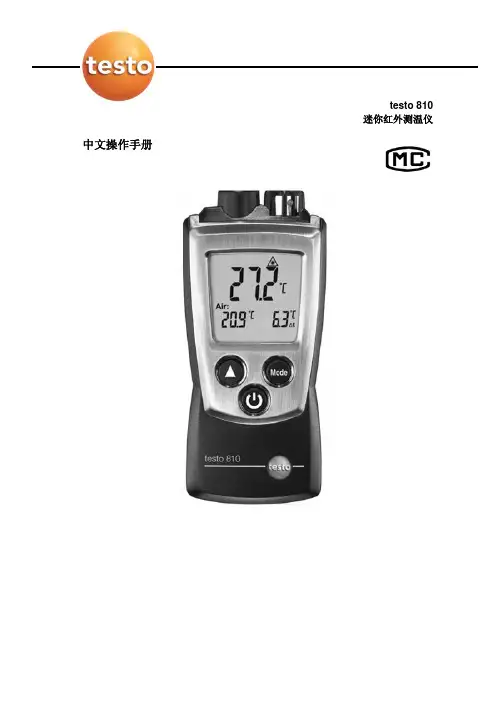
testo 810迷你红外测温仪中文操作手册产品描述①保护帽:安装位置②红外传感器③空气温度传感器④显示屏⑤控制按钮⑥电池盒(在仪器背面)基本设置关机 > 按键2秒 > 按选择键()> 按确认键()温度单位:°C, °F > 温差Δt: OFF(关),On(开)>发射率:ε> 自动关机:OFF(关),On(开)开机按住打开背光灯(按住10秒)在仪器打开的情况下,按住IR(红外)测量持续按键选择显示模式在仪器打开的情况下,用键来选择HOLD:读数被锁定了 > MAX:最大值 > MIN:最小值关闭仪器在仪器开着的情况下,按住2秒安全和环保提示¾请在使用本产品之前,仔细通读该操作手册,并熟悉本产品的操作。
请小心保管本文档,以便你在需要时可以查阅。
请把该操作手册提供给其他用户阅读。
¾请特别注意下列标识的提示信息:重要提示!避免人身伤害或仪器损坏的预防措施¾请在操作手册规定的用途范围,以及限定的技术参数内,正确操作仪器。
不要使用强力。
¾不要将仪器与溶剂、硫酸以及其他腐蚀性溶液存放在一起。
¾请务必按照操作手册中的描述来执行维护和修理工作。
请遵循规定的步骤。
为了确保仪器安全,请务必使用德图的原装备件。
环保回收¾将损坏的充电电池/废电池送到指定的电池回收点。
¾在仪器使用寿命结束时,将其寄回德图。
我们将保证以环境友好的方式处置这些产品。
规格和参数说明Testo 810是一款红外测量仪器,常用于测量表面温度,如散热器和发热器,同时测量周围的空气温度。
技术数据测量数据常规仪器数据·传感器:红外传感器NTC空气温度传感器·参数:°C, °F·量程:红外测温: -30~300°C, -20~575°F, 空气温度: -10~50°C, 14~122°F ·分辨率:0.1°C,0.1°F ·保护等级:IP 40·环境温度:-10~+50, +14℃~+122℉·存放/运输温度:-40~+70,℃-40~+158℉·电源:2节1.5V AAA电池·电池寿命:50小时(背光灯关闭)·尺寸:119×46×25 mm·重量:90g(包括电池和保护帽)·精度:红外测温:±2 °C(-30~+100°C)±3.6 °F(-22~212°F)±2 %测量值(其余量程)空气温度:±0.15°C;±0.9°F 标准和规范·EC标准:89/336/EEC·测量速率0.5 秒·光学分辨率6:1 保修保修期: 1 年保修条款:见保修卡产品描述概述①保护套:安装位置②红外传感器③空气温度传感器④显示屏⑤控制按钮⑥电池盒(在仪器背面)初始步骤¾安装电池1. 向下推动电池盒盖,打开电池盒2. 放入电池(2节1.5V AAA电池)。
testo 830-T1 (0560 8311) testo 830-T2 (0560 8312)91. General Information Please read this document through carefully and familiarise yourself with the operation of the product before putting it to use.Keep this documentation to hand so that you can refer to it when necessary.2. Product Description3. Safety InformationContact measurement: Do not measure on or near live parts. Infrared measurement: Please adhere to the required safe distance when measuring on live parts.Operate the instrument properly and according to its intended purpose and within the parameters specified. Do not use force.Do not expose to electromagnetic radiation (e.g. microwaves,induction heating systems), static charge, heat or extreme fluctuations in temperature.Do not store together with solvents (e.g. acetone).Open the instrument only when this is expressly described in the documentation for maintenance purposes.Laser radiation! Do not look into laser beam. e n Accessories Name Item no.Water-tight immersion/penetration probe, -60 to +400°C/-76 to +752°F 0602 1293Quick-reaction surface probe, -60 to +300°C/-76 to +572°F 0602 0393Robust air probe, -60 to +400°C/-76 to +752°F 0602 1793Leather protection sleeve 0516 8302Emissivity adhesive tape ε=0.950554 0051Infrared sensor,laser Battery compartment DisplayOn/Off switch Contact measurement Measurement button:infrared measurement Infrared measurementProbe socket (testo 830-T2 only)10Ensure correct disposal:Dispose of defective rechargeable batteries and spentbatteries at the collection points provided.Send the instrument directly to us at the end of its life cycle.We will ensure that it is disposed of in an environmentallyfriendly manner.4. Intended Usetesto 830 is a compact infrared thermometer for the non-contact measurement of surface temperatures. Using testo830-T2, it is possible to carry out additional contact measurements byattaching probes.5. Technical DataFeature testo 830-T1testo 830-T2Parameter°C/°FInfrared measurement range-30 to +400°C/ -22 to +752°FInfrared resolution0.1°C/0.1°FInfrared accuracy±1.5°C/ 2.7°F or 1.5% of reading (+0.1 to +400°C/ +32 to +752°F)1;(at 23°C) +/- 1 digit±2°C/ 3.6°F or 2% of reading (-30 to 0°C/ -22 to +31.9°F)1Emissivity0.1 to 1.0 adjustableInfrared measurement rate0.5sTemp. sensor -Thermocouple Type K (attachable) Measurement range of temp sensor--50 to +500°C/ -58 to +932°F Resolution of temp. sensor-0.1°C/ 0.1°FAccuracy of temp. sensor-±0.5°C/0.9°F+0.5% of reading (±1 digit)at rated temperature 22°C/ 72°F Measuring rate of temp. sensor- 1.75sOptics (90% value)10:1212:12Laser type 1 x laser 2 x laserOperating temperature-20 to +50°C/ -4 to +122°FTransport /S torage temperature-40 to +70°C/ -40 to +158°FPower supply9V block batteryBattery life 20 h 15 hHousing ABSDimensions (LxHxB)190 x 75 x 38mm/ 7.5 x 3.0 x 1.5inCE guideline2004/108/EECWarranty 2 yearsLaserLaser type 1 x laser 2 x laserPower< 1 mWWavelength645 to 660 nmClass2Standard DIN NE 60825-1:2001-111the larger value applies2+ Opening diameter of the sensor (16mm/ 0.6in)6. Initial OperationInsert battery: See 9.1Changing the battery.117. Operation7.1 Connecting probe (testo 830-T2 only)Connect temperature probe to probe socket. Observe +/-!7.2 Switching on/offSwitch on instrument: Press measurement button.-lights up).The display light remains for 10 seconds every time a button is activated.pressed until display darkens.The device switches off automatically after 1 min (IR measure -ment view) or 10 mins (contact measurement view, only testo830-T2) without the button being pressed.7.3 Measuring/ measurement, this is done when the device is switched off orwhen you switch to the IR measurement view.-The instrument is switched on.Infrared measurement1Start measurement: Hold down measurement button.2Locate object to be measured using laser point.testo830-T1: laser marks the centre point of the measurement spot.testo830-T2: Laser marks the upper and lower end of themeasurement spot.-The current reading is shown (2 measurements per second)3End measurement: Release button.-HOLD lights up. The last measured value and min./max. value are saved until the next measurement.Restart measurement: Press measurement button.Contact measurement (testo 830-T2 only)-Temperature probe was connected before the measuring instrument was switched on.1-The instrument changes to the contact measurement mode (lights up). The current reading is shown.en122End the measurement: Press .-HOLD lights up. The last measured value and min./max. value are saved until the next measurement.Switch between min., max. and recorded value: Press .Restart measurement: Press .Back to infrared measurement view: Press measurementbutton.Setting the emissivity-Instrument is in the infrared measurement mode.If no button is pressed for 3 s in the emissivity mode, theinstrument switches to the infrared measurement mode.1Press for 3 s.2Set emissivity: Press or-The instrument switches to the infrared measurement mode.8. Settings-Instrument is switched off.If no button is activated in the setting mode for 3 s, theinstrument changes to the next mode.1Press for 3 s.-The device switches to settings mode.2Set lower alarm value (ALARM): Press or . Hold the button down to go forward quickly.3Set upper alarm value (ALARM): Press or . Hold the button down to go forward quickly.4Set alarm function on/oFF: Press or .5Select parameter (°C/ °F) : Press or .-The device returns to IR measurement view.The alarm function is only available for IR measurement. If theset alarm values are exceeded/not reached, a visual andacoustic alarm is output.9. Service and Maintenance9.1 Changing the batteryInstrument must be switched off!1Open battery compartment:Open up cover.2Remove used battery and insert newone. Observe +/-. The minus should bevisible once the battery is inserted.3Close battery compartment: Closecover.139.2 Clean instrument Do not use abrasive cleaning agents or solutions.Clean the housing with a damp cloth (soap water).Carefully clean the lens with water or cotton buds dipped in water or medical alcohol. 10. Questions and AnswersQueryPossible causes Possible solutionInfrared measurement mode: -Readings outside -- - -lights up.measurement range.Contact measurement mode: -Readings outside -If we have not answered your question, please contact your local distributor or Testo´s Customer Service.11. Information on infrared measurement 11.1 Measurement methodInfrared measurement is an optical measurementKeep lens clean.Do not measure with clouded lens.Keep measurement field (area between instrument and object being measured) free of interferences: no dust and dirtparticles, no moisture (rain, steam) or gases.Infrared measurement is a surface measurementIf there is dirt, dust, frost etc. on the surface, only the top layer will be measured, i.e. the dirt.In the case of shrinkwrapped foodstuffs, do not measure in air pockets.If values are critical, always subsequently measure using a contact thermometer. Particularly in the food sector, the core temperature should be measured with a penetration/immersion thermometer.Adaptation timeIf the ambient temperature changes (change of location, e.g.inside/outside measurement) the instrument needs an adaptation time of 15 minutes for infrared measurement.e n1411.2 EmissivityMaterials have different emissivities, i.e. they emit different levels of electromagnetic radiation. The emissivity of testo 830 is set in the factory to 0.95. This is the ideal value for measuring non-metals (paper, ceramics, plaster, wood, paints and varnishes),plastics and foodBright metals and metal oxides are only suited to a limited extent to infrared measurement on account of their low or nonuniform emissivity.Apply emissivity enhancing layers such as varnish or emission adhesive tape (Item no. 05540051) to the object being measured. If this is not possible, measure with the contact thermometer.Emissivity table of the most important materials(typical values)A specific spot is determined depending on the distance from the measuring instrument to the object being measured. Measurement optics (Ratio Distance : Measurement spot)500 mm1000 mm2000 mm5000 mmØ 516 mmØ 216 mmØ 116 mmØ 66 mmØ 16 mm testo 830-T1laser1512. Information on contactmeasurementObserve minimum penetration depth in immersion/penetration probes: 10 x probe diameterAvoid applications in corrosive acids or bases.Do not use spring-loaded surface probes on sharp edges.e n 500 mm 1000 mm2000 mm 5000 mm Ø 433 mm Ø 183 mmØ 100 mmØ 58 mm Ø 16 mm testo 830-T2laserlaser。
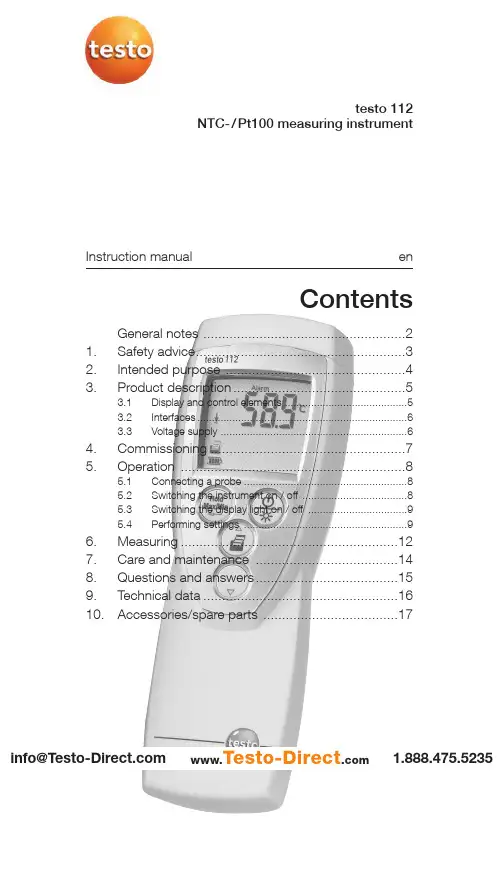
Instruction manual entesto 112NTC-/Pt100 measuring instrumentContentsGeneral notes ......................................................21.Safety advice........................................................32.Intended purpose ................................................43.Product description. (5)3.1Display and control elements ..........................................53.2Interfaces........................................................................63.3Voltage supply . (6)4.Commissioning ....................................................75.Operation (8)5.1Connecting a probe ........................................................85.2Switching the instrument on / off ....................................85.3Switching the display light on / off ..................................95.4Performing settings .. (9)6.Measuring..........................................................127.Care and maintenance ......................................148.Questions and answers......................................159.Technical data....................................................1610.Accessories/spare parts (17)1.888.475.5235*********************www.Testo-Direct .comGeneral notes2General notesThis chapter provides important advice on using this documentation.The documentation contains information that must beapplied if the product is to be used safely and efficiently.Please read this documentation through carefully andfamiliarise yourself with the operation of the product beforeputting it to use. Keep this document to hand so that youcan refer to it when necessary.Identificationachieved via the steps described.Where steps are numbered,you must always follow the order given!Condition A condition that must be met if an action is to be carried out as described.i ,1,2,...Step Carry out steps.Where steps are numbered,you must always follow the order given!TextDisplay text Text appears on the instrument display.Control buttonPress the button.-ResultDenotes the result of a previous step.ºCross-reference Refers to more extensive or detailedinformation.Button 1.888.475.5235*********************www.Testo-Direct .com1. Safety advice31.Safety adviceThis chapter gives general rules which must be followedand observed if the product is to be handled safely.Avoid personal injury/damage to equipmenti Do not use the measuring instrument and probes tomeasure on or near live parts.i Never store the measuring instrument/probes togetherwith solvents and do not use any desiccants.Product safety/preserving warranty claimsi Operate the measuring instrument only within theparameters specified in the Technical data.i Always use the measuring instrument properly and for itsintended purpose. Do not use force.i Do not expose handles and feed lines to temperatures inexcess of 70 °C unless they are expressly permitted forhigher temperatures.Temperatures given on probes/sensors relate only tothe measuring range of the sensors.i Open the instrument only when this is expresslydescribed in the documentation for maintenance andrepair purposes.Carry out only the maintenance and repair work that isdescribed in the documentation. Follow the prescribedsteps when doing so. For safety reasons, use onlyoriginal spare parts from Testo.Ensure correct disposali Take faulty rechargeable batteries/spent batteries to thecollection points provided for them.i Send the product back to Testo at the end of its usefullife. We will ensure that it is disposed of in an*********************environmentally friendly manner. 1.888.475.52352. Intended purpose42.Intended purposeThis chapter gives the areas of application for which theproduct is intended.Use the product only for those applications for which it wasdesigned. Ask Testo if you are in any doubt.testo 112 is a compact, accurate measuring instrument formeasuring temperatures by means of plug-in temperatureprobes. Thanks to the possibility of connecting not onlyNTC probes, but also Pt100 probes, the testo 112 coversa wide measurement range and at the same time providesa high level of measurement accuracy.The following components of the product are designed for continuouscontact with foodstuffs in accordance with the regulation(EC) 1935/2004:The measurement probe up to 1 cm before the probe handle or theplastic housing. If provided, the information about penetration depthsin the instruction manual or the mark(s) on the measurement probesshould be noted.The product was designed for the followingtasks/applications:·Food sector·Laboratories·Applications requiring official calibration (only relevant forGermany):The testo 112 is approved for official calibration by thePhysikalisch-Technisches Institut PTB (nationalmetrology institute in Germany).Approval mark:The product should not be used in the following areas:·Areas at risk of explosion·Diagnostic measurements for medical purposes*********************1.888.475.52353. Produktbeschreibung 53.Product descriptionThis chapter provides an overview of the components of the product and their functions.3.1Display and control elementsOverviewInfrared interface, probe socket Display Control buttons Battery compartment (rear)Button functionsButton Functions Switch instrument on; switch instrument off (press and hold)In configuration mode: 1.888.475.5235*********************www.Testo-Direct .com3. Production description6Important displayscharged3.2InterfacesInfrared interfaceMeasurement data can be sent to a Testo printer via theinfrared interface on the head of the instrument.Probe socketA plug-in measuring probe can be connected via the probesocket on the head of the instrument.3.3Voltage supplyVoltage is supplied by means of a 9V monobloc battery(included in delivery) or rechargeable battery. It is notpossible to run the instrument from the mains supply orcharge a rechargeable battery in the instrument.*********************1.888.475.52354. Commissioning7missioningThis chapter describes the steps required to commissionthe product.²Removing t t he p p rotective f f ilm o o n t t he d d isplay:i Pull the protective film off carefully.²Inserting a a b b attery/rechargeable b b attery:1To open the battery compartment on the rear of theinstrument, push the lid of the battery compartment inthe direction of the arrow and remove it.2Insert a battery/rechargeable battery (9V monobloc).Observe the polarity!3To close the battery compartment, replace the lid ofthe battery compartment in position and push itagainst the direction of the arrow.*********************1.888.475.52355. Operation85.OperationThis chapter describes the steps that have to be executed frequently when using the product.5.1Connecting a probePlug-in probesPlug-in probes must be connected before the measuringinstrument is switched on so that they are recognised bythe instrument.i Insert the connector of the probe into the probesocket.5.2Switching the instrument on /off²Switching tt he i i nstrument o o n: i Press .- A segment test is carried out: All LCD-segments inthe display briefly light up.- A function test of the instrument and the probe is carried out. The instrument tests the entire measurement channel regarding the adherence to allowed margins of error.The type of probe attached is displayed for approx.2s (NTC or Pt 100).An error is detected:-rEF Error is displayed for approx. 2s, then ----- is displayed. Please contact your dealer or Testo customer service.The function test was successful:-Measurement view is opened: The current reading is displayed.1.888.475.5235*********************www.Testo-Direct .com5. Operation9²Switching t t he i i nstrument o o ff:i Press and hold (for approx. 2s) until the displaygoes out.5.3Switching the displaylight on/off²Switching t t he d d isplay l l ight o o n/off:The instrument is switched on.i Press .5.4Performing settings1To o o pen c c onfiguration m m ode:The instrument is switched on and is in measurementview. Hold, Max or Min are not activated.i(for approx. 2s) until the displaychanges.-The instrument is now in configuration mode.(for approx. 2s) until thechanges that have already been made in configurationmode will be saved.2To s s et t t he a a larm f f unction:Configuration mode is opened, ALARM is lit.1/and confirm·oFF: Switches the alarm function off.·on: Switches the alarm function on.oFF was selected:ºContinue with objective T O SET THE MAX./MIN. PRINTFUNCTION.1.888.475.5235 *********************5. Operation10on was selected:2to set the value for the upper alarm3to set the value for the lower alarm3To s s et t t he m m ax./min. p p rint f f unction:MaxMin is flashing.i/and confirm·on: Maximum and minimum values are printed outas well when current or recorded readings areprinted.·oFF: Maximum and minimum values are not printedout as well when current or recorded readings areprinted.4To s s et A A uto O O ff:Configuration mode is opened, AutoOff is flashing.i/and confirm·on: The measuring instrument switches offautomatically if no button is pressed for 10min (Holdor Auto Hold is lit).·oFF: The measuring instrument does not switchitself off automatically.5To s s et t t he d d ate/time:Configuration mode is opened, YEAR is lit.1to set the current YEAR and confirm2to set the other values for the month() and time (TIME) and confirm each*********************1.888.475.52355. Operation116To s s et t t he u u nit o o f m m easurement:Configuration mode is opened, UNIT is lit.i/7To r r eset:Configuration mode is opened, RESET is lit.i and confirm·no: Instrument is not reset.·Yes: Instrument is reset. The instrument is reset tothe factory settings.The setting of date/time is not reset.-The instrument returns to measurement view.e1.888.475.5235 *********************6. Measuring126.MeasuringThis chapter describes the steps that are required toperform measurements with the product.²Taking a a m m easurement:The instrument is switched on and is in measurementview.i Put the probe in position and read off the readings.With the alarm function on and if the alarm thresholdis exceeded or undershot:-flashes and a signal tone is given.-The alarm goes out if the reading goes below theupper or above the lower threshold again.²Holding t t he r r eading, d d isplaying t t he m m aximum/minimumvalue:The current reading can be recorded. The maximum andminimum values (since the instrument was last switchedon) can be displayed.i several times until the desired value is-The following are displayed in turn:·Hold: the recorded reading·Max: Maximum value·Min: Minimum value·The current reading-In addition to the maximum or minimum readings,the 2nd reading line shows the current reading.*********************1.888.475.52356. Measuring 13²Resetting tt he m m aximum/minimum v v alues: The maximum/minimum values of all channels can be reset to the current reading.1several times until Max or Min lights up.2-All maximum or minimum values are reset to the current reading.²Printing rr eadings: The readings shown on the display (current reading,recorded reading or max./min. reading) can be printed out.A Testo printer is required (accessory part).With the Max./Min. print function switched on, the maximum and minimum values are printed out as well as the current reading or recorded reading.ºSee the chapter P ERFORMING SETTINGS .1Configure the instrument so that the value to beprinted is shown on the display.2-·The measurement value ·The date and timeOnly relevant for applications requiring official calibration in Germany:·A protocol line with the text:Der ausgedruckte Messwert stimmt mit der Anzeige des geeichten Messgeräts überein . (The printed measurement value corresponds to the display of the officially calibrated measuring instrument.)·A signature line1.888.475.5235*********************www.Testo-Direct .com7. Care and maintenance147.Care and maintenanceThis chapter describes the steps that help to maintain thefunctionality of the product and extend its service life.±Cleaning t t he h h ousing:i Clean the housing with a moist cloth (soap suds) if itis dirty. Do not use aggressive cleaning agents orsolvents!±Changing t t he b b attery/rechargeable b b attery:The instrument is switched off.1To open the battery compartment on the rear of theinstrument, push the lid of the battery compartment inthe direction of the arrow and remove it.2Remove the spent battery/rechargeable battery andinsert a new battery/rechargeable battery(9V monobloc). Observe the polarity!3To close the battery compartment, replace the lid ofthe battery compartment in position and push itagainst the direction of the arrow.*********************1.888.475.52358. Questions and answers15 8.Questions and answersThis chapter gives answers to frequently asked questions.Question Possible causes Possible solutionis lit (bottom right·Instrument battery is ·Replace instrumentin display).almost spent.battery.Instrument switches ·Auto Off function ·Switch function off.itself off automatically.is switched on.·Residual capacity ·Replace battery.of battery is too low.Display:-----·Probe is not plugged in.·Switch instrument off,connect probe andswitch instrumentback on again.·Probe break.·Please contact yourdealer or TestoCustomer Service.Display reacts slowly·Ambient temperature ·Raise ambientis very low.temperature.Display: uuuuu·Permitted measuring ·Keep to permittedrange was undershot.measuring range.Display: ooooo·Permitted measuring ·Keep to permittedrange was exceeded.measuring range.Display: rEF Error·Reference measurement·Please contact yourout of tolerance of dealer or Testo±0.1°C Customer Service.If we are unable to answer your question, please contactyour dealer or Testo Customer Service. Contact details canbe found on the guarantee card or on the Internet under.*********************1.888.475.52359. Technical data169.T echnical dataInstrumentCharacteristic ValueParameters Temperature (°C/°F)Measuring range Pt100 probe: -50...+300°C / -58...+572°FNTC probe: -50...+120°C / -58...+248°FResolution0.1°C / 0.1°FAccuracyºSee S YSTEM ACCURACYProbe1x mini DIN socket for Pt100 or NTC temperature probeMeasuring rate2/sOperating temperature range-20...+50°C / -4...+122°FStorage temperature-30...+70°C / -22...+158°FVoltage supply1x 9V monobloc battery/rech. batteryBattery life approx. 70hProtection class with TopSafe (accessory part) and probe connected:IP65EC Directive89/336/EECWarranty 2 yearsSystem accuracyMeasuring range Instrument Probe SystemMeasuring instrument + NTC temperature probe-50.0°C...-25.1°C±1%of reading±0.7%of reading±1.8%of reading-25.0...+40.0°C±0.2°C±0.2°C±0.5°C+40.1...+80.00°C±0.3°C±0.4°C±0.8°C+80.1...+120.0°C±0.5°C±0.6°C±1.2°CMeasuring instrument + Pt100 temperature probe-50.0...-25.1°C±0.2°C±0.3°C±0,6°C-25.0...+40.0°C±0.2°C±0.2°C±0.5°C+40.1...+140.0°C±0.2°C±0.4°C±0.7°C+140.1...+200.0°C±0.2°C±0.6°C±0.9°C+200.1...+300.0°C±0.3°C±0.8°C±1.2°C*********************1.888.475.523510. Accessories/spare parts17 10.Accessories/sparepartsName Part no.NTC probesWater-proof NTC immersion/penetration probe0613 1212Water-proof NTC surface probe for smooth surfaces0613 1912Efficient, robust air probe, NTC0613 1712Pt100 probesRobust, water-proof Pt100 immersion/penetration probe0609 1273Efficient, robust air probe, Pt1000609 1773MiscellaneousTopSafe testo 112, protects from impact and dirt particles0516 0221For a complete list of all accessories and spare parts,please refer to the product catalogues and brochures orlook up our website: *********************1.888.475.5235Notes18*********************1.888.475.5235Notes19*********************1.888.475.52350977.1121/02/T/dr/14.03.2006w w w .t e s t o .c o mtesto AGPostfach 1140, 79849 Lenzkirch Testo-Straße 1, 79853 Lenzkirch Telefon: (07653) 681-0Fax: (07653) 681-100E-Mail:*************Internet: 1.888.475.5235*********************www.Testo-Direct .com。
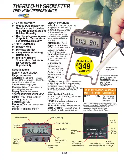
DISPLAY FUNCTIONSIndication: Continuous, for both temperature and humidity Min/Max: Storage of high and low readings for both temperature and humidity; user reset to clear stored values at any timeANALOG OUTPUTS Types: 10 mV/°F and 10 mV/%RH, continuous output; connected to >47 k ΩimpedanceConnections:Standard banana plug; common ground connector for both outputsMECHANICAL Dimensions:180 x 81 x 60 mm(7.1" x 3.2" x 2.4")Probe: 12.7 mm x 76.2 mm (0.5" x 3")Weight: 400 g (14 oz)Display: 11 mm (0.42") LCD readout;3-digit temperature, 2-digit humidity indication; custom indicators formax, reset, display hold and low battery)Meter Ambient Conditions:10 to 40°C (50 to 104°F); 0-90% RH,non-condensingPower: 9 V battery included and110 Vac adaptor included Battery Life: 100 h, alkaline battery Sleep Mode: Unit shuts off after 15minutes if no buttons are pushed. SpecificationsHUMIDITY MEASUREMENT Range: 2 to 98% RHAccuracy: 3% @ 25°C, between 20 and 90% of range; 5% @ 25°C,below 20% or above 90%Sensor: Resistive polymerResponse Time: 30 seconds for a 30 to 80% step changeDisplay Resolution: 1% RHTEMPERATURE MEASUREMENT Range: -17 to 48°C; 2 to 120°F Accuracy: 0.5°C/1°F Sensor: Solid stateResponse Time: 3 m for 63% step changeDisplay Resolution: 1°C/1°Fߜ3-Year WarrantyߜUnique Dual Display forSimultaneous Indication of BOTH Temperature andRelative HumidityߜDual Simultaneous AnalogOutputs for Temperature and Relative Humidity ߜ°C/°F Switchable ߜDisplay Hold ߜMin/Max StorageߜSleep Mode to ProlongBattery LifeߜDigital % RH andTemperature Calibration for Accuracy and Repeatability THERMO-HYGROMETERVERY HIGH PERFORMANCEU.S. Patented D316,053;4,949,274; 4,864,226/Canada 1,288,818/Germany DE3879889T2/Italy 0318549/Japan-Pending/UK0318549Shown slightly larger thanactual size Model RH411$349Basic Unit *RH411 supplied with handheld temperature/humidity sensor with 5' cable, 9 V battery, 110V ac adaptor and operator’s manual.Ordering Example: RH411 digital temperature/humidity indicator $349.CANADA www.omega.ca Laval(Quebec) 1-800-TC-OMEGA UNITED KINGDOM www. Manchester, England0800-488-488GERMANY www.omega.deDeckenpfronn, Germany************FRANCE www.omega.frGuyancourt, France088-466-342BENELUX www.omega.nl Amstelveen, NL 0800-099-33-44UNITED STATES 1-800-TC-OMEGA Stamford, CT.CZECH REPUBLIC www.omegaeng.cz Karviná, Czech Republic596-311-899TemperatureCalibrators, Connectors, General Test and MeasurementInstruments, Glass Bulb Thermometers, Handheld Instruments for Temperature Measurement, Ice Point References,Indicating Labels, Crayons, Cements and Lacquers, Infrared Temperature Measurement Instruments, Recorders Relative Humidity Measurement Instruments, RTD Probes, Elements and Assemblies, Temperature & Process Meters, Timers and Counters, Temperature and Process Controllers and Power Switching Devices, Thermistor Elements, Probes andAssemblies,Thermocouples Thermowells and Head and Well Assemblies, Transmitters, WirePressure, Strain and ForceDisplacement Transducers, Dynamic Measurement Force Sensors, Instrumentation for Pressure and Strain Measurements, Load Cells, Pressure Gauges, PressureReference Section, Pressure Switches, Pressure Transducers, Proximity Transducers, Regulators,Strain Gages, Torque Transducers, ValvespH and ConductivityConductivity Instrumentation, Dissolved OxygenInstrumentation, Environmental Instrumentation, pH Electrodes and Instruments, Water and Soil Analysis InstrumentationHeatersBand Heaters, Cartridge Heaters, Circulation Heaters, Comfort Heaters, Controllers, Meters and SwitchingDevices, Flexible Heaters, General Test and Measurement Instruments, Heater Hook-up Wire, Heating Cable Systems, Immersion Heaters, Process Air and Duct, Heaters, Radiant Heaters, Strip Heaters, Tubular HeatersFlow and LevelAir Velocity Indicators, Doppler Flowmeters, LevelMeasurement, Magnetic Flowmeters, Mass Flowmeters,Pitot Tubes, Pumps, Rotameters, Turbine and Paddle Wheel Flowmeters, Ultrasonic Flowmeters, Valves, Variable Area Flowmeters, Vortex Shedding FlowmetersData AcquisitionAuto-Dialers and Alarm Monitoring Systems, Communication Products and Converters, Data Acquisition and Analysis Software, Data LoggersPlug-in Cards, Signal Conditioners, USB, RS232, RS485 and Parallel Port Data Acquisition Systems, Wireless Transmitters and Receivers。
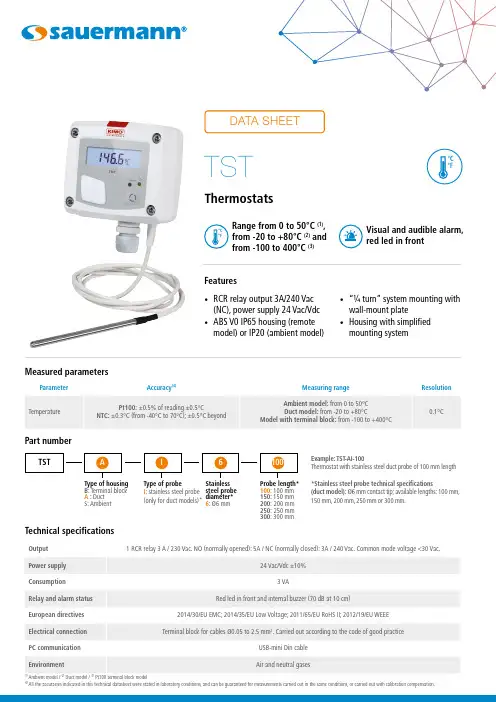
Technical specifications(4)All the accuracies indicated in this technical datasheet were stated in laboratory conditions, and can be guaranteed for measurements carried out in the same conditions, or carried out with calibration compensation.Features• RCR relay output 3A/240 Vac(NC), power supply 24 Vac/Vdc • ABS V0 IP65 housing (remote model) or IP20 (ambient model)• “¼ turn” system mounting withwall-mount plate• Housing with simplified mounting systemVisual and audible alarm, red led in frontRange from 0 to 50°C (1), from -20 to +80°C (2) and from -100 to 400°C (3)Part numberExample: TST -AI-100Thermostat with stainless steel duct probe of 100 mm length *Stainless steel probe technical specifications(duct model): Ø6 mm contact tip; available lengths: 100 mm, 150 mm, 200 mm, 250 mm or 300 mm.Type of housing B : Terminal block A : Duct S: AmbientType of probe I : stainless steel probe (only for duct models)*Probe length*100: 100 mm 150: 150 mm 200: 200 mm 250: 250 mm 300: 300 mmStainless steel probe diameter*6: Ø6 mmConnectionsElectrical connections as per NFC15-100 standardNO COM NC 1234567-+Power supply 24 VdcN L N L~~~~67Power supply 24 Vac Class IIThis connection must be performed by a qualified and trained technician. To make the connection, the transmitter must not be energized.NO: normally opened COM: common NC: normally closed1. Switch2. Terminal block (only on model with terminal block)3. LCC-S software connection4. Alarm led5. Button for settings6. Relay terminal block7. Power supply terminal block 8. Cable glandDimensions*Different probes available as option. Stainless steel probe technical specifications (duct model): Ø6 mm contact tip; available lengths: 100 mm, 150 mm, 200 mm, 250 mm or 300 mm.Connection of a Pt100 probe on terminal block:1 2 2’Measuring probeSymbols usedFor your safety and in order to avoid any damage of the device, please follow the procedure described in this document and read carefully the notes preceded by the following symbol:The following symbol will also be used in this document, please read carefully the information notes indicated after this symbol:2345678Inside the front housing Removable front face Fixed back housing1245678Ambient modelDuct model, stainless steel probe*Model with terminal block*Duct model*• Activate or deactivate an alarm- Press the button for 3 seconds, “CONF” is displayed then “NEG”, meaning that the relay is in negative security, it is excited during an alarm condition.- If needed, press quickly the button to switch the relay in positive security, the relay is de-energized during an alarm condition or a current breaking, “POS” is displayed.- Press 3 seconds the button, “Buzz” screen is displayed with “ON” or “OFF” blinking. Briefly press on the button to activate (“ON”) or deactivate (“OFF”) (according to the last saved configuration) the buzzer during an alarm condition.- Press the button for 3 seconds, “Alarm” screen is displayed with “On” or “Off” blinking (according to the last saved configuration).- Press quickly the button, the display changes from “On” (activated alarm) to “Off” (deactivated alarm).- Press the button for 3 seconds to confirm the setting. If the alarm is deactivated, the instrument displays the measurement; if the alarm is activated, the instrument displays the following setting.• Thresholds configurationThe button allows to activate or not an alarm (threshold), to set the action of the alarm (edge), to set the threshold(s) value, to set the time-delay and to acknowledge the alarm.• Set the threshold(s) valueThe first digit blinks, it corresponds to the positive (0) or negative (-) setting of the threshold value. Press briefly the button to select the sign for the threshold value. Press the button more than 3 seconds to validate.The second digit blinks, press briefly the button to scroll the numbers. Press the button more than 3 seconds to validate.Repeat the process until the last digit to configure the threshold value, validate the threshold and go to the following setting.If the monitoring edge has been selected, the transmitter displays the setting of the second threshold.Working principle:- By pressing the button more than 3 seconds, you can validate the setting and go to the next setting.- By pressing quickly the button, you can increment a value and scroll down the different option or values.- Press briefly the button to select the trespassing direction then press the button more than 3 seconds to validate this direction and set the thresholds.• Units settingTo set a unit of measurement, put the on-off switch 4 of the units as shown beside.Measurement (m) > Threshold (S) during the time-delay T1: alarm activation.Measurement (m) < Threshold (S) - Hysteresis (H) during the time-delay T2: alarm deactivation.Measurement (m) < Threshold (S) during the time-delay T1: alarm activation.Measurement (m) > Threshold (S) + Hysteresis (H) during time-delay T2: alarm deactivation.The alarm goes off when the measurement is outside the low and high thresholds.Rising edgeFalling edgeMonitoringModeMode Mode • Set the action of the alarm (rising edge or falling edge)The edge determines the action of the alarm according to the trespassing direction of the threshold(s).Rising edge (1 threshold): the alarm goes off when the measurement exceeds the threshold and stops when it is below the threshold.Falling edge (1 threshold): the alarm goes off when the measurement is below the threshold and stops when itexceeds the threshold.Monitoring (2 thresholds): the alarm goes off when the measurement is outside the defined low and high thresholds.Settings and use of the transmitterCAUTION: to configure the transmitter, it must not be energized. Then, you can make the settings required, with the DIP switches (as shown on the drawing below). When the transmitter is configured, you can power it up.• ConfigurationTo configure the transmitter, unscrew the 4 screws of the casing then open it. The switches allowing the different settings are accessible.Only the accessories supplied with the device must be used.• Set the hysteresisThe hysteresis only concerns the rising edge and the falling edge modes.In rising edge mode, the hysteresis allows to the transmitter to stay in alarm when the measurement is between the threshold and the threshold minus the hysteresis.Example: for a 70°C threshold and a 10°C hysteresis, the instrument will stay in alarm when the measurement will be between 70 and 60°C. In falling edge mode, the hysteresis allows to the transmitter to stay in alarm when the measurement is between the threshold and the threshold plus the hysteresis.Example: for a 70°C threshold and a 10°C hysteresis, the instrument will stay in alarm when the measurement will be between 70 and 80°C. The first digit blinks, set it by pressing the button briefly several times then press on the button more than 3 seconds to set the following digit.Once the hysteresis is set, press the button more than 3 seconds to validate and set the time-delays. • Set the time-delay 1 and the time-delay 2 (600 seconds maximum)- In rising edge mode, the time-delay 1 corresponds to the time lag before the alarm goes off when the threshold has been reached. The time-delay 2 corresponds to the time lag before the alarm stops when the measurement is lower than the threshold minus the hysteresis.Setting procedure: “Time 1” for the time-delay 1 is displayed then the time in second. The first digit blinks, press briefly on the button and scroll the figures. Press on the button more than 3 seconds to validate. Repeat the process until the last digit to set the time-delay 1 value (from 0 to 600 s) and validate. “Time 2” is displayed the time in second. Repeat the process to set the time-delay 2.- In falling edge mode, the time-delay 1 corresponds to the time lag before the alarm goes off when the threshold has been reached. The time-delay 2, corresponds to the time lag before the alarm stops when the measurement is lower than the threshold plus the hysteresis.The setting procedure is the same as the rising edge procedure.- In monitoring mode, the alarm of the transmitter goes off when the measurement is below the lower threshold and higher the high threshold. The time-delay 1 corresponds to the time lag before the alarm goes off when the measurement is below the lower threshold and higher the high threshold. The time-delay 2 corresponds to the time lag before the alarm stops when the measurement is between the lower and higher thresholds.The setting procedure is the same as the rising edge procedure. The setting of time delays is done, the measurement is displayed.F T _E N – T S T – 21/04/2020 – N o n -c o n t r a c t u a l d o c u m e n t – W e r e s e r v e t h e r i g h t t o m o d i f y t h e c h a r a c t e r i s t i c s o f o u r p r o d u c t s w i t h o u t p r i o r n o t i c e .Precautions for use: please always use the device in accordance with its intended use and within parametersdescribed in the technical features in order not to compromise the protection ensured by the device.No fixing plate is available for ambient model.4 fixing holes are inside the back housing.Configuration via LCC-S software (optional)The software allows to set the alarms, the thresholds, and the time-delay of the transmitter.• To access the configuration via software:- Set the DIP switches as shown beside.- Connect the cable of the LCC-S to the connection of the transmitter. Please refer to the user manual of the LCC-S software to make the configuration.• Please refer to the user manual of the LCC-S software tomake the configuration. The configuration of the parameters can be done either with the DIP switch or the software (combining both solutions is not possible). SWITCH OFF THE SENSOR before settings process.Active switch。

WS-104 数字显示温控器使用说明书一、功能特点:◆ 高级防水触摸按键面板。
◆ 外置宽电压开关电源。
◆具有:温度LED 显示、温度控制、自动和手动电热化霜控制、蒸发器风扇控制、压缩机延时启动保护,防误操作密码式设定参数、故障自诊断等功能。
◆ 小型一体化结构,可直接控制一匹以内压缩机。
◆ 适用各类风冷型冷柜及其它中低温制冷工程。
二、主要技术参数:◆ 电源电压:160~250VAC 。
◆ 控温范围:-40~45℃,精度:±1℃。
◆ 压缩机继电器触点:30A/240VAC 。
◆ 化霜继电器触点:10A/240VAC 。
◆ 蒸发器风扇继电器触点:10A/240VAC 。
◆ 冷库探头NTC :10K ;化霜探头NTC :10K 。
◆ 外观尺寸: 77×35×62(长×宽×深),单位:mm 。
◆ 安装开孔尺寸:71×29(长×宽),单位:mm 。
◆工作环境:温度:-10~60℃;相对湿度:20%~90%(无结露)。
三、指示灯:◆ 制冷指示灯:压缩机工作,制冷灯亮;压缩机延时启动,制冷灯闪烁;压缩机停止,制冷灯熄。
◆化霜指示灯:化霜过程中,化霜灯亮;化霜后滴水期间,化霜灯闪烁;退出化霜,化霜灯熄。
四、面板操作:◆设定控制温度:按键闪烁显示控制温度,按或键改变数值,按键存储控制温度并长鸣一声返回显示库温状态,如果10秒不按键,则不存储控制温度返回显示库温状态。
◆手动进入或退出化霜:按住键5秒长鸣一声,可进入手动化霜(在满足化霜探头温度小于化霜终止温度F3条件时)或退出化霜。
◆ 查看化霜探头温度:按住键5秒长鸣一声,闪烁显示化霜探头温度,按键或10秒不按键,返回显示库温状态。
◆设定参数:(注:进入设定参数的密码为“135”) 1.按住键5秒后,显示“000”,百位数闪烁,按或键输入百位数1;按键十位数闪烁,按或键输入十位数3;按键个位数闪烁,按或键输入个位数5;最后按键确认密码,如果密码正确,就显示参数代码“E1”,否则返回显示库温状态。
温湿度计操作规程
手持温湿度计操作规程
1、使用范围
1.1设备名称:手持温湿度计
1.2测量范围:湿度10%--95% ;温度-20℃-- +60℃,-4℉--+140℉
二、依据
《手持温湿度计使用说明书》
三、操作步骤
3.1测定湿度
1)打开仪器开关,将POWER开关置于“ON”的位置,
2)将FUNCT开关推至“%RH” 的位置,显示器(LCD)将立刻显示出湿度(%RH)的数值
3.2测定温度
1)打开仪器开关,将POWER开关置于“ON”的位置,
2)将FUNCT开关推至“℃”或“℉”的位置,显示器(LCD)将立刻显示出温度(℃或℉)的数值
3.3锁定数值
在测定湿度或温度时,将HOLD开关置于“ON”的位置,它将锁住目前所测得数值,直到将HOLD开关置于“OFF”的位置为止。
四、维护与保养
4.1若仪器的示数不清,说明电池电量不足,显示器(LCD)将显
示“BT”指示,应及时更换9V电池。
4.2每一季度进行一次仪器的维护与保养。
湖南工学院课程设计说明书课题:温度测量仪专业名称:电气工程及其自动化学生班级:电气本 1 1 0 1 班学生姓名:吕璇学生学号: 11401240102小组成员:徐露、蒋丹、吕璇指导教师:龙卓珉课程设计任务书一、课程设计的任务和目的学生通过理论设计和实物制作解决相应的实际问题,巩固和运用在《模拟电子技术》中所学的理论知识和实验技能,掌握常用模拟电路的一般设计方法,提高设计能力和实践动手能力,为以后从事电子电路设计、研发电子产品打下良好的基础。
二、课程设计的基本要求1、掌握电子电路分析和设计的基本方法。
包括:根据设计任务和指标初选电路;调查研究和设计计算确定电路方案;选择元件、安装电路、调试改进;分析实验结果、写出设计总结报告。
2、培养一定的自学能力、独立分析问题的能力和解决问题的能力。
包括:学会自己分析解决问题的方;对设计中遇到的问题,能通过独立思考、查询工具书和参考文献来寻找解决方案,掌握电路测试的一般规律;能通过观察、判断、实验、再判断的基本方法解决实验中出现的一般故障;能对实验结果独立地进行分析,进而做出恰当的评价。
3、掌握普通电子电路的生产流程及安装、布线、焊接等基本技能。
4、巩固常用电子仪器的正确使用方法,掌握常用电子器件的测试技能。
5、通过严格的科学训练和设计实践,逐步树立严肃认真、一丝不苟、实事求是的科学作风,并逐步建立正确的生产观、经济观和全局观。
目录第一章绪论 (5)1.1课题研究背景和意义 (5)1.2 本人主要工作 (5)第二章方案设计 (7)2.1 基本原理 (7)2.2温度传感器的选择 (7)2.3 AD590温度传感器的简介 (7)第三章电路设计 (9)3. 1 单元电路设计 (9)3.1.1温度—电压变换电路 (9)3.1.2K—℃变换器 (9)3.1.3 2.732V电压产生电路 (9)3.1.4 放大器 (10)3.1.5 比较器 (11)3.1.6 驱动电路 (11)3.2 整体电路图设计 (13)第四章仿真与制作 (14)4.1 电路仿真 (14)4.2 PCB电路板制作 (17)4.2.1 protell使用简要说明 (17)4.2.2 绘制SCH原理图 (17)4.2.3 做SCH零件库元件 (20)4.2.4 做PCB零件封装 (20)4.3 温度测量仪的调试 (22)4.3.1 调试要点和注意事项 (22)4.3.2实物的调试 (22)第五章结束语 (23)第六章参考文献 (24)附录 A 元件清单 (25)附录 B 实物图 (26)第一章绪论1.1 课题研究背景和意义温度是表示物体冷热程度的物理量,微观上来讲是物体分子热运动的剧烈程度。
显示屏选择键查看最大值选择键查看最小值红外传感器红外测量按钮电池闸本品已获《中华人民共和国制造计量器具许可证》粤制:00000743testo 830-S1红外测温仪1. 一般说明在使用本产品前,请仔细通读本操作手册并熟悉产品的操作。
请妥善保管本手册,以便在需要时您可以参考。
2. 产品描述3. 安全信息红外测量:当测量带电部件时,请保持所需的安全距离避免电气危险:产品安全/保修条款声明:按照产品的预定用途,在规定的参数范围内正确操作本仪器。
不要太过用力!不要暴露至电磁辐射(例如,微波、感应加热系统)、静电、高温或温度剧烈变动等情况下。
不要与溶剂(如丙酮)放在一起仅在文档中明确描述了用于维护目的时,才能打开仪器激光辐射!不要直视激光束保证正确处置:请把损坏的充电电池和废电池放到指定的收集点请在仪器报废时直接将仪器寄送给我们,我们保证以环保的方式处置它们4. 预定用途testo 830-S1是用于表面温度的非接触测量的红外测温仪不适用于医疗领域的诊断测量!5. 技术数据红外测量范围红外测量分辨力红外测量最大允许误差(23°C 时) ± 1数位发射率红外测量速率光学分辨率操作温度储存温度电源电池使用时间外壳材质尺寸(长×高×宽)CE 标准保修激光激光瞄准功率波长等级标准(-30 ~ +350)°C 0.1°C±1.5°C 或1.5%读数(+0.1 ~ +350)°C 1);±2°C 或2% 读数(-30 ~ 0)°C 1)0.1 ~ 1.0可调节0.5s 10:12)(-20 ~ +50)°C (-40 ~ +70)°C 9V 块状电池20 h ABS190 x 75 x 38 mm / 7.5 x 3.0 x 1.5 in 2004/108/EEC 1年1 x 激光< 1 mW 645 ~ 660 nm 2DIN NE 60825-1:2001-111) 取数值大者2) +传感器的开口直径(16mm / 0.6 in)6. 初始操作放入电池:参见“9.1 更换电池”7. 操作7.1 开/关机开启仪器:按下测量按钮。
Conquer any AC/Refrigeration complication - effortlessly!testo Smart Digital Manifolds, Smart Probes, and thenew testo 560i Digital Refrigerant Scale and Intelligent ValveSMART HVAC/RInstruments from Testo2Refrigeration technology – made easy. Your work will be more efficient & convenient than ever before.Put an end to complexity and unnecessary workload: To make your daily work faster, smarter, and even more professional, our portfolio has taken measurement calculations to a whole new level.App-controlled measurement technology puts an end to time-consuming calculations, tangled cables, and piles of paperwork. From now on, Testo’s whole team of professional helpers will be at your side:• The testo 557s/550s/550i Digital Manifolds are made better with improved smart interactionwith the testo Smart App and the new testo 560i Digital Refrigerant Scale and Intelligent Valve.• The new testo 560i Digital Refrigerant Scale and Intelligent Valve saves time and nerves by automaticallycharging refrigeration systems according to target values.• The free testo Smart App brings all instruments together wirelessly and offers easy operation,measurement, and documentation.•Best of all: Our Smart HVAC/Refrigeration instruments automatically connect to each other in seconds!NEW!More about refrigeration measurement technology from Testo at Your Smart team for HVAC/R.Our measuring instruments make it possible.Thanks to our Smart measuring instruments, ease of operation goes hand in hand with maximum precision, because all Testo HVAC/Refrigeration instruments can be connected automatically using the T esto Smart App. Our innovative products cover all measurement tasks related to refrigeration technology, making everything simple and smart for you. Here is how it works:Refrigeration system adjustments made easy:Through wireless interaction of our testo 557s, 550s, and550i Smart Digital Manifolds and testo Smart Probesfor measuring pressure, temperature, and humidity with ourintelligent testo Smart App.Charging refrigeration systems – more convenientlythan ever before, thanks to wireless interaction withthe new testo 560i Digital Refrigerant Scale andIntelligent Valve,the testo Smart App,and testoSmart Digital Manifolds for automatic chargingaccording to refrigerant weight/superheat/subcooling, andeven target superheat.Evacuating refrigeration systems – super easy throughwireless interaction of the testo 552i Vacuum SmartProbe and testo Smart App for cable-free and hose-freevacuum measurement.In summary: everything becomes effortless – thanks to the combination of our Smart measuring instruments’ interaction with each other, and connectivity to the testo Smart App.More about refrigeration measurement technology from Testo at World innovation from Testo is here:The new testo 560i Digital Refrigerant Scale and Intelligent Valve. It makes charging refrigeration systems, ductless mini splits, and heat pumps revolutionarily simple. The new Smart digital scale and intelligent valve enable automatic charging according to the target superheat – thanks to patented technology. This is how they workas a team with our Smart Digital Manifolds, AC/ Refrigeration Smart Probes, and the testo Smart App.testo 560i – this is how progress works: The connection of the instruments via Bluetooth is fully automatic and completely effortless... As is the charging process: You can choose from five automatic programs: Manual/Recovery, Automatic by Weight, Super Heat, Sub Cooling, or Target Super Heat. Simply select the charging program in the Testo Smart Digital Manifold or testo Smart App, enter the target value and the Digital Refrigerant Scale + Intelligent Valve do the rest for you.Fully automatic charging - fully simple.The new testo 560 Digital Refrigerant Scale and Intelligent Valve.NEW!•Fully automatic refrigerant charging with scaleand intelligent valve.•The scale and valve are compatible via Bluetoothwith the testo Smart App, testo Smart DigitalManifolds testo 557s, 550s, 550i, Digital Manifoldswith Bluetooth testo 557/550, and testo SmartProbes 115i, 549i, 605i.•The new testo 560i Automatic Filling System isavailable in a complete set with valve, batteriesand shoulder bag.The fully automatic charging functionality will be available viatesto Smart App update at the end of April 2022.More information about testo 560i at 45testo 560iMore incredible features•All measured values for the charging process available at a glance with storage of measurement data in the testo Smart App. • High measuring accuracy with a maximum load of 220 lbs. for all common refrigerant containers. • Super handy: Compact housing, low weight, convenient carrying handle and sturdy shoulder bag. •3D corners for accurate positioning and textured rubber surface for stable hold of the refrigerant container.•Power in every respect: Long battery life of up to 70 hrs. (4 x AA, included)Bluetooth range up to 100 feet.More information about testo 560i at 6Simply first class:our three Smart Digital Manifolds.7Our testo 557s, 550s, and 550i Smart Digital Manifolds make your measurements on refrigeration, air conditioning, and heat pumps fast, easy, and convenient like never before. The large display shows all measurement data at a glance and simplifies the analysis of all results. Guided measurement menus take you step by step through the measurement and allow you to determine high and low pressure, condensing and evaporating temperature, as well as superheat/subcooling.The testo Smart Probes for temperature, pressure,and humidity can be connected wirelessly and fully automatically to the instrument , and together with the testo Smart App, provide even more flexibility in the application.Another advantage: Our Smart Manifolds and Smart App always select the right refrigerant ready for you. Everything for maximum precision: From the first to last job.More information about Testo‘s manifolds at Type text here8May we introduce: testo 115i wireless clamp thermometer. The ideal temperature measuring instrument for installation, service and troubleshooting on refrigeration and air conditioning systems.Get a precise grip on temperature: testo 115i.testo 552i – Vacuum measurement has never been so easy.The testo Smart App-controlled testo 552i Vacuum Probe offers you many advantages:It expands the testo Smart Probes portfolio with the option of measuring vacuum wirelessly and fast, with just one service port.Wireless, compact & App-controlled measurements made effortless – with testo Smart Probes.• Fast identification of temperature changes by graphic progression display.•Measurement data are transmitted wirelessly from the testo 115i to the testo Smart App and can be viewed conveniently on your smartphone or tablet.• Enables measurement of flow and return temperatures.• Measurement data analyzed and sent via testo Smart App.• Problem-free use at measuring points that are spaced far apart thanks to a Bluetooth ® range up to 328 ft.•Automatic connection to testo Smart manifolds: Values of the 115i are displayed directly on screen. Temperature changes areimmediately evident.More advantages at a glance:• Identify vacuum quickly and easily through graphical representation in the testo Smart App or on the testo Smart Digital Manifold’s display.• Measure vacuum without cables or hoses - the testo 552i connects to the testo Smart App and testo Smart Digital Manifolds.• Compact, reliable and robust with IP 54 protection class housing. •Easy installation on any service port with integrated 45° angle connection.More information about testo 552i at More information about testo 115i at 9Downloadnow free ofchargeFor Androidand IOS•Intuitive user interface: all information at a click•Graphic display of up to 4 measurement values atthe same time•Manage customer profiles and measuringpoints: testo Smart App, testo Digital Manifolds andsoftware synchronize via Wi-FiTurn your smartphone into your control center: The testo Smart Appconveniently connects with, and controls testo Smart instrumentsfor all refrigeration and air conditioning applications. This wayyou always have an overview of your data, exactly where you need it.With the testo Smart App, evaluating reports has never been faster.The testo Smart App helps you to avoid measurement errors,as integrated measurement programs guide you step by stepthrough the configuration and the measurement. You can also createcustomer data and measuring locations in no time at all.Your workflow: effortless.Your job has never been so smart.Easy management of measurement & customer data. testo DataControl makes it possible.•Intuitive measurement menus•Easy documentation•Send measurement reports as PDF or Excel•Use your tablet/smartphone as a second screen•For all refrigeration and air conditioning applications•Wireless connection to all measuring instruments forrefrigeration and air conditioning applicationsGet your data where you need it! With our testo DataControl software, measurement results and customer profiles can be managed easily and quickly on a PC – and the documentation is created nearly instantaneously.More information about testo Smart App at 10Six ready-to-go kits. Order manifolds now.* testo 550i also available as an individual instrument, incl. batteries (3 x AAA), calibration protocol and instruction manual, order no. 0564 2550 01More information about testo Smart Digital Manifolds at 11Order no. 0564 1001Magnetic strap for manifoldstesto 557s/550s/550itesto 552iWireless vacuum probetesto 316-3Leak detector for refrigerantstesto Smart ProbesAC/Refrigeration Test and Load kit2x testo 115i / 2x testo 549i2x testo 605i / Smart Case Everything that makes life easy...Testo instruments: Scale to Smart Probes.testo 560iDigital Refrigerant Scale andIntelligent Valve with Bagtesto 560iDigital Refrigerant Scale with Bagtesto 115iWireless temperature probetesto 549iWireless high pressure probetesto 605iWireless thermohygrometerMore information about testo Smart Probes at Every charging: effortless.NEW!More information about testo 560iat Our new Digital Refrigerant Scale and Intelligent Valve offers you a real sensation: superheat, subcooling or weight. Simple, convenient and time-saving.。
1 目的规范Testo 106食品温度计操作程序,正确使用仪器,保证检测工作顺利进行,检测数据正确。
2 适用范围适用于食品领域液体物质、糊状物质和半固体物质的中心温度测量。
3 职责3.1 操作人员按照本规程操作仪器,对仪器进行日常维护,做使用登记。
3.2 保管人员负责监督仪器操作是否符合规程,对仪器进行定期维护、保养。
3.3 科所负责人负责仪器综合管理。
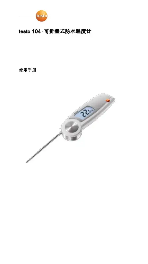
4 工作程序4.1 仪器配件4.1.1 Testo 106食品温度计(1只)4.1.2 CR2032型电池(2节)4.2 仪器操作步骤4.2.1 初始操作拔下保护套,打开电池盒盖,装入2节CR2032型电池(注意极性),关闭电池盒盖。
4.2.2 开机打开ON 键。
HOLD4.2.3 仪器设置4.2.3.1 持续按ON 键,打开配置模式;HOLD4.2.3.2 选择温度测量单位(℃或℉):▲。
选择确认:ON 键;HOLD4.2.3.3 打开AUTO OFF(On)或关闭AUTO OFF(OFF):▲,选择确认ON 键;(如果自动关机功能AUTO OFF开启)HOLD设置读数稳定(变化小于0.2℃)并锁定下来需要持续的时间(5,10,15或20 S):▲,选择确认:ON 键;HOLD4.2.3.4 报警声音:打开(O n)或报警声音关闭(OFF):▲,选择确认:ON 键;HOLD4.2.3.5 报警灯LED:打开(On)或报警灯LED关闭(OFF):▲,选择确认:ON 键;HOLD4.2.3.6 AUTO OFF打开(On)或AUTO OFF关闭(OFF):▲,选择确认:ON 键;HOLD4.2.3.7 设置完成,仪器返回到测量视图。
4.2.4 测量4.2.4.1 探头插入被测物体中(为确保测量结果的准确性,请注意浸入/插入深度:>15mm);4.2.4.2 显示当前读数,按动ON 键,手动锁定读数,HOLD标识亮起;HOLD4.2.4.3 所示读数即为所测食品的中心温度,记录读数。
testo 400参考级多功能测量仪testo 950参考级温度测量仪testo 650参考级湿度测量仪操作手册V2.02目录页码简介 (3)仪器的初始操作 (4)仪器介绍 (6)功能区 (8)菜单概览/配置 (9)功能键分配方案 (10)打印机初始化操作一体化打印机0554.0570 (12)德图打印机0554.0545 (14)仪器出错信息 (15)仪器复位数据 (16)数据管理 (17)操作条码 (18)测量任务示例温度测量 (19)湿度测量 (24)Aw值测量 (28)自动保存 (30)风速测量 (37)WBGT测量 (44)NET测量 (45)压力测量 (46)转速测量 (46)电流/电压测量 (47)大气压测量 (48)泄露检测探头 (49)CO/CO2测量 (50)电源 (51)软盘升级 (52)技术资料 (53)仪器符合89/336/EWG标准翻印版权Testo GmbH&Co.testo 400产品以内的软件和软件结构均受全球版权条例的保障!亲爱的用户:购买德图测量仪器一定是您正确的选择,每年都有数以千计的用户购买我们的高质量产品。
这种情况源于以下原因:1)性能-价格比。
价格合理而且性能可靠。
2)根据不同的仪器,我们的保修期可延长至3年。
3)基于40多年的专业仪器制造经验,我们能够针对您的测量任务提出理想的解决方案。
4)ISO 9001质量认证保证了我们产品的质量。
5)我们的产品根据EU的要求贴有CE标志。
6)所有相关参数都附有标定证书并在当地提供标定服务,举办各种培训会以及提供技术咨询。
7)完善的售后服务。
您所购买的仪器是一种高度灵活的、可升级的测量系统。
他们的测量范围及应用软件可随不同的安装方式而变化。
打开仪器后,您立刻就会得到有关仪器类型、编号以及本仪器中使用的软件版本等信息。
其他相关信息如售后服务等资料可通过打印机得到(见16页)。
本手册将给出testo 400、testo 650 和testo 950最大的工作范围。
1 目的规范Testo 106食品温度计操作程序,正确使用仪器,保证检测工作顺利进行,检测数据正确。
2 适用范围适用于食品领域液体物质、糊状物质和半固体物质的中心温度测量。
3 职责3.1 操作人员按照本规程操作仪器,对仪器进行日常维护,做使用登记。
3.2 保管人员负责监督仪器操作是否符合规程,对仪器进行定期维护、保养。
3.3 科所负责人负责仪器综合管理。
4 工作程序4.1 仪器配件4.1.1 Testo 106食品温度计(1只)4.1.2 CR2032型电池(2节)4.2 仪器操作步骤4.2.1 初始操作拔下保护套,打开电池盒盖,装入2节CR2032型电池(注意极性),关闭电池盒盖。
4.2.2 开机打开ON 键。
HOLD4.2.3 仪器设置4.2.3.1 持续按ON 键,打开配置模式;HOLD4.2.3.2 选择温度测量单位(℃或℉):▲。
选择确认:ON 键;HOLD4.2.3.3 打开AUTO OFF(On)或关闭AUTO OFF(OFF):▲,选择确认ON 键;(如果自动关机功能AUTO OFF开启)HOLD设置读数稳定(变化小于0.2℃)并锁定下来需要持续的时间(5,10,15或20 S):▲,选择确认:ON 键;HOLD4.2.3.4 报警声音:打开(O n)或报警声音关闭(OFF):▲,选择确认:ON 键;HOLD4.2.3.5 报警灯LED:打开(On)或报警灯LED关闭(OFF):▲,选择确认:ON 键;HOLD4.2.3.6 AUTO OFF打开(On)或AUTO OFF关闭(OFF):▲,选择确认:ON 键;HOLD4.2.3.7 设置完成,仪器返回到测量视图。
4.2.4 测量4.2.4.1 探头插入被测物体中(为确保测量结果的准确性,请注意浸入/插入深度:>15mm);4.2.4.2 显示当前读数,按动ON 键,手动锁定读数,HOLD标识亮起;HOLD4.2.4.3 所示读数即为所测食品的中心温度,记录读数。