QK1334管螺纹车床电气说明书
- 格式:pdf
- 大小:425.26 KB
- 文档页数:30
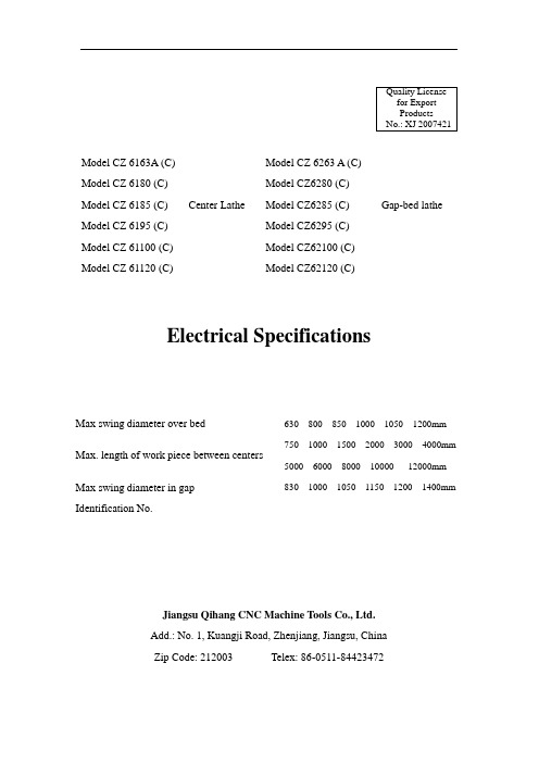
Model CZ 6163A (C) Model CZ 6263 A (C)Model CZ 6180 (C) Model CZ6280 (C)Model CZ 6185 (C) Center Lathe Model CZ6285 (C) Gap-bed lathe Model CZ 6195 (C) Model CZ6295 (C)Model CZ 61100 (C) Model CZ62100 (C)Model CZ 61120 (C) Model CZ62120 (C)Electrical SpecificationsMax swing diameter over bed 630 800 850 1000 1050 1200mmMax. length of work piece between centers 750 1000 1500 2000 3000 4000mm 5000 6000 8000 10000 12000mmMax swing diameter in gapIdentification No.830 1000 1050 1150 1200 1400mmJiangsu Qihang CNC Machine Tools Co., Ltd.Add.: No. 1, Kuangji Road, Zhenjiang, Jiangsu, ChinaZip Code: 212003 Telex: 86-0511-********ContentI. Overview ............................................................................................................... - 1 -1. Power supply .................................................................................................. - 1 -2. V oltage of control circuit ................................................................................ - 1 -3. Motor of machine tool ................................................................................... - 1 -4. Door-opening power outage .......................................................................... - 1 -5. Grounding protection ..................................................................................... - 1 - II. Electric control and operation .............................................................................. - 2 -1. Preparations before start-up ........................................................................... - 2 -2. Start-up ........................................................................................................... - 2 -3. Electrically controlled operation .................................................................... - 2 -4. Shutdown ....................................................................................................... - 3 - III. Attached drawings and list of electrical devices ................................................. - 3 -1. Attached drawings .......................................................................................... - 3 -2. List of electrical devices ................................................................................ - 3 -I. Overview1. Power supplyThe following power supply voltage and frequency for the machine tool can beprovided based on customer needs:Lead-in wire of power supply:L1L2 three phase power supply sectional area 6mm2L3PE ground wire2. Voltage of control circuitV oltage of control circuit is ~ 24V or ~ 110V, signal lamp circuit ~ 6V and that of working lamp is ~ 24V.Power line is black, AC control line red, working ground wire white and protective ground wire yellow green.3. Motor of machine toolA machine tool has three motors:M1--- Spindle motorM2--- Longitudinal rapid-travel motorM3---Cooling motorNote: Motors of corresponding frequency 50 Hz or 60 Hz are provided in accordance with user network power supply in the purchase contract.4. Door-opening power outageLock of DZL5 electric control cabinet is adopted for the door of electric box, which is interlocked with power switch QF1 to realize the protection of power outage before door opening.5. Grounding protectionUser shall provided favorable grounding network and machine tool and electric box shall be properly grounded.II. Electric control and operation1. Preparations before start-upThe door of electric box is firstly opened with the key prior to the initial start-up of the machine tool to check whether all the automatic switches are connected and whether all connecting terminals and ground terminals are reliably connected. The door is closed after the checking is completed.Properly close the door of belt housing and the chuck shield.2. Start-upTurn the door lock handle upwards and power switch QF1 of the machine tool is at the connection position, indicating the machine tool is energized. Power indicators HL1 and HL2 are on and the machine tool can enter normal work. Power supply phase sequence shall be checked for the first electrification of machine tool. Press the start-up button SB2 (green) on the push button station at the head of the machine tool and the main motor starts running. Operate the handle of start-up rod to the position of forward turning. If the spindle turns forward, it demonstrates a correct phase sequence, otherwise any two phase lines need to be exchanged in the power circuit. 3. Electrically controlled operationThe main motor has two forms of start-up and running. If it is started directly, press button SB2 (green) and KM1 is powered and the main motor starts running. If the main motor adopts Y-Δ start-up, press SB2 (green) and KM1, KM2 and KT are electrified. When the main motor uses Y start-up, KM is de-energized after 3s delay of KT and KM2 is energized and the main motor transfers to △running. Thereafter, operating the handle of start-up rod can realize spindle forward turning, reverse turning and stop.Rotate SA, the handle points to the right and the water pump is opened and it is closed when the handle points to the left. Press button SB3 (red), both main motor and cooling pump motor stop operation. Pressing and connecting switch SQ2 andholding slide carriage button SB4 or SB5 can make the rapid-travel motor turn forward or reversely and realize gap rapid travel to the left or the right.4. ShutdownIf the machine tool is not used, the master power switch QF1 shall be disconnected for personal and equipment safety.III. Attached drawings and list of electrical devices1. Attached drawingsFig. 7 (1): Electrical schematic diagram 1 Fig. 7 (2): Electrical schematic diagram 1 Fig. 7 (3): Electrical schematic diagram 1 Fig. 8 (1): Electrical wiring diagram of machine tool 1 Fig. 8 (2): Electrical wiring diagram of machine tool 1 Fig. 9 (1): Location map of electrical devices on the distribution board 1 Fig. 9 (2): Location map of electrical devices on the distribution board 1 2. List of electrical devices(1) Electrical list for directly started main motor(2) Electrical list for Y- △ started main motor- 1 -- 2 -。
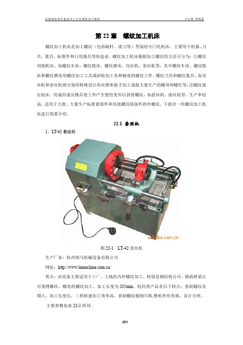
xx煤矿管螺纹车床技术要求根据xx集团规[2016]11号文件《关于下达xxx2016年专项资金计划的通知》,结合矿井实际情况,①因我矿现在井下注浆使用孔口管数量增加。
②现井下常用孔口管φ146mm,现在xx队车床最大能车φ130mm,为了能车φ146mm孔口管,机修队使用自制卡盘,非常不安全,且速度非常慢。
③车床出厂日期1980年,已使用35年,设备老化。
故xx煤矿需购置一台管螺纹车床,其技术要求如下:一、使用条件1、满足切削金属钢管需要。
2、能固定安装在车间内使用。
二、供货范围及主要部件:三、设备技术参数1、最大车削长度(最大加工长度) 1000mm2、最大加工管子外径 60-219mm3、主轴通孔直径 240 mm4、主轴转速范围 8-306 r/min5、上刀架最大行程 200mm6、下刀架最大横向行程 300 mm7、刀杆截面尺寸(四方刀架刀杆截面) 30*30mm8、床尾套筒行程 250mm9、加工公制螺纹范围及种数 1-15(22种) mm10、加工模数螺纹范围及种数 0.5-7.5(21种)mm11、加工径节螺纹范围及种数 2-28(20种) DP12、锥度尺最大加工长度 600mm13、主电机功率 18.5kW14、纵横进给量范围及种数 0.94-1.44(32种) mm四、技术要求:1.床身经过表面淬火、磨削加工。
2.床头箱齿轮经过齿部淬火,精密磨齿加工;高速齿轮精度要达到5级;床头箱主轴刚性好。
3.机床的溜板箱设有快速移动装置、过载安全装置。
4.公制机床。
6.主电机功率为18.5kW.五、建议厂(商)家:。

机床电气手册2007-1-15目录1、机床电气操作说明2、机床电气元件目录3、机床电气原理图及控制柜布局图4、软件程序机床电气操作说明1、机床概述______(型号)枪钻主要采用有独立PLC功能的时光伺服控制器作为进给系统。
利用伺服控制器的简易PLC功能以及通讯功能研发的一款以触摸屏为上位机,伺服驱动器为伺服单元的新型专用机床。
2、操作说明欢迎画面点击进入点击输入参数参数说明:快进速率:自动时快速到工进位以及返回零点的速率。
工进速率:自动时的工进速率。
手动速率:手动操作时的速率。
快进行程:自动时的工进起始位位置。
总行程:自动时的工进到位位置。
参数说明:前软限位:前软限位到原点的距离。
后软限位:后软限位到原点的距离。
启动延时:自动时启动信号的确认时间。
进给到位延时:自动时工进到位后的延时。
浮漂检测去抖:浮漂信号的确认时间。
限位设置示意图后软限位前软限位原点数值输入窗口清除返回删除确认操作界面点击选择手动/自动自动状态下:触摸屏:闪烁,对刀操作与手动界面无效。
按钮站:按住启动按钮,等确认时间后,机床执行自动动作,在动作中可按暂停按钮暂停动作。
手动状态下:闪烁,可以进行对刀操作,可以进入手动界面。
复位与参数设置按钮任何情况下都有效。
手动界面手动界面的操作规程:进给的允许条件:导套进冷却启动主轴启动进导套退的允许条件:主轴关闭冷却关闭导套退滤纸与退按钮无操作限制。
机床电气元件目录软件程序1、伺服控制器程序;************************************************* ; Copyright (c) 2006,时光科技有限公司技术支持部; All rights reserved.;; 文件名称:枪钻机床控制.S; 文件标识:IMS-GCT40P7S; 摘要:; 当前版本:1.0; 作者:杨征; 完成日期:2006年1月5日;************************************************* ;备注:;***********输入口**************;A0D0- 自动手动切换(1-手动;0-自动);A0D1- 手动进;A0D2- 手动退;A0D3- 手动导套进;A0D4- 手动导套退;A0D5- 手动主轴;A0D6- 手动冷却;A0D7- 手动滤纸;A0D8- 手动调整切换(0-手动;1-调整);A0D9- 复位;C4D0- 主轴检测;C4D1- 冷却电机检测;C4D2- 导套到位检测;C4D3- 导套原位检测;C4D4- 浮漂检测;C4D5- 压力检测;C5D0- 启动;C5D1- 前限位;C5D2- 后限位;C5D3- 原位;C5D7- 暂停;***********输出口************;ALM-报警口(0-伺服正常;1-伺服异常);C0D0-主轴启动指示;C0D1-冷却启动指示;C0D2-运行指示;C0D3-滤纸堵塞指示;C0D4-滤纸启动指示;C0D7-磁分离器;C1D0-主轴;C1D1-冷却泵;C1D2-导套进;C1D3-导套退;C1D4-滤纸;***********用户参数*************;NO.00($FE50)- 快移速率(mm/min);NO.01($FE52)- 工进速率(mm/min);NO.02($FE54)- 快移行程(0.01mm);NO.03($FE56)- 总行程(0.01mm);NO.04($FE58)- 手动速率(mm/min);NO.05($FE5A)- 前软限位(0.01mm);NO.06($FE5C)- 后软限位(0.01mm);NO.07($FE5E)- 进给到位延时(0.1sec);NO.08($FE60)- 启动按钮延时(0.1sec);NO.09($FE62)- 去抖延时(0.1sec);NO.10($FE64)- PSG;*****************程序*******************CALL $460PLSI=0A0=0A9=0 ;回零标志字POKE $FF04 0POKE $F01C 40ONTIM2 X00K00 JNE F00 A0 AND 512JEQ Z00 A0 AND 1JNE S00 A0 AND 1JMP K00;****************手动*****************S00 JSR H00JSR C00S02 JNE F00 A0 AND 512 ;复位?JEQ Z00 A0 AND 1 ;自动?JNE T00 A0 AND 256 ;进入调整状态?DPEEK A2 $FE58 ;读取手动速度并计算A2=A2*2/3S07 A1=A0 AND 6JEQ S10 A1-2JEQ S30 A1-4JMP S90S10 JNE S90 C5 AND 2 ;碰到前限位?JEQ S90 A7-1 ;碰到前软限位?S25 JSR D00 ;电机上电C0=C0 OR 4HZP=-A2JMP S02S30 JNE S90 C5 AND 4 ;碰到后限位?JEQ S90 A8-1 ;碰到后软限位?S45 JSR D00 ;电机上电C0=C0 OR 4HZP=A2JMP S02S90 JSR C00JMP S02;*****************调整*******************T00 JSR H00JSR C00T05 JEQ S00 A0 AND 256JEQ Z00 A0 AND 1 ;自动?DPEEK A2 $FE58 ;读取手动速度并计算A2=A2*2/3A1=A0 AND 6 ;手动进给JEQ T20 A1JEQ T10 A1-2JEQ T15 A1-4JEQ T20 A1-6T10 JNE S90 C5 AND 2 ;碰到前限位?JEQ S90 A7-1 ;碰到前软限位?JEQ T30 C4 AND 1JEQ T30 C4 AND 2JEQ T30 C4 AND 4JEQ T30 C4 AND 32JSR D00C0=C0 OR 4HZP=-A2JMP T30T15 JNE S90 C5 AND 4 ;碰到后限位?JEQ S90 A8-1 ;碰到后软限位?JSR D00C0=C0 OR 4HZP=A2JMP T30T20 JSR C00C0=C0 AND 251T30 JNE T35 A0 AND 32 ;手动主轴C1=C1 AND 254JNE T40 C4 AND 1C0=C0 AND 254JMP T40T35 JEQ T40 C4 AND 2JEQ T40 C4 AND 32C1=C1 OR 1JEQ T40 C4 AND 1C0=C0 OR 1T40 JNE T45 A0 AND 64 ;手动冷却C1=C1 AND 253JNE T50 C4 AND 2C0=C0 AND 253C0=C0 AND 127JMP T50T45 JEQ T50 C4 AND 4C1=C1 OR 2JEQ T50 C4 AND 2C0=C0 OR 2C0=C0 OR 128T50 JNE T55 A0 AND 128 ;手动滤纸C1=C1 AND 239C0=C0 AND 239JMP T60T55 C1=C1 OR 16C0=C0 OR 16T60 A1=A0 AND 24 ;手动导套JEQ T05 A1JEQ T70 A1-8JEQ T80 A1-16JEQ T05 A1-24T70 C1=C1 AND 247C1=C1 OR 4JMP T05T80 JNE T05 C4 AND 1JNE T05 C4 AND 2C1=C1 AND 251C1=C1 OR 8JMP T05;*****************自动*******************Z00 JEQ K00 A9JNE Z05 C5 AND 1JMP K00Z05 DPEEK A6 $FE60A6=A6*43TIC1=A6Z10 JEQ K00 C5 AND 1JNE Z10 TIC1JNE S00 A0 AND 1 ;手动?JNE F00 A0 AND 512 ;复位?JNE M00 C5 AND 128 ;暂停?JNE S90 C5 AND 2 ;碰到前限位?JEQ S90 A7-1 ;碰到前软限位?Z20 JSR D00JSR J00Z25 DPEEK B0 $FE50DPEEK B1 $FE52DPEEK B2 $FE54DPEEK B3 $FE56B0=B0*2/3B1=B1*2/3AA=B2*20AC=B3*20AA=2000-AAAC=-ACPOS=ACA3=0MAXHZ=B0DPOKE $F0DC B0JNE S00 A0 AND 1 ;手动?JNE F00 A0 AND 512 ;复位?JNE M00 C5 AND 128 ;暂停?JNE S90 C5 AND 2 ;碰到前限位?JEQ S90 A7-1 ;碰到前软限位?JEQ Z80 C4 AND 1JEQ Z80 C4 AND 2JEQ Z80 C4 AND 4JEQ Z80 C4 AND 32JSR D00JSR J00C0=C0 OR 4DPEEK PSG $FE64Z30 JMI Z40 PLS-AAJNE S00 A0 AND 1 ;手动?JNE F00 A0 AND 512 ;复位?JNE M00 C5 AND 128 ;暂停?JNE S90 C5 AND 2 ;碰到前限位?JEQ S90 A7-1 ;碰到前软限位?JEQ Z80 C4 AND 1JEQ Z80 C4 AND 2JEQ Z80 C4 AND 4JEQ Z80 C4 AND 32JNE Z30 PSGZ40 MAXHZ=B1DPOKE $F0DC B1Z50 JNE S00 A0 AND 1 ;手动?JNE F00 A0 AND 512 ;复位?JNE M00 C5 AND 128 ;暂停?JNE S90 C5 AND 2 ;碰到前限位?JEQ S90 A7-1 ;碰到前软限位?JEQ Z80 C4 AND 1JEQ Z80 C4 AND 2JEQ Z80 C4 AND 4JEQ Z80 C4 AND 32JNE Z50 PSGC0=C0 AND 251DPEEK A6 $FE5EA6=A6*43TIC1=A6Z60 JNE Z60 TIC1JSR H00Z65 POS=0A3=1MAXHZ=B0DPOKE $F0DC B0JNE S00 A0 AND 1 ;手动?JNE F00 A0 AND 512 ;复位?JNE M00 C5 AND 128 ;暂停?JNE S90 C5 AND 4 ;碰到后限位?JEQ S90 A8-1 ;碰到后软限位?C0=C0 OR 4DPEEK PSG $FE64Z70 JNE S00 A0 AND 1 ;手动?JNE F00 A0 AND 512 ;复位?JNE M00 C5 AND 128 ;暂停?JNE S90 C5 AND 4 ;碰到后限位?JEQ S90 A8-1 ;碰到后软限位?JNE Z70 PSGC1=C1 AND 251C1=C1 OR 8JSR C00JMP K00Z80 JSR C00JMP Z25;*****************暂停*******************M00 PSG=0HZP=0JNE M00 HZSC0=C0 AND 251JEQ M00 C5 AND 1JEQ Z25 A3JEQ Z65 A3-1JMP M00;*****************复位*******************F00 JNE F60 A9JSR C00DPEEK B0 $FE50B0=B0*2/3JSR D00JSR H00C0=C0 OR 4HZP=B0F10 JNE F20 C5 AND 4JEQ F10 C5 AND 8JMP F30F20 HZP=-B0F25 JEQ F25 C5 AND 8F30 HZP=-100F40 JNE F40 C5 AND 8POKE $FF00 1F50 PEEK B9 $FF00JNE F50 B9F60 HZP=0PSG=0JNE F60 HZSF65 JSR D00JSR H00POS=0DPEEK B0 $FE50MAXHZ=B0DPEEK PSG $FE64F70 JNE F70 PSGA9=1C1=C1 AND 251C1=C1 OR 8JSR C00JMP K00;*************主轴开启过程**************J00 A1=C4 AND 7JNE J10 A1-7 ;没完成开启过程?RTSJ10 C1=C1 AND 247 ;导套退取消C1=C1 OR 4 ;导套进J20 JEQ J20 C4 AND 4 ;导套到位?TIC1=820J25 JNE J25 TIC1C1=C1 OR 2 ;开启冷却电机J30 JEQ J30 C4 AND 2 ;冷却电机启动?J40 JEQ J40 C4 AND 32 ;压力够?C0=C0 OR 128 ;打开磁分离器C0=C0 OR 2C1=C1 OR 1 ;开启主轴J50 JEQ J50 C4 AND 1 ;主轴开启?C0=C0 OR 1RTS;*************主轴关闭过程**************H00 C1=C1 AND 254 ;关闭主轴H20 JNE H20 C4 AND 1 ;主轴关闭?C0=C0 AND 254C1=C1 AND 253 ;关闭冷却电机H30 JNE H30 C4 AND 2 ;冷却电机关闭?C0=C0 AND 127 ;关闭磁分离器C0=C0 AND 253RTS;************电机上电*************D00 JEQ D10 SEVCCRTSD10 SEVCC=1TIC1=40D15 JNE D15 TIC1RTS;************电机下电*************C00 JNE C10 SEVCCRTSC10 HZP=0PSG=0JNE C10 HZSSEVCC=0C0=C0 AND 251TIC1=40C15 JNE C15 TIC1RTS;**************中断***************;***导套退的取消判定***X00 JNE X50 C1 AND 8A4=430JMP X60X50 A4=A4-1JMI X55 A4JMP X60X55 C1=C1 AND 247;***浮漂的判定***X60 JNE X07 A0 AND 256JNE X02 C4 AND 16DPEEK A5 $FE62C1=C1 AND 239C0=C0 AND 247JMP X07X02 A5=A5-1JMI X05 A5JMP X07X05 C1=C1 OR 16C0=C0 OR 8;***限位判定***X07 AF=ABS HZP*3/2JEQ X08 AFB6=AF+1JMP X09X08 B6=AFX09 DPEEK B4 $FE5ADPEEK B5 $FE5CBA=PLSBC=ABS BA/20BE=-BA/20JPL X10 BABD=-BDJMP X30X10 B7=BD-B5JPL X20 B7A8=0RTSX20 A8=1RTSX30 B8=BD+B4JMI X40 B8A7=0RTSX40 A7=1RTSEND2、触摸屏程序INITIAL宏:#COM2,9600,NONE,8,1 @600 = C23HSYS(INIT_COM, 600) #发送4字节参数@0 = 16@2 = 30H@3 = 44H@4 = 42H@5 = 46H@6 = 45H@17 = 0DH#发送2字节参数@20 = 12@22 = 30H@23 = 44H@24 = 46H@25 = 46H@26 = 45H@33 = 0DH#发送操作指令@40 = 8@42 = 30H@43 = 41H@44 = 30H@49 = 0DH#读取C0状态@60 = 4@62 = 30H@63 = 43H@64 = 30H@65 = 0DH#读取HZP@70 = 4@72 = 30H@73 = 42H@74 = 36H@75 = 0DH#读取位置@80 = 4@82 = 30H@83 = 42H@84 = 46H@85 = 0DH#读取4字节参数@400 = 8@402 = 30H@403 = 44H@404 = 41H@405 = 46H@406 = 45H@409 = 0DH#读取2字节参数@410 = 8@412 = 30H@413 = 44H@414 = 45H@415 = 46H@416 = 45H@419 = 0DH #Timer@300 = 1@302 = 1@304 = 0#Buffer1@100 = 5@102 = 30H@106 = 30H#Buffer2@110 = 9@112 = 30H@119 = 30H@120 = 30H#Buffer3@130 = 5@132 = 30H@136 = 30H#Buffer4@140 = 5@142 = 30H@146 = 30H#Buffer5@150 = 5@152 = 30H@156 = 30H#Initial@200 = 30H@201 = 30H@202 = 30H@203 = 30H@204 = 30H@205 = 30H@206 = 30H@207 = 30H@208 = 30H@209 = 30H@500 = 30H@501 = 30H@502 = 30H@503 = 30H#Symbol@350 = 0@351 = 0END操作界面CYCLIC宏:#发送操作指令@45 = H2A(@500)SYS(PUT_CHARS, 40)SYS(SET_TIMER, 300)SYS(WAIT_TIMER, 300)SYS(GET_CHARS, 100)#读取C0状态LABEL 1SYS(PUT_CHARS, 60)SYS(SET_TIMER, 300)SYS(WAIT_TIMER, 300)SYS(GET_CHARS, 130)@501 = A2H(@132)IF @136 != 0DH THEN GOTO LABEL1@136 = 30H#读取HZPLABEL 2SYS(PUT_CHARS, 70)SYS(SET_TIMER, 300)SYS(WAIT_TIMER, 300)SYS(GET_CHARS, 140)@502 = A2H(@142)IF @146 != 0DH THEN GOTO LABEL2@146 = 30H#读取位置LABEL 3SYS(PUT_CHARS, 80)SYS(SET_TIMER, 300)SYS(WAIT_TIMER, 300)SYS(GET_CHARS, 150)@503 = A2H(@152)IF @156 != 0DH THEN GOTO LABEL3@156 = 30HEND手动界面CYCLIC宏:#发送操作指令@45 = H2A(@500)SYS(PUT_CHARS, 40)SYS(SET_TIMER, 300)SYS(WAIT_TIMER, 300)SYS(GET_CHARS, 100)#读取C0状态LABEL 1SYS(PUT_CHARS, 60)SYS(SET_TIMER, 300)SYS(WAIT_TIMER, 300)SYS(GET_CHARS, 130)@501 = A2H(@132)IF @136 != 0DH THEN GOTO LABEL1@136 = 30H#读取HZPLABEL 2SYS(PUT_CHARS, 70)SYS(SET_TIMER, 300)SYS(WAIT_TIMER, 300)SYS(GET_CHARS, 140)@502 = A2H(@142)IF @146 != 0DH THEN GOTO LABEL2@146 = 30H#读取位置LABEL 3SYS(PUT_CHARS, 80)SYS(SET_TIMER, 300)SYS(WAIT_TIMER, 300)SYS(GET_CHARS, 150)@503 = A2H(@152)IF @156 != 0DH THEN GOTO LABEL3@156 = 30HEND参数设置界面1 CYCLIC宏:IF @350 == 1 THEN GOTO LABEL 1 #Receive #$FE50 $FE52LABEL 2@120 = 30H@407 = 35H@408 = 30HSYS(PUT_CHARS, 400)SYS(SET_TIMER, 300)SYS(WAIT_TIMER, 300)SYS(GET_CHARS, 110)IF @120 != 0DH THEN GOTO LABEL 2@200 = A2H(@112)@201 = A2H(@116)#Receive #$FE54 $FE56LABEL 3@120 = 30H@407 = 35H@408 = 34HSYS(PUT_CHARS, 400)SYS(SET_TIMER, 300)SYS(WAIT_TIMER, 300)SYS(GET_CHARS, 110)IF @120 != 0DH THEN GOTO LABEL 3@202 = A2H(@112)@203 = A2H(@116)#Receive #$FE58LABEL 4@106 = 30H@417 = 35H@418 = 38HSYS(PUT_CHARS, 410)SYS(SET_TIMER, 300)SYS(WAIT_TIMER, 300)SYS(GET_CHARS, 100)IF @106 != 0DH THEN GOTO LABEL 4@204 = A2H(@102)@350 = 1LABEL 1#Set $FE50 $FE52@7 = 35H@8 = 30H@9 = H2A(@200)@13 = H2A(@201)SYS(PUT_CHARS, 0)SYS(SET_TIMER, 300)SYS(WAIT_TIMER, 300)#Set $FE54 $FE56@7 = 35H@8 = 34H@9 = H2A(@202)@13 = H2A(@203)SYS(PUT_CHARS, 0)SYS(SET_TIMER, 300)SYS(WAIT_TIMER, 300)#Set $FE58@27 = 35H@28 = 38H@29 = H2A(@204)SYS(PUT_CHARS, 20)SYS(SET_TIMER, 300)SYS(WAIT_TIMER, 300)END 参数设置界面2 CYCLIC宏:IF @351 == 1 THEN GOTO LABEL 1 #Receive #$FE5A $FE5CLABEL 2@120 = 30H@407 = 35H@408 = 41HSYS(PUT_CHARS, 400)SYS(SET_TIMER, 300)SYS(WAIT_TIMER, 300)SYS(GET_CHARS, 110)IF @120 != 0DH THEN GOTO LABEL 2@205 = A2H(@112)@206 = A2H(@116)#Receive #$FE5E $FE60LABEL 3@120 = 30H@407 = 35H@408 = 45HSYS(PUT_CHARS, 400)SYS(SET_TIMER, 300)SYS(WAIT_TIMER, 300)SYS(GET_CHARS, 110)IF @120 != 0DH THEN GOTO LABEL 3@207 = A2H(@112)@208 = A2H(@116)#Receive #$FE62LABEL 4@106 = 30H@417 = 36H@418 = 32HSYS(PUT_CHARS, 410)SYS(SET_TIMER, 300)SYS(WAIT_TIMER, 300)SYS(GET_CHARS, 100)IF @106 != 0DH THEN GOTO LABEL 4@209 = A2H(@102)@351 = 1LABEL 1#Set $FE5A $FE5C@7 = 35H@8 = 41H@9 = H2A(@205)@13 = H2A(@206)SYS(PUT_CHARS, 0)SYS(SET_TIMER, 300)SYS(WAIT_TIMER, 300)#Set $FE5E $FE60@7 = 35H@8 = 45H@9 = H2A(@207)@13 = H2A(@208)SYS(PUT_CHARS, 0)SYS(SET_TIMER, 300)SYS(WAIT_TIMER, 300)#Set $FE62@27 = 36H@28 = 32H@29 = H2A(@209)SYS(PUT_CHARS, 20)SYS(SET_TIMER, 300)SYS(WAIT_TIMER, 300)END。

1m··················M (Example)M9NWM 3m··················L (Example)M9NWL 5m··················Z (Example)M9NWZ∗ In addition to the models in the above table, there are some other auto switches that are applicable. For more information, refer to page 406.∗ Refer to pages 1328 and 1329 for the details about auto switches with a pre-wired connector.∗ D-A9 /M9 /M9 W/M9 AL auto switches are shipped together (not assembled). (However, auto switch mounting brackets are assembled when being shipped.)382Air Cylinder: With End LockSeries CBA2ø40, ø50, ø63, ø80, ø100How to OrderC o u r t e s y o f C M A /F l o d y n e /H y d r a d y n e ▪ M o t i o n C o n t r o l ▪ H y d r a u l i c ▪ P n e u m a t i c ▪ E l e c t r i c a l ▪ M e c h a n i c a l ▪ (800) 426-5480 ▪ w w w .c m a f h .c o m∗2: For rod side end lock type only383Series CBA2Air Cylinder: With End LockMaintains the cylinder’s original position even if the air supply is interrupted.Same dimensions as those of the standard cylinder (Series CA2)Non-lock and lock types are standard for manual release.When air is discharged at the stroke end position, the lock engages to maintain the rod in that position.Accessory /For more information, refer to page 367.Lock SpecificationsLock positionHolding force (Max.) (N)Backlash Manual releaseHead side end, Rod side end, Double end2 mm or less Non-lock type, Lock typeø40860ø501340ø632140ø803450ø1005390Standard Strokestrokes. Please refer to pages 403 and 404.Rod Boot Materialboot itself.1.The minimum stroke for mounting varies with the auto switch type and mounting styleof the cylinder. In particular, the center trunnion style needs careful attention. (For moreinformation, please refer to pages 403 and 404.)Made to Order SpecificationsSpecificationsCJ1CJP CJ2CM2CG1MBMB1CS1CS2Individual-XD--XTechnical dataC o u r t e s y o f C M A /F l o d y n e /H y d r a d y n e ▪ M o t i o n C o n t r o l ▪ H y d r a u l i c ▪ P n e u m a t i c ▪ E l e c t r i c a l ▪ M e c h a n i c a l ▪ (800) 426-5480 ▪ w w w .c m a f h .c o m384Series CBA2Lock Unit Additional MassMass/Aluminum Tube (Steel tube)• Basic mass ·············1.08kg (ø40 Axial foot style)• Additional mass ······0.22/50 st • Cylinder stroke ········100 st • Lock mass ··············0.02 kg(Head side end lock, Manual release, Non-lock)1.08 + 0.22 x 100/50 + 0.02 = 1.54 kgC o u r t e s y o f C M A /F l o d y n e /H y d r a d y n e ▪ M o t i o n C o n t r o l ▪ H y d r a u l i c ▪ P n e u m a t i c ▪ E l e c t r i c a l ▪ M e c h a n i c a l ▪ (800) 426-5480 ▪ w w w .c m a f h .c o mManual release lock type: SuffixL385ConstructionHead side end lockAir Cylinder: With End LockSeries CBA2∗ Seal kit includes #0, #1, #2, #4 and #6. Order the seal kit based on each boresize.∗ Do not disassemble the trunnion style. Refer to page 407.∗ Seal kit includes a grease pack (ø40, 50: 10 g, ø63, 80: 20 g, ø100: 30 g).Order with the following part number when only the grease pack is needed.Grease park part number: GR-S-010 (10 g), GR-S-020 (20 g)CJ1CJPCJ2CM2CG1MBMB1CS1CS2Individual -X D- -XTechnical dataC o u r t e s y o f C M A /F l o d y n e /H y d r a d y n e ▪ M o t i o n C o n t r o l ▪ H y d r a u l i c ▪ P n e u m a t i c ▪ E l e c t r i c a l ▪ M e c h a n i c a l ▪ (800) 426-5480 ▪ w w w .c m a f h .c o mManual release (Non-lock type):Suffix LManual release (Non-lock type):Suffix NSeries CBA2Basic Style (Dimensions are common to rear end lock, front end lock and double end lock types.)Head side end lock: CBA2B Rod side end lock: CBA2B Manual release (Lock type):Suffix LManual release (Non-lock type):Suffix NDouble lock: CBA2B Manual release (Lock type):Suffix LManual release (Non-lock type):Suffix NC o u r t e s y o f C M A /F l o d y n e /H y d r a d y n e ▪ M o t i o n C o n t r o l ▪ H y d r a u l i c ▪ P n e u m a t i c ▪ E l e c t r i c a l ▪ M e c h a n i c a l ▪ (800) 426-5480 ▪ w w w .c m a f h .c o mUse the Recommended Pneumatic Circuit.387Series CBA2Specific Product PrecautionsBe sure to read before handling.Refer to front matters 54 and 55 for Safety Instructions and pages 3 to 11 for Actuator and Auto Switch Precautions.CautionThey are required to engage and disengage the locks correctly.Head side end lockRod side end lockCautionOperation1.Supply air pressure of 0.15 MPa or higher to the port on the sidethat has the lock mechanism, as it is necessary for disengaging the lock.1.When the pressure on the side with the lock mechanism drops to0.05 MPa or below, the lock engages automatically. If the piping on the side with the lock mechanism is thin and long, or if the speed controller is away from the cylinder port, the lock engagement may take some due to decline of the exhaust speed. The same result will be caused by clogging of the silencer installed at the EXH port of the solenoid valve.1.Do not use a 3 position solenoid valve.Avoid using this cylinder in combination with a 3 position solenoid valve (particularly the closed center metal seal type). If air pressure becomes sealed inside the port on the side that contains the lock mechanism, the lock will not engage. Even if the lock is engaged at first, the air that leaks from the solenoid valve could enter the cylinder and cause the lock to disengage as time elapses.2.Back pressure is required when releasing the lock.Before starting, make sure that air is supplied to the side that is not equipped with a lock mechanism as shown in the diagram above (or the side on which the piston rod is unlocked, if both sides are equipped with a lock). Otherwise, the lock may not disengage.3.Release the lock when mounting or adjusting the cylinder.The lock may not disengage if the cylinder is installed with its lock engaged.4.Operate with a load ratio of 50% or less.The lock may not disengage or may become damaged if the load exceeds 50%.5.Do not operate multiple synchronized cylinders.Avoid applications in which two or more end lock cylinders are synchronized to move one work piece, as one of the cylinder locks may not be disengaged when required.e a speed controller with meter-out control.If operated under meter-in control, the lock may not disengage.7.Be sure to operate completely to the cylinder stroke end on the side with the lock.The lock may not engage or disengage if the piston in the cylinder has not reached the stroke end.CautionRelation to Cushion1.When the cushion valve on the side with the lock mechanism isfully closed or almost closed, the piston rod may not be able to reach the stroke end, resulting in lock engagement failure. Furthermore, if the lock becomes engaged while the cushion valve is almost fully closed, it may become impossible to be disengaged. Therefore, the cushion valve must be adjusted properly.1.To disengage the lock, make sure to supply air pressure to theport on the side without a lock mechanism, thus preventing the load from being applied to the lock mechanism. (Refer to the recommended air pressure circuit.) If the lock is disengaged, while the port on the side without a lock mechanism is in the exhausted state and the load is being applied to the lock mechanism, undue force may be applied to the lock mechanism, causing the lock mechanism to be damaged. Also, it could be extremely dangerous, because the piston rod could movesuddenly.1.Non-lock type manual releaseInsert the bolt, which is provided as an accessory part, through the rubber cap (it is not necessary to remove the rubber cap). Screw the bolt into the lock piston and pull the bolt to disengage the lock. Releasing the bolt will re-engage the lock.∗ It can cause lock malfunction or faulty release.Rubber cap2.Manual release lock typePush the M/O knob and turn it 90° counterclockwise. The lock disengages when the ̆ mark on the cap is aligned with the ̄ OFF mark on the M/O knob (and the lock will remain disengaged).To engage the lock, push the M/O knob all the way in and turn it 90° clockwise to align the ̆ mark on the cap with thē ON mark on the M/O knob. At this time, make sure that the knob stops by clicking into place.Failure to click it into place properly can cause the lock to disengage.LockReleaseLock stateRelease stateCJ1CJP CJ2CM2CG1MB MB1CS1CS2Individual -XD- -XTechnical dataC o u r t e s y o f C M A /F l o d y n e /H y d r a d y n e ▪ M o t i o n C o n t r o l ▪ H y d r a u l i c ▪ P n e u m a t i c ▪ E l e c t r i c a l ▪ M e c h a n i c a l ▪ (800) 426-5480 ▪ w w w .c m a f h .c o m。

使用说明书(电气部分)出厂编号中华人民共和国大连机床集团有限责任公司序首先感谢您使用本公司的产品,我们深信您所购买的产品具有坚实与高精度的品质,配合适当的维护,在未来的时间里,将带给您更优越的加工产品品质。
由于本公司持续不断地提高产品性能,同时您也可能有特殊要求,因此您可能会发现送达贵公司的机床与本文件有些差异,此仅表示新的改善方案已运用到您的机床上。
如有任何问题,请随时与本公司联系。
说明书中的所有附图与画面,均只是用于图解说明,有助于用户了解。
说明书中并不提供所有构件的实际尺寸或公差值。
如本公司对本产品、机床规格及各种机床文件进行修改或完善,恕不另行通知,请以机床实际情况为准。
本机床所有随机文件在未得到本公司书面同意前,不得以任何形式或方法来重新制作、翻印或影印。
本公司保留上述有关权利。
目录1、电气安全2、机床电气概述3、机床操作概述4、机床编程概述5、机床电气维修概述附件A:电气原理及接线图(0i-MC+αi电机)附件B:电气原理及接线图(0i/ 0i mate-MC+βi电机)备注:本说明书适用于XD系列:30/40VDL/F系列:500/600/600A/800/1000/1000A/1200/1300/1400/1400A/1500/18001. 电气安全1.1 安全预防本机床安装有许多安全设置,以避免遭受伤害或破坏,操作者不能仅依赖于本机床的这些保护装置,而应该了解以下各章节说明后,方可进行操作和维修。
切不可随意操作、维修机床。
否则将大大增加个人伤害、机床损伤的可能性。
经过对本手册的阅读以及结合您对机床操作的常识及经验,将会降低非加工时间、提升生产效率及提高操作机床的安全性。
因在特殊运用的场合而附加的安全因素必须加以考虑,请参考相关的安全作业规章制度。
重要守则★未经培训的人员禁止维护或操作本机床;★禁止操作工尝试维修本机床;★请谨慎工作并随时注意安全。
如您身体已受药物或酒精的影响,请勿操作或维修本机床;★请勿使用压缩空气直接对着控制面板、电气箱喷吹;★必须知道“紧急停止按钮”所在位置;★如发生停电,应立即关闭总电源;★请勿改变参数、数量及其它设定值。
1 概述1.1 本说明书的适用范围与目的本说明书是为指导用户正确使用我公司生产的非标机床而编写的,请用户认真阅读。
在本说明书的第2部分,提供了操作机床的安全须知,操作者可以把它作为日常工作的检查条目。
在本说明书的第3部分“吊运与安装”中提供了安装本机床的方法和应注意的事项。
在本说明书的第4部分“技术参数”和第5部分“机床结构”中介绍了操作本机床预先应该理解的内容。
第6部分“机床的使用和安全防护”介绍了机床操作中安全方面的防护情况。
第7部分“检查与维修”中为操作者提供了操作和维修本机床所需要的知识和方法。
如果出现本说明书未能涵盖的情况,请与我公司售后服务部门或技术部门联系。
1.2 产品的主要用途本机床主要用于加工泵体、钢体,钻孔攻牙,铣面,镗孔等。
适合于水暖器材、阀门、电器、仪表、汽车、摩托车、轴承等行业零件的加工。
具有高速、高效、高可靠性,加工零件一致性好、受人为因素影响小等的优点。
1.3 机床的精度根据图纸要求验收1.4 机床的使用环境本机床适合在下述规定的环境和条件下运行:■环境空气温度:5℃~40℃范围内。
■湿度:最高温度40℃下,相对湿度不得超过50%的的范围内,且温度变化的原则是不能引起冷凝。
■海拔高度:1000米以下。
■大气污染:没有过分的粉尘、酸气等腐蚀性气体和盐分。
■辐射:避免阳光直射或其他热辐射引起环境温度的变化。
■安装位置应远离振动源和易燃易爆物品,远离电磁干扰区。
1.5 机床对环境的影响本机床空运转时噪声声压级不大于83dB,无有害气体或液体排放,因此对环境无不良影响。
2 安全防护须知本机床带有一些必要的安全设备和警示标牌,请操作者在开机前仔细阅读说明书,完全了解机床使用方法,清楚警示标牌含义后再上机操作,以防止出现操作人员伤害或设备损伤的事故。
2.1 对上机操作、维修人员的要求■使用本机床的操作人员应该是经过培训且具有操作本机床资格的人员。
操作人员上机前,应仔细阅读本《使用说明书》,并完全理解使用说明书中的内容,具备操作本机床的能力后方可操作。
安装、使用产品前请阅读使用说明书STG型铁钻工使用说明书湖北江汉石油仪器仪表股份有限公司Hubei Jianghan Petroleum Instrument & Meter Co., Ltd.目录前言 (1)1 仪器介绍 (2)综述 (2)组成 (2)部件描述 (2)液压大钳 (3)旋扣器总成 (4)底座-导轨-导向器-伸缩臂总成 (6)液压回路部件 (10)远程控制台 (11)铁钻工技术参数 (14)尺寸规格 (15)最大伸展、最小举升尺寸 (15)最大伸展、最大举升尺寸 (15)最大伸展、顶部尺寸 (16)最大收缩、侧部尺寸 (16)2 安装 (17)安装前准备、要求和步骤 (17)总体要求 (17)初步安装 (17)客户确认液压系统中流体的洁净 (18)电气系统和部件 (18)液压系统及组件 (18)特殊工具 (18)设备移动危害 (18)吊起铁钻工 (19)固定铁钻工 (20)安装远程控制台 (21)安装液压管线与供电电缆 (22)液压动力装置的安装 (23)顾客系统配置 (23)STG型铁钻工系统配置 (24)检验程序 (25)安装检验程序 (25)液压动力单元安装检验程序 (25)控制部分安装检验程序 (26)启动检验程序 (26)系统设置检验程序 (26)限位开关设置检验程序 (26)3 操作 (28)控制和设置 (28)控制系统描述 (28)远程控制台 (28)限位开关接线箱 (31)井口/鼠洞/待机工位转换限位开关设置 (34)扭矩设置面板 (35)液压控制箱 (37)操作说明 (38)井口/鼠洞/待机工位转换 (38)上扣、卸扣操作 (39)紧急停车程序 (44)紧急停车后的重新启动 (44)4 设备维护 (45)预防性维护与一般预防性维护 (45)预防性维护 (46)预防性/定期维护 (46)润滑和检验 (47)设备的定期维护 (50)液压大钳的维护 (50)导轨-导向器-伸缩臂的维护 (51)旋扣器的维护 (51)远程控制台的定期维护 (52)推荐使用润滑油和液压油 (53)液压油 (53)润滑脂 (53)一般性维护 (54)危险描述及防护 (54)一般性电气系统维护 (54)铁钻工一般维护 (55)主要组件的维护 (56)液压大钳总成的维护 (56)远程控制台维护 (57)更换背钳腭板 (57)5 故障及排除方法 (59)故障分类 (59)机械故障 (59)液压回路和阀体 (59)电气和控制系统元件 (60)设备运行故障的排除 (60)水平移动故障 (61)垂直定位故障 (61)组件故障排除 (62)机械部件故障排除 (62)液压组件的故障排除方法 (65)前言——欢迎您使用石钥产品。
双梁桥式起重机使用说明书No. 82, East Gonghe Road, Zhangshu, Jiangxi, China Tel: +86-795-7333014 Fax: +86-795-7364566 Email:JQ595@目录Contents主要用途与适用范围Ⅰ. Main Application and Scope of Application (1)产品适用的工作环境和工作条件Ⅱ. Applicable Working Environment and Conditions (1)产品的工作原理Ⅲ. Working Principle (2)产品的主要结构Ⅳ. Product Structure (3)安装与调试Ⅴ. Installation and Commissioning (11)使用与操作Ⅵ.Usage and Operation (27)维护与保养Ⅶ. Maintenance (33)常见故障及排除方法Ⅷ. Common Faults and Resolution (47)附件及易损件Ⅸ. Accessories and Wearing Parts (50)一、主要用途与适用范围ⅠMain Application and Scope of ApplicationQD型电动双梁桥式起重机是根据中华人民共和国GB/T14405-93《通用桥式起重机》及GB3811-83《起重机设计规范》设计制造,采用了新标准、新技术,该产品与双梁小车配套使用,是一种有轨运行的系列化起重机械,具有许多优点,如结构紧凑、起重能力大等,是改善劳动条件、提高劳动生产率的有力工具。
因此,在工厂、矿山、码头、仓库、货场等许多部门有着广泛的用途。
QD type electric double-beam bridge crane is designed and manufactured with the new standard and technology in accordance with the national standards of GB/T14405-93 ―General-purpose Overhead C rane‖and GB3811-83 ―Design Rules for Cranes‖. This product is used together with the double-beam trolley and is a series lifting machinery which travels on the rail. It has many features such as compact structure and large lifting capacity, and is the effective tool for improving the working conditions and raising labor productivity. Therefore, the product has been widely used in the factories, mines, docks, warehouses, freight yards, stores and so on.二、产品适用的工作环境和工作条件ⅡApplicable Working Environment and Conditions本系列产品适用于一般用途、工作级别为A2~A6,工作环境温度为-250C~400C;它不适宜于有爆炸危险、火灾危险和充满腐蚀性气体的介质中以及相对湿度大于85%的场所,也不适宜用于吊运熔化金属和有毒、易燃、易爆物品,工作条件超过上述范围及有特殊要求时,经供需双方协商,可以特殊定货。
螺纹环规使用说明书1、通规使用前:应经相关检验计量机构检验计量合格后,方可投入生产现场使用。
使用时:应注意被测螺纹公差等级及偏差代号与环规标识的公差等级、偏差代号相同(如M24*1.5-6h与M24*1.5-5g两种环规外形相同,其螺纹公差带不相同,错用后将产生批量不合格品)。
检验测量过程:首先要清理干净被测螺纹油污及杂质,然后在环规与被测螺纹对正后,用大母指与食指转动环规,使其在自由状态下旋合通过螺纹全部长度判定合格,否则以不通判定。
2、止规使用前:应经相关检验计量机构检验计量合格后,方可投入生产现场使用。
使用时:应注意被测螺纹公差等级及偏差代号与环规标识公差等级、偏差代号相同检验测量过程:首先要清理干净被测螺纹油污及杂质,然后在环规与被测螺纹对正后,用大母指与食指转动环规,旋入螺纹长度在2个螺距之内为合格,否则判为不合格品。
3、维护与保养量具(环规)使用完毕后,应及时清理干净测量部位附着物,存放在规定的量具盒内。
生产现场在用量具应摆放在工艺定置位置,轻拿轻放,以防止磕碰而损坏测量表面。
严禁将量具作为切削工具强制旋入螺纹,避免造成早期磨损。
可调节螺纹环规严禁非计量工作人员随意调整,确保量具的准确性。
环规长时间不用,应交计量管理部门妥善保管。
4、注意事项在用量具应在每个工作日用校对塞规计量一次。
经校对塞规计量超差或者达到计量器具周检期的环规,由计量管理人员收回作相应的处理措施。
可调节螺纹环规经调整后,测量部位会产生失圆,此现象由计量修复人员经螺纹磨削加工后再次计量鉴定,各尺寸合格后方可投入使用。
报废环规应及时处理,不得流入生产现场。
1、螺纹通规具有完整的牙型,螺纹长度等于被测螺纹的旋合长度;螺纹止规具有截短牙型,螺纹长度为2个~3个螺距。
螺纹通规用来模拟被测螺纹的最大实体牙型,检验被测螺纹的作用中径的实际尺寸;螺纹止规用来检验被测螺纹的单一中径。
2、被测螺纹如果能够与螺纹通规自由旋合通过,与螺纹止规不能旋入或者旋合不超过2个螺距,则表明被测螺纹的作用中径没有超出其最大实体牙型的中径。