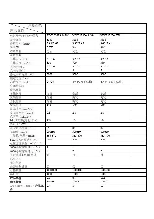
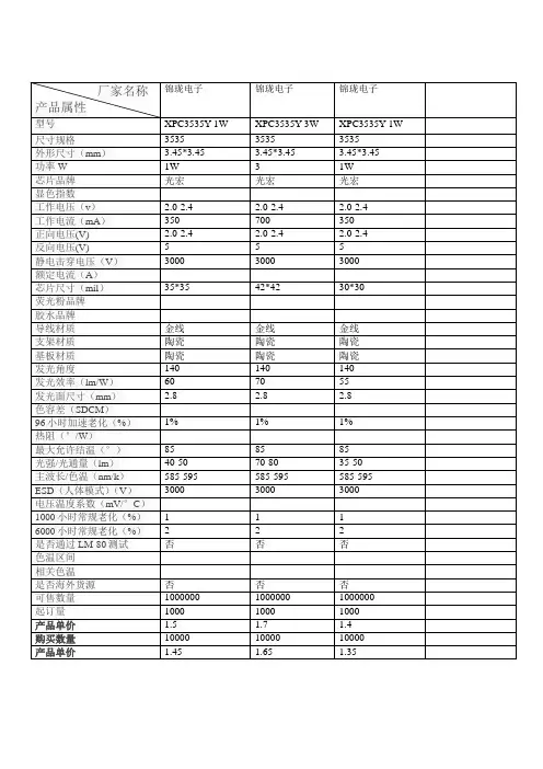
3535灯参数
- 格式:pdf
- 大小:390.07 KB
- 文档页数:10
承认书客户名称Client appellation:产品型号Model NO.: 3535RGB(晶元全彩)产品规格Specification: 3535 Top View LEDs样品编号NO.:、■特征:●宽角度全彩LED●支架有6个PIN脚●具有宽的发光角度●上锡方式:回流焊●抗静电●无铅●符合ROHS■描述 :●3535产品拥有宽的发光角度及高光效,该全彩产品采用蓝色、红色、绿色波长芯片加特殊工艺制作而成■用途:●背光●灯条●模组■外观描述:■封装尺寸1. 所有标注尺寸的单位均为毫米2. 除了特别注明,所有标注尺寸的公差均为±0.10mm█绝对最大额定值(Ta = 25℃)参数符号值单位正向电流IF 90 mA 峰值正向电流(Duty 1/10 @1KHz) IFP 100mA 功耗Pd 330 mW 操作温度Topr -40 to +85 ℃保存温度Tstg -40 to +90 ℃静电防护ESD 2000 V 回流焊最高温度Tsol 260±5 ℃反向电压VR 5 V 注明: *1:回流焊时间≦ 5 秒.█电性与光学特性(Ta=25℃)█信赖性测试项目与条件: 产品的可靠性应满足于下列项目:信任级别:90%Notes:Ivt: 信赖性测试前Iv值;Iv: 完成信赖性测试后Iv值;U:规格上限值L:规格下限值■使用说明1. 过电流保护客户必须使用电阻来保护,否则电压的漂移会引起电流的大幅度改变(发生击穿现象).灯珠使用时电流必须在规定范围之内,避免电流过大造成不良。
2. 储存2-1. 准备使用产品前不要打开防潮袋。
开封前请先检查包装袋有无漏气,开包后检查湿度标示卡20%RH 标示区有无由蓝色变为粉红色.如漏气或变色现象,请联系厂家或退回厂家高温除湿处理,(高温除湿环境:120度,6H)切勿自行处理2-2. 打开包装前,LEDs需储存在温度低于30℃,湿度低于70%RH 。
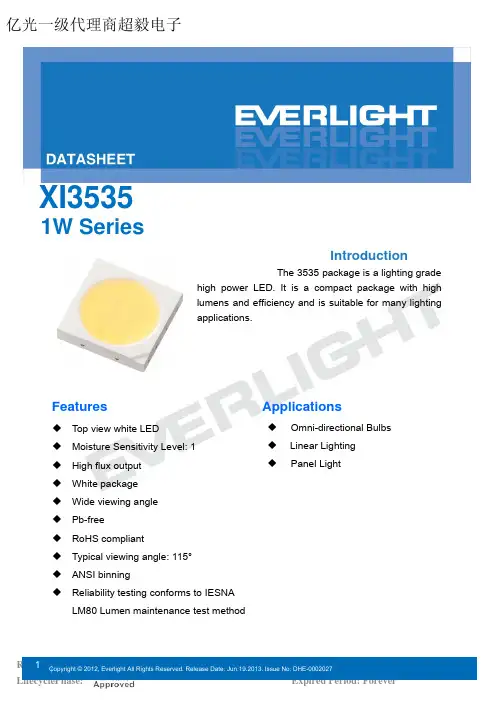
IntroductionThe 3535 package is a lighting gradehigh power LED.It is a compact package with high lumens and efficiency and is suitable for many lighting applications.FeaturesApplications◆Top view white LED ◆ Moisture Sensitivity Level: 1◆High flux output ◆White package ◆Wide viewing angle ◆Pb-free ◆RoHS compliant◆Typical viewing angle: 115°◆ANSI binning◆Reliability testing conforms to IESNA LM80 Lumen maintenance test method◆Omni-directional Bulbs ◆Linear Lighting ◆Panel LightXI35351W Series 亿光一级代理商超毅电子Table of ContentsProduct Nomenclature (3)Absolute Maximum Ratings (4)PN of the XI3535 series: Warm White LEDs (5)PN of the XI3535 series: Neutral White LEDs (6)PN of the XI3535 series: Cool White LEDs (7)Product Binning (8)Mechanical Dimension (16)Pad Configuration (16)Reflow Soldering Characteristics (18)Wavelength Characteristics (19)Typical Electrical Characteristics (19)Typical Relative Luminous Flux V.S. Forward Current (20)Typical Wavelength & Color Shift Characteristics (20)Typical Radiation Patterns (21)Emitter Tape Packaging (22)Emitter Reel Packaging (23)Product Labeling (23)Reliability Data (23)Storage Conditions (24)Revision History (26)Product NomenclatureThe product name is designated as below:XI3535– ABCDEFG–HIJKL–MNOPDesignation:AB = color [1]CD = color bin or CCT bin[1]E = Steps Mcadams binFG = min. luminous flux (lm) or radiation power (mW) performanceHI = forward voltage binJ = internal codeKL = power consumption[2]M = internal codeN = DamO = internal codeP =packaging type[3]Notes1.Table of color offerings:Color CCT range Color Rendering Index GT Cool-White4745~7050K>65KT Cool-White4745~7050K>80PT Cool-White4745~7050K>90HT Cool-White4745~7050K>93Warm-White2580~3710KLM>70Neutral-White3710K-4745KWarm White2580~3710K>80 KMNeutral-White3710K-4745KWarm White2580~3710K>90 PMNeutral-White3710K-4745KWarm White2580~3710K>93 HMNeutral-White3710K-4745K2.Table of power consumptions:Description011W3.Table of packaging types:DescriptionP TapeAbsolute Maximum RatingsMax. DC Forward Current (mA)IF350mA Max. Peak Pulse Current (mA)IPulse720mA Power Dissipation Pd1WThermal Resistance R th15°C/WOperating Temperature Topr-40 ~ +85°CStorage Temperature Tstg-40 ~ +100°CJunction temperature Tj115°C Max. Soldering Temperature T Sol260Notes:1.Maximum forward current for 1W is 350mA (Solder Pad=25°C).2.Duty cycle = 1/10@1KHZMin. LuminousFlux(lm)Typ.LuminousFlux(lm)CCT (K)Wavelength(nm)ForwardVoltage(V)ForwardCurrent(mA)CRI(Min.)XI3535-KM277F9-03201-000P9010027K-1,27K-227K-3,27K-42.95-3.8535080XI3535-KM307F9-03201-000P9010430K-1,30K-230K-3,30K-42.95-3.8535080XI3535-KM357F9-03201-000P9010535K-1,35K-235K-3,35K-42.95-3.8535080XI3535-HM307F8-03201-000P808430K-1,30K-230K-3,30K-42.95-3.8535093Notes:1.Luminous flux measurement tolerance: ±10%.2.The data of luminous flux measured at thermal pad=25°C3.Typical luminous flux or light output performance is operated within the condition guided by this datasheet4.The CRI value is based on the Everlight testing instrument.5.CRI measurement tolerance:±2.Min. LuminousFlux(lm)Typ.LuminousFlux(lm)CCT (K)Wavelength(nm)ForwardVoltage(V)ForwardCurrent(mA)CRI(Min.)XI3535-KM407F9-03201-000P9010740K-1,40K-240K-3,40K-42.95~3.8535080Notes:1.Luminous flux measurement tolerance: ±10%.2.The data of luminous flux measured at thermal pad=25°C3.Typical luminous flux or light output performance is operated within the condition guided by this datasheet4.The CRI value is based on the Everlight testing instrument.5.CRI measurement tolerance:±2.PN of the XI3535 series: Cool White LEDsMin. LuminousFlux(lm)Typ.LuminousFlux(lm)CCT (K)Wavelength(nm)ForwardVoltage(V)ForwardCurrent(mA)CRI(Min.)XI3535-KT507J1-03201-000P10011050K-1,50K-250K-3,50K-42.95-3.8535080XI3535-KT577J1-03201-000P10011157K-1,57K-257K-3,57K-42.95-3.8535080XI3535-KT607J1-03201-000P10010957K-2,57K-365K-1,65K-42.95-3.8535080XI3535-KT657J1-03201-000P10010865K-1,65K-265K-3,65K-42.95-3.8535080XI3535-PT577F9-03201-000P909757K-1,57K-257K-3,57K-42.95-3.8535090Notes:1.Luminous flux measurement tolerance: ±10%.2.The data of luminous flux measured at thermal pad=25°C3.Typical luminous flux or light output performance is operated within the condition guided by this datasheet4.The CRI value is based on the Everlight testing instrument.5.CRI measurement tolerance:±2.Product BinningLuminous Flux Bins14511001102562110120368312013048104130140510135140150613176150160717207160180820238180200E 92327J9200225127331225250233392250275339453275300445524300325552605325350660706350375770807375400880908400425F 990100K9425450White Bin StructureNotes:1.The CCT range of Cool-White varies from 4745K to 7050K.2.The CCT range of Neutral-White varies from 3710K to 4745K.3.The CCT range of Warm-White varies from 2580K to 3710K4.Color coordinates measurement allowance : ±0.015.Color bins are defined at I F =350mA operationCool-White Bin StructureChromaticity specification defined by ANSI亿光一级代理商超毅电子Cool-White Bin Coordinates5000K0.3460.3690.3380.3620.3450.3560.3370.3490.3530.3620.3450.35650K-10.3550.37650K-20.3460.369Reference Range: 4745~5000K Reference Range: 5000~5310K 0.3450.3560.3370.3490.3440.3430.3370.3370.3520.3490.3440.34350K-40.3530.36250K-30.3450.356Reference Range: 4745~5000K Reference Range: 5000~5310K 5700K0.3290.3540.3210.3460.3290.3420.3220.3350.3370.3490.3290.34257K-10.3380.36257K-20.3290.354Reference Range: 5310~5700K Reference Range: 5700~6020K CIE X CIE Y Bin CIE X CIE Y 0.3290.3420.3220.3350.3290.3310.3220.3240.3370.3370.3290.33157K-40.3370.34957K-30.3290.342Reference Range: 5310~5700K Reference Range: 5700~6020K 6000KCIE X CIE Y BinCIE X CIE Y 0.3210.3460.3120.3390.3220.3350.3130.3290.3290.3420.3210.33757K-20.3290.35465K-10.3210.348Reference Range: 5700~6020K Reference Range: 6020~6500K CIE X CIE Y Bin CIE X CIE Y 0.3220.3350.3130.3290.3220.3240.3150.3190.3290.3310.3220.32657K-30.3290.34265K-40.3210.337Reference Range: 5700~6020K Reference Range: 6020~6500K 6500KCIE X CIE Y BinCIE X CIE Y 0.3120.3390.3030.3300.3130.3290.3050.3210.3210.3370.3130.32965K-10.3210.34865K-20.3120.339Reference Range: 6020~6500K Reference Range: 6500~7050K 亿光一级代理商超毅电子0.3130.3290.3050.3210.3150.3190.3070.3110.3220.3260.3150.31965K-40.3210.33765K-30.3130.329Reference Range: 6020~6500KReference Range: 6500~7050KNote:1.Color coordinates measurement allowance : ±0.01.Neutral-White Bin StructureNeutral-White Bin Coordinates4000KCIE X CIE Y BinCIE X CIE Y 0.3870.3960.3740.3870.3830.3800.3700.3730.3950.3880.3830.38040K-10.4010.40440K-20.3870.396Reference Range: 3710~4000K Reference Range: 4000~4260K CIE X CIE Y Bin CIE X CIE Y 0.3830.3800.3700.3730.3780.3650.3670.3580.3900.3720.3780.36540K-40.3950.38840K-30.3830.380Reference Range: 3710~4000K Reference Range: 4000~4260K4500K0.3640.3810.3550.3740.3620.3660.3530.3600.3700.3730.3620.36645K-10.3740.38745K-20.3640.381Reference Range: 4260~4500K Reference Range: 4500~4745K 0.3620.3660.3530.3600.3590.3520.3510.3470.3670.3580.3590.35245K-40.3700.37345K-30.3620.366Reference Range: 4260~4500KReference Range: 4500~4745K Note:1.Color coordinates measurement allowance : ±0.01.Warm-White Bin StructureWarm-White Bin Coordinates2700KCIE X CIE Y BinCIE X CIE Y 0.469 0.429 0.4560.4260.459 0.4100.4470.4080.470 0.413 0.4590.41027K-10.481 0.43227K-20.4690.429Reference Range: 2580~2700K Reference Range: 2700~2870K CIE X CIE Y Bin CIE X CIE Y 0.459 0.410 0.447 0.408 0.448 0.3920.437 0.3890.459 0.394 0.448 0.392 27K-40.470 0.41327K-30.459 0.410Reference Range: 2580~2700K Reference Range: 2700~2870K 3000KCIE X CIE Y BinCIE X CIE Y 0.4430.4210.4300.4170.4350.4030.4220.3990.4470.4080.4350.40330K-10.4560.42630K-20.4430.421Reference Range: 2870~3000K Reference Range: 3000~3220K CIE X CIE Y Bin CIE X CIE Y 0.4350.4030.4220.3990.4260.3850.4150.3810.4370.3890.4260.38530K-40.4470.40830K-30.4350.403Reference Range: 2870~3000K Reference Range: 3000~3220K3500K0.4150.4090.4000.4020.4080.3920.3940.3850.4220.3990.4080.39235K-10.4300.41735K-20.4150.409Reference Range: 3220~3500K Reference Range: 3500~3710K 0.4080.3920.3940.3850.4020.3750.3890.3690.4150.3810.4020.37535K-40.4220.39935K-30.4080.392Reference Range: 3220~3500KReference Range: 3500~3710K Note:1.Color coordinates measurement allowance : ±0.01.Forward Voltage BinsV1 2.95 3.25V2 3.25 3.55V3 3.55 3.85Notes:1.Forward voltage measurement tolerance: ±0.1V.2.Forward voltage bins are defined at I F=350mA operation.Mechanical Dimension..4.2Notes:1.Dimensions are in millimeters.2.Tolerances unless mentioned are ±0.15mm.3.The thermal pad is electrically unity from the Anode and contact pads.4.Do not handle the device by the lens.Incorrect force applied to the lens may lead to the failure of devices.Pad ConfigurationTOP VIEW BOTTOM VIEWPAD FUNCTION1ANODE2CATHODEReflow Soldering CharacteristicsFor Reflow Processa.3535series are suitable for SMT processes.b.Curing of glue in oven must be according to standard operation flow processes.c.Reflow soldering should not be done more than twice.d.In soldering process, stress on the LEDs during heating should be avoided.e.After soldering, do not bend the circuit board.Wavelength CharacteristicsFor Cool-White,Warm-White Relative Spectral Distribution @ Solder Pad Temperature = 254005006007008000.00.20.40.60.81.0Warm-white-CRI>80 Nature-white-CRI>80 Cool-white-CRI>80 Warm-white-CRI>90 Cool-white-CRI>90R e l a t i v e L u m i n o u s I n t e n s t i yWavelength(nm)Typical Electrical CharacteristicsFor Cool-White,Warm-White @ Solder Pad Temperature = 25501001502002503003502.52.62.72.82.93.03.13.23.3F o r w a r d V o l t a g e (V )Forward Current(mA)Typical Relative Luminous Flux V.S. Forward CurrentFor Cool-White ,Warm-White @ Solder Pad Temperature = 250501001502002503003500.00.20.40.60.81.0R e l a t i v e L u m i n o u s I n t e n s i t yForward Current(mA)Typical Wavelength & Color Shift CharacteristicsV.S. Forward CurrentFor Cool-White , Warm-White @ Solder Pad Temperature = 2550100150200250300350200030004000500060007000Cool-White Warm-WhiteC C TForward Current(mA)Forward Current Derating Curve @ Junction Temperature <11520406080100100150200250300350400F o r w a r d C u r r e n t (m A )Soldering Temperature oCTypical Radiation Patterns3535 series:Typical Diagram Characteristics of Radiation for Warm-White andCool-White108090Notes:1.2θ1/2 is the off axis angle from lamp centerline where the luminous intensity is 1/2 of the peak value.2.View angle tolerance is ± 5∘.Emitter Tape Packaging MOQ>2Kpcs, multiple of 400pcs per reel,max 1600pcs MOQ <2Kpcs, multiple of 100pcs per reel,max 1600pcsEmitter Reel Packaging Reel DimensionsNotes:1.Dimensions are in millimeters.2.Tolerances unless mentioned are ±0.1mm.Product LabelingLabel ExplanationCPN: Customer Specification (when required)P/N : Everlight Production NumberQTY: Packing QuantityCAT: Luminous Flux (Brightness) BinHUE: Color BinREF: Forward Voltage BinLOT No: Lot NumberMADE IN TAIWAN: Production PlaceReliability DataReflow Tsol=260 , 10sec 3 timesThermal ShockH 100 20min.'∫ 10sec.'L 10 20min.500,1000 CyclesPower Temperature Cycle H 85 15min.'∫ 5min.'L 40 15min.IF=350mA500,1000 CyclesHigh Temperature/HumidityOperationTa=85 , RH=85%, IF=225mA1000hoursRoom Temperature OperationLifeTa=25 , IF=350mA1000hoursHigh Temperature OperationLife #1Ta=55 , IF=350mA1000hoursHigh Temperature OperationLife #2Ta=85 , IF=225mA1000hoursLow Temperature OperationLifeTa=-40 , IF=350mA1000hoursPulse 30ms ON/2500ms OFF / 30000 CyclesIF=720mA30ms ON/2500ms OFF /30000 CyclesFailure Criteria:1.LEDs are open or shorted2.lm: luminous flux attenuate difference(1000hrs)>50%3.VF: forward voltage difference(1000hrs)>20%Storage Conditions⏹Before the package is opened: The LEDs should be stored at 30°C or less and 50%RH or less after beingshipped from Everlight.The storage life is6 months. If the LEDs are to be stored for more than 6months, they should be stored in a sealed container with a nitrogen atmosphere and moisture absorbent material.⏹After opening the package: The LED's should be stored under 30 or less and 30%RH or less. The LEDshould be used within 168hrs (7days) after opening the package. If unused LEDs remain, they should be stored in moisture proof packages.⏹Before using LEDs: The LEDs should be baked under the following conditions: pre-curing at 60±5 for 24hours.⏹Do not stack assemblies containing Everlight XI3535 LEDs to prevent damage to the optical surface ofLEDs. Forces applied to the optical surface may result in the surface being damaged.Revision HistoryCurrent version: 06.19.2013Issue No:DHE-0002027Version: 10Created by: Betty HongP5,P6,P7New 3000K 4000K 5000K Series.2012-12-07 P7New XI3535-KT657J1-03201-000P2013-02-07 P4Change the Max. Peak Pulse Current2013-03-13 P5,P7Create New CRI>90 spec2013-03-26P21MOQ>2Kpcs, multiple of 400pcs per reelMOQ <2Kpcs, multiple of 100pcs per reel2013-04-09P23Create Reliability Data2013-04-18 P21Create Package Quantity max 1600pcs2013-05-28 P5,P7Added the 4000K and 6000K Color06-19-2013。
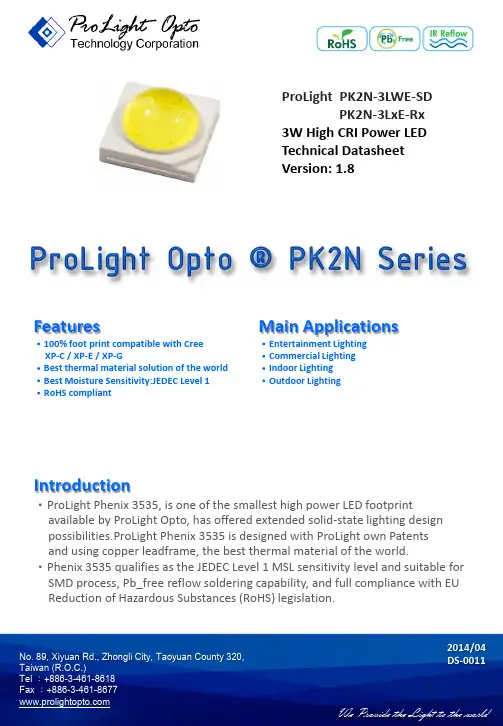
ProLight PK2N-3LWE-SD PK2N-3LxE-Rx 3W High CRI Power LED Technical Datasheet Version: 1.8Features‧100% foot print compatible with CreeXP-C / XP-E / XP-G‧Best thermal material solution of the world ‧Best Moisture Sensitivity:JEDEC Level 1‧RoHS compliant Main Applications ‧Entertainment Lighting‧Commercial Lighting‧Indoor Lighting‧Outdoor LightingIntroduction‧ProLight Phenix 3535, is one of the smallest high power LED footprintavailable by ProLight Opto, has offered extended solid-state lighting designpossibilities.ProLight Phenix 3535 is designed with ProLight own Patentsand using copper leadframe, the best thermal material of the world.‧Phenix 3535 qualifies as the JEDEC Level 1 MSL sensitivity level and suitable for SMD process, Pb_free reflow soldering capability, and full compliance with EU Reduction of Hazardous Substances (RoHS) legislation.2014/04No. 89, Xiyuan Rd., Zhongli City, Taoyuan County 320,Emitter Mechanical DimensionsNotes:1. The cathode side of the device is denoted by the chamfer on the part body.2. Electrical insulation between the case and the board is required. Do not electrically connecteither the anode or cathode to the slug.3. Drawing not to scale.4. All dimensions are in millimeters.5. Unless otherwise indicated, tolerances are ± 0.10mm.6. Please do not solder the emitter by manual hand soldering, otherwise it will damage the emitter.7. Please do not use a force of over 0.3kgf impact or pressure on the lens of the LED, otherwiseit will cause a catastrophic failure.*The appearance and specifications of the product may be modified for improvement without notice.2No. 89, Xiyuan Rd., Zhongli City, Taoyuan County 320,No. 89, Xiyuan Rd., Zhongli City, Taoyuan County 320, Forward Voltage V F (V)Forward Voltage V F (V)Thermal Resistance @ 350mARefer @700mAJunction to SlugColorMin. Typ. Max.Typ.(°C/ W)White 2.85 3.2 3.85 3.6 8 Warm White2.853.23.85 3.68●ProLight maintains a tolerance of ± 0.1V for Voltage measurements.ColorPart Number EmitterLumious Flux ΦV (lm)CRITypical @350mA Refer @700mAMinimum Typical Minimum TypicalWhite PK2N-3LWE-SD 120 141 204 250 74 Warm White PK2N-3LVE-R7 100 123 170 218 73 White PK2N-3LWE-R8 100 120 170 213 84 Warm White PK2N-3LVE-R8 90 112 153 199 82 Warm WhitePK2N-3LVE-R9570 9011916095●ProLight maintains a tolerance of ± 10% on flux and power measurements.● Please do not drive at rated current more than 1 second without proper heat sink.3Flux Characteristics, T J = 25°CElectrical Characteristics, T J = 25°COptical Characteristics at 350mA, T J = 25°CTotalincluded Viewing Angle Angle Radiation ColorColor Temperature CCT (degrees) (degrees) PatternMin. Typ. Max.θ0.90V2 θ1/2 LambertianWhite 4100 K 5500 K 10000 K 160 130 Warm White2700 K3300 K4100 K160130●ProLight maintains a tolerance of ± 5% for CCT measurements.No. 89, Xiyuan Rd., Zhongli City, Taoyuan County 320, ParameterWhite/Warm WhiteDC Forward Current (mA)700Peak Pulsed Forward Current (mA) 1000 (less than 1/10 duty cycle@1KHz)Average Forward Current (mA) 700ESD Sensitivity±4000V (Class III)(HBM per MIL-STD-883E Method 3015.7) LED Junction Temperature 120°C Operating Board Temperature -40°C - 90°Cat Maximum DC Forward Current Storage Temperature -40°C - 120°C Soldering Temperature JEDEC 020c 260°CAllowable Reflow Cycles 3Reverse VoltageNot designed to be driven in reverse bias4Absolute Maximum RatingsPhotometric Luminous Flux Bin Structure at 350mAColor Bin CodeMinimum Maximum Available Photometric Flux (lm) Photometric Flux (lm) Color BinsPK2N-3LWE-SD V2 120 130 【1】W1 130 140 AllW2 140 155 Xx,Wx,Vx【1】X1 155 170 【1】PK2N-3LVE-R7 U2 100 110 【1】V1 110 120 All V2 120 130 All W1 130 140 【1】PK2N-3LWE-R8 U2 100 110 【1】V1 110 120 AllV2 120 130 Xx,Wx,Vx【1】W1 130 140 【1】PK2N-3LVE-R8 U1 90 100 【1】U2 100 110 All V1 110 120 All V2 120 130 【1】PK2N-3LVE-R95 T1 70 80 All T2 80 90 All U1 90 100 All U2 100 110 【1】●ProLight maintains a tolerance of ± 10% on flux and power measurements.●The flux bin of the product may be modified for improvement without notice.●【1】The rest of color bins are not 100% ready for order currently. Please ask for quote and order possibility.5No. 89, Xiyuan Rd., Zhongli City, Taoyuan County 320,No. 89, Xiyuan Rd., Zhongli City, Taoyuan County 320, 6White and Warm White Binning Structure Graphical Representation0.260.28 0.30 0.320.340.360.380.400.420.440.460.48 0.260.28 0.30 0.32 0.34 0.36 0.38 0.40 0.42 0.44 0.46 0.48 0.50yx10000 K7000 K6300 K5650 K5000 K4500 K4100 K3800 K3500 K3250 K3050 K2850 K2700 KR0Q0R1P0P1M0M1N0N1Y0YATNT0UNU0V0VNX0XPXNW0WN WPQ1S0S1Planckian (BBL)Warm WhiteWhiteNo. 89, Xiyuan Rd., Zhongli City, Taoyuan County 320, Bin Codexy Typ. CCT (K)Bin CodexyTyp. CCT (K)T00.378 0.382 4300WN0.329 0.345 5970 0.374 0.366 0.316 0.333 0.360 0.357 0.315 0.344 0.362 0.3720.329 0.357 TN0.382 0.3974300 WP0.3290.3315970 0.378 0.382 0.329 0.320 0.362 0.372 0.318 0.310 0.365 0.386 0.317 0.320 U00.3620.3724750X00.3080.3116650 0.360 0.357 0.305 0.322 0.344 0.344 0.316 0.3330.346 0.3590.3170.320UN0.365 0.386 4750 XN0.305 0.322 6650 0.362 0.372 0.303 0.333 0.346 0.359 0.315 0.344 0.347 0.372 0.316 0.333 V00.329 0.3315320XP0.3080.3116650 0.329 0.345 0.317 0.320 0.346 0.359 0.319 0.300 0.344 0.3440.3110.293VN0.3290.3455320Y0 0.308 0.311 8000 0.329 0.357 0.283 0.284 0.347 0.372 0.274 0.301 0.346 0.3590.303 0.333 W00.3290.3455970 YA0.3080.3118000 0.329 0.331 0.311 0.293 0.317 0.320 0.290 0.2700.3160.3330.2830.284●Tolerance on each color bin (x , y) is ± 0.01Note: Although several bins are outlined, product availability in a particular bin varies by production run and by product performance. Not all bins are available in all colors.7White Bin StructureNo. 89, Xiyuan Rd., Zhongli City, Taoyuan County 320, Bin Codexy Typ. CCT (K)Bin Code xyTyp. CCT(K) M00.453 0.416 2770 Q00.4090.4003370 0.444 0.399 0.4020.382 0.459 0.403 0.4160.389 0.467 0.419 0.4240.407 M10.4600.430 2770 Q10.4140.4143370 0.453 0.416 0.4090.400 0.467 0.419 0.4240.4070.4730.432 0.4300.421N00.438 0.412 2950 R00.392 0.391 3650 0.429 0.394 0.3870.374 0.444 0.399 0.402 0.382 0.453 0.416 0.4090.400 N10.4440.426 2950 R10.4140.4143650 0.438 0.412 0.4090.400 0.453 0.416 0.3920.391 0.460 0.430 0.397 0.406P00.4240.407 3150 S00.3920.391 3950 0.416 0.389 0.3870.374 0.429 0.394 0.3740.366 0.438 0.412 0.378 0.382 P10.4300.421 3150 S10.3970.4063950 0.424 0.407 0.3920.391 0.438 0.412 0.3780.3820.4440.4260.3820.397●Tolerance on each color bin (x , y) is ± 0.01Note: Although several bins are outlined, product availability in a particular bin varies by production run and by product performance. Not all bins are available in all colors.8Warm White Bin StructureForward Voltage Bin Structure at 350mAColor Bin Code Minimum Voltage (V) Maximum Voltage (V)White A 2.85 3.10B 3.10 3.35D 3.35 3.60E 3.60 3.85Warm White A 2.85 3.10B 3.10 3.35D 3.35 3.60E 3.60 3.85●ProLight maintains a tolerance of ± 0.1V for Voltage measurements.Note: Although several bins are outlined, product availability in a particular bin varies by production runand by product performance. Not all bins are available in all colors.No. 89, Xiyuan Rd., Zhongli City, Taoyuan County 320,9No. 89, Xiyuan Rd., Zhongli City, Taoyuan County 320, 0.00.20.4 0.6 0.8 1.0350 400 450 500 550 600 650 700 750 800 850R e l a t i v e S p e c t r a l P o w e r D i s t r i b u t i o nWavelength (nm)Standard Eye Response CurveWarm White0.00.20.4 0.6 0.8 1.0350 400 450 500 550 600 650 700 750 800 850R e l a t i v e S p e c t r a l P o w e r D i s t r i b u t i o nWavelength (nm)Standard Eye Response CurveWhiteWarm White2. White 、Warm White For R8Standard Eye Response Curve White10Color Spectrum, T J = 25°C1. White 、Warm White For R73. Warm White For R950.00.20.4 0.6 0.8 1.0 350 400 450 500 550 600 650 700 750 800 850R e l a t i v e S p e c t r a l P o w e r D i s t r i b u t i o nWavelength (nm)Standard Eye Response CurveWhiteWarm WhiteNo. 89, Xiyuan Rd., Zhongli City, Taoyuan County 320, 0.00.2 0.4 0.6 0.8 1.0 1.2 1.4 1.6 1.8 2.0 0200 400 600 800R e l a t i v e L u m i n o u s F l u xForward Current (mA)100 200 300 400 500 600 700 8000 0.5 1 1.5 2 2.5 3 3.5 4A v e r a g e F o r w a r d C u r r e n t (m A )Forward Voltage (V)11Light Output CharacteristicsRelative Light Output vs. Junction Temperature at 700mAForward Current Characteristics, T J = 25°CFig 1. Forward Current vs. Forward Voltage for White, Warm White.Fig 2. Relative Luminous Flux vs.Forward Current for White, Warm White at T J =25 maintained.0 20 40 60 80 100 120 140 160 020406080100120R e l a t i v e L i g h t O u t p u t (%)Junction Temperature, T J (℃)White, Warm WhiteNo. 89, Xiyuan Rd., Zhongli City, Taoyuan County 320, 0 100 200 300 400 500 600 700 800 0255075100125150F o r w a r d C u r r e n t (m A )Ambient Temperature (℃)R θJ-A = 30°C/W R θJ-A = 25°C/W R θJ-A = 15°C/WR θJ-A = 20°C/W 12Ambient Temperature vs. Maximum Forward Current1. White, Warm White (T JMAX = 120°C)Typical Representative Spatial Radiation PatternLambertian Radiation Pattern0 10 20 30 40 50 60 70 80 90 100 -100-80-60-40 -20 0 20 406080100R e l a t i v e I n t e n s i t y (%)Angular Displacement (Degrees)Soak RequirementsLevel Floor Life Standard Accelerated Environment Time Conditions Time (hours) Conditions Time (hours) Conditions1 Unlimited ≤30°C /168 +5/-085°C /NA NA 85% RH 85% RH●The standard soak time includes a default value of 24 hours for semiconductor manufature'sexposure time (MET) between bake and bag and includes the maximum time allowed out ofthe bag at the distributor's facility.●Table below presents the moisture sensitivity level definitions per IPC/JEDEC's J-STD-020C.Soak Requirements Level Floor Life Standard Accelerated Environment Time Conditions Time (hours) Conditions Time (hours) Conditions1 Unlimited ≤30°C /168 +5/-085°C /NA NA 85% RH 85% RH2 1 year ≤30°C /168 +5/-085°C /NA NA 60% RH 60% RH2a 4 weeks ≤30°C /696 +5/-030°C /120 +1/-060°C / 60% RH 60% RH 60% RH3 168 hours ≤30°C /192 +5/-030°C /40 +1/-060°C / 60% RH 60% RH 60% RH4 72 hours ≤30°C /96 +2/-030°C /20 +0.5/-060°C / 60% RH 60% RH 60% RH5 48 hours ≤30°C /72 +2/-030°C /15 +0.5/-060°C / 60% RH 60% RH 60% RH5a 24 hours ≤30°C /48 +2/-030°C /10 +0.5/-060°C / 60% RH 60% RH 60% RH6 Time on Label ≤30°C / Time on Label 30°C /NA NA (TOL) 60% RH (TOL) 60% RHMoisture Sensitivity Level - JEDEC Level 1No. 89, Xiyuan Rd., Zhongli City, Taoyuan County 320,13Stress Test Stress ConditionsStressDurationFailure CriteriaRoom Temperature25°C, I F = max DC (Note 1) 1000 hours Note 2 Operating Life (RTOL)Wet High Temperature85°C/60%RH, I F = max DC (Note 1) 1000 hours Note 2 Operating Life (WHTOL)Wet High Temperature85°C/85%RH, non-operating 1000 hours Note 2 Storage Life (WHTSL)High Temperature110°C, non-operating 1000 hours Note 2 Storage Life (HTSL)Low Temperature-40°C, non-operating 1000 hours Note 2 Storage Life (LTSL)Non-operating -40°C to 120°C, 30 min. dwell,200 cycles Note 2 Temperature Cycle (TMCL) <5 min. transferNon-operating -40°C to 120°C, 20 min. dwell,200 cycles Note 2 Thermal Shock (TMSK) <20 sec. transferMechanical Shock 1500 G, 0.5 msec. pulse,Note 3 5 shocks each 6 axisNatural Drop On concrete from 1.2 m, 3X Note 3 Variable Vibration 10-2000-10 Hz, log or linear sweep rate,Note 3 Frequency 20 G about 1 min., 1.5 mm, 3X/axisSolder Heat Resistance260°C ± 5°C, 10 sec. Note 3 (SHR)Solderability Steam age for 16 hrs., then solder dip Solder coverage at 260°C for 5 sec. on leadNotes:1. Depending on the maximum derating curve.2. Criteria for judging failureItem Test Condition Criteria for Judgement Min. Max.Forward Voltage (V F) I F = max DC -- Initial Level x 1.1Luminous Flux orI F = max DC Initial Level x 0.7 --Radiometric Power (ΦV)Reverse Current (I R) V R = 5V -- 50 μA* The test is performed after the LED is cooled down to the room temperature.3. A failure is an LED that is open or shorted.Qualification Reliability TestingNo. 89, Xiyuan Rd., Zhongli City, Taoyuan County 320,14No. 89, Xiyuan Rd., Zhongli City, Taoyuan County 320, TYPE A.15Recommended Solder Pad DesignStandard Emitter ●All dimensions are in millimeters.● Electrical isolation is required between Slug and Solder Pad.TYPE B.No. 89, Xiyuan Rd., Zhongli City, Taoyuan County 320, 16Reflow Soldering ConditionProfile Feature Sn-Pb Eutectic AssemblyPb-Free Assembly Average Ramp-Up Rate3°C / second max.3°C / second max.(T Smax to T P ) Preheat– Temperature Min (T Smin ) 100°C 150°C – Temperature Max (T Smax ) 150°C 200°C – Time (t Smin to t Smax ) 60-120 seconds 60-180 seconds Time maintained above:– Temperature (T L ) 183°C 217°C – Time (t L ) 60-150 seconds 60-150 secondsPeak/Classification Temperature (T P ) 240°C 260°C Time Within 5°C of Actual Peak10-30 seconds20-40 seconds Temperature (t P ) Ramp-Down Rate 6°C/second max. 6°C/second max. Time 25°C to Peak Temperature 6 minutes max.8 minutes max.● We recommend using the M705-S101-S4 solder paste from SMIC (Senju Metal Industry Co., Ltd.) for lead-free soldering.● Do not use solder pastes with post reflow flux residue>47%. (58Bi-42Sn eutectic alloy, etc) This kind of solder pastes may cause a reliability problem to LED.● All temperatures refer to topside of the package, measured on the package body surface.● Repairing should not be done after the LEDs have been soldered. When repairing is unavoidable, a double-head soldering iron should be used. It should be confirmed beforehand whether the characteristics of the LEDs will or will not be damaged by repairing. ● Reflow soldering should not be done more than three times. ● When soldering, do not put stress on the LEDs during heating. ● After soldering, do not warp the circuit board.t 25°C to Peakt S PreheatTimeT e m p e r a t u r eCritical Zone T L to T PRamp-upRamp-downT SmaxT Smint Pt LT PT L25IPC-020cNotes:1. Drawing not to scale.2. All dimensions are in millimeters.3. Unless otherwise indicated, tolerances are ± 0.10mm.17 No. 89, Xiyuan Rd., Zhongli City, Taoyuan County 320,No. 89, Xiyuan Rd., Zhongli City, Taoyuan County 320, 18Notes:1. Empty component pockets sealed with top cover tape.2. 250, 500 and 1000 pieces per reel.3. Drawing not to scale.4. All dimensions are in millimeters.178 ± 13 ± 0.54 ± 0.5 5 ± 0.560 ± 0.513.2 ± 0.516.2 ± 0.5Φ 13.1 ± 0.5Φ 21 ± 0.5No. 89, Xiyuan Rd., Zhongli City, Taoyuan County 320, 19Precaution for UseHandling of Silicone Lens LEDsNotes for handling of silicone lens LEDs● Please do not use a force of over 0.3kgf impact or pressure on the silicone lens, otherwise it will cause a catastrophic failure.● The LEDs should only be picked up by making contact with the sides of the LED body. ● Avoid touching the silicone lens especially by sharp tools such as Tweezers. ● Avoid leaving fingerprints on the silicone lens.● Please store the LEDs away from dusty areas or seal the product against dust. ● When populating boards in SMT production, there are basically no restrictions regarding the form of the pick and place nozzle, except that mechanical pressure on the silicone lens must be prevented.● Please do not mold over the silicone lens with another resin. (epoxy, urethane, etc)●StoragePlease do not open the moisture barrier bag (MBB) more than one week. This may cause the leads of LED discoloration. We recommend storing ProLight’s LEDs in a dry box after opening the MBB. The recommended storage conditions are temperature 5 to 30°C and humidity less than 40% RH. It is also recommended to return the LEDs to the MBB and to reseal the MBB. ● The slug is is not electrically neutral. Therefore, we recommend to isolate the heat sink.● We recommend using the M705-S101-S4 solder paste from SMIC (Senju Metal Industry Co., Ltd.) for lead-free soldering.● Do not use solder pastes with post reflow flux residue>47%. (58Bi-42Sn eutectic alloy, etc) This kind of solder pastes may cause a reliability problem to LED.● Any mechanical force or any excess vibration shall not be accepted to apply during cooling process to normal temperature after soldering. ● Please avoid rapid cooling after soldering.● Components should not be mounted on warped direction of PCB.● Repairing should not be done after the LEDs have been soldered. When repairing is unavoidable, a heat plate should be used. It should be confirmed beforehand whether the characteristics of the LEDs will or will not be damaged by repairing.● This device should not be used in any type of fluid such as water, oil, organic solvent and etc. When cleaning is required, isopropyl alcohol should be used.● When the LEDs are illuminating, operating current should be decide after considering the package maximum temperature.● The appearance, specifications and flux bin of the product may be modified for improvement without notice. Please refer to the below website for the latest datasheets. /。
产品承认书产品名称:3535双波紫外杀菌灯珠5-8mw产品型号:XL-3535UV2SB12P2客户名称:客户料号:承认日期:深圳市成兴光电子科技有限公司制定审核核准客户承认栏确认审核核准目录1.产品特性2.应用领域3.产品参数4.极限使用条件5.产品规格6.典型特性曲线7.产品包装与运输8.焊接建议9.使用建议和说明10.免责声明产品规格书1.产品特性◆高光输出功率;◆寿命长,低光衰;◆环保,节能,高可靠性;◆耐用,防冲击,易设计,适合在多领域应用;◆内置UVA+UVC 双波长芯片,独特设计应用更广泛;2.应用领域◆杀菌消毒;◆空气和水净化;◆紫外探测与通讯技术;◆食品加工保鲜、食品饮料的包装,生鲜储存等;◆医疗卫生,皮肤病治疗等;3.产品参数类型参数符号测试条件最小值典型值最大值单位UVC正向电压Vf1If =50mA 4.568V Vf3If=10uA 4——V 反向电流Ir Vr =-5V —— 1.0uA 反向电压Vr Ir=-10μA 10——V 辐射功率Φe If =50mA 5—8mw 峰值波长WLP If =50mA 260—280nm 半波宽HW If =50mA 8--14nm UVA正向电压Vf1If =60mA 3.0— 3.3V Vf3If=10uA 2.2——V 反向电流Ir Vr =-10V —— 1.0uA 反向电压Vr Ir=-10μA 5——V 辐射功率Φe If =60mA 15—60mw 峰值波长WLPIf =60mA390—410nm注:◆产品测试环境@Tc=22℃;◆可根据客户要求定制特殊规格产品,可根据客户要求对产品参数进行细分;◆上述特性数据源自深圳市成兴光电子科技有限公司测量设备,其正向电压、峰值波长、辐射功率的测量误差分别为±0.2V、±3nm 和±10%;◆本产品详细参数之分类细则及标签代码命名规则将另行提供。

产 品 规 格 书 Product Specification文件编号 Document number WE-WI-RD-962 版本版次Version editionA/0产品名称 Product name 3535内封ICN302B7产品规格Product specificationWE-3535AY0203Z-001文件编制 Documentation 马明海 批准发行Approved issue马小其客户服务 Custormer Service 联系电话 Contact number客户名称 Customer name 样品编号 Sample number产品验证 Product verification批准承认 Recognition approval注: 1.此规格书以中英文方式书写,若有冲突以中文版文本为准。
/This specification is written in both Chinese and English. In case of conflict, the Chinese version shall prevail.2.此规格书的最终解释权归由本公司。
/The final interpretation of this specification shall be vested in the company.目 录Catalog0.0、封面/co ver ..........................................................................第1页page 10.1、目录/Catalog ......................................................................... 第2页page 21、产品概述/Product Overview ..............................................................第3页page 32、功能特点/Functional characteristics.....................................................第3页page 33、应用领域/Application area ..............................................................第3页page 34、外观描述 /Appearance description ......................................................第4页page 45、封装尺寸/Size .........................................................................第4页page 46、脚位图/Foot map .........................................................................第5页page 5第5页page 5 7、最大额定值/MaximumRating ............................................................第6页page 6 8、推荐工作范围/Recommended scope ofwork .................................................9、电气参数/Electrical parameters..........................................................第6页page 610、开关特性/Switching第7页page 7 characteristics.....................................................11、内置LED参数/Built-in LED parameters..................................................第7页page 712、功能说明/Description of functions......................................................第7页page 713、恒流曲线/Constant-current第10页page 10 curve........................................................14、应用线路图/Application Route Diagram..................................................第10页page 1015、使用注意事项/Precautions ............................................................第11页page 111、产品概述/Product Overview:N302B7-3535RGB是一款集成高质量单线级联恒流驱动IC N302B7和高质量RGB LED芯片的外控恒流3535集成灯珠。
LED3535是一种LED灯带,其命名来源于它的尺寸规格,即3.5毫米宽。
这种灯带通常用于装饰和照明应用,如广告牌、展示柜、家居照明等。
LED3535灯带的标准包括以下几个方面:
1. 尺寸:LED3535灯带的宽度为3.5毫米,长度可以根据需要定制,通常为1米或1.5米。
2. LED数量:LED3535灯带通常包含30个LED灯,也有其他规格的灯带,如10个或60个LED 灯。
3. 颜色:LED3535灯带通常有红、绿、蓝、白等多种颜色,可以根据需要选择。
4. 功率:LED3535灯带的功率通常为0.5W/米,这意味着每米灯带消耗0.5瓦的电力。
5. 工作电压:LED3535灯带通常工作在直流12V或24V的电压下。
6. 发光效率:LED3535灯带的发光效率通常在80-90lm/W左右。
7. 使用寿命:LED3535灯带的使用寿命通常在5万小时左右。
8. 防水等级:LED3535灯带通常具有IP65的防水等级,可以抵抗一般的湿气和雨水。
以上就是LED3535灯带的一些基本标准,实际购买和使用时,还需要根据具体的应用场景和需求,选择合适的LED3535灯带。
深圳市拓展光电有限公司SHENZHEN DEVELOPMENT PHOTOELECTRIC CO., LTD SPECIFICATION Model: TZ35UVB02-059Date: 2022/5/24NO:SZTZ-DS-110Par NO: F.35.00110版本修订日期文件修订内容备注A02022/5/24首次发行林纬正制作宁鹏宇日期2022年5月24日核准林纬正日期2020年5月24日版本号A0受控日期2020年5月24日The 3535 LED light source is a high-performance energy-saving device that can handle high heat and high drivecurrent.此款3535 LED光源是一种高性能节能器件,可以处理高热量和高驱动电流。
The Purple LED light source with peak wavelength rangingfrom 300nm to315nm.紫外LED光源峰值波长为300nm ~315nm.This part has a foot print that is compatible to most of thesame size LED in the market today.此器件的焊盘兼容当今市场上大部分相同大小的LED。
FEATURES/特点n Deep UV LED with emissionwavelength between 300nm to 310nm具有发射波长的深紫外光LED在300nm至315nm.n Compatible with reflow solderingprocess兼容回流焊工艺n Low thermal resistance/热阻低n Wide viewing angle at 60°60° 大发光角度n Superior ESD protection优越的ESD保护n Environmental friendly, RoHScompliance材质环保,符合RoHS要求Note: The information in this document is subject to change without notice.注:本文件中的信息如有变更,恕不另行通知。