
LL1105SF065Q;中文规格书,Datasheet资料
- 格式:pdf
- 大小:198.78 KB
- 文档页数:2

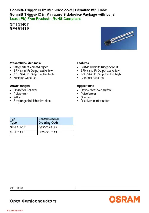
SFH 5140 F SFH 5141 FSchmitt-Trigger IC im Mini-Sidelooker Gehäuse mit LinseSchmitt-Trigger IC in Miniature Sidelooker Package with LensLead (Pb) Free Product - RoHS Compliant2007-04-031Wesentliche Merkmale •Integrierter Schmitt-Trigger •SFH 5140 F: Output active low •SFH 5141 F: Output active high •Miniatur-GehäuseAnwendungen •Optischer Schalter •Pulsformer •Zähler•Empfänger in LichtschrankenTyp Type Bestellnummer Ordering Code SFH 5140 F Q62702P5112SFH 5141 FQ62702P5113Features •Built-in Schmitt Trigger circuit •SFH 5140 F: Output active low •SFH 5141 F: Output active high •Compact packageApplications •Optical threshold switch •Pulseformer •Counter•Receiver in interrupters2007-04-032Zur Stabilisierung der Versorgung wird ein Stützkondensator (angeschlossen zwischen V CC und GND) von typ. 0.1 µF empfohlen.A bypass capacitor, 0.1 µF typical, connected between V CC and GND is recommended in order to stabilize power supply line.Grenzwerte (T A = 25 °C) Maximum Ratings Bezeichnung ParameterSymbol SymbolWert Value Einheit UnitBetriebs- und LagertemperaturOperating and storage temperature range T op ; T stg – 40 … + 85°CVersorgungsspannung Supply voltage V CC – 0.5 … + 20V Ausgangsspannung Output voltage V O – 0.5 … + 20V Ausgangsstrom Output current I O 50mA Verlustleistung Power dissipationP tot175mWEmpfohlener ArbeitsbereichRecommended Operating Conditions Bezeichnung ParameterSymbol SymbolWert Value Einheit Unit Versorgungspannung Supply voltage V CC 4 … 18V Ausgangsstrom Output currentI O< 16mAKennwerte (T A = 25 °C, V CC = 5 V) Characteristics Bezeichnung ParameterSymbol SymbolWert ValueEinheit Unit Ausgangsspannung …high“ Output voltage “high” I O = 0V OH V CC (> 4.0)VAusgangsspannung …low“ Output voltage “low” I O = 16 mAV OL0.15 (< 0.4)V2007-04-033Stromaufnahme Supply current V CC = 5 V V CC = 18 V I CC3.3 (< 5) 5.0mAHysterese Hysteresis E e, OFF /E e, ON0.6(0.5 … 0.9)–Halbwinkel Half angleϕ± 12Grad degr.Anstiegszeit 10% bis 90% Rise time 10% to 90%R L = 280 Ω, E e = 90 µW/cm 2, λ = 950 nm t r100nsAbfallzeit 90% bis 10% Fall time 90% to 10%R L = 280 Ω, E e = 90 µW/cm 2, λ = 950 nm t f100nsAusgangsverzögerungszeitPropagation delay time “H” → “L”R L = 280 Ω, E e = 90 µW/cm 2, λ = 950 nm t PHL5 (< 15) µsAusgangsverzögerungszeitPropagation delay time “L” → “H”R L = 280 Ω, E e = 90 µW/cm 2, λ = 950 nmt PLH5 (< 15) µsDie Schmitt-Trigger ICs werden nach ihrer Schaltschwelle gruppiert und mit arabischen Ziffern gekennzeichnet.The schmitt-triggers ICs are grouped according to their threshold and distinguished by arabian figures.Bezeichnung ParameterSymbol SymbolWert Value Einheit Unit12345Schaltschwelle, λ = 950 nm ThresholdSFH 5140 F: “H” → “L” SFH 5141 F: “L” → “H”E e, ON 4 (8)6.3 ...12.510 (20)16 (32)25 (50)µW/cm 2Kennwerte (T A = 25 °C, V CC = 5 V) Characteristics (cont’d)Bezeichnung Parameter Symbol SymbolWert Value Einheit UnitFigure 1Block DiagramFigure 2Test Circuit for Switching and Response TimeFigure 3Switching Time Definitions2007-04-034Relative ThresholdEe,ON/E e,ON (V cc = 5 V) = f (V CC)Output Voltage VSupply CurrentICC= f (V CC)Supply Current vs. AmbientTotal Power DissipationPtot= f (T A)2007-04-035MaßzeichnungPackage OutlinesMaße in mm (inch) / Dimensions in mm (inch).2007-04-036LötbedingungenSoldering ConditionsWellenlöten (TTW)(nach CECC 00802)Published byOSRAM Opto Semiconductors GmbHWernerwerkstrasse 2, D-93049 Regensburg© All Rights Reserved.Attention please!The information describes the type of component and shall not be considered as assured characteristics.Terms of delivery and rights to change design reserved. Due to technical requirements components may contain dangerous substances. For information on the types in question please contact our Sales Organization.PackingPlease use the recycling operators known to you. We can also help you – get in touch with your nearest sales office. By agreement we will take packing material back, if it is sorted. You must bear the costs of transport. For packing material that is returned to us unsorted or which we are not obliged to accept, we shall have to invoice you for any costs incurred.Components used in life-support devices or systems must be expressly authorized for such purpose! Critical components 1 may only be used in life-support devices or systems 2 with the express written approval of OSRAM OS.1 A critical component is a component used in a life-support device or system whose failure can reasonably be expected to cause the failure of that life-support device or system, or to affect its safety or effectiveness of that device or system.2 Life support devices or systems are intended (a) to be implanted in the human body, or (b) to support and/or maintain and sustain human life. If they fail, it is reasonable to assume that the health of the user may be endangered.2007-04-037分销商库存信息: OSRAMSFH 5140 F。
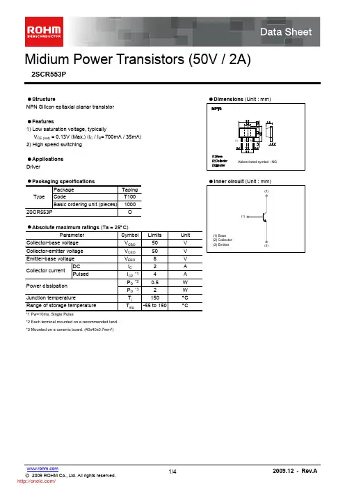
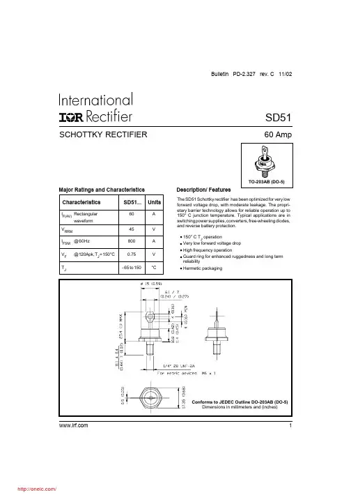
Major Ratings and Characteristics SCHOTTKY RECTIFIER60 AmpSD51Bulletin PD-2.327 rev. C 11/02TO-203AB (DO-5)SD512Bulletin PD-2.327 rev. C 11/02T J Max. Junction Temperature Range -65 to 150°C T stgMax. Storage Temperature Range-65 to 150°C R thJC Max. Thermal Resistance Junction1.0°C/W DC o peration * See Fig. 4to Case R thCS Typical Thermal Resistance, Case to0.25°C/WMounting surface , smooth and greasedHeatsink wt Approximate Weight 15 (0.53)g (oz.)TMounting T orque Min.23 (20)Non-lubricated t hreads Max.46 (40)Case S tyleDO-203AB(DO-5)JEDECKg-cm (Ibf-in)Thermal-Mechanical SpecificationsParametersSD51UnitsConditionsV FMMax. Forward Voltage Drop (2)0.58V @ 35A * See Fig. 10.66V @ 60A 0.86V @ 120A 0.75V @ 120A I RM Max. Reverse Leakage Current (2)50mA T J = 25 °C * See Fig. 2200mA T J = 125 °CC T Max. Junction Capacitance 2900pF V R = 5V DC , (test signal range 100Khz to 1Mhz) 25 °C L STypical Series Inductance7.5nH Measured from top of terminal to mounting planedv/dt Max. Voltage Rate of Change10000V/ µs(Rated V R )V R = rated V RElectrical SpecificationsParametersSD51UnitsConditions(2) Pulse Width < 300µs, Duty Cycle < 2%T J = 150 °C T J = 25 °C I F(AV)Max. Average Forward Current60A 50% duty cycle @ T C = 90°C, rectangular wave form * See Fig. 5I FSMMax. Peak One Cycle Non-Repetitive 800A60Hz half cycle sine wave Surge Current * See Fig. 7or 5ms rectangular pulseParametersSD51 UnitsConditionsAbsolute Maximum RatingsFollowing any rated load condition and with rated V RRM appliedPart numberSD51V RMax. DC Reverse Voltage (V)V RWM Max. Working Peak Reverse Voltage (V)45(1)Voltage Ratings* For Additional Informations and Graphs, Please See the 50HQ Series(1) For SD51 V RWM and V RRM = 45V @ T J = 25°C , =35V @ T J = 150°CSD513Bulletin PD-2.327 rev. C 11/02SD514Bulletin PD-2.327 rev. C 11/024812160102030405060708090A l l o w a b l e C a s e T e m p e r a t u r e - (°C )A v e r a g e F o r w a r d C u r r e n t - I (A )F (A V)5101520253004080120160200A v e r a g e P o w e r L o s s - (W a t t s )F (A V )A v e r a g e F o r w a r d C u r r e n t - I (A )Fig. 5 - Maximum Allovable Case TemperatureVs. Average Forward CurrentFig. 6 - Forward Power Loss Characteristics10100100010100100010000pF S MN o n -R e p e t i t i v e S u r g e C u r r e n t - I (A )S q u a r e W a v e P u l s e D u r a t i o n - t (m i c r o s e c )Fig. 7 - Max. Non-Repetitive Surge CurrentIR WORLD HEADQUARTERS: 233 Kansas St., El Segundo, California 90245, USA Tel: (310) 252-7105TAC Fax: (310) 252-7309Visit us at for sales contact information. 11/02Data and specifications subject to change without notice.This product has been designed for Industrial Level.Qualification Standards can be found on IR's Web site.分销商库存信息: VISHAYSD51。
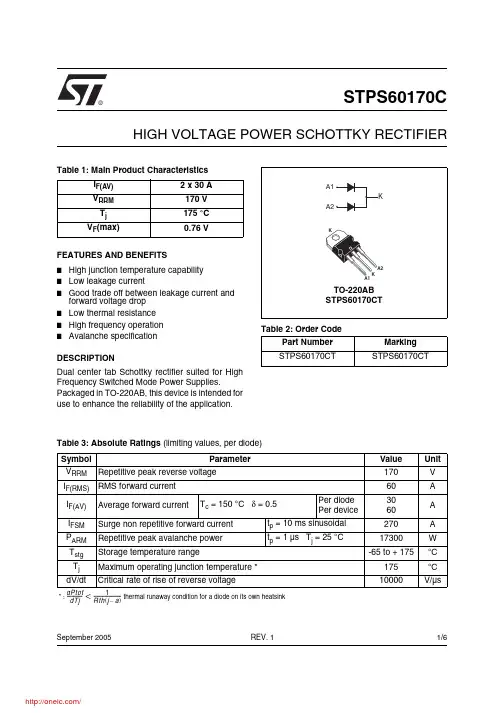
®1/6Table 1: Main Product CharacteristicsI F(AV) 2 x 30 A V RRM 170 V T j 175 °C V F (max)0.76 VSTPS60170CHIGH VOLTAGE POWER SCHOTTKY RECTIFIERREV. 1September 2005FEATURES AND BENEFITS■High junction temperature capability ■Low leakage current■Good trade off between leakage current and forward voltage drop ■Low thermal resistance ■High frequency operation ■Avalanche specificationDESCRIPTIONDual center tab Schottky rectifier suited for High Frequency Switched Mode Power Supplies.Packaged in TO-220AB, this device is intended for use to enhance the reliability of the application.Table 2: Order CodePart Number Marking STPS60170CTSTPS60170CTTable 3: Absolute Ratings (limiting values, per diode)Symbol ParameterValue Unit V RRM Repetitive peak reverse voltage 170V I F(RMS)RMS forward current 60A I F(AV)Average forward currentT c = 150 °C δ = 0.5Per diode Per device3060A I FSM Surge non repetitive forward current t p = 10 ms sinusoidal 270A P ARM Repetitive peak avalanche power t p = 1 µs T j = 25 °C17300W T stg Storage temperature range-65 to + 175°C T j Maximum operating junction temperature *175°C dV/dtCritical rate of rise of reverse voltage10000V/µs* : thermal runaway condition for a diode on its own heatsink dPtot dTj---------------1Rth j a –()-------------------------<STPS60170C2/6Table 4: Thermal Parameters Table 5: Static Electrical Characteristics (per diode)Pulse test:* tp = 5 ms, δ < 2%** tp = 380 µs, δ < 2%To evaluate the conduction losses use the following equation: P = 0.60 x I F(AV) + 0.053 I F 2(RMS)Symbol ParameterValue Unit R th(j-c)Junction to casePer diode Total 1.00.7°C/WR th(c)Coupling0.4When the diodes 1 and 2 are used simultaneously:∆ Tj(diode 1) = P(diode 1) x R th(j-c)(Per diode) + P(diode 2) x R th(c)Symbol ParameterTests conditions Min.Typ Max.Unit I R *Reverse leakage currentT j = 25 °C V R = V RRM35µA T j = 125 °C 835mAV F **Forward voltage dropT j = 25 °CI F = 30 A0.94VT j = 125 °C 0.720.76T j = 25 °C I F = 60 A0.97 1.05T j = 125 °C0.860.92STPS60170C3/6Figure 1: Average forward power dissipation versus average forward current (per diode)Figure 2: Average forward current versus ambient temperature (δ = 0.5, per diode)Figure 3: Normalized avalanche power derating versus pulse durationFigure 4: Normalized avalanche power derating versus junction temperatureFigure 5: Non repetitive surge peak forward current versus overload duration (maximum values, per diode)Figure 6: Relative variation of thermal impedance junction to case versus pulse durationTd =t /Tt pTd =t /Tt ptTd =t /Tt pSTPS60170C4/6Figure 7: Reverse leakage current versus reverse voltage applied (typical values, per diode)Figure 8: Junction capacitance versus reverse voltage applied (typical values, per diode)Figure 9: Forward voltage drop versus forward current (per diode, low level)Figure 10: Forward voltage drop versus forward current (per diode, high level)STPS60170C5/6Figure 11: TO-220AB Package Mechanical DataIn order to meet environmental requirements, ST offers these devices in ECOPACK® packages. Thesepackages have a Lead-free second level interconnect . The category of second level interconnect is marked on the package and on the inner box label, in compliance with JEDEC Standard JESD97. The maximum ratings related to soldering conditions are also marked on the inner box label. ECOPACK is an ST trademark. ECOPACK specifications are available at: .Table 6: Ordering Information■Epoxy meets UL94, V0■Cooling method: by conduction (C)■Recommended torque value: 0.55 Nm.■Maximum torque value: 0.7 Nm.Ordering type Marking Package Weight Base qtyDelivery mode STPS60170CTSTPS60170CTTO-220AB2.20 g50TubeTable 7: Revision HistoryDate RevisionDescription of Changes16-Sep-20051First issue.STPS60170CInformation furnished is believed to be accurate and reliable. However, STMicroelectronics assumes no responsibility for the consequences of use of such information nor for any infringement of patents or other rights of third parties which may result from its use. No license is granted by implication or otherwise under any patent or patent rights of STMicroelectronics. Specifications mentioned in this publication are subject to change without notice. This publication supersedes and replaces all information previously supplied. STMicroelectronics products are not authorized for use as critical components in life support devices or systems without express written approval of STMicroelectronics.The ST logo is a registered trademark of STMicroelectronics.All other names are the property of their respective owners© 2005 STMicroelectronics - All rights reservedSTMicroelectronics group of companiesAustralia - Belgium - Brazil - Canada - China - Czech Republic - Finland - France - Germany - Hong Kong - India - Israel - Italy - Japan - Malaysia - Malta - Morocco - Singapore - Spain - Sweden - Switzerland - United Kingdom - United States of America6/6分销商库存信息: STMSTPS60170CT。