RC系列变频器说明书-中文版[1]
- 格式:pdf
- 大小:1.16 MB
- 文档页数:35
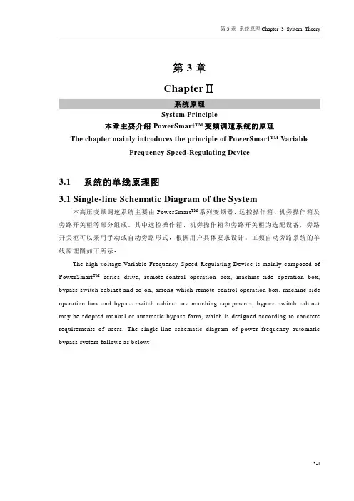
第3章ChapterⅡ系统原理System Principle本章主要介绍PowerSmart TM变频调速系统的原理The chapter mainly introduces the principle of PowerSmart TM VariableFrequency Speed-Regulating Device3.1系统的单线原理图3.1 Single-line Schematic Diagram of the System本高压变频调速系统主要由PowerSmart TM系列变频器、远控操作箱、机旁操作箱及旁路开关柜等部分组成。
其中远控操作箱、机旁操作箱和旁路开关柜为选配设备,旁路开关柜可以采用手动或自动旁路形式,根据用户具体要求设计。
工频自动旁路系统的单线原理图如下所示:The high-voltage Variable Frequency Speed-Regulating Device is mainly composed of PowerSmart TM series drive, remote-control operation box, machine-side operation box, bypass switch cabinet and so on, among which remote-control operation box, machine-side operation box and bypass switch cabinet are matching equipments, bypass switch cabinet may be adopted manual or automatic bypass form, which is designed ac cording to concrete requirements of users. The single-line schematic diagram of power frequency automatic bypass system follows as below:3-13-2图3-1 系统的单线原理图Fig3-1 Single-line Schematic Diagram of the System注:旁路开关柜中KM2、KM3采用高压真空接触器,QF1采用高压真空断路器。
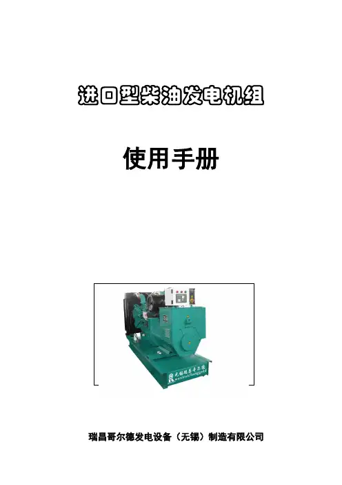
进口型柴油发电机组使用手册瑞昌哥尔德发电设备(无锡)制造有限公司目录目录 11 总体说明 21.1 概述 21.2 机组型号命名 21.3 铭牌 21.4 产品合格证 21.5 安全及提醒 32 发电机组主要部件 32.1 柴油发动机 32.2 交流同步发电机 42.3 机组控制屏 52.4 空气断路器 52.5 其他 53 安装 53.1 安装概述 53.2 存放 63.3 移动 63.4 机房安装74 机组的重要部分及要求12 4.1 冷却系统12 4.2 润滑系统13 4.3 燃油系统13 4.4 控制系统14 4.5 蓄电池17 4.6 配电系统174.7 机组预热器175 运行操作17 5.1 运行前检查17 5.2 普通机组操作和使用18 5.3 自动化机组操作和使用19 5.4 运行之后19 5.5 运行记录195.6 注意事项196 维护保养19 6.1 基本要求19 6.2 发动机20 6.3 发电机21 6.4 控制箱21 6.5 启动电瓶216.6 维护保养记录227 故障查询22-281.总体说明1.1概述瑞昌牌进口型柴油发电机组,作为较为高档的主电源或备用(应急)电源,可广泛地使用在电信、医院、部队、高层楼宇、移动列车、公路建筑、工矿企业、石油勘探等重要场所。
我司根据国际上产品品牌及在国内应用实际情况,本类型产品其配套柴油机选用进口原装或者国内合资企业引进国外技术生产的柴油机,如康明斯柴油机、VOLVO柴油机、帕金斯柴油机、道依茨柴油机等,发电机一般采用斯坦福发电机。
(船用产品也采用马拉松发电机)当然也可以按照用户要求进行合理配置。
机组均可根据用户的具体要求作出不同的配置形式。
如普通型机组、自动化机组、“三遥”智能控制机组、静音型机组、多台并机机组以及移动电站等,并可提供相关的ATS控制屏、并机控制系统等。
1.2机组型号命名Z:自动化型Y:智能型(可以和计算机通信,实现“三遥”)工频柴油发电机组机组额定功率:kW发动机:C—CUMMINS(康明斯)柴油机V—VOLVO(富豪)柴油机D—DEUTZ(道依茨)柴油机P—PERKINS(帕金斯)柴油机DW—DAEWOO(大宇)柴油机1.3安全及提醒●使用及维护机组前,必须阅读并理解本说明书及随机提供的其他文件。
RC-9-4T11G变频器说明书1 .变频器隔厚外壳壳体结构和本安及非本安电路的电气参数,在出厂前均已装配调试合格,用户严禁改动变频器壳体的结构和电气参数,以确保本产品的防爆性能、电气性能和本安性能。
2 .设备在带电情况下,严禁松动隔厚壳紧固件,在检修或处理故障时,请注意“严禁带电开盖"、"断电后2分钟开盖。
3.外壳应接地良好。
4 .接送时请注意输入接统柱标志R、S、T(电源)和输出接统柱标志U、V、W (电机),不得接错。
U、V、W端子一旦接入电源会造成变频器严重损坏。
5 .在变频器防爆主腔内进行操作时,手上必须带接地导统或静电环。
6 .变频器电源R、S、T停电以后2汾钟内禁止对变频器隔厚主腔内的任意电路进行操作,用仪表确认电容放电完毕,方可实施主腔内作业。
7.负载运行过程中尽量避免瞬时停电。
8 .禁止对变频器主回路及控制回路进行耐压试验,如对与变频器有电路联系的相关设备进行耐压试验之前应将与变频相关的电路断开。
9 .测量变频器输出电压时必须使用整流或交流电压表,使用其它一般电压表或数字式电压表测量高频脉冲电压时,容易因显示不准确而产生误操作。
10 .变频器与电机间最大距离应在5米以内,接线最好敷设于金属管内,为防止干扰,输出电缆最好选用屏蔽电缆。
11 .两次启动时间间隔不能小于5分钟,一小时内启动次数不大于10。
12.使用中应尽可能避开有淋水的地方,在井下断掉电源一段时间后重新使用之前,请打开防爆主腔确认内部是否有潮湿积露存在,如发现潮湿积露需采取除湿措施后方可使用。
13.变频器的输出相序不受输入相序的影响,改变输入相序并不能改变变频部分的相序输出。
在变频系统的输入供电改变时,应对变频器的工频、变顷状态下电机的转向进行测试,以防事故发生。
14.任何故障发生后,必须保证在已停止状态,复位才有效。
15.安装使用中不得随意改变本说明书中的配接设备。

RC500-4T0150GB变频器说明书我们从包装箱里取出这个变频器,检查变频器机身侧面的型号铭牌,确认变翎器型号、产品是否与定货单相符,机器是否有损坏。
1、观察这个变频器的铭牌,并从铭牌中理解变频器的命名规则,从命名规则中可以知道,这个型号是XX,功率是2.2KW,输入是AC 380V加百分之15、5.8A,输出是AC380V、0 400Hz、5.0A。
2、变颇器上面的操作面板可以单独取下来,XX变绷器的操作面板,用于变颇器参数设置的主要界面,进行操作面板的拆卸时,先按住操作面板上端侧面的擂销,把操作面板往前拉出后卸下,进行操作面板安装时,顺序步骤相反。
3、进行变报器前盖板的拆卸,对前盖板取下时,先旋松安装前益板用的固定螺丝,再将盖板拨出。
4、拆卸完前盖板后,进行主电路接线,其中R、S、T是电源进线,U、V、W是出线,接电动机,注惫为保证电气安全,必须进行可靠接地。
5、在第一次简单接线中,必须注意:
电源及电机接线的压着端子,需要使用带有绝缘套管的端子
电源一定不能接到变频器的输出端上U,V,W,否则将损坏变频器
接线后,零碎线头必须清除干净。
零碎线头可能造成设备异常、失灵和故障,必须始终保持变频器清沽。
为使线路压降在百分之2以内,需要用适当型号的电线接线。
变颇器和电动机间的接线距离较长时,特别是低频率输出情况下,会由于主电路电缆的线路下降,而导致电动机的转矩下降。
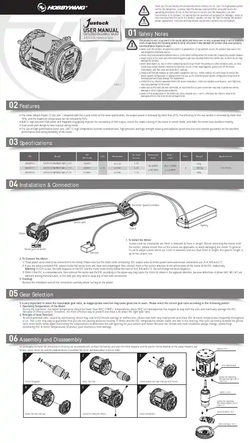
Safety Notes0102Features05Gear Selection06Assembly and Disassembly03SpecificationsIt is very important to select the reasonable gear ratio, as inappropriate selection may cause great loss to users. Please select the correct gear ratio according to the following points!1. Operating Temperature of the MotorDuring the operation, the motor temperature should be lower than 90℃ (194℉). Temperatures above 90℃ will demagnetize the magnet & may melt the coils and eventually damage the ESC (because of strong current). Therefore, the most effective way to prevent over-heat is to select the right gear ratio. 2. Principle of Gear SelectionTo avoid potential risks, caused by overheating, which may lead to ESC/motor damage or malfunction, please start with very small pinion and check ESC & motor temperatures frequently throughout a run. This is the only way to guarantee that you are not causing excessive heating. If Motor and the ESC temperatures remain stable and low in the running, then you can slowly increase the pinion (with more teeth) while again monitoring the temperatures to determine the safe gearing for your vehicle and motor. Because the climate and track conditions always change, please keep monitoring ESC & motor temperatures to protect your electronics from damage.For prolonging the motor life and raising its efficiency, we recommend users to check the bearing, and clean the motor regularly; and the specific interval depends on the usage frequency and terrains. Please follow the assembly diagram below to assemble the motor, and disassemble in reverse order.USER MANUALJUSTOCK Handout SpecSensored Brushless Motor• The motor adopts 4-pole 12 slot core. Compared with the 2-pole motor of the same specification, the output power is increased by more than 25%, the efficiency of the rear section is increased by more than 10%, and the maximum temperature can be reduced by 50%.• Built in high-precision Hall sensor and magnetic ring greatly improve the consistency of Hall output, ensure the stable running of the motor in sensor mode, and make the motor have excellent linearity.• Dual sensor port design to meet various wiring needs.• The use of high-performance stator core, 200 ° C high temperature resistant enameled wire, high-precision and high-strength bearing and explosion-proof structure rotor provide guarantee for the excellent performance and lasting durability of the motor.This product is NOT a toy and it is for use by adults and teens over 14 only, so please keep it out of children’s reach. Please keep the following points in mind; otherwise it may damage the product and cause property loss and physical injuries to users.• Never leave this product unsupervised when it is powered on. If any problem occurs, the product may cause a fire and jeopardize peripheral devices.• Please check wire sequences between the ESC & the motor carefully before the connection, to avoid any possible mistakes. damage or other unpredictable problems.• Never let the temperature of the motor can (shell) exceeds 90°C (194°F), otherwise the motor is likely to be damaged and (or) the rotor will be demagnetized.04Installation & Connection3. CheckupRecheck the installation and all the connections carefully before turning on the power.Stator x 1PCSPCB outlet boardScrews for fastening the rear end cap x 3PCS ( M2 x 4 )Rotor x 1PCSScrews for fastening the Sensor Board x 2PCS ( M2 × 3 )Sensor board x 1PCSRear end cap x 1PCS。
RC3可编程步进电机控制器一.概述RC3可编程步进电机控制器是我厂采用新型的进口元件开发出的自动化控制设备,它可与步进电机驱动器、步进电机组成一个应用广泛的步进电机控制系统,能控制多台步进电机多段分时运行。
它广泛应用于各种工业控制场合。
按键采用轻触式开关按键,手感好,可靠性高,使用寿命长,面板上的按键有相对应得功能说明。
本控制器采用计算机式的编程语言,拥有输入、输出、计数、循环、条件转移、无条件转移、中断等多种指令,只需在控制器上按键选择指令和输入参数即可完成程序编程来控制电机运转和信号的输出以及被外部输入信号所控制,具有编程灵活、适应范围广等特点。
二.技术指标●可控制3台步进电机(任意两台电机同时工作)●可编250段程序指令(不同的工作状态)●9条升降速曲线供选择●脉冲最高输出频率:40KHz●8个输入,6个输出(一个继电器--10A触点,五个晶体管---1A,可直接驱动电磁阀)数码显示,可显示当前运行的指令名、计数次数、脉冲数●采用共阳接法,+5V输出,可直接驱动我厂的RC系列步进电机驱动器三.控制器的面板说明1.面板示意图2. 面板说明:12位数码显示:显示程序名,参数值,以及各种运行状态。
红绿指示灯:显示输入、输出、方向、脉冲等的工作状态。
操作键:多为复合键,在不同的状态下起不同的作用。
3.接线说明:具体接线可参考后面的完整流程。
(1)OPTO、DIR、PUL:步进电机驱动器控制线,采用共阳接线方式其中:OPTO 所有驱动器的公共阳端DIR1 0号电机方向电平信号PUL1 0号电机脉冲信号DIR2 1号电机方向电平信号PUL2 1号电机脉冲信号DIR3 2号电机方向电平信号PUL3 2号电机脉冲信号(2) 启动端,相当于面板上启动键。
(3)停止:等信号端,相当于面板上的停止键,再次按启动键后,程序继续运行。
停止端接线方式与启动端的接线方式一致。
(4)输入:通用开关量输入端(见开关量输入电路图)。
手册引导内容提要23.介绍24.手册结构25.补充文件26.操作手册使用人群27.手册中使用的信号和警示28.使用的方式和缩写29.版本附件30.设备描述31.目的32.潜在的危险33.总述34.电源35.外加24VDC36.使用的电缆型号37.安全须知38.Congrav RC-4使用安全须知39.安装安全须知40.接线安全须知41.使用和操作安全须知42.硬件描述43.Congrav RC—4:类型44.Congrav RC—4A:显示和按键45.集成按键及其功能46.显示和功能组成47.参数更改48.数字输入49.固定参数设置的选择50.如果…。
,更改参数不被接受51.Congrav RC—4B:52.Congrav RC-4的插卡槽53.现场的可能连线54.Congrav RC-4的基本功能55.插入卡RC4—MSIO56.XS1.1:与主计算机的连接57.XS1。
2:与ISC现场总线的连接58.XS1.3:与调试解调器和工控电脑的连接59.Congrav RC—4的选项卡60.CDIO插入卡61.DIOP插入卡62.输入输出模式-数字式RC-4的终端功能63.ANOP插入卡64.输入输出模式-模拟式RC—4的终端功能65.Profibus模式66.调试67.安装68.调试,Congrav RC—4的开机69.Congrav RC-4:软件升级70.ISC—CM:软件升级71.菜单页F100安装结构72.F110:安装模式73.模拟结构74.F120:主计算机操作75.F130:显示内容改变76.连锁停机77.时间和日期78.F150:配方处理79.设定值斜线,设定值阈值80.调试操作81.F200:打印机结构,内存值重设82.打印功能83.F210:如何清除记忆内容84.F300:设定值输入和选择85.安装设定值86.加料器设定值87.`设定值的模拟控制88.设定值斜线,设定值阈值(菜单页F150)89.选项90.F310:滞后时间91.报警停机92.F400:安装的实际值,总产量重设93.F430:总产量重设94.单台加料器操作95.加料器页的抬头96.Kxx0:加料器控制97.操作功能98.开机5499.停机54100.报警重设101.补料55102.删除55103.开始试样104.开始去皮105.右侧行实际值的显示106.Kxx1:产品参数107.自动去皮108.检查最大输出109.堆积密度110.体积最大输出111.十进制转换112.十进制转换的设置113.模式59114.失重式加料(GF)115.体积式控制(VR)116.体积式设置(VS)117.排料(DI)118.检查最大输出(CM)119.重量式排料(GD)120.体积式加料(VF)121.测量(M)122.运行过程中GF和VF模式转换123.Kxx2:控制参数124.PID控制的设置125.控制成套配合126.重量式计算最大输出127.CM值的存储128.F500:报警报告和开机条件129.报警报告130.缺省的开机条件131.系列驱动控制操作的错误代码132.系列变频器133.振动放大器控制器ISC—VC134.Kxx5:报警结构135.硬件结构12.1 Kxx8:ISC-CM(-A)的硬件结构12。
手册引导内容提要1介绍1.1手册结构1.2补充文件1.3操作手册使用人群1.4手册中使用的信号和警示1.5使用的方式和缩写1.6版本附件2设备描述2.1目的2.2潜在的危险3总述3.1电源3.2外加24VDC3.3使用的电缆型号3.4安全须知3.4.1Congrav RC-4使用安全须知3.4.2安装安全须知3.4.3接线安全须知3.4.4使用和操作安全须知4硬件描述4.1Congrav RC-4:类型4.2Congrav RC-4A:显示和按键4.2.1集成按键及其功能4.2.2显示和功能组成4.3参数更改4.3.1数字输入4.3.2固定参数设置的选择4.3.3如果….,更改参数不被接受4.4Congrav RC-4B:4.5Congrav RC-4的插卡槽4.5.1现场的可能连线4.6Congrav RC-4的基本功能4.6.1插入卡RC4-MSIO4.6.1.1XS1.1:与主计算机的连接4.6.1.2XS1.2:与ISC现场总线的连接4.6.1.3XS1.3:与调试解调器和工控电脑的连接4.7Congrav RC-4的选项卡4.7.1CDIO插入卡4.7.2DIOP插入卡4.7.2.1输入输出模式-数字式RC-4的终端功能4.7.3ANOP插入卡4.7.3.1输入输出模式-模拟式RC-4的终端功能4.7.4Profibus模式5调试5.1安装5.2调试,Congrav RC-4的开机5.3Congrav RC-4:软件升级5.4ISC-CM:软件升级6菜单页F100安装结构6.1F110:安装模式6.2模拟结构6.3F120:主计算机操作6.4F130:显示内容改变6.5连锁停机6.6时间和日期6.7F150:配方处理6.7.1设定值斜线,设定值阈值6.7.2调试操作7F200:打印机结构,内存值重设7.1打印功能7.2F210:如何清除记忆内容8F300:设定值输入和选择8.1安装设定值8.2加料器设定值8.2.1`设定值的模拟控制8.2.2设定值斜线,设定值阈值(菜单页F150)8.3选项8.4F310:滞后时间8.5报警停机9F400:安装的实际值,总产量重设9.1F430:总产量重设10单台加料器操作10.1加料器页的抬头10.2Kxx0:加料器控制10.3操作功能10.3.1开机5410.3.2停机5410.3.3报警重设10.3.4补料5510.3.5删除5510.3.6开始试样10.3.7开始去皮10.3.8右侧行实际值的显示10.4Kxx1:产品参数10.4.1自动去皮10.4.2检查最大输出10.4.3堆积密度10.4.4体积最大输出10.4.5十进制转换10.4.5.1十进制转换的设置10.4.6模式5910.4.6.1失重式加料(GF)10.4.6.2体积式控制(VR)10.4.6.3体积式设置(VS)10.4.6.4排料(DI)10.4.6.5检查最大输出(CM)10.4.6.6重量式排料(GD)10.4.6.7体积式加料(VF)10.4.6.8测量(M)10.4.6.9运行过程中GF和VF模式转换10.5Kxx2:控制参数10.5.1PID控制的设置10.5.1.1控制成套配合10.5.1.2重量式计算最大输出10.5.1.2.1CM值的存储11F500:报警报告和开机条件11.1报警报告11.2缺省的开机条件11.3系列驱动控制操作的错误代码11.3.1系列变频器11.3.2振动放大器控制器ISC-VC 11.4Kxx5:报警结构12硬件结构12.1 Kxx8:ISC-CM(-A)的硬件结构12.1.1 速度输入12.1.2 传感器(重量读取)的结构12.1.3 驱动控制器12.1.4 ISC-CM-A模拟输入输出的结构12.1.4.1 ISC-CM-A上单台控制的选项12.1.4.2 Kxx8:模拟输入12.1.4.3 Kxx8:模拟输出12.2 ANOP模拟输入输出的结构12.2.1 安装控制和安装的实际值12.2.1.1 菜单页F190的参数12.2.2 ANOP的组分功能12.2.2.1 模拟输入:模拟单台控制12.2.2.2 模拟输出:总操纵量或实际值12.2.2.2.1 模拟输出信号范围的定义12.3 CDIO的数字输入输出12.4 DIOP的数字输入输出12.4.1 DIOP:功能描述12.5 ISC现场总线机构12.5.1 如果构建总线通讯12.5.2 总线通讯的关闭12.6 调试解调器的机构12.7 主计算机操作机构12.7.1 MISO卡上的主计算机接口12.7.2 Profibus DP操作结构12.7.3 以太网接口的结构13校正程序13.1加料器参数13.2加料器参数功能解释13.2.1CP02-加料范围13.2.2CP04-欠载13.2.3CP03-最大输出量13.2.4CP05-过载13.2.5CP06-粗去皮13.2.6CP07-平均重量取数13.2.7CP08-总产量累计分值13.2.8CP09-最小速度13.2.9CP010-最大速度13.2.10CP11-控制偏差13.2.11CP12-报警停机滞后时间13.2.12CP13-联锁类型13.2.13CP14-实际值指示13.2.14CP15-杠杆臂值13.2.15CP16-料斗内容13.2.16CP17-最小补料料位13.2.17CP18-最大补料料位13.2.18CP19-Window/K1/滤波IDL/F, AED 13.2.19CP20-数字速度13.2.19.1标准速度监控13.2.19.2FlexWall-Plus加料器的运动监控13.2.19.3数字式速度取数13.2.19.4推荐输入13.2.20CP21-最大补料时间13.2.21CP22-补料优化13.2.22CP23-稳定时间13.2.23CP24-测样时间13.2.24CP25-防振(A V)切断时间13.2.25CP26-PID控制器接近时间13.2.26CP27-控制器自动化13.2.26.1控制器自动化13.2.26.2开机自动化13.2.26.2.1重复的开机自动化13.2.26.2.2总体开机自动化13.2.27CP28-滤波限制13.2.28CP29-实际值的接纳13.2.29CP30-总操纵量的接纳13.2.30CP31-体积控制(VR)实际值的接纳13.2.31CP32-开机滞后时间13.2.32CP33-称重桥(LWB)的长度13.2.33CP34-重量测试值(WTV)13.2.34CP35-摄取(AP)13.2.35CP36-自动去皮范围13.2.36CP37-无负载时间自动去皮13.2.37CP38-有比例的皮带速度13.2.38CP39-皮带长度13.2.39CP40-dead time way13.3附加参数13.3.1AP01-05 校正13.3.2AP11-可用的称重范围13.3.3AP12-drop out13.3.4AP13-速度模式13.3.5AP14-滑动影响13.3.6AP15-滑动值13.3.7AP16-速度接纳性13.3.8AP17-无负载时间13.3.9AP18-AT时间13.3.10AP19-驱动控制2最小13.3.11AP20-驱动控制2最大14硬件测试功能14.1F140:输入输出测试-外围(安装)14.2Kxx3:输入输出状态显示-外围14.3Kxx4:测试功能和模拟14.3.1模拟模式14.3.2输入输出测试(加料器)15名词解释附件11915.1技术数据15.2电磁兼容性15.3零配件清单15.4可能显示的模式清单15.5菜单页清单插图表图4-1:Congrav RC-4后部视图图4-2:Congrav RC-4后部视图(带ProfiBus模式)1 总介绍1.1手册的结构现有的操作手册包括:RC-4的:●技术操作和●RC-4 HGC软件(其版本请参见封页)按照下列顺序,每章独立描述一个完整的主题:●设备的描述●使用特性●硬件执行●硬件功能定义●操作●软件描述●参数描述和●结构例举1.2附加文件●ISC系统的描述●ISC-CM,ISC-FC和ISC-VC的技术手册●相应主计算机程序手册1.3操作手册所适用的人群操作手册适用于以下两组人群:●经过授权和培训过的专业技术人员来进行安装和其它电气工作。
ABI EDCFGHRC-4BiRC-7BiRC-1260BiInstructionManualRC-7BI MODEL SHOWN(The RC-4Bi has a 20-minute pause position between station #4 and "REST.") DESCRIPTION OF CONTROLS Refer to Figure 1A. HOUR DIAL with 23 CYCLE START PINS: The HOUR dial contains 23 pins for scheduling automatic "Starts" on any hour (except midnight—which is day changeover time). Embossed characters provide quick identification for each hour, AM or PM, noon and midnight. Captive type pins are designed for simple push-pull operation.B. DAY DIAL with 14 SCHEDULING PINS: The calendar DAY dial contains 14 cap-tive pins for scheduling irrigation everyday or any day within a two week range. Each pin represents a 24 hour period beginning at midnight. Embossed characters are on the dial, adjacent to each day of the week.C. STATION SELECTOR/INDICATOR DIAL: The STATION selector/indicator dial contains the timing controls (D) for each of the stations. The dial automatically rotates during a watering cycle with the current station appearing at the top, under the station pointer. REST indicates the system is off and no watering is taking place. The dial is also used for manual selection of any station for semi-automatic operation.Figure 1Save an extra 15% o new sprinkler timers andirrigation controllers at the Rain Bird Online Store.*Enter discount code:UPGRADE15at checkout to save an extra 15% o ** Additional discount not valid on clearance items, bundles or store specials. Discount applies to controller products only. Cannot be combined with other store discount codes. Valid at the Rain Bird Online Store only.Subject to change without notice.Still struggling with your old sprinkler timer? Having a hard time complying with local watering restrictions?Upgrading to a new Rain Bird sprinkler timer is easier than you might think.New timers are easier to program than ever before, with powerful features to help save you time and water while keeping your yard healthy and vibrant. There are lots of models to meet your needs, including indoor and outdoor versions, exible modular timers and even smart controllers thatautomatically adjust themselves based on the weather.Shop Now at andenjoy exclusive upgrade savings!Valve Output WiringThe controller transformer provides 24 VAC output for the station valves. The output leads are color coded and stamped with the corresponding station designations.(See Figure 3.)1. Connect one Lead from each valve to the desired sta-tion output lead using wire nuts.NOTE: If the Master Valve/Pump Start circuit is used,connect only one Rain Bird, 2 watt, solenoid valve per station.2. Connect the second lead from all valves to the white common output lead. Record the valve locations or land-scape zone identification for each station on the label in-side the cabinet door.Master Valve Wiring1. Connect one lead from a 24 VAC Master Valve to the controller Master Valve lead (Wht/Orn).2. Connect the other Master Valve lead to the controller common (white) along with the valve common leads.CAUTION: If a master valve is not being used, be sure to tape the end of the Master Valve lead to prevent any possibility of "shorting."OUTPUT LEAD COLOR CODE Station 1:Brown 2:Red 3:Orange 4:Yellow 5:Green 6:Blue 7:Violet 8:Gray 9:White 10:White/Blk 11:White/Bm 12:White/Red Master Valve:Wht/Orn Valve Common:White (2) Transformer:Wht/RedWht/Red w/ “line input” label Wht/Brn w/ “line input” labelFigure 3MOUNTING1. Choose a location that provides a minimum clearance of 13" wide x 8" high. Since the electrical connections are provided at the bottom of the cabinet, clearance should be allowed for the conduit connections etc. Refer to Figure2. The location must be within 5 feet of an electrical outlet.2. Remove the 4 panel mounting screws, and carefully lift out the panel.3. Position the cabinet on the wall at the mounting location, and with a pencil, mark the mounting holes desired (4 holes are provided) on the wall. Two vertical holes are provided for mounting to a wall stud. (Note: Use #10 screws).ELECTRICAL CONNECTIONSALL WIRING MUST BE INSTALLED AND CONNECTED IN ACCORDANCE WITH LOCAL CODES. A basic wiring diagram, with color code identification is provided on the inside surface of the cabinet for easy reference.A 1/4" dia. hole is provided in the bottom of the cabinet for insertion of the transformer input wire. See Figure 4.Prior to plugging the transformer into a 120 VACwall receptacle, insert the wire through the 1/4"hole in the lower left corner of the controller, tie an overhand knot in the wire about 5" from the end (inside the case). This will prevent inadver-tent disconnection of the wire. Connect one or-ange wire to the wht/red wire with the "line in-put" label and connect the other orange wire to the wht/brn wire with the "line input" label. (See Figure 4)Now, plug transformer into wall receptacle.(Note: International transformer is not "plug-in"type.)Instructions for Attaching Plug-In Transformer.Electrical System Checkout1. Rotate the STATION dial counterclockwise to position REST at the top directly un-der the Station pointer.2. Pull all pins on the HOUR and DAY dials to the "out" position.3. Put the MODE switch in the AUTO position.4. Make sure transformer is plugged into a wall receptacle.5. Adjust each station TIME control to the 5 minute mark. (See Figure6.)6. Rotate the STATION dial (counterclockwise) to position Station 1 under the pointer.Watering should commence shortly as the automatic mechanism latches with the Sta-tion dial.The 5-minute interval should provide sufficient time to observe control valve operation.If more time is required, simply adjust the timing knobs as necessary. The controller will advance through each station, in sequence, providing opportunity to observe each circuit for proper operation.Upon satisfactory checkout of the system, proceed to adjust the controller clock.SETTING THE CONTROLLERWith the main power ON, proceed to adjust the clock for the correct time and day.1. Put the MODE switch in the OFF position.2. Rotate the HOUR dial (clockwise only) to position the current time opposite theTIME pointer at the top of the panel. Observe the dial for the correct AM or PM numer-als.ATTACHING TRANSFORMER TOCONTRLLERFigure 4position the dial such that the TIMEpointer will point midway between the 1and 2 numerals on the PM side of thedial. If a more precise adjustment is de-sired, the best procedure would be topush-in the pin corresponding to the up-coming hour (in this example, the 2 PMpin) and on that hour, slowly rotate thedial until you hear the "click" of themicro-switch.3. Proceed to set the present day by ro-tating the calendar DAY dial to positionthe correct letter opposite the DAYpointer at the bottom of the dial.4. Next, rotate the STATION dial in acounterclockwise direction to positionREST at the top under the STATIONpointer. This completes the controllerclock setting.SCHEDULING AUTOMATIC OPERATIONMake sure the HOUR and DAY dials are set to the correct time and that all pins are in the "out" position.1. Push in the pin(s) corresponding to the day(s) on which watering is desired. Re-member, each DAY pin represents a 24 hour period beginning at midnight.2. Next, select the desired starting time(s) and push in the corresponding pin(s) on theHOUR dial.3. The first mark (square dot on the station dial) is the minimum time setting and rep-resents approximately 3 minutes. The small white arrow moves with the knob for visual indication of each setting. (There will be no valve output when the arrow is positioned between "off" and the "square dot.'') The ratchet notches represent 1 minute incre-ments for precise settings. The OFF position at each timing dial, omits the station fromthe schedule.quired to prevent a second start within a givenhour is 20 minutes. Conversely, the maximumaccumulated time to permit a cycle start on aconsecutive hour is 55 minutes. Total cycle timeof more than one hour is permissible.NOTE:It takes about 20 minutes for the hourdial pin that started a watering cycle to move offthe cycle-start switch behind the face panel. Tomake sure the RC-4Bi will not start another cy-cle when the combined running time of stations1 through 4 is less than 20 minutes, the con-troller will stop at the non-existent station #6 po-sition and time out 20 minutes before returningto "REST."This completes the automatic setting of the con-troller. Move the MODE switch to the AUTO po-sition. The controller will now automatically con-trol the landscape irrigation according to theSEMI-AUTOMATIC OPERATIONThe controller may be operated at any time in a semi-automatic mode simply by turn-ing the STATION dial counterclockwise to position the desired station at the top, justahead of the Station pointer. Allow the automatic mechanism to advance into the de-sired timing zone. The selected station will operate for the time set on the dial, afterwhich, the remaining stations will follow in sequence until the REST position again ap-pears under the Station pointer.RAIN SHUTDOWNThere may be occasions where it is desired to interrupt all landscape irrigation. Condi-tions such as rainy weather, system repair, landscape renovation, or other excavationwork. The temporary shutdown of the system is accomplished by moving the MODEswitch to the OFF position. This eliminates controller output to the valves without inter-rupting the controller timing circuitry. The controller will not operate either automati-cally or semi-automatically. A summary of the operating instructions is provided on thelabel inside the controller door.MAINTENANCEThe controller is designed to provide years of trouble-free service. The controller re-quires no preventative maintenance or lubrication. Should trouble occur, refer to theTroubleshooting chart for possible remedies, or contact your local authorized RainBird dealer.TROUBLESHOOTING CHARTDIFFICULTYPOSSIBLE CAUSEREMEDYClock stopped.a. Blown fusea. Replace fuse. If controller stops again, check system circuits to locate trouble.b.No power to controller. b. Check line voltage andconnections at each end.c. In the RC-4Bi, the station dial may be in the 20-minute pause position between sta-tion 4 and rest.c. Let controller time out for 20-minutes and return to "REST" automatically.DAY and HOUR dials function incorrectly.a. Clock set for incorrecttime.b. Pins incorrectly set.a. Reset clock for the "present" time.b. Check pin settings and "accumulated cycle time on station dial.DAY and HOUR dials function, but cycle will not start automatically.a. MODE switch in wrong po-sition. a. Move switch to AUTO po-sition.Controller recycles imme-diately without stopping in the REST position. a. Insufficient cycle time al-lowed.b. Total cycle time coincideswith a succeeding START pin.a. Adjust cycle time for morethan 15 minutes.b. Reset the HOUR pins or readjust the accumulated cycle time.Some stations do not op-erate.a. Station time set at OFF.b. Faulty valve wiring. a. Set TIME control for more than 3 minutes.b. Check connections be-tween controller and valves.Also, check valve actuators.Station dial does not stop at a "Timed" stationa. Insufficient time set on dial.a. Adjust the TIME control for more than 3 minutes.Should trouble be isolated in the controller mechanism, remove the entire panel as-sembly from the cabinet and return to your local distributor for repair.THANK YOU for your expression of confidence in Rain Bird Sprinkler Mfg. Corp. As the world's leading manufacturer of irrigation systems and components, our efforts are directed to providing you with the finest quality products and components available today.Your new Controller has been designed using proven technology. You will find it simple to use. We are confident that you will enjoy many years of reliable, trouble-free operation. This manual describes the Controller's functions in detail. We invite you to read it thoroughly so that you may use your Controller to its maximum capability.Again, thank you for providing Rain Bird with the opportunity to meet your irrigation needs.Customer Support Center6640 S. Bonney Ave. Tucson, AZ 857061-800-RAIN-BIRD。
面板式调速器菜单菜单操作:参数Pr09正转启动加速时间(0-9999)*0.1秒1.0S Pr10正转停止方式 1.自由停机2.减速停机2Pr11正转停机减速时间(0-9999)*0.1秒Pr10选择2时,菜单有效1.0S Pr12反转起动加速时间(0-9999)*0.1秒 1.0S Pr13反转停止方式 1.自由停止2.缓慢停止2Pr14反转停机减速时间(0-9999)*0.1秒Pr13选择2时,菜单有效。
1.0S Pr15堵转保护时间0-9999毫秒5000m s Pr16堵转保护转速百分比0%~100%:堵转判断值0:关闭堵转保护功能10Pr17第一段速0RPM-3000RPM 500RP M Pr18第二段速0RPM-3000RPM 700RP M Pr19第三段速0RPM-3000RPM 900RP M Pr20键盘设定转速0RPM-3000RPM 900RPMPr21个位:设定转速低于最低转速动作十位:电网频率选择个位:0停止运行,1以最低转速运行;十位:0-50Hz,1-60Hz 0Pr22速度调节增益Kp 10~30080Pr23速度调节积分Ki 10~30040Pr24电机控制模式选择0:闭环控制1:开环控制0Pr25位置控制正转行程0~9999mm(若时间*0.1S)0Pr26位置控制反转行程0~9999mm(若时间*0.1S)0Pr28菜单延迟退出时间5S~60S 10S Pr29恢复出厂设置 1.不恢复2.恢复出厂设置1Pr30程序版本软件版本号****Pr33反转速度0~3000RPM 0Pr34堵转保护次数0~9999****Pr35端子开关滤波时间0~9999(单位*2ms)10Pr36丝杆螺距或齿条行程0~9999(单位0.1mm)0Pr37位置控制最大行程0~9999mm 520Pr38自动模式正转后停机时间0-9999(单位*0.1S)0Pr39自动模式反转后停机时间0-9999(单位*0.1S)0若自由停机电机停止较快,可选择减速停机,改变Pr11设定值,可改变缓慢减速停止的快慢时间设置大,电机起动平缓起动时间长时间设置小,电机起动快猛起动时间短若自由停机电机停止较快,可选择减速停机,改变Pr14设定值,可改变缓慢减速停止的快慢“0”,反转速度和正转速度一致不为0,反转速度通过Pr33单独给定用于监控发生堵转保护的次数位置控制模式:一个方向运行到达设定行程自动换向运行;时间控制模式:一个方向运行到达设定时间自动换向运行;时间设置大,电机起动平缓,起动时间长,时间设置小,电机起动快猛,起动时间短。
RC500变频器说明书一、简介变频器是由计算机控制电力电子器件,将工频交流电变为频率和电压可调的三相交流电的电器设备,用以驱动交流异步(同步)电动机进行变频调速。
变频器的出现,使交流电动机的调速变得和直流电动机一样方便,并可由计算机联网控制,因此,得到了广泛的应用,其发展前景广阔。
表1变频调速的效果由三相异步电动机转子转速公式:n=(1-s)60f1/p,三相异步电动机的`调速方式有:变频(f1)调速、变极(p)调速和变转差率(s)调速。
变频器的调频调压原理:1.调频原理2.调压原理综上所述,变频器的调频调压过程是通过控制三相调制信号进行的。
二、变频器的组成变频器是由计算机控制大功率开关器件将工频交流电变为频率和电压可调的三相交流电的电器设备。
由主电路和控制电路两大部分组成,主电路包括整流及滤波电路、逆变电路、制动电阻和制动单元,控制电路包括计算机控制系统、键盘与显示、内部接口及信号检测与传递、供电电源和外接控制端子等。
三、变频器的分类1.按变换环节分为,交-直-交型和交-交型两种。
2.按改变变频器输出电压的方法分为,PAM调制和P注意不要安装移相电容噪声滤波器(选件FR-BIF)或浪涌吸收器到变频器的输出侧请正确连接输出侧(端子U,V,W)与电机之间电缆这将影响电机的旋转方向(3)试运行注意请在运行前确认调整各参数机械有可能发生意想不到的动作400V级1.5K 3.7K在负荷GD2小的情况输出频率在20Hz 30Hz 范围内少量的旋转误差有可能增加此时请设定Pr.72"PWM频率选择"为6kHz以上请确认没有噪音或漏电流等的影响A-2。