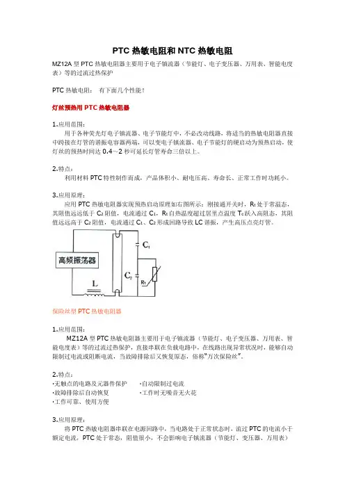
PTC_PT2314_4
- 格式:pdf
- 大小:427.14 KB
- 文档页数:20
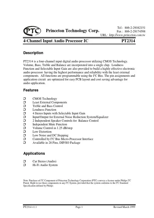
4-Channel Input Audio Processor PT2314 DESCRIPTIONPT2314 is a four-channel input digital audio processor utilizing CMOS Technology. Volume, Bass, Treble and Balance are incorporated into a single chip. Loudness Function and Selectable Input Gain are also provided to build a highly effective electronic audio processor having the highest performance and reliability with the least external components. All functions are programmable using the I2C Bus. The pin assignments and application circuit are optimized for easy PCB layout and cost saving advantage for audio application.FEATURES• CMOS Technology•Least External Components•Treble and Bass Control•Loudness Function• 4 Stereo Inputs with Selectable Input Gain•Input/Output for External Noise Reduction System/Equalizer• 2 Independent Speaker Controls for Balance Control•Independent Mute Function•Volume Control in 1.25 dB/step• Low Distortion•Low Noise and DC Stepping•Controlled by I2C Bus Micro-Processor Interface•Available in 28 Pins, DIP or SOPAPPLICATIONS•Car Stereo (Audio)•Hi-Fi Audio SystemNote: Purchase of I2C Component of Princeton Technology Corporation (PTC) conveys a license under Philips I2C Patent Right to use these components in any I2C System, provided that the system conforms to the I2C Standard Specification defined by Philips4-Channel Input Audio Processor PT2314BLOCK DIAGRAMLIN1LIN2LIN3LIN4LIN1LIN2LIN3LIN4RIN1RIN1Input Selector&Gain ControlT R E B L E _RSupplyVolume &LoudnessVolume &LoudnessBass BassTrebleTrebleRBRBSerial Bus Decoder & LatchesT R E B L E _LL O U TMuteMuteSpeaker ATTSpeaker ATTOUT_LDGNDOUT_RL I NL O U D _LB O U T _LB I N _L CLK DATA V D DA G N DR E FR O U TR I NL O U D _RB O U T _RB I N _RRIN2RIN3RIN4RIN4RIN3RIN24-Channel Input Audio Processor PT2314 PIN CONFIGURATION1 2 3 4 5 6 7 8 9 10 11 12 13 142827262524232221201918171615 PT2314VDDAGND TREB_L TREB_RRINRO UT LO UD_RRIN4RIN3RIN2RIN1 LO UD_LLIN4LIN3REF CLK DATA DG ND OUT_L OUT_R BOUT_R BIN_R BOUT_L BIN_L LO UT LINLIN1LIN24-Channel Input Audio Processor PT2314 PIN DESCRIPTIONPin Name I/O Description Pin No.VDD - Supply Input Voltage 1Ground 2AnalogAGND -TREB_L I Left Channel Input for Treble Controller 3TREB_R I Right Channel Input for Treble Control 4 RIN I Audio Processor Right Channel Input 5ROUT O Gain Output and Input Selector for Right Channel 6LOUD_R I Right Channel Loudness Input 7RIN4 I Right Channel Input 4 8RIN3 I Right Channel Input 3 9RIN2 I Right Channel Input 2 10RIN1 I Right Channel Input 1 11LOUD_L I Left Channel Loudness Input 12LIN4 I Left Channel Input 4 13LIN3 I Left Channel Input 3 14LIN2 I Left Channel Input 2 15LIN1 I Left Channel Input 1 16LIN I Audio Processor Left Channel Input 17LOUT O Gain Output and Input Selector for Left Channel 18BIN_L I Left Channel Input for Bass Controller 19BOUT_L O Left Bass Controller Output Channel 20BIN_R I Right Channel Input for Bass Controller 21BOUT_R O Right Channel Output for Bass Controller 22OUT_R O Right Speaker Output 23OUT_L O Left Speaker Output 24Ground 25DigitalDGND -DATA I Control Data Input 26CLK I Clock Input for Serial Data Transmission 27REF - Analog Reference Voltage (1/2 VDD) 284-Channel Input Audio Processor PT2314FUNCTIONAL DESCRIPTIONBUS INTERFACEData are transmitted to and from the microprocessor to the PT2314 via the DATA and CLK. The DATA and CLK make up the BUS Interface. It should be noted that the pull-up resistors must be connected to the positive supply voltage.DATA VALIDITYA data on the DATA Line is considered valid and stable only when the CLK Signal is in HIGH State. The HIGH and LOW State of the DATA Line can only change when the CLK signal is LOW. Please refer to the figure below.DATA LINE STABLE, DATA VALIDDATA CHANGE ALLOWEDDATACLKSTART AND STOP CONDITIONSA Start Condition is activated when1) the CLK is set to HIGH and2) DATA shifts from HIGH to LOW State.The Stop Condition is activated when1) CLK is set to HIGH and2) DATA shifts from LOW to HIGH State. Please refer to the timing diagram below.CLKDATASTART STOPBYTE FORMATEvery byte transmitted to the DATA Line consist of 8 bits. Each byte must be followed by an Acknowledge Bit. The MSB is transmitted first.4-Channel Input Audio Processor PT2314 ACKNOWLEDGEDuring the Acknowledge Clock Pulse, the master (µP) puts a resistive HIGH level on the DATA Line. The peripheral (audio processor) that acknowledges has to pull-down (LOW) the DATA line during the Acknowledge Clock Pulse so that the DATA Line is in a Stable Low State during this Clock Pulse. Please refer to the diagram below.CLKDATASTART MSB1234789AC KNOWLED GEMENTFROM RECEIVERThe audio processor that has been addressed has to generate an acknowledge after receiving each byte, otherwise, the DATA Line will remain at the High Level during the ninth (9th) Clock Pulse. In this case, the master transmitter can generate the STOP Information in order to abort the transfer. TRANSMISSION WITHOUT ACKNOWLEDGEIf you want to avoid the acknowledge detection of the audio processor, a simpler µP transmission may be used. Wait one clock and do not check the slave acknowledge of this same clock then send the new data. If you use this approach, there are greater chances of faulty operation as well as decrease in noise immunity.INTERFACE PROTOCOLThe interface protocol consists of the following (see diagram below):• A Start Condition• A Chip Address Byte including the PT2314 address. The 8th Bit of the Byte must be “0”. PT2314 must always acknowledge the end of each transmitted byte.• A Data Sequence (N-Bytes + Acknowledge)• A Stop ConditionMSBFirstByteLSB MSB LSBMSB LSB START 1 0 0 0 1 0 0 0 ACK DATA ACK DATA ACK STOPDATA TRANSMITTED (N-BYTES+ACKNOWLEDGE)Note:ACK = ACKNOWLEDGEMAX. CLOCK SPEED = 100KBITS/S4-Channel Input Audio Processor PT2314 SOFTWARE SPECIFICATIONPT2314 ADDRESSPT2314 Address is shown below.1 MSB 0 0 0 1 0 0LSBDATA BYTESMSB LSB Function0 0 B2 B1 B0 A2 A1 A0 VolumeControl1 1 0 B1 B0 A2 A1 A0 Speaker ATT L1 1 1 B1 B0 A2 A1 A0 Speaker ATT R0 1 0 G1 G0 S2 S1 S0 AudioSwitch0 1 1 0 C3 C2 C1 C0 BassControl0 1 1 1 C3 C2 C1 C0 TrebleControlwhere Ax = 1.25 dB steps; Bx = 10 dB steps; Cx = 2 dB steps; Gx = 3.75 dB/stepsVOLUMEThe table below gives a detailed description of the Volume Data Bytes. For example, a volume of -37.5 dB is given by 0 0 0 1 1 1 1 0.MSB LSB Function0 0 B2 B1 B0 A2 A1 A0 Volume1.25dBsteps0 0 0 00 0 1 -1.250 1 0 -2.50 1 1 -3.751 0 0 -51 0 1 -6.251 1 0 -7.51 1 1 -8.750 0 B2 B1 B0 A2 A1 A0 Volume10dBsteps0 0 0 00 0 1 -100 1 0 -200 1 1 -301 0 0 -401 0 1 -501 1 0 -601 1 1 -704-Channel Input Audio Processor PT2314 SPEAKER ATTENUATORSThe table below gives a detailed description of the speaker attenuators data bytes. For example, an attenuation of 30dB on the Speaker R (Right) is given by: 1 1 1 1 1 0 0 0.MSB LSB Function1 1 0 B1 B0 A2 A1 A0 SpeakerLR1 1 1 B1 B0 A2 A1 A0 Speaker0 0 0 00 0 1 -1.250 1 0 -2.50 1 1 -3.751 0 0 -51 0 1 -6.251 1 0 -7.51 1 1 -8.750 0 00 1 -101 0 -201 1 -301 1 1 1 1 Mute AUDIO SWITCH DATA BYTEThe following table shows the detailed description of the Audio Switch Data Bytes. For example, a Stereo 1 Input with Gain of +11.25 dB Loudness ON is given by: 0 1 0 0 0 0 0 0.MSB LSB FunctionSwitch0 1 0 G1 G0 S2 S1 S0 Audio10 0 Stereo20 1 Stereo31 0 Stereo1 1 Stereo4ON0 LoudnessOFF1 Loudness0 0 +11.25dB0 1 +7.5dB1 0 +3.75dB1 1 0dB4-Channel Input Audio Processor PT2314 BASS AND TREBLE DATA BYTESThe following table shows a detailed description of the Bass and Treble Data Byte. For example a Treble at -12dB is given by: 0 1 1 1 0 0 0 1.MSB LSB Function0 1 1 0 C3 C2 C1 C0 Bass0 1 1 1 C3 C2 C1 C0 Treble0 0 0 0 -140 0 0 1 -120 0 1 0 -100 0 1 1 -80 1 0 0 -60 1 0 1 -40 1 1 0 -20 1 1 1 01 1 1 1 01 1 1 0 21 1 0 1 41 1 0 0 61 0 1 1 81 0 1 0 101 0 0 1 121 0 0 0 14 Unit: dB4-Channel Input Audio Processor PT2314 ABSOLUTE MAXIMUM RATINGSParameter Symbol Rating UnitOperating Supply Voltage Vs 10.5 VOperating Temperature Topr -40 to +85 ℃Storage Temperature Tstg -65 to +150 ℃QUICK REFERENCE DATAParameter Symbol Min. Typ. Max. UnitSupply Voltage Vs 6 9 10 VMax. Input Signal Handling VCL 2 2.5 VrmsTotal Harmonic DistortionTHD 0.07 0.15 % (V=1Vrms, f=1KHz)Signal to Noise ratio S/N 95 dBChannel Separation ( f=1KHz) Sc 85 dBVolume Control 1.25dB step -75 0 dBBass & Treble Control 2dB step -14 +14 dBBalance Control 1.25dB step -37.5 0 dBInput Gain 3.75dB step 0 11.25 dBMute Attenuation 85 dB4-Channel Input Audio Processor PT2314 ELECTRICAL CHARACTERISTICS(Unless specified: Tamb = 25℃, Vc=9V, RL=10KΩ, Rg = 600Ω, all controls flat (G=0), f=1KHz) Parameter Symbol Test Condition Min. Typ. Max. Unit SupplySupply Voltage Vcc 6 9 10 V Supply Current Is 30 40 mA Input SelectorsInput Resistance R II Input1,2,3 80 100 120 KΩClipping Level V CL Av=-8.75 dB ; d=0.3% 2 2.5 Vrms Input Separation (2) S IN80 100 dB Min. Input Gain G INmin-1 0 1 dB Max. Input Gain G INmax 11.25 dB Volume ControlInput Resistance R IV30 40 50 KΩControl Range C RANGE65 70 75 dB Min. Attenuation A VMIN-1 0 1 dB Max. Attenuation A VMAX65 70 75 dB Step Resolution A STEP0.5 1.25 1.75 dBAttenuation Set Error E A AV=0 to -20dBAV=-20 to –60dB-1.25-3.01.252dBdBSpeaker AttenuatorsControl Range C RANGE35 37.5 40 dB Step Resolution S STEP0.5 1.25 1.75 dB Attenuation Set Error E A 1.5 dB Output MuteAttenuationA MUTE75 85 dB Bass Control (1)Control Range Gb Max. Boost/Cut ±12 ±14 ±16 dBStep Resolution B STEP 1 2 3 dB Internal FeedbackResistanceR B34 44 58 KΩTreble Control (1)Control Range Gt Max. Boost/Cut ±13 ±14 ±15 dBStep Resolution T STEP 1 2 3 dB4-Channel Input Audio Processor PT2314Parameter Symbol Test Condition Min. Typ. Max. Unit Audio OutputsClipping Level V OCL d=0.3% 2 2.5 VrmsOutput Resistance R OUT 1.7 1.9 2.1 ΩDC Voltage Level V OUT 4.2 4.5 4.8 V GeneralBW=20-20KHz, flat -97 dB Output Noise e NO Output MutedAll gains=0dB-92 dBA Curve AllGains=0dB-100 dBSignal to Noise Ratio S/N All Gains=0dBVo=1Vrms95 dB AV=0, VIN=1Vrms 0.1 0.3 %AV=-8.75dB,VIN=1Vrms0.07 0.15 %Distortion dAV=-8.75dB,VIN=0.3Vrms0.03 0.1 % Channel SeparationLeft/RightSc 80 90 dB Bus InputsInput Low Voltage V IL 1 V Input High Voltage V IH 3 V Input Current I IN-5 +5 µAOutput Voltage SDA Acknowledge Vo Io=1.6mA 0.4 VNotes:1. For the Bass and Treble Response, please, refer to the diagram below. The center frequency andquality of the resonance behavior can be selected by the external circuitry. A standard first order bass response can realized by a standard feedback network.2. The selected input is grounded thru the 2.2µF capacitor.4-Channel Input Audio Processor PT2314FREQUENCY (HZ)Typical Tone Response (with the ext. Components indicated in the test circuit)HzLoudness vs Volume Attenuation Frequency Response (C 12=C 13=100nF)R E S P O N S E (d B )dB4-Channel Input Audio Processor PT2314OPEN220n100n Shorted to VREF 56n33n10ndBHzC12, C13 vs Loudness Frequency Response(Volume=-40dB, All other controls are flat)4-Channel Input Audio Processor PT2314 APPLICATION CIRCUIT10µ10µNotes:1. It is suggested that you use Mylar Capacitor for capacitors, C12 ~ C19.2. Resistor (R) Range = 2.0KΩ to3.6KΩ3. Recommended Value of Resistor ( R ) = 2.4KΩ4-Channel Input Audio Processor PT2314 ORDER INFORMATIONValid Part Number Package Type Top CodePT2314-D 28 Pins, DIP, 300mil PT2314-DPT2314 28 Pins, SOP, 300mil PT2314PT2314-D (L) 28 Pins, DIP, 300mil PT2314-DPT2314 (L) 28 Pins, SOP, 300mil PT2314Notes:1. (L), (C) or (S) = Lead Free2. The Lead Free mark is put in front of the date code.4-Channel Input Audio Processor PT2314PACKAGE INFORMATION28 PINS, DIP, 300 MIL4-Channel Input Audio Processor PT2314Symbol Min. Nom. Max.A - - 0.210A1 0.015 - -A2 0.115 0.130 0.195b 0.014 0.018 0.022b1 0.014 0.018 0.020b2 0.045 0.060 0.070b3 0.030 0.039 0.045c 0.008 0.010 0.014c1 0.008 0.010 0.011D 1.345 1.365 1.400D1 0.005 - -E 0.300 0.310 0.325E1 0.240 0.250 0.280BSCe 0.100eA 0.300BSCeB - - 0.4300.000 - 0.060eCL 0.115 0.130 0.150 Notes:1. All dimensions are in INCHES.2. Dimensioning and tolerancing per ANSI Y14.5M-1982.3. Dimension A, A1 and L are measured with the package seated in JEDEC Seating Plane GaugeGS-3.4. D, D1, and E1 dimensions do not include mold flash or protrusions. Mold flash or protrusionsshall not exceed 0.010 inch.5. E and eA measured with the leads constrained to be perpendicular to datum -C-.6. eB and eC are measured at the lead tips with the leads constrained. N is the number of terminalpositions (N=28)7. Pointed or rounded lead tips are preferred to ease insertion.8. b2 and b3 maximum dimensions do not include dambar protrusions. Dambar protrusions shallnot exceed 0.010” (0.25mm).9. This variation is a ½ lead package.10. Distance between leads including dambar protrusions to be 0.005 inch minimum.11. Datum plane -H- coincident with the bottom of lead where lead exits body.12. Refer to JEDEC MS-001 Variation BF.JEDEC is the registered trademark of JEDEC SOLID STATE TECHNOLOGY ASSOCIATION4-Channel Input Audio Processor PT2314 28 PINS, SOP, 300 MILSymbol Min. Nom. Max.A 2.35 - 2.65A1 0.10 - 0.30B 0.33 - 0.51C 0.23 - 0.32D 17.70 - 18.10E 7.40 - 7.60bsc.e 1.27H 10.00 - 10.65h 0.25 - 0.75L 0.40 - 1.27α0°- 8°4-Channel Input Audio Processor PT2314 Notes:1. Dimensioning and tolerancing per ANSI Y14.5M-1982.2. Dimension “D” does not include mold flash, protrusions or gate burrs. Mold Flash, protrusion orgate burrs shall not exceed 0.15 mm (0.006 in) per side.3. Dimension “E” does not include interlead flash or protrusions. Interlead flash or protrusions shallnot exceed 0.25 mm (0.010 in) per side.4. The chamfer on the body is optional. It is not present, a visual index feature must be locatedwithin the crosshatched area.5. “L” is the length of the terminal for soldering to a substrate.6. N is the number of the terminal positions (N=28)7. The lead width “B” as measured 0.36 mm (0.014 in) or greater above the seating plane, shall notexceed a maximum value of 0.61 mm (0.24 in).8. Controlling dimension:MILLIMETER.9. Refer to JEDEC MS-013, Variation AE.JEDEC is the trademark of JEDEC SOLID STATE TECHNOLOGY ASSOCIATION.。