Modbus 通讯协议简化V1.0(含具体说明).
- 格式:doc
- 大小:28.00 KB
- 文档页数:10
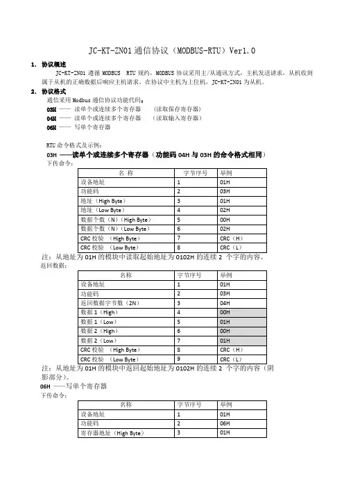
JC-KT-ZN01通信协议(MODBUS-RTU)Ver1.01.协议概述JC-KT-ZN01遵循MODBUS RTU规约,MODBUS协议采用主/从通讯方式,主机发送请求,从机收到属于从机的正确数据后响应主机请求。
在协议中主机为上位机,JC-KT-ZN01为从机。
2.协议格式通信采用Modbus通信协议功能代码:03H——读单个或连续多个寄存器 (读取保存寄存器)04H——读单个或连续多个寄存器(读取输入寄存器)06H——写单个寄存器RTU命令格式及示例:03H ——读单个或连续多个寄存器(功能码04H与03H的命令格式相同)下传命令:返回数据:影部分)。
06H——写单个寄存器下传命令:(阴影部分)。
返回数据:空调命令寄存器数据解析表:高字节解析:00:发码01:学习通信协议举例:(默认地址1,波特率9600)1、读取从地址0002开始的5个寄存器数据发码:01 03 00 02 00 05 24 09返回:01 03 0A 00 01 25 80 01 AB 00 00 00 1E CE 0F或者发码:01 04 00 02 00 05 91 C9返回:01 04 0A 00 01 25 80 01 AA 00 00 00 1E 06 0F注意:功能吗03H和04H在本产品中功能相同上面指令共返回10个字节数据,分别是:地址、波特率、温度、保留寄存器、版本号。
2、学习空调指令(制冷模式,开机,23度)发码:01 06 00 00 01 38 89 88返回:01 06 00 00 01 38 89 883、发送空调指令(制冷模式,开机,23度)发码:01 06 00 00 00 38 88 18返回:01 06 00 00 00 38 88 184、学习空调关机指令(空调关机指令不需要携带模式和温度信息,模式和温度可发送任意数值)发码:01 06 00 00 01 00 88 5A返回:01 06 00 00 01 00 88 5A5、发送空调关机指令(空调关机指令不需要携带模式和温度信息,模式和温度可发送任意数值)发码:01 06 00 00 00 00 89 CA返回:01 06 00 00 00 00 89 CA6、开机指令无需单独学习,除关机指令外的任一空调命令都可开机。
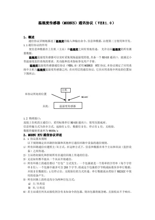
温湿度传感器(MODBUS)通讯协议(V E R1.0)1、概述通信协议详细地描述了温湿度的输入和输出命令、信息和数据,以便第三方使用和开发。
1.1通信协议的作用使信息和数据在上位机(主站)和温湿度之间有效地传递,允许访问温湿度的所有测量数据。
温湿度温湿度传感器可以实时采集现场温湿度的值,具备一个RS485通讯口,能满足小型温湿度监控系统的要求。
其功能和技术指标参见用户手册。
温湿度温湿度传感器通信协议(VER1.0)采用MODBUS RTU协议,本协议规定了应用系统中主机与温湿度温湿度传感器之间,在应用层的通信协议,它在应用系统中所处的位置如下图所示:本协议所处的位置从机:1.2 物理接口:连接上位机的主通信口,采用标准串行RS485通讯口,使用压接底座。
信息传输方式为异步方式,起始位1位,数据位8位,停止位1位,无校验。
数据传输缺省速率为9600b/s2、MODBU RTU通信协议详述2.1 协议基本规则以下规则确定在回路控制器和其他串行通信回路中设备的通信规则。
1)所有回路通信应遵照主/从方式。
在这种方式下,信息和数据在单个主站和从站(监控设备)之间传递。
2)主站将初始化和控制所有在通信回路上传递的信息。
3)无论如何都不能从一个从站开始通信。
4)所有环路上的通信都以“打包”方式发生。
一个包裹就是一个简单的字符串(每个字符串8位),一个包裹中最多可含255个字节。
组成这个包裹的字节构成标准异步串行数据,并按8位数据位,1位停止位,无校验位的方式传递。
串行数据流由类似于RS232C中使用的设备产生。
5)所有回路上的传送均分为两种打包方式:A) 主/从传送B) 从/主传送6)若主站或任何从站接收到含有未知命令的包裹,则该包裹将被忽略,且接收站不予响应。
2.2数据帧结构描述每个数据帧组成如下:RTU模式地址功能代码数据数量数据1...数据nCRC 16位校验3、传输格式(1)命令报文格式返回:(2)、异常应答返回非法功能:非法数据地址:非法数据值:帧格式(10位)4、温湿度温湿度传感器内部报文信息注意:每一个数据用两个字节整数表示,高位在前,低位在后如:带符号整数范围 -32768---32767上传数据需除十,如湿度上传16进制 &H0311,对应十进制00785,表示78.5%上传数据需除十,如温度上传16进制 &H00FFH,对应十进制00255,表示25.5℃上传数据需除十,如温度上传16进制 &H8064,高位为1,表示负数,对应的数高位取反,表示-10.0℃5、网络采样定时温湿度温湿度传感器中,上位机读取数据每次间隔时间不小于500ms,推荐值1s。
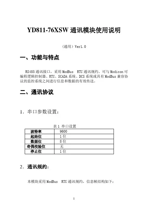
YD811-76XSW通讯模块使用说明(通用)Ver1.0一、功能与特点RS485通讯接口,采用ModBus RTU通讯规约。
可与Modicon可编程逻辑控制器、RTU、SCADA系统、DCS系统或具有ModBus兼容协议的监控系统之间进行信息和数据的有效传送。
二、通讯协议1.串口参数设置:表1 串口设置波特率 9600起始位 1位数据位 8位奇偶校验位无停止位 1位2.通讯规约:本模块采用ModBus RTU通讯规约,信息帧结构如下:表2 信息帧结构地址码功能码数据区校验码8位 8位 N × 8位16位(1)地址码:地址码是信息帧的第一字节(8位),从0到255。
这个字节表明由用户设置地址的从机将接收由主机发送来的信息。
每个从机都必须有唯一的地址码,并且只有符合地址码的从机才能响应回送。
当从机回送信息时,相当的地址码表明该信息来自于何处。
(2)功能码:主机发送的功能码告诉从机执行什么任务。
表3列出的功能码都有具体的含义及操作。
表3 功能码代码含义操作03H 读取数据读取当前寄存器内一个或多个二进制值(3)数据区:数据区包含需要从机执行什么动作或由从机采集的返送信息。
这些信息可以是数值、参考地址等等。
例如,功能码告诉从机读取寄存器的值,则数据区必需包含要读取寄存器的起始地址及读取长度。
对于不同的从机,地址和数据信息都不相同。
(4)错误校验码:主机或从机可用校验码进行判别接收信息是否出错。
有时,由于电子噪声或其它一些干扰,信息在传输过程中会发生细微的变化,错误校验码保证了主机或从机对在传送过程中出错的信息不起作用。
这样增加了系统的安全和效率。
错误校验采用CRC-16校验方法,CRC码低字节在前。
当通讯命令发送至设备时,符合相应地址码的设备接到通讯命令,并除去地址码,读取信息,进行校验。
如果出错则不发送任何信息;如果没有出错,则执行相应的任务,并把执行结果返送给发送方。
返送的信息中包括地址码、执行动作的功能码、执行动作后结果的数据以及错误校验码。

传感器ModBus 通讯协议
V1.00
MS-1406
时间:2014-05
寄存器地址信息表
表格 1 寄存器说明
注意标红的变量都不要
TXKZ 通讯控制字位定义
表格 2 通讯控制字位定义
注:停止位为1位
通讯格式
表格 3 数据格式
表格 4 功能码
读寄存器格式:
表格 5 读寄存器
表格 6 单寄存器返回数据
读取多个寄存器返回数据
表格7 多寄存器返回数据
设置单个寄存器格式:
表格8 设置单个寄存器
表格9 设置单个寄存器返回数据
设置多个寄存器格式:
表格 2 设置多个寄存器
表格 3 设置多个寄存器返回数据
异常回答
举例:
读取从地址01的寄存器地址13开始读取10个寄存器。
由于超出的有效的寄存器地址范围,将返回异常信息。
如下表所示:
表格 4 异常示例
异常响应的中的功能码为功能码|0x80。
如0x04的异常响应功能码是0x84,0x10的异常功能响应码是0x90。
表 5 异常代码。

Modbus通讯协议图片:图片:图片:Modbus协议最初由Modicon公司开发出来,在1979年末该公司成为施耐德自动化(Schneider Automation)部门的一部分,现在Modbus已经是工业领域全球最流行的协议。
此协议支持传统的RS-232、RS-422、RS-485和以太网设备。
许多工业设备,包括PLC,DCS,智能仪表等都在使用Modbus协议作为他们之间的通讯标准。
有了它,不同厂商生产的控制设备可以连成工业网络,进行集中监控。
当在网络上通信时,Modbus协议决定了每个控制器须要知道它们的设备地址,识别按地址发来的消息,决定要产生何种行动。
如果需要回应,控制器将生成应答并使用Modbus协议发送给询问方。
Modbus协议包括ASCII、RTU、TCP等,并没有规定物理层。
此协议定义了控制器能够认识和使用的消息结构,而不管它们是经过何种网络进行通信的。
标准的Modicon控制器使用RS232C实现串行的Modbus。
Modbus的ASCII、RTU 协议规定了消息、数据的结构、命令和就答的方式,数据通讯采用Maser/Slave 方式,Master端发出数据请求消息,Slave端接收到正确消息后就可以发送数据到Master端以响应请求;Master端也可以直接发消息修改Slave端的数据,实现双向读写。
Modbus协议需要对数据进行校验,串行协议中除有奇偶校验外,ASCII模式采用LRC校验,RTU模式采用16位CRC校验,但TCP模式没有额外规定校验,因为TCP协议是一个面向连接的可靠协议。
另外,Modbus采用主从方式定时收发数据,在实际使用中如果某Slave站点断开后(如故障或关机),Master端可以诊断出来,而当故障修复后,网络又可自动接通。
因此,Modbus协议的可靠性较好。
下面我来简单的给大家介绍一下,对于Modbus的ASCII、RTU和TCP协议来说,其中TCP和RTU协议非常类似,我们只要把RTU协议的两个字节的校验码去掉,然后在RTU协议的开始加上5个0和一个6并通过TCP/IP网络协议发送出去即可。

SPM93MODBUS串行通信协议V1.0ZHUHAI PILOT TECHNOLOGY CO.,LTD 珠海派诺科技股份有限公司目录第一章简介 (1)1.1 串行通讯协议的目的 (1)1.2 MODBUS通讯协议的版本 (1)第二章SPM93-MODBUS 串行通信协议详细说明 (2)2.1 SPM93-MODBUS协议基本规则 (2)2.2 传送模式 (2)2.3 MODBUS包裹结构描述 (2)2.4 异常响应 (3)2.5 广播命令 (3)第三章通讯包裹 (4)3.1 读寄存器(功能码03H) (4)3.2 写寄存器(功能码10H) (4)第四章计算CRC-16 (5)第五章SPM93寄存器说明 (7)1、实时测量数据寄存器 (7)2、电度寄存器 (9)3、历史电度数据寄存器 (10)4、设备参数数据寄存器 (18)5、设备信息数据寄存器 (22)第一章简介通信协议详细地描述了SPM93在MODBUS通讯模式下的输入和输出命令、信息和资料,以便第三方使用和开发。
1.1 串行通讯协议的目的通信协议的作用使信息和资料在上位机(主站)和SPM93之间有效地传递,它包括:1)允许主站访问和设定所接SPM93的全部设置参数;2)允许访问SPM93的所有测量资料和事件纪录。
1.2 MODBUS通讯协议的版本该通讯协议适用于本公司已经出厂的所有各种版本的SPM93仪表,对于日后的系列若有改动会加以特别说明。
第二章串行通信协议详细说明2.1 SPM93-MODBUS协议基本规则以下规则确定在RS485(或者RS232C)回路控制器和其它RS485串行通信回路中设备的通信规则:1)所有RS485回路通信应遵照主/从方式。
在这种方式下,信息和资料在单个主站和最多32个从站(监控设备)之间传递;2)主站将初始化和控制所有在RS485通信回路上传递的信息;3)无论如何都不能从一个从站开始通信;4)所有RS485环路上的通信都以“打包”方式发生。


modbus通讯协议【协议名称】:Modbus通讯协议【协议版本】:1.0【协议简介】:Modbus通讯协议是一种用于工业自动化领域的通信协议,用于在不同设备之间进行数据交换和通信。
该协议采用了简单而高效的通信方式,被广泛应用于监控和控制系统中。
本协议旨在规范Modbus通讯的数据格式、传输方式和通信规则,以确保不同设备之间的互操作性和数据的可靠传输。
【协议内容】:1. 物理层:1.1 通信介质:Modbus通讯协议支持多种通信介质,包括串行通信和以太网通信。
串行通信支持RS232、RS485等标准,以太网通信支持TCP/IP协议。
1.2 通信速率:Modbus通讯协议支持多种通信速率,根据实际需求可设置为1200、2400、4800、9600、19200、38400、57600、115200等不同的波特率。
1.3 通信距离:串行通信的最大通信距离根据通信介质的不同而有所差异,一般为几十米至几百米。
以太网通信的最大通信距离受网络设备和布线条件的限制。
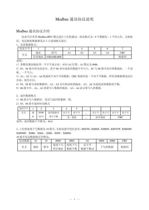
2. 数据帧格式:2.1 传输模式:Modbus通讯协议支持两种传输模式,分别为RTU(Remote Terminal Unit)和ASCII(American Standard Code for Information Interchange)模式。
2.2 数据帧结构:Modbus通讯协议使用了简单的主从结构,数据帧由起始符、从站地址、功能码、数据域、校验码和结束符组成。
2.3 功能码:Modbus通讯协议定义了一系列功能码,用于标识不同的操作类型,如读取寄存器、写入寄存器等。
2.4 数据域:数据域用于存储传输的数据,根据功能码的不同,数据域可以是读取或写入的寄存器值、线圈状态等。
3. 数据读写:3.1 读取数据:主站通过发送读取指令(功能码为03H)给从站,从站根据指令读取相应的数据,并通过响应帧将数据返回给主站。
3.2 写入数据:主站通过发送写入指令(功能码为06H或10H)给从站,从站根据指令将数据写入到指定的寄存器或线圈中,并通过响应帧返回写入结果给主站。

Modbus协议说明中文版Modbus是一种开放的通信协议,用来在工业领域中的设备之间传输数据。
它最早由Modicon公司在1979年开发,用于连接和控制PLC(可编程逻辑控制器)。
现在,Modbus协议已经成为了工业自动化领域最为广泛使用的通信协议之一Modbus协议使用简单、灵活且可靠,适用于各种通信媒介,如串行线缆、以太网和RFID。
它可以通过RS-232、RS-422、RS-485等串行通信方式或TCP/IP协议进行数据传输。
Modbus协议的主要特点包括:1. 简单易用:Modbus协议的指令集简单明了,包括了读和写寄存器的功能。
使用者可以通过设置寄存器的地址和类型来直接读取或写入设备的数据,易于操作。
2. 支持多种数据格式:Modbus协议支持多种数据格式,如二进制、十进制、十六进制和BCD码,便于不同设备之间的数据交换。
3. 支持多个从设备:Modbus协议可以同时连接多个从设备到一个主设备上,方便用户对多个设备进行统一管理和控制。
4. 灵活可扩展:Modbus协议可以根据实际需要进行灵活扩展和定制,包括数据长度、通信速率、通信模式等。
1.主设备发送请求指令:主设备通过通信媒介向从设备发送读写请求指令,包括从设备地址、功能码、寄存器地址和数据等。
2.从设备接收请求指令:从设备接收到请求指令后,根据指令中的寄存器地址和功能码执行相应的操作。
3.从设备发送响应消息:从设备执行完操作后,将结果数据封装成响应消息,包括从设备地址、功能码和数据等,发送给主设备。
4.主设备接收响应消息:主设备接收到响应消息后,解析其中的数据,完成对设备的控制或数据读取操作。
Modbus协议在工业自动化控制中有着广泛的应用,包括了监控和控制系统、远程终端单元(RTU)、人机界面(HMI)等。
它可以实现对灯光、电机、传感器等设备的远程监控和控制,提高工业生产的效率和安全性。
总而言之,Modbus协议作为一种开放的通信协议,通过简单易用、灵活扩展等特点,成为了工业自动化领域中最为广泛使用的通信标准之一、通过使用Modbus协议,工业设备可以方便地实现数据交换和远程控制,提高了工业自动化系统的集成性和可靠性。
Modbus Protocol Reference GuideContents1.Introduction (4)2.Modbus Protocol (4)2.1General Description (4)2.2Modbus Message Framing (5)ASCII Framing (5)RTU Framing (5)Address Field (5)Function Field (5)Data Field (5)Error Checking Field (6)LRC Checking (6)CRC Checking (6)2.3 Modbus Function Formats (7)Data Address (7)Coil (7)Input Status (7)Input Register (7)Holding Register (7)2.4Field Contents in Modbus Messages (8)3.Modbus Function Codes (9)3.1Read Coil Status (01) (9)3.2Read Input Status (02) (10)3.3Read Holding Register (03) (11)3.4Read Input Register (04) (12)3.5Force Single Coil (05) (13)3.6Preset Single Register (06) (14)3.7Diagnostics (08) (15)3.8Fetch Communication Event Counter (11, 0XB) (16)3.9Fetch Communication Event Log (12, 0XC) (17)3.10Force Multiple Coils (15, 0X0F) (18)3.11Preset Multiple Registers (16, 0X10) (19)3.12Report Slave ID (17, 0X11) (20)All trademarks are the sole property of their respective owners.4.Diagnostic Subfunctions (08) (21)4.1Return Query Data (00) (21)4.2Restart Communications Option (01) (21)4.3Return Diagnostics Register (02) (21)4.4Force Listen Only Mode (04) (21)4.5Clear Counters and Diagnostic Register (10, 0X4A) (21)4.6Return Bus Message Count (11, 0X0B) (21)4.7Return Bus Communication Error Count (12, 0X0C) (21)4.8Return Bus Exception Error Count (13, 0X0D) (22)4.9Return Slave Message Count (14, 0X0E) (22)4.10Return Slave No Response Count (15, 0X0F) (22)4.11Return Slave Busy Count (17, 0X11) (22)4.12Return Bus Character Overrun Count (18, 0X12) (22)5.Exception Responses (23)Appendix A. R1M Series Remote I/O Modbus Communications (25)A-1Function Codes (25)A-2Data Addresses (25)A-3Coils (DO) Description (25)DO (1 – 32) (25)Cold Junction Compensation SW (33 – 48) (25)A-4Input Status (DI) Description (26)DI (10001 – 10032) (26)ADC Overrange (10033 – 10048) (26)A-5Input Registers Description (26)Analog Input in % (30001 – 30016) (26)Analog Input in Engineering Unit (30017 – 30048) (26)Cold Junction Temperature (30049 – 30050) (26)Channel Status (30081 – 30096) (27)System Status (30513) (27)Model No. (30514 – 30521) (27)Serial No. (30522 – 30529) (27)Hardware Version No. (30530 – 30537) (27)Firmware Version No. (30538 – 30545) (27)A-6Holding Registers Description (28)Analog Output in % (40001 – 40016) (28)Analog Output in Engineering Unit (40017 – 40048) (28)I/O Type No. (40145 – 40160) (28)Burnout T ype (40161 – 40176) (28)Appendix B. R2M Remote I/O Modbus Communications (29)B-1Function Codes (29)B-2Data Addresses (29)B-3Coils (DO) Description (29)DO (1 – 32) (29)Cold Junction Compensation SW (33 – 40) (29)B-4Input Status (DI) Description (30)DI (10001 – 10032) (30)ADC Overrange (10033 – 10040) (30)B-5Input Registers Description (30)Analog Input in Engineering Unit (30017 – 30032) (30)Cold Junction Temperature (30049 – 30050) (30)Channel Status (30081 – 30088) (30)System Status (30513) (31)Model No. (30514 – 30521) (31)Serial No. (30522 – 30529) (31)Hardware Version No. (30530 – 30537) (31)Firmware Version No. (30538 – 30545) (31)B-6Holding Registers Description (32)Input Filter Time Constant (40049 – 40050) (32)Input Type No. (40145 – 40152) (32)Burnout Type (40514) (32)Appendix C. Modbus TCP/IP Protocol (33)C-1Introduction (33)C-2Protocol Layout (33)C-3Example (34)C-4Point of Caution (34)1.IntroductionThe Modbus protocol is provided by Modicon Inc. (AEG Schneider Automation International S.A.S.), originally developed for Modicon programmable controllers. Detailed information is described in Modicon Modbus Protocol Reference Guide (PI-MBUS-300 Rev. J).This protocol defines a message structure, regardless of the physical layer such like the type of networks over which they communicate.2.Modbus Protocol2.1General DescriptionThe Modbus devices communicate using a master-slave technique, in which only one device (the master) can initiate trans-actions (called ‘queries’). The other devices (the slaves) respond by supplying the requested data to the master, or by taking the action requested in the query.The master can address individual slaves, or can initiate a broadcast messages to all slaves. Slaves return a message (called a ‘response’) to queries that are addressed to them individually. Responses are not returned to broadcast queries from the master.The Modbus protocol establishes the format for the master’s query by placing into it the device (or broadcast) address, a function code defining the requested action, any data to be sent, and an error-checking field. The slave’s response message is also constructed using Modbus protocol. It contains fields confirming the action taken, any data to be returned, and an error-checking field.The figure below illustrates a query-response cycle.Devices can be setup to communicate on standard Modbus networks either of two transmission modes: ASCII (American Standard Code for Information Interchange) or RTU (Remote Terminal Unit). The mode must be the same for all devices on a Modbus network.In ASCII mode, each 8-bit byte in a message is sent as two ASCII characters. In RTU mode, each 8-bit byte in a message contains two 4-bit hexadecimal characters. The RTU mode, with its greater character density, allows better data throughput than ASCII for the same baud rate.The checking algorithm used in the Error Check Field depends upon which transmission method is employed; LRC (Longitu-dinal Redundancy Check) in ASCII mode; CRC (Cyclical Redundancy Check) in RTU mode.2.2Modbus Message FramingASCII FramingIn ASCII mode, messages start with a ‘colon’ ( : ) character (ASCII 0X3A), and end with a ‘carriage return – line feed’ (CRLF) pair (ASCII 0X0D and 0X0A). The allowable characters transmitted for all other fields are hexadecimal 0 – 9, A – F.When the messages are to be sent over Ethernet, this message frame is handled as a data frame in TCP/IP protocol. Dividing a message frame is not allowed.START ADDRESS FUNCTION DATA LRC CHECK END1 CHAR:2 CHARS 2 CHARS n CHARS 2 CHARS 2 CHARSCRLFFigure 1. ASCII Message FrameRTU FramingIn RTU mode, messages start with a silent interval of at least 3.5 character times, and end with a similar interval of at least 3.5 character times. This is most easily implemented as a multiple of character times at the baud rate that is being used on the network (shown as T1 – T2 – T3 – T4 in the figure below).All other fields are composed of 8-bit data.START ADDRESS FUNCTION DATA CRC CHECK END8 BITST1–T2–T3–T48 BITS n x 8 BITS16 BITS T1–T2–T3–T4 Figure 2. RTU Message FrameAddress FieldValid slave device addresses are in the range of 0 – 247 decimal. The individual slave devices are assigned addresses in the range of 1 – 247. A master addresses a slave by placing the slave address in the address field of the message. When the slave sends its response, it places its own address in this address field of the response to let the master know which slave is responding. Address 0 is used for the broadcast query.Function FieldValid function field codes are in the range of 1 – 255 decimal.When a message is sent from a master to a slave device the function code field tells the slave what kind of action to perform. When the slave responds to the master, it uses the function code field to indicate either a normal (error-free) response or that some kind of error occurred (called an exception response). For a normal response, the slave simply echoes the original function code. For an exception response, the slave returns a code that is equivalent to the original function code with its most-significant bit set to a logic 1. This tells the master what kind of error occurred, or the reason for the exception. Whether a particular function code is applicable or not depends upon the slave device. Check specifications for each slave device.Data FieldThe data field of messages sent from a master to slave devices contains information which the slave must use to take the action defined by the function code. The data field may be of various length, or can be nonexistent (of zero length). Refer to specifications for each slave device for the constructions and meaning of the data field.Error Checking FieldASCIIWhen ASCII mode is used for character framing the error checking field contains two ASCII characters. The error check characters are the result of a Longitudinal Redundancy Check (LRC) calculation that is performed on the message content, exclusive of the beginning ‘colon’ and terminating CRLF characters.RTUWhen RTU mode is used for character framing, the error checking field contains a 16-bit value implemented as two 8-bit bytes. The error check value is the result of a Cyclical Redundancy Check calculation performed on the message contents.LRC CheckingIn ASCII mode, messages include an error-checking field that is based on a Longitudinal Redundancy Check (LRC) method. The LRC field checks the contents of the message, exclusive of the beginning ‘colon’ and ending CRLF pair. It is applied regardless of any parity check method used for the individual characters of the message.The LRC field is one byte, containing an 8-bit binary value. The LRC value is calculated by the transmitting device, which appends the LRC to the message. The receiving device calculates an LRC during receipt of the message, and compares the calculated value to the actual value it received in the LRC field. If the two values are not equal, an error results.The LRC is calculated by adding together successive 8-bit bytes of the message, discarding any carries, and then two’s complementing the result. It is performed on the ASCII message field contents excluding the ‘colon’ character that begins the message, and excluding the CRLF pair at the end of the message.CRC CheckingIn RTU mode, messages include an error-checking field that is based on a Cyclical Redundancy Check (CRC) method. The CRC field checks the contents of the entire message. It is applied regardless of any parity check method used for the individual characters of the message.The CRC field is two bytes, containing a 16-bit binary value. The CRC value is calculated by the transmitting device, which appends the CRC to the message. The receiving device recalculates a CRC during receipt of the message, and compares the calculated value to the actual value it received in the CRC field. If the two values are not equal, an error results.The CRC is started by first preloading a 16-bit register to all 1’s. Then a process begins of applying successive 8-bit bytes of the message to the current contents of the register. Only the eight bits of data in each character are used to generating the CRC. Start and stop bits, and the parity bit if one is used, do not apply to the CRC.During generation of the CRC, each 8-bit character is exclusive ORed with the register contents. Then the result is shifted in the direction of the least significant bit (LSB), with a zero filled into the most significant bit (MSB) position. The LSB is extracted and examined. If the LSB was a 1, the register is then exclusive ORed with a preset, fixed value. If the LSB was a 0, no exclusive OR takes place.This process is repeated until eight shifts have been performed. After the last (eighth) shift, the next 8-bit byte is exclusive ORed with the register’s current value, and the process repeats for eight more shifts as described above. The final contents of the register, after all the bytes of the message have been applied, is the CRC value.When the CRC is appended to the message, the low-order byte of the field is appended first, followed by the high-order byte.2.3 Modbus Function FormatsData AddressData addresses are used in Modbus query messages when reading or modifying data. Four types of data are used: Coil, Input Status, Input Register and Holding Register.CoilCoils are used to force the ON/OFF state of discrete outputs (DO) to the field, or to modify the mode or status of slave devices. Coil data is either ON or OFF, which can be both read and modified. Valid addresses are in the range of 1 – 9999.Input StatusInput Status is used for the ON/OFF state of discrete inputs (DI) from the field, or the status of slave devices. The input status is either ON or OFF, which can be read only. Valid addresses are in the range of 10001 – 19999.Input RegisterInput registers are used for the value of analog inputs (AI) from the field, or the information of slave devices. The input register is of 16-bit long, which can be read only. Valid addresses are in the range of 30001 – 39999. Floating or double-floating data can be handled when consecutive addresses are assigned.Holding RegisterHolding registers are used for the value of analog outputs (AO) to the field, or to set information of slave devices. The holding register is of 16-bit long, which can be both read and modified. Valid addresses are in the range of 40001 – 49999. Floating or double-floating data can be handled when consecutive addresses are assigned.2.4Field Contents in Modbus MessagesAll data addresses in Modbus messages are referenced to 0. The first occurrence of a data item is addressed as item number zero. For example, the input register 30156 decimal is addressed as register 155 decimal in the message field. The function code field specifies data type.Figure 3 shows an example of a Modbus query message. The master query is a Read Holding Registers request (function code 03) to slave device address 06. The message requests data from three holding registers, 40108 through 40110. Note that the messages specifies the starting register address as 107 (0X6B hex).Field Name Example ASCII RTU(Hex)Characters8-Bit Field (Hex)Header: (colon)NoneSlave Address0X060 60X06Function0X030 30X03Starting Address Hi0X000 00X00Starting Address Lo0X6B 6 B0X6BNo. of Registers Hi0X000 00X00No. of Registers Lo0X030 30X03Error Check LRC (2 chars.)CRC (16 bits)Trailer CR LF NoneTotal Bytes:178Figure 3. Example of Master QueryFigure 4 is an example of a normal response from the slave to the master query shown in Figure 3. The slave response echoes the slave address and function code. The ‘Byte Count’ field specifies how many 8-bit data items are being returned. Note that the value does not represent the actual character count transmitted in either ASCII or RTU mode. In this example, the message contains three sets of 16-bit data, therefore the ‘Byte Count’ is ‘6’ regardless of the character framing method.Field Name Example ASCII RTU(Hex)Characters8-Bit Field (Hex)Header: (colon)NoneSlave Address0X060 60X06Function0X030 30X03Byte Count0X060 60X06Data 1 Hi0X030 30X03Data 1 Lo0XE8 E 80XE8Data 2 Hi0X010 10X01Data 2 Lo0XF4 F 40XF4Data 3 Hi0X000 00X00Data 3 Lo0X0A0 A0X0AError Check LRC (2 chars.)CRC (16 bits)Trailer CR LF NoneTotal Bytes:2311Figure 4. Example of Slave Response3.Modbus Function Codes3.1Read Coil Status (01)DescriptionRead the ON/OFF status of discrete outputs (DO) in the slave. Broadcast is not supported. Refer to specifications of the slave device for data addresses and their contents.QueryThe query message specifies the starting coil and quantity of coils to be read. Here is an example of a request to read coils 20 – 56, 37 coils in total, from slave device 3: (Note that the Starting Address is of 19 or 0X13, less than the coil 20 by 1.)Field Name Example ASCII RTU(Hex)Characters8-Bit Field (Hex)Header: (colon)NoneSlave Address0X030 30X03Function0X010 10X01Starting Address Hi0X000 00X00Starting Address Lo0X13 1 30X13No. of Registers Hi0X000 00X00No. of Registers Lo0X25 2 50X25Error Check LRC (2 chars.)CRC (16 bits)Trailer CR LF NoneTotal Bytes:178Figure 5. Read Coil Status – QueryResponseThe coil status in the response message is packed as one coil per bit of the data field. Status is indicated as: 1 = ON, 0 = OFF. The LSB of the first data byte contains the coil addressed in the query.For example, when the status of coils 20 – 27 is sho w n ON – ON – OFF – OFF – ON – OFF – ON – OFF, represented as the byte value binary 0101 0011 (0X53). One byte contains the status for eight coils. If the coil quantity is not a multiple of eight, the remaining bits in the final data byte will be padded with zeros.Figure 6 shows an example of a response to the query shown in Figure 5.Field Name Example ASCII RTU(Hex)Characters8-Bit Field (Hex)Header: (colon)NoneSlave Address0X030 30X03Function0X010 10X01Byte Count0X050 50X05Data 10X53 5 30X53Data 20X6B 6 B0X6BData 30X010 10X01Data 40XF4 F 40XF4Data 50X1B 1 B0X1BError Check LRC (2 chars.)CRC (16 bits)Trailer CR LF NoneTotal Bytes:2110Figure 6. Read Coil Status – Response3.2Read Input Status (02)DescriptionRead the ON/OFF status of discrete inputs (DI) in the slave. Broadcast is not supported. Refer to specifications of the slave device for data addresses and their contents.QueryThe query message specifies the starting input and quantity of inputs to be read. Here is an example of a request to read inputs 10101 – 10120, 20 inputs in total, from slave device 3: (Note that the Starting Address is of 100 or 0X64, less than the input 10101 by 10001.)Field Name Example ASCII RTU(Hex)Characters8-Bit Field (Hex)Header: (colon)NoneSlave Address0X030 30X03Function0X020 20X02Starting Address Hi0X000 00X00Starting Address Lo0X64 6 40X64No. of Registers Hi0X000 00X00No. of Registers Lo0X14 1 40X14Error Check LRC (2 chars.)CRC (16 bits)Trailer CR LF NoneTotal Bytes:178Figure 7. Read Input Status – QueryResponseThe construction of the response message is the same as that for Real Coil Status (01) operation.Figure 8 shows an example of a response to the query shown in Figure 7.Field Name Example ASCII RTU(Hex)Characters8-Bit Field (Hex)Header: (colon)NoneSlave Address0X030 30X03Function0X020 20X02Byte Count0X030 30X03Data 10X53 5 30X53Data 20X6B 6 B0X6BData 30X010 10X01Error Check LRC (2 chars.)CRC (16 bits)Trailer CR LF NoneTotal Bytes:178Figure 8. Read Input Status – Response3.3Read Holding Register (03)DescriptionRead the binary contents of holding registers in the slave. Broadcast is not supported. Refer to specifications of the slave device for data addresses and their contents.QueryThe query message specifies the starting register and quantity of registers to be read. Here is an example of a request to read registers 40201 – 40203, 3 registers in total, from slave device 7: (Note that the Starting Address is of 200 or 0XC8, less than the register 40201 by 40001.)Field Name Example ASCII RTU(Hex)Characters8-Bit Field (Hex)Header: (colon)NoneSlave Address0X070 70X07Function0X030 30X03Starting Address Hi0X000 00X00Starting Address Lo0XC8 C 80XC8No. of Registers Hi0X000 00X00No. of Registers Lo0X030 30X03Error Check LRC (2 chars.)CRC (16 bits)Trailer CR LF NoneTotal Bytes:178Figure 9. Read Holding Register – QueryResponseThe register data in the response message are packed as 16 bits per register. Figure 10 shows an example of a response to the query shown in Figure 9.Field Name Example ASCII RTU(Hex)Characters8-Bit Field (Hex)Header: (colon)NoneSlave Address0X070 70X07Function0X030 30X03Byte Count0X060 60X06Data 1 Hi0X030 30X03Data 1 Lo0XE8 E 80XE8Data 2 Hi0X010 10X01Data 2 Lo0XF4 F 40XF4Data 3 Hi0X000 00X00Data 3 Lo0X0A0 A0X0AError Check LRC (2 chars.)CRC (16 bits)Trailer CR LF NoneTotal Bytes:2311Figure 10. Read Holding Register – Response3.4Read Input Register (04)DescriptionRead the binary contents of input registers in the slave. Broadcast is not supported. Refer to specifications of the slave device for data addresses and their contents.QueryThe query message specifies the starting register and quantity of registers to be read. Here is an example of a request to read registers 30301 – 30303, 3 registers in total, from slave device 7: (Note that the Starting Address is of 300 or 0X12C, less than the register 30301 by 30001.)Field Name Example ASCII RTU(Hex)Characters8-Bit Field (Hex)Header: (colon)NoneSlave Address0X070 70X07Function0X040 40X04Starting Address Hi0X010 10X01Starting Address Lo0X2C 2 C0X2CNo. of Registers Hi0X000 00X00No. of Registers Lo0X030 30X03Error Check LRC (2 chars.)CRC (16 bits)Trailer CR LF NoneTotal Bytes:178Figure 11. Read Input Register – QueryResponseThe register data in the response message are packed as 16 bits per register. Figure 12 shows an example of a response to the query shown in Figure 11.Field Name Example ASCII RTU(Hex)Characters8-Bit Field (Hex)Header: (colon)NoneSlave Address0X070 70X07Function0X040 40X04Byte Count0X060 60X06Data 1 Hi0X030 30X03Data 1 Lo0XE8 E 80XE8Data 2 Hi0X010 10X01Data 2 Lo0XF4 F 40XF4Data 3 Hi0X000 00X00Data 3 Lo0X0A0 A0X0AError Check LRC (2 chars.)CRC (16 bits)Trailer CR LF NoneTotal Bytes:2311Figure 12. Read Input Register – Response3.5Force Single Coil (05)DescriptionForces a single coil to either ON or OFF of the discrete output (DO) status in the slave. When broadcast, the function forces the same coil reference in all attached slaves. Refer to specifications of the slave device for data addresses and their contents.QueryThe query message specifies the coil reference (the starting coil and the state) to be forced. The requested ON/OFF state is specified by a constant in the query data field. A value of 00FF, 0X00 requests the coil to be ON. A value of 0X00, 0X00 requests it to be OFF. All other values are illegal and will not affect the coil.Here is an example of a request to force coil 150 ON in slave device 3: (Note that the Starting Address is of 149 or 0X95, less than the force coil 150 by 1.)Field Name Example ASCII RTU(Hex)Characters8-Bit Field (Hex)Header: (colon)NoneSlave Address0X030 30X03Function0X050 50X05Starting Address Hi0X000 00X00Starting Address Lo0X959 50X95No. of Registers Hi0XFF F F0XFFNo. of Registers Lo0X000 00X00Error Check LRC (2 chars.)CRC (16 bits)Trailer CR LF NoneTotal Bytes:178Figure 13. Force Single Coil – QueryResponseThe normal response is an echo of the query. Figure 14 shows an example of a response to the query shown in Figure 13.Field Name Example ASCII RTU(Hex)Characters8-Bit Field (Hex)Header: (colon)NoneSlave Address0X030 30X03Function0X050 50X05Starting Address Hi0X000 00X00Starting Address Lo0X959 50X95No. of Registers Hi0XFF F F0XFFNo. of Registers Lo0X000 00X00Error Check LRC (2 chars.)CRC (16 bits)Trailer CR LF NoneTotal Bytes:178Figure 14. Force Single Coil – Response3.6Preset Single Register (06)DescriptionPresets a value into a single holding register. When broadcast, the function presets the same register reference in all attached slaves. Refer to specifications of the slave device for data addresses and their contents.QueryThe query message specifies the register reference to be preset. The requested preset value is specified as 16-bit data in the query data field.Here is an example of a request to preset register 1000 to 150 in slave device 3: (Note that the Starting Address is of 149 or 0X95, less than the force coil 150 by 1.)Field Name Example ASCII RTU(Hex)Characters8-Bit Field (Hex)Header: (colon)NoneSlave Address0X030 30X03Function0X060 60X06Starting Address Hi0X000 00X00Starting Address Lo0X959 50X95No. of Registers Hi0X030 30X03No. of Registers Lo0XE8 E 80XE8Error Check LRC (2 chars.)CRC (16 bits)Trailer CR LF NoneTotal Bytes:178Figure 15. Preset Single Register – QueryResponseThe normal response is an echo of the query. Figure 16 shows an example of a response to the query shown in Figure 15.Field Name Example ASCII RTU(Hex)Characters8-Bit Field (Hex)Header: (colon)NoneSlave Address0X030 30X03Function0X060 60X06Starting Address Hi0X000 00X00Starting Address Lo0X959 50X95No. of Registers Hi0X030 30X03No. of Registers Lo0XE8 E 80XE8Error Check LRC (2 chars.)CRC (16 bits)Trailer CR LF NoneTotal Bytes:178Figure 16. Preset Single Register – Response3.7Diagnostics (08)DescriptionProvides a series of tests for checking the communication system between the master and slave, or for checking various internal error conditions within the slave. Broadcast is not supported.The function uses a two-byte subfunction code field in the query to define the type of test to be performed. The slave echoes both the function code and subfunction code in a normal response.Most of the diagnostic queries use a two-byte data field to send diagnostic data or control information to the slave.For detailed information on Diagnostics Subfunctions, refer to Section 4. Diagnostics Subfunctions (08).QueryHere is an example of a request to slave device 5 to Return Query Data. This uses a subfunction code of zero (0X0000).Field Name Example ASCII RTU(Hex)Characters8-Bit Field (Hex)Header: (colon)NoneSlave Address0X050 50X05Function0X080 80X08Subfunction Hi0X000 00X00Subfunction Lo0X000 00X00Data Hi0X030 30X03Data Lo0XE8 E 80XE8Error Check LRC (2 chars.)CRC (16 bits)Trailer CR LF NoneTotal Bytes:178Figure 17. Diagnostics – QueryResponseThe normal response to the Return Query Data request is a loopback of the same data. Figure 18 shows an example of a response to the query shown in Figure 17.Field Name Example ASCII RTU(Hex)Characters8-Bit Field (Hex)Header: (colon)NoneSlave Address0X050 50X05Function0X080 80X08Subfunction Hi0X000 00X00Subfunction Lo0X000 00X00Data Hi0X030 30X03Data Lo0XE8 E 80XE8Error Check LRC (2 chars.)CRC (16 bits)Trailer CR LF NoneTotal Bytes:178Figure 18. Diagnostics – Response3.8Fetch Communication Event Counter (11, 0XB)DescriptionReturns a status word and an event count from the slave’s communication event counter. By fetching the current count before and after a series of messages, a master can determine whether the messages were handled normally by the slave. Broadcast is not supported.The controller’s event counter is incremented once for each successful message completion. It is not incremented for exception responses, poll commands, or fetch event counter commands.The event counter can be reset by means of the Diagnostics function (08), with a subfunction of Restart Communications Option (code 0X0001) or Clear Counters and Diagnostic Register (code 0X000A).QueryHere is an example of a request to fetch the communications event counter in slave device 5:Field Name Example ASCII RTU(Hex)Characters8-Bit Field (Hex)Header: (colon)NoneSlave Address0X050 50X05Function0X0B0 B0X0BError Check LRC (2 chars.)CRC (16 bits)Trailer CR LF NoneTotal Bytes:94Figure 19. Fetch Communications Event Counter – QueryResponseThe normal response contains a two-byte status word, and a two-byte event count. Figure 20 shows an example of a response to the query shown in Figure 19.Field Name Example ASCII RTU(Hex)Characters8-Bit Field (Hex)Header: (colon)NoneSlave Address0X050 50X05Function0X0B0 B0X0BStatus Hi0X000 00X00Status Lo0X000 00X00Event Count Hi0X030 30X03Event Count Lo0XE8 E 80XE8Error Check LRC (2 chars.)CRC (16 bits)Trailer CR LF NoneTotal Bytes:178Figure 20. Fetch Communications Event Counter – Response。
Modbus通讯协议简化V1.0 2004-5-21 1 Modbus协议概述Modbus协议是主从站通讯协议,用异步串行口完成通讯,物理层采用RS485或RS232。
传输速率可以达到115kbps,理论上可接(寻址)一台主站和至多247台从站。
受线路和设备的限制,最多可接一台主站和32台从站。
Modbus理,以及所执行的功能等,都不能随便改动。
其他特性属于用户可选的,如传输介质、波特率、字符奇偶校验、停止位的个数等等,传输模式为RTU。
用户所选择的参数对于各个站必须一致,在系统运行时不能改变。
1.1 Modbus协议传输模式Modbus的传输模式:RTU方式。
表1-1 RTU传输模式的特性特性编码系统每个字符的位数起始位数据位奇偶校验位停止位1.2 帧Modbus协议的帧(报文)格式:RTU帧。
下表是RTU传输模式的一般格式命令帧。
从站地址8位2 Modbus协议2.1 通讯方式Modbus有两种通讯方式:应答方式和广播方式。
应答方式是主站向某个从站(地址1~247)发出命令,然后等待从站的应答;从站接到主站命令后,执行命令,并将执行结果返回给主站作为应答,然后等待下一个命令。
广播方式是主站向所有从站发送命令(从站地址为0),不需要等待从站应答;从站接到广播命令后,执行命令,也不向主站应答。
除了会送诊断校验外,只有05、06、15、16这四项功能(见2.3)对广播方式有效。
功能码数据校验和 8位位位十六进制 1位 8位 0或1位 1或2位校验和(循环冗余校验)2.2 Modbus帧Modbus的帧按应答方式分为命令帧(询问帧)和应答帧。
命令帧为一般格式命令帧,应答帧有显长度帧和隐长度帧之分,图2-1、2-3、2-4给出了典型的帧格式。
从站地址功能码数据数据起始寄存器高位数据起始寄存器地位数据寄存器高位数据寄存器地位校验和图2-1 一般格式命令帧从站地址从站地址2.2.1功能码从站地址字段数据图2-4 隐长度应答帧帧中的从站地址字段表示接收主站报文的从站地址。
第二章:Modbus 通信协议说明Modbus 通信协议基本上是遵循Master and Slave 的通信步骤,有一方扮演Master 角色采取主动询问方式,送出Query Message 给Slave 方,然后由Slave 方依据接到的Query Message 内容准备Response Message 回传给Master 。
即使目前硬件通信已经可以达到双方互相主动通信的能力,但是于Modbus 通信协议的规定,必须一方为Master ,另一方为Slave 不能互换角色。
一般使用上,监控系统(HMI)都为Master ,PLC 、电表、仪表等都为Slave ,HMI 系统一直Polling Slave 的各种relay and register 最新数值,然后做显示及各种逻辑计算及控制调整等处理。
1 共享的通信协议1.1 Query and Response Cycle图(2-1):Master / Slave and Query / Response CycleDevice Address :表示该设备的编号,于同一个串行式网络上此为唯一的号码。
于TCP/IP 上可以使用IP Address 区分之,所以该Device Address 保留此字段可以使用或不使用。
Function Code :表示要求Slave 处理各种不同资料或程序的Command ,以不同的Function Number 来区分之。
Eight-Bit Data Bytes :依据Function Code 而有不同的详细资料定义,Slave 设备依据此两字段资料,做各种处理。
Error Check :当通信传送资料时,因考虑信号可能会受外界干扰,所以必须加上Error Check Code ,使得message 接收方可以就接到的资料再计算一次Code ,如果正确则做正常处理,不正确则不做处理。
于串行式通信规定有CRC and LRC 等两种方式。
Modbus通信协议详情教程Modbus通信协议是一种用于工业自动化领域的通信协议,它被广泛应用于各种工业控制系统中。
本教程将介绍Modbus通信协议的详细内容,包括其基本原理、通信方式和通信数据格式等方面的知识。
一、Modbus通信协议简介Modbus通信协议是由Modicon(现在是施耐德电气公司的子公司)在1979年开发的,它是一种基于主从架构的协议。
该协议采用简单、通用的方式实现设备之间的数据交换,使得不同厂家的设备之间能够进行有效的通信。
二、Modbus通信架构Modbus通信协议包括两种模式:RTU(Remote Terminal Unit)和ASCII(American Standard Code for Information Interchange)。
RTU模式是常用的模式,它通过串行通信实现数据传输,数据被编码为二进制格式,具有较高的通信速度和可靠性。
ASCII模式则是通过串行通信传输可打印字符编码的文本数据,通信速度较慢,但具有更好的人机界面。
三、Modbus通信方式Modbus通信协议定义了两种通信方式:请求-响应模式和发布-订阅模式。
在请求-响应模式下,主节点向从节点发送请求,从节点接收到请求后进行处理并返回响应。
在发布-订阅模式下,主节点向从节点发送订阅请求,从节点将数据主动发布给主节点。
四、Modbus通信数据格式Modbus通信协议定义了几种常用的数据格式,包括保持寄存器、输入寄存器、线圈和离散输入等。
其中,保持寄存器用于存储设备参数和状态信息,输入寄存器用于读取传感器数据,线圈用于控制设备的开关状态,离散输入用于读取设备的输入状态。
五、Modbus通信应用领域Modbus通信协议广泛应用于各种工业自动化领域,包括工厂自动化、能源管理、楼宇自动化、环境监测等。
通过使用Modbus通信协议,不同厂家的设备可以实现互联互通,提高生产效率和管理水平。
六、Modbus通信安全性由于Modbus通信协议的设计初衷是简单易用,没有考虑通信安全性,因此在实际应用中存在一定的安全风险。
Modbus通信协议一、Modbus 协议简介Modbus 协议是应用于电子控制器上的一种通用语言。
通过此协议,控制器相互之间、控制器经由网络(例如以太网)和其它设备之间可以通信。
它已经成为一通用工业标准。
有了它,不同厂商生产的控制设备可以连成工业网络,进行集中监控。
此协议定义了一个控制器能认识使用的消息结构,而不管它们是经过何种网络进行通信的。
它描述了一控制器请求访问其它设备的过程,如果回应来自其它设备的请求,以及怎样侦测错误并记录。
它制定了消息域格局和内容的公共格式。
当在一Modbus网络上通信时,此协议决定了每个控制器须要知道它们的设备地址,识别按地址发来的消息,决定要产生何种行动。
如果需要回应,控制器将生成反馈信息并用Modbus协议发出。
在其它网络上,包含了Modbus协议的消息转换为在此网络上使用的帧或包结构。
这种转换也扩展了根据具体的网络解决节地址、路由路径及错误检测的方法。
1、在Modbus网络上转输标准的Modbus口是使用一RS-232C兼容串行接口,它定义了连接口的针脚、电缆、信号位、传输波特率、奇偶校验。
控制器能直接或经由Modem组网。
控制器通信使用主—从技术,即仅一设备(主设备)能初始化传输(查询)。
其它设备(从设备)根据主设备查询提供的数据作出相应反应。
典型的主设备:主机和可编程仪表。
典型的从设备:可编程控制器。
主设备可单独和从设备通信,也能以广播方式和所有从设备通信。
如果单独通信,从设备返回一消息作为回应,如果是以广播方式查询的,则不作任何回应。
Modbus协议建立了主设备查询的格式:设备(或广播)地址、功能代码、所有要发送的数据、一错误检测域。
从设备回应消息也由Modbus协议构成,包括确认要行动的域、任何要返回的数据、和一错误检测域。
如果在消息接收过程中发生一错误,或从设备不能执行其命令,从设备将建立一错误消息并把它作为回应发送出去。
2、在其它类型网络上转输在其它网络上,控制器使用对等技术通信,故任何控制都能初始和其它控制器的通信。
(完整版)MODBUS协议(功能码及报文解析)(可编辑修改word版)MODBUS 协议Modbus 是一种串行通信协议,是Modicon 于 1979 年,为使用可编程逻辑控制器(PLC)而发表的。
事实上,它已经成为工业领域通信协议标准,并且现在是工业电子设备之间相当常用的连接方式。
Mod bus 比其他通信协议使用的更广泛的主要原因有:公开发表并且无版税要求相对容易的工业网络部署对供应商来说,修改移动原生的位或字节没有很多限制Modbus 允许多个设备连接在同一个网络上进行通信,举个例子,一个由测量温度和湿度的装置,并且将结果发送给计算机。
在数据采集与监视控制系统(SCADA)中,Modbus 通常用来连接监控计算机和 rem ote terminal unit (RTU)。
Modbus 协议目前存在用于串口、以太网以及其他支持互联网协议的网络的版本。
大多数 Modbus 设备通信通过串口EIA-485 物理层进行[1]。
对于串行连接,存在两个变种,它们在数值数据表示不同和协议细节上略有不同。
Modbus RTU 是一种紧凑的,采用二进制表示数据的方式,Modbus ASCII 是一种人类可读的,冗长的表示方式。
这两个变种都使用串行通讯(serial communication)方式。
RTU 格式后续的命令/数据带有循环冗余校验的校验和,而ASCII 格式采用纵向冗余校验的校验和。
被配置为 RTU 变种的节点不会和设置为 ASCII 变种的节点通信,反之亦然。
对于通过TCP/IP(例如以太网)的连接,存在多个 Modbus/TCP 变种,这种方式不需要校验和的计算。
对于所有的这三种通信协议在数据模型和功能调用上都是相同的,只有封装方式是不同的。
Modbus 有一个扩展版本 Modbus Plus(Modbus+或者 MB+),不过此协定是Modicon 专有的,和 Modbus 不同。
它需要一个专门的协处理器来处理类似HDLC 的高速令牌旋转。
Modbus通讯协议简化V1.0 2004-5-21 1 Modbus协议概述Modbus协议是主从站通讯协议,用异步串行口完成通讯,物理层采用RS485或RS232。
传输速率可以达到115kbps,理论上可接(寻址)一台主站和至多247台从站。
受线路和设备的限制,最多可接一台主站和32台从站。
Modbus理,以及所执行的功能等,都不能随便改动。
其他特性属于用户可选的,如传输介质、波特率、字符奇偶校验、停止位的个数等等,传输模式为RTU。
用户所选择的参数对于各个站必须一致,在系统运行时不能改变。
1.1 Modbus协议传输模式Modbus的传输模式:RTU方式。
表1-1 RTU传输模式的特性特性编码系统每个字符的位数起始位数据位奇偶校验位停止位1.2 帧Modbus协议的帧(报文)格式:RTU帧。
下表是RTU传输模式的一般格式命令帧。
从站地址8位2 Modbus协议2.1 通讯方式Modbus有两种通讯方式:应答方式和广播方式。
应答方式是主站向某个从站(地址1~247)发出命令,然后等待从站的应答;从站接到主站命令后,执行命令,并将执行结果返回给主站作为应答,然后等待下一个命令。
广播方式是主站向所有从站发送命令(从站地址为0),不需要等待从站应答;从站接到广播命令后,执行命令,也不向主站应答。
除了会送诊断校验外,只有05、06、15、16这四项功能(见2.3)对广播方式有效。
功能码数据校验和 8位位位十六进制 1位 8位 0或1位 1或2位校验和(循环冗余校验)2.2 Modbus帧Modbus的帧按应答方式分为命令帧(询问帧)和应答帧。
命令帧为一般格式命令帧,应答帧有显长度帧和隐长度帧之分,图2-1、2-3、2-4给出了典型的帧格式。
从站地址功能码数据数据起始寄存器高位数据起始寄存器地位数据寄存器高位数据寄存器地位校验和图2-1 一般格式命令帧从站地址从站地址2.2.1功能码从站地址字段数据图2-4 隐长度应答帧帧中的从站地址字段表示接收主站报文的从站地址。
当从站地址字段为0时,表示所有从站,此时的报文是广播报文。
用户必须设定每台从站的专用地址。
只有被编址的设备才能对主机的命令(询问)做出应答。
从站发送应答报文时,报文中地址的作用是向主站报告正在通讯的是哪台从站。
2.2.2 功能码字段功能码字段同志从站应执行何种功能。
表2-1列出了功能码的意义和作用。
2.3节给出了各个功能码对应报文的详细格式和功能。
表2-1 Modbus功能码功能码 01 02 03 04 05 06 07 08 09 10 11 12名称读取开出状态读取开入状态读取模出状态读取模入状态强制单路开出强制单路模出读取异常状态回送诊断校验编程探询读取事件计数读取通讯事件记录作用(对主站而言)取得一组开关量输出的当前状态取得一组开关量输入的当前状态取得一组模拟量输出的当前状态取得一组模拟量输入的当前状态强制设定某个开关量输出的值强制设定某个模拟量输出的值取得从站的一些状态(8位)把诊断校验报文送从站,以对通讯处理进行评鉴主机模拟编程器的作用,修改从站逻辑定期探询从站是否已完成某长程序任务取得通讯状态和通讯事件的次数取得通讯状态、事件次数、报文数量和至多64个事件校验和功能码数据长度图2-3 显长度应答帧数据校验和1314151617181920-7273-119120-127128-2552.2.2 编程探询强制多路开出强制多路模出报告从站标识编程重置通讯链路保留非法功能保留保留主机模拟编程器的作用,修改从站逻辑定期探询从站是否已完成某长程序任务强制设定从站几个开关量输出的值强制设定从站几个模拟量输出的值取得从站类型和运行指示灯的状态主机模拟编程器的作用,修改从站逻辑使从站复位于已知状态留作扩展功能备用留作内部使用用作异常应答数据长度字段数据长度字段记录的是随后的数据字段的长度,单位为字符(字节)。
数据字段的长度总是被规定为RTU模式下数据字符的总数,数据字符的数量总是按RTU 模式下的数据字符计算。
2.2.4 数据字段数据字段内含有从站执行某项具体功能的信息,或者含有从站应答询问的信息。
这些信息可以是数值、地址参数或范围,例如,从哪路开关量或寄存器开始,处理几个开关位或寄存器、开关量或寄存器的值等等。
2.2.5 校验和字段校验和字段用于检查通讯报文在通讯线路中是否出错。
RTU模式传送时,用CRC-16,参见附录A。
2.3功能码2.3.1读取开出状态(功能码01)本功能可使主站获得被编址从站的开关量输出的通断状态。
起始地址是指从哪一路开关量开始(编号从0开始),数据线圈数是指读取几路。
应答帧中的数据是按上述要求读取的开关量数据(每路一位,每8位组成一个字节,最后一个字节的不足部分补0)。
本功能不支持广播方式。
以下例子是读取17号从站开关量输出020-056的状态,读出的37位组成5个字节,最后一个字节的高三位补0。
询问RTU帧:从站地址功能码起始地址高位起始地址低位数据线圈数高位数据线圈数低位校验和CRC84H应答RTU帧:从站地址 11H 2.2.3功能码 01H字节计数 05H数据CDH 6BH B2H 0EH 1BH校验和CRC 45H E6H读取开入状态(功能码02)本功能可使主站获得被编址从站的开关量输入的通断状态。
起始地址是指从哪一路开关量开始(编号从0开始),数据线圈数是指读取几路。
应答帧中的数据是按上述要求读取的开关量数据(每路一位,每8位组成一个字节,最后一个字节的不足部分补0)。
本功能不支持广播方式。
以下例子是读取17号从站开关量输入0197-0218的状态,读出的22位组成3个字节,最后一个字节的高2位补0。
询问RTU帧:从站地址功能码起始地址高位起始地址低位数据线圈数高位数据线圈数低位校验和CRC应答RTU帧:从站地址 11H2.2.4功能码 02H读取模出状态(功能码03)字节计数 03H数据ACH DBH 35H校验和CRC 20H 18H本功能可使主站获得被编址从站的模拟量输出的通断状态。
起始地址是指从哪一路模拟量开始(编号从0开始),寄存器数是指读取几路模拟量(每路模拟量2个字节,高位在前,低位在后)。
应答帧中的数据是按上述要求读取的模拟量数据。
本功能不支持广播方式。
以下例子是读取17号从站模出点0108-0110的状态。
应答数据高字节在前。
108是555,109是0,110是100。
询问RTU帧:从站地址功能码起始地址高位起始地址低位寄存器数高位寄存器数低位校验和CRC应答RTU帧:从站地址 11H功能码 03H字节计数 06H数据02H 2BH 00H 00H 00H 64H校验和CRC CBH BAH11 03 802.2.5 读取模入状态(功能码04)本功能可使主站获得被编址从站的模拟量输入值。
起始地址是指从哪一路模拟量开始(编号从0开始),寄存器数是指读取几路模拟量(每路模拟量2个字节,高位在前,低位在后)。
应答帧中的数据是按上述要求读取的模拟量数据。
本功能不支持广播方式。
以下例子是读取17号节点的模入点0108-0110的状态。
应答数据高字节在前。
108是555,109是0,110是100。
询问RTU帧:从站地址功能码起始地址高位起始地址低位寄存器数高位寄存器数低位校验和CRC应答RTU帧:从站地址 11H2.2.6功能码 04H字节计数06H数据02H 2BH 00H 00H 00H 64H校验和CRC 5C 89H强制单路开出(功能码05)本功能可使主站强行设定被编址从站某路开关量输出的通断状态。
从站内部的任何一路开关量均能被强制。
起始地址是指设定开关量的哪一路(编号从0开始),数据用于设定开或关:FF为开,0为关,其他值为非法值。
正常应答是将报文原文发回。
从站地址为0时,为广播方式。
以下例子是强制17号从站开出点173为ON。
询问RTU帧:从站地址功能码起始地址高位起始地址低位数据开关原状态校验和CRC应答RTU帧:从站地址功能码起始地址高位起始地址低位数据开关原状态校验和CRC2.2.7强制单路模出(功能码06)本功能可使主站强行设定被编址从站某路模拟量输出的值。
从站内部的任何一路模拟量均能被强制。
起始地址是指设定哪一路模拟量(编号从0开始),数据用于设定该模拟量的值(高位在前,低位在后)。
正常应答是将报文原文发回。
从站地址为0时,为广播方式。
以下例子是强制17号从站模出点136为039EH。
询问RTU帧:从站地址功能码起始地址高位起始地址低位数据高位数据低位校验和CRC应答RTU帧:从站地址功能码起始地址高位起始地址低位数据高位数据低位校验和CRC2.2.8强制多路开出(功能码15)本功能可使主站强行设定被编址从站一组连续开关量输出的通断状态。
从站内部的任何开出量均能被强制。
起始地址是从哪一路开关量开始(编号从0开始),寄存器数是指设定几路。
字节计数是指随后的线圈状态(开关量设定值)的字节数。
线圈状态是设定的开出值,每一路开出占用一位(1为开,0为关),每八位组成一个字节,最后一个字节的不足部分补0。
正常应答内容是回送从站地址、功能码、起始地址和强置的开关量数。
从站地址为0时,为广播模式。
以下例子是强置17号从站开关量输出0020-0029的状态,设定值CD (11001101)和00(00000000)表示开关量输出的第27、26、23、22和20将被强置为开状态。
询问RTU帧:从站地址 11H功能码 0FH起始地址高位 00H起始地址低位 13H寄存器数高位 00H寄存器数低位 0AH字节计数 02H数据 CDH 00H校验和CRC 7EH CBH应答RTU帧:从站地址功能码起始地址高位起始地址低位寄存器数高位寄存器数低位校验和CRC2.2.9强制多路模出(功能码16)本功能可使主站强行设定被编址从站一组连续模拟量输出的值。
从站内部的任何模出量均能被强制。
起始地址是从哪一路模拟量开始(编号从0开始),寄存器数是指设定几路。
字节计数是指随后的数据(模拟量设定值)的字节数。
数据是设定的模出值,每一路模出两个字节(高位在前,低位在后)。
正常应答内容是回送从站地址、功能码、起始地址和强置的模拟量数。
从站地址为0时,为广播模式。
以下例子是强置17号从站模拟量输出0136-0137的状态,设定值0136为000A,设定0137为0102。
询问RTU帧:从站地址功能码起始地址高位起始地址低位寄存器数高位寄存器数低位字节计数数据校验和CRC00H 4EH01H 02H BAH应答RTU帧:从站地址功能码起始地址高位起始地址低位寄存器数高位寄存器数低位校验和CRC附录A 循环冗余校验(CRC)码算法生成CRC-16校验字节的步骤如下: 1.装入一个16位寄存器,所有数位均为1。