
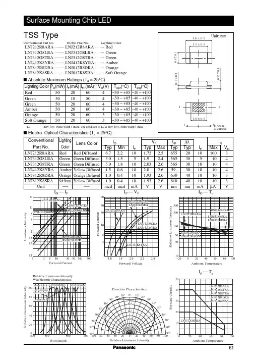
LNJ812R8DRA中文资料
- 格式:pdf
- 大小:31.04 KB
- 文档页数:1

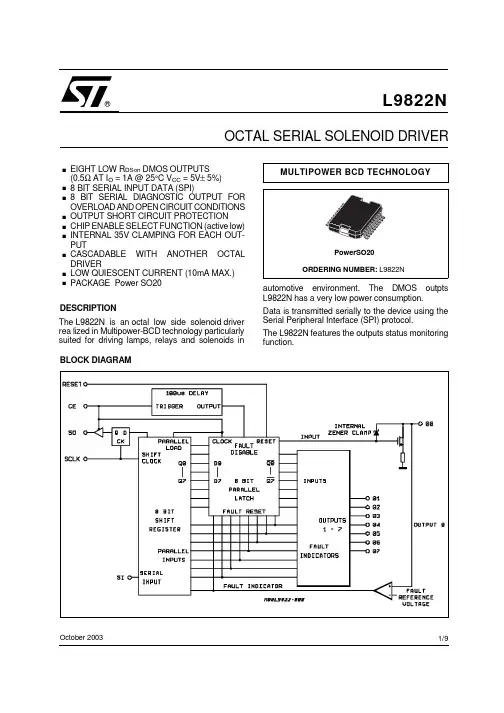
SQ1912AEEH-T1_GE3SQ1912AEEHVishay SiliconixAutomotive Dual N-Channel 20 V (D-S) 175 °C MOSFETMarking Code : 8RFEATURES•TrenchFET ® power MOSFET •AEC-Q101 qualified •100 % R g tested•Typical ESD protection: 800 V•Material categorization:for definitions of compliance please see /doc?99912Notesa.Package limited.b.Pulse test; pulse width ≤ 300 μs, duty cycle ≤ 2 %.c.When mounted on 1" square PCB (FR4 material).PRODUCT SUMMARYV DS (V)20R DS(on) (Ω) at V GS = 4.5 V 0.280R DS(on) (Ω) at V GS = 2.5 V 0.360R DS(on) (Ω) at V GS = 1.8 V 0.450I D (A)0.8ConfigurationDualS OT-363S C-70 Dual (6 lea d s)Top View1S 12G 13D 2D 16G 25S 24ORDERING INFORMATIONPackageSC-70Lead (Pb)-free and Halogen-freeSQ1912AEEH-T1-GE3ABSOLUTE MAXIMUM RATINGS (T C = 25 °C, unless otherwise noted)PA AMETE SYMBOL LIMITUNIT Drain-Source Voltage V DS 20VGate-Source Voltage V GS ± 12Continuous Drain Current aT C = 25 °C I D 0.8A T C = 125 °C0.8Continuous Source Current (Diode Conduction) a I S 0.8Pulsed Drain Current bI DM 3Maximum Power Dissipation bT C = 25 °C P D 1.5W T C = 125 °C 0.5Operating Junction and Storage Temperature RangeT J , T stg-55 to +175°C THERMAL RESISTANCE RATINGSPA AMETE SYMBOL LIMIT UNIT Junction-to-Ambient PCB Mount cR thJA 220°C/WJunction-to-Foot (Drain)R thJF100SQ1912AEEHVishay SiliconixNotesa.Pulse test; pulse width ≤ 300 μs, duty cycle ≤ 2 %.b.Guaranteed by design, not subject to production testing.c.Independent of operating temperature.d.Gate is obscured by ESD network series resistance and cannot be tested directly.Stresses beyond those listed under “Absolute Maximum Ratings” may cause permanent damage to the device. These are stress ratings only, and functional operation of the device at these or any other conditions beyond those indicated in the operational sections of the specifications is not implied. Exposure to absolute maximum rating conditions for extended periods may affect device reliability.SPECIFICATIONS (T C = 25 °C, unless otherwise noted)PA AMETE R SYMBOLTEST CONDITIONS MIN.TYP.MAX.UNITStaticDrain-Source Breakdown Voltage V DS V GS = 0, I D = 250 μA 20--V Gate-Source Threshold Voltage V GS(th)V DS = V GS , I D = 250 μA 0.450.6 1.5Gate-Source LeakageI GSSV DS = 0 V, V GS = ± 4.5 V --± 1μA V DS = 0 V, V GS = ± 12 V--± 10mAZero Gate Voltage Drain Current I DSS V GS = 0 VV DS = 20 V --1μA V GS = 0 V V DS = 20 V, T J = 125 °C --50V GS = 0 V V DS = 20 V, T J = 175 °C--150On-State Drain Current aI D(on)V GS = 4.5 V V DS ≥ 5 V 1.5--A Drain-Source On-State Resistance aR DS(on) V GS = 4.5 V I D = 1.2 A -0.2000.280ΩV GS = 4.5 VI D = 1.2 A, T J = 125 °C --0.423V GS = 4.5 V I D = 1.2 A, T J = 175°C--0.510V GS = 2.5 V I D = 1 A -0.2610.360V GS = 1.8 VI D = 0.2 A-0.3200.450Forward Transconductance b g fs V DS = 10 V, I D = 1.2 A- 2.6-S Dynamic bInput Capacitance C issV GS = 0 V V DS = 10 V, f = 1 MHz -27-pF Output CapacitanceC oss -19-Reverse Transfer Capacitance C rss -7-Total Gate Charge c Q gV GS = 4.5 V V DS = 10 V, I D = 1.2 A -1 1.25nC Gate-Source Charge c Q gs -0.14-Gate-Drain Charge c Q gd -0.27-Gate Resistance d R g f = 1 MHz1.53 4.5k ΩTurn-On Delay Time c t d(on) V DD = 10 V, R L = 20 ΩI D ≅ 0.5 A, V GEN = 4.5 V, R g = 1 Ω-6682ns Rise Time ct r-108135Turn-Off Delay Time c t d(off) -715893Fall Time c t f -390487Source-Drain Diode Ratings and Characteristics bPulsed Current a I SM --3A Forward VoltageV SDI F = 0.5 A, V GS = 0-0.81.2VSQ1912AEEHVishay SiliconixTYPICAL CHARACTERISTICS (25°C, unless otherwise noted)Output CharacteristicsTransconductanceTransfer CharacteristicsOn-Resistance vs. Drain CurrentOn-Resistance vs. Gate-to-Source Voltage Threshold VoltageSQ1912AEEH Vishay SiliconixTYPICAL CHARACTERISTICS(T A = 25 °C, unless otherwise noted)Drain Source Breakdown vs. Junction TemperatureSafe Operating AreaSQ1912AEEH Vishay SiliconixTHERMAL RATINGS(T A = 25 °C, unless otherwise noted)Normalized Thermal Transient Impedance, Junction-to-AmbientNormalized Thermal Transient Impedance, Junction-to-FootNote•The characteristics shown in the two graphs- Normalized Transient Thermal Impedance Junction-to-Ambient (25 °C)- Normalized Transient Thermal Impedance Junction-to-Foot (25 °C)are given for general guidelines only to enable the user to get a “ball park” indication of part capabilities. The data are extracted from single pulse transient thermal impedance characteristics which are developed from empirical measurements. The latter is valid for the part mounted on printed circuit board - FR4, size 1" x 1" x 0.062", double sided with 2 oz. copper, 100 % on both sides. The part capabilities can widely vary depending on actual application parameters and operating conditions.Vishay Silicon ix main tain s worldwide man ufacturin g capability. Products may be man ufactured at on e of several qualified location s. Reliability data for Silicon Technology and Package Reliability represent a composite of all qualified locations. For related documents such as package/tape drawings, part marking, and reliability data, see /ppg?62983.Package InformationVishay Siliconix SCĆ70: 6ĆLEADSAN816Vishay SiliconixDual-Channel LITTLE FOOT R 6-Pin SC-70 MOSFETCopper Leadframe VersionRecommended Pad Pattern and Thermal PerformanceINTRODUCTIONThe new dual 6-pin SC-70 package with a copper leadframe enables improved on-resistance values and enhanced thermal performance as compared to the existing 3-pin and 6-pin packages with Alloy 42 leadframes. These devices are intended for small to medium load applications where a miniaturized package is required. Devices in this package come in a range of on-resistance values, in n-channel and p-channel versions. This technical note discusses pin-outs,package outlines, pad patterns, evaluation board layout, and thermal performance for the dual-channel version.PIN-OUTFigure 1 shows the pin-out description and Pin 1 identification for the dual-channel SC-70 device in the 6-pin configuration.Both n-and p-channel devices are available in this package –the drawing example below illustrates the p-channel device.FIGURE 1.SOT-363SC-70 (6-LEADS)Top ViewS 1G 1D 2D 1G 2S 2For package dimensions see outline drawing SC-70 (6-Leads)(/doc?71154)BASIC PAD PATTERNSSee Application Note 826, Recommended Minimum Pad Patterns With Outline Drawing Access for Vishay Siliconix MOSFET s, (/doc?72286) for the SC-706-pin basic pad layout and dimensions. This pad pattern is sufficient for the low-power applications for which this package is intended. Increasing the drain pad pattern (Figure 2) yields a reduction in thermal resistance and is a preferred footprint.FIGURE 2.SC-70 (6 leads) DualEVALUATION BOARD FOR THE DUAL-CHANNEL SC70-6The 6-pin SC-70 evaluation board (EVB) shown in Figure 3measures 0.6 in. by 0.5 in. The copper pad traces are the same as described in the previous section, Basic Pad Patterns . The board allows for examination from the outer pins to the 6-pin DIP connections, permitting test sockets to be used in evaluation testing.The thermal performance of the dual 6-pin SC-70 has been measured on the EVB, comparing both the copper and Alloy 42 leadframes. This test was then repeated using the 1-inch 2PCB with dual-side copper coating.A helpful way of displaying the thermal performance of the 6-pin SC-70 dual copper leadframe is to compare it to the traditional Alloy 42 version.AN816Vishay SiliconixFIGURE 3.Front of Board SC70-6Back of Board SC70-6D1G2S2S1G1D2SC70−6 DUALTHERMAL PERFORMANCEJunction-to-Foot Thermal Resistance (the Package Performance)Thermal performance for the dual SC-70 6-pin package is measured as junction-to-foot thermal resistance, in which the “foot” is the drain lead of the device as it connects with the body. The junction-to-foot thermal resistance for this device is typically 80_C/W, with a maximum thermal resistance of approximately 100_C/W. This data compares favorably with another compact, dual-channel package – the dual TSOP-6 –which features a typical thermal resistance of 75_C/W and a maximum of 90_C/W.Power DissipationThe typical R θJA for the dual-channel 6-pin SC-70 with a copper leadframe is 224_C/W steady-state, compared to 413_C/W for the Alloy 42 version. All figures are based on the 1-inch 2 FR4 test board. The following example shows how the thermal resistance impacts power dissipation for the dual 6-pin SC-70 package at varying ambient temperatures.Alloy 42 Leadframedevices in the 6-pin SC-70 dual-channel configuration will handle power dissipation in excess of 0.5 W.TESTINGTo further aid the comparison of copper and Alloy 42leadframes, Figures 4 and 5 illustrate the dual-channel 6-pin SC-70 thermal performance on two different board sizes and pad patterns. The measured steady-state values of R θJA for the dual 6-pin SC-70 with varying leadframes are as follows:LITTLE FOOT 6-PIN SC-70Alloy 42Copper1) Minimum recommended pad pattern on the EVB board (see Figure 3).518_C/W 344_C/W 2) Industry standard 1-inch 2 PCB with maximum copper both sides.413_C/W224_C/WThe results indicate that designers can reduce thermal resistance (θJA) by 34% simply by using the copper leadframe device as opposed to the Alloy 42 version. In this example, a 174_C/W reduction was achieved without an increase in board area. If an increase in board size is feasible, a further 120_C/W reduction can be obtained by utilizing a 1-inch 2. PCB area.The Dual copper leadframe versions have the following suffix:Dual:Si19xxEDH Compl.:Si15xxEDHAN816Vishay SiliconixDocument Number: 7140512-Dec-033Time (Secs)FIGURE 4.Dual SC70-6 Thermal Performance on EVB T h e r m a l R e s i s t a n c e (C /W )0150010020010010003001010-110-210-310-410-5400Time (Secs)FIGURE 5.Dual SC70-6 Comparison on 1-inch 2 PCBT h e r m a l R e s i s t a n c e (C /W )0150010020010010003001010-110-210-310-410-5400Application Note 826Vishay Siliconix Document Number: 7260218Revision: 21-Jan-08A P P L I C A T I O N N O T ERECOMMENDED MINIMUM PADS FOR SC-70: 6-LeadLegal Disclaimer Notice VishayDisclaimerALL PRODU CT, PRODU CT SPECIFICATIONS AND DATA ARE SU BJECT TO CHANGE WITHOU T NOTICE TO IMPROVE RELIABILITY, FUNCTION OR DESIGN OR OTHERWISE.Vishay Intertechnology, Inc., its affiliates, agents, and employees, and all persons acting on its or their behalf (collectively,“Vishay”), disclaim any and all liability for any errors, inaccuracies or incompleteness contained in any datasheet or in any other disclosure relating to any product.Vishay makes no warranty, representation or guarantee regarding the suitability of the products for any particular purpose or the continuing production of any product. To the maximum extent permitted by applicable law, Vishay disclaims (i) any and all liability arising out of the application or use of any product, (ii) any and all liability, including without limitation special, consequential or incidental damages, and (iii) any and all implied warranties, including warranties of fitness for particular purpose, non-infringement and merchantability.Statements regarding the suitability of products for certain types of applications are based on Vishay’s knowledge of typical requirements that are often placed on Vishay products in generic applications. Such statements are not binding statements about the suitability of products for a particular application. It is the customer’s responsibility to validate that a particular product with the properties described in the product specification is suitable for use in a particular application. Parameters provided in datasheets and / or specifications may vary in different applications and performance may vary over time. All operating parameters, including typical parameters, must be validated for each customer application by the customer’s technical experts. Product specifications do not expand or otherwise modify Vishay’s terms and conditions of purchase, including but not limited to the warranty expressed therein.Except as expressly indicated in writing, Vishay products are not designed for use in medical, life-saving, or life-sustaining applications or for any other application in which the failure of the Vishay product could result in personal injury or death. Customers using or selling Vishay products not expressly indicated for use in such applications do so at their own risk. Please contact authorized Vishay personnel to obtain written terms and conditions regarding products designed for such applications.No license, express or implied, by estoppel or otherwise, to any intellectual property rights is granted by this document or by any conduct of Vishay. Product names and markings noted herein may be trademarks of their respective owners.© 2019 VISHAY INTERTECHNOLOGY, INC. ALL RIGHTS RESERVEDRevision: 01-Jan-20191Document Number: 91000SQ1912AEEH-T1_GE3。

®OCTAXIAL CONTACTSEthernet, SuperSpeed USB, HDMI, DisplayPort, SATAFEBRUARY 2018For Series 23 SuperNine ®, Series 80 Mighty Mouse, Series 28HiPer-D ®, Series 791, Series 792, ARINC 600 and EPXB Connectors®Glenair, Inc.1211 Air WayGlendale, CA 91201-2497818-247-6000*****************High-speed octaxial contacts for Ethernet, SuperSpeed USB and multi-gigabit datalinksHIGH-SPEED CONTACT TECHNOLOGYEl Ochito ® WhiteEl Ochito ® BlueEl Ochito ® Red10G Ethernet 1000BASE-T 10GBASE-TSuperSpeed USB 3.0HDMI SATA DisplayPortHigh speed, harsh environment El Ochito®octaxial contacts save size and weight. Suitable for aircraft avionics, weapons systems, satellites, radars,communications equipment and other aerospace/defense gear,El Ochito® contacts are optimized for 10G Ethernet, SuperSpeed USB and other multi-gigabit datalink protocols including HDMI, DisplayPort and SATA.El Ochito Type II Contacts24-26 AWG, Serviceable, Threaded Wire Shield Termination, Integral Contact Release Sleeve© 2018 Glenair, Inc • 1211 Air Way, Glendale, CA 91201 • 818-247-6000 • • U.S. CAGE code 06324 • El Ochito ® Octaxial ContactsDimensions in Inches (millimeters) are subject to change without notice.1000BASE-T, 10GBASE-TSuperSpeed USBHDMI, DisplayPort, SATAData Pair IsolatorData Pair IsolatorFront InsulatorFront InsulatorOuter BodyOuter BodyAlignment KeyAlignment KeyContact Organizer InsulatorContact Organizer InsulatorSocket ContactsPin Contacts SleeveDielectric SleeveType I Pin Contact Type I Socket ContactData Pair Isolator Data Pair IsolatorFront InsulatorFront InsulatorOuter BodyOuter BodyAlignment KeyAlignment KeyContact Release SleeveContact Release SleeveContact Organizer InsulatorContact Organizer InsulatorSocket ContactsPin ContactsRetainer NutRetainer NutO-ringO-ringHeatshrink TubeHeatshrink TubeInner FerruleInner FerruleType II Socket Contact10GBASE-T El Ochito®SuperSpeed USBSATAEl Ochito®Red859-134(GS206)© 2018 Glenair, Inc • 1211 Air Way, Glendale, CA 91201 • 818-247-6000 • • U.S. CAGE code 06324 • El Ochito®Octaxial Contacts© 2018 Glenair, Inc • 1211 Air Way, Glendale, CA 91201 • 818-247-6000 • • U.S. CAGE code 06324 • El Ochito ® Octaxial Contacts Dimensions in Inches (millimeters) are subject to change without notice.5DimensionsEl Ochito ® Type I Pin Contact 858-003, 858-016, 858-028, and 858-030.920(23.37) MAXØ .276/.271(7.01/6.88).060 (1.52).033/.029 (0.84/0.74).305/.295(7.75/7.49)858-003, 858-028-01: .231 (5.87) HEX858-016, 858-028-02, 858-030: .265 (6.73) ROUNDØ .316/.313(8.03/7.95)Ø .219/.217(5.56/5.51)POLARIZATIONKEYPIN NO. DESIGNATION (NOT MARKED ONPART)CABLE (REF)12345678 SHIELD CRIMP FERRULEEl Ochito ® Type II Pin Contact 858-0051.625 (41.28) MAX Ø .316/.313(8.03/7.95)Ø .219/.217(5.56/5.51)CABLE (REF)HEATSHRINKTUBING.033/.029 (0.84/0.74).305/.295(7.75/7.49).060 (1.52)POLARIZATIONKEYPIN NO. DESIGNATION (NOT MARKED ON PART)12345678.313 (7.95) FLATS.320 (8.13) HEXINTEGRAL RELEASE SLEEVESHIELDRETAINER NUTEl Ochito ® Type II Socket Contact 858-0061.950 (49.53) MAX Ø .316/.313(8.03/7.95)CABLE (REF)HEATSHRINKTUBING.033/.029 (0.84/0.74).060 (1.52)POLARIZATIONKEY PIN NO. DESIGNATION (NOT MARKED ON PART)12345678.320 (8.13) HEXINTEGRAL RELEASE SLEEVE.313 (7.95) FLATSØ .288/.284(7.32/7.21).631/.625 (16.02/15.88)SHIELDRETAINER NUTEl Ochito ® Type I Socket Contact 858-004, 858-017, 858-029, and 858-031.770(19.56)MAX .033/.029(0.84/0.74).631/.625(16.02/15.88)POLARIZATIONKEYØ .288/.284(7.32/7.21)Ø .316/.313(8.03/7.95)Ø .276/.271(7.01/6.88)SHIELD CRIMP FERRULE 858-004, 858-029-01: .231 (5.87) HEX858-017, 858-029-02, 858-031: .265 (6.73) ROUNDCABLE (REF).060 (1.52)PIN NO. DESIGNATION (NOT MARKED ONPART)12345678®Octaxial Contacts6© 2018 Glenair, Inc • 1211 Air Way, Glendale, CA 91201 • 818-247-6000 • • U.S. CAGE code 06324 • El Ochito ® Octaxial ContactsDimensions in Inches (millimeters) are subject to change without notice.El Ochito ® Pin Contact 858-009 for ARINC 600 Connectors.515/.505(13.08/12.83)POLARIZATIONKEY.90(22.9) MAX.033/.029 (0.84/0.74)Ø .316/.313(8.03/7.95)Ø .219/.217(5.56/5.51)Ø .276/.271(7.01/6.88).075/.073(1.91/1.85)SHIELD CRIMP858-009-01F: .231 (5.87) HEX 858-009-02F: .265 (6.73) ROUNDPIN NO. DESIGNATION (NOT MARKED ONPART)12345678DimensionsEl Ochito ® Socket Contact 858-010 for ARINC 600 ConnectorsØ .276/.271(7.01/6.88)CABLE (REF).90(22.9)MAX .033/.029(0.84/0.74).600/.590 (15.24/15.00)SHIELD CRIMP858-010-01F: .231 (5.87) HEX 858-010-02F: .265 (6.73) ROUNDPOLARIZATIONKEYØ .288/.284(7.32/7.21)Ø .316/.313(8.03/7.95)PIN NO. DESIGNATION (NOT MARKED ONPART)12345678.075/.073(1.91/1.85)El Ochito ® Pin Contact 858-014 for EN4644 EPXB Connectors.760(19.30) MAXØ .276/.273(7.01/6.93).075/.073(1.91/1.85).033/.029 (0.84/0.74).053/.043 (1.35/1.09).515/.505 (13.08/12.83)SHIELD CRIMP .231 (5.87) HEXØ .316/.313(8.03/7.95)Ø .219/.217(5.56/5.51)POLARIZATIONKEYPIN NO. DESIGNATION (NOT MARKED ONPART)CABLE (REF)12345678El Ochito ® Socket Contact 858-015 for EN4644 EPXB ConnectorsØ .276/.273(7.01/6.53)CABLE (REF).620(15.75)MAX .033/.029(0.84/0.74).600/.590 (15.24/15.00).034/.020 (0.86/0.51)SHIELD CRIMP .231 (5.87) HEXPOLARIZATIONKEYØ .288/.284(7.32/7.21)Ø .316/.313(8.03/7.95)PIN NO. DESIGNATION (NOT MARKED ONPART)12345678.075/.073(1.91/1.85)El Ochito ® Socket Contact 858-032 for Series 791 and 792 Connectors.975 (24.77) MAX.289/.279 (7.34/7.09)POLARIZATIONKEYØ .288/.284(7.32/7.21)Ø .316/.313(8.03/7.95)Ø .276/.271(7.01/6.88) SHIELD CRIMP858-032-01: .231 (5.87) HEX 858-032-02: .265 (6.73) ROUNDCABLE (REF).060 (1.52)PIN NO. DESIGNATION (NOT MARKED ONPART)12345678®Octaxial Contacts© 2018 Glenair, Inc • 1211 Air Way, Glendale, CA 91201 • 818-247-6000 • • U.S. CAGE code 06324 • El Ochito ® Octaxial ContactsDimensions in Inches (millimeters) are subject to change without notice.724 AWG S/UTP Cat 6A CableGlenair Part Number 963-037-24Manufacturer Part Number E6A3824ManufacturerPICS/UTP 24 AWG cable is specially designed for airborne 10 Gigabit Ethernet applications. Twisted pairs are separated by a fluoropolymer spline for reduced crosstalk and attenuation. This 200°C rated cable is Skydrol resistant, RoHS compliant and meets FAA FAR Parts 23 and 25 Appendix F flammability requirements. Laser-markable white PTFE jacket withstands abrasion and chemicals. Meets ANSI/TIA-568-C.2 Category 6A performance up to 246 feet.Construction DetailsCONDUCTOR24 AWG 19X36 SILVER PLATED COPPERFOUR TWISTED PAIRSPFA WIRE INSULATIONPTFE TAPE FLUOROPOLYMER SPLINE SILVER-PLATED COPPER BRAID90% MIN. COVERAGEFOIL SHIELD100% COVERAGEJACKETPTFE WHITE LASER-MARKABLE 0.26 (6.6) NOMINALColor CodePair #1 Blue, White/Blue · Pair #2 Orange, White/Orange · Pair #3 Green, White/Green · Pair #4 Brown, White/BrownSpecificationsImpedance (ohms)100Temperature Rating -55 to +200°CWeight (lbs/100 ft.) 4.6 Capacitance (pF/ft)14.5Minimum Bend Radius (inches).78Velocity of Propagation %70Dielectric Voltage Rating (kV rms) 1.5DC Resistance, Max (ohms/1000 ft.)28.5Max Distance in Feet (m)246 (75)Attenuation Nom / MaxFrequency dB/100 ft.10 MHz2.3 / 2.6100 MHz 7.0 / 8.4250 MHz 11.4/ 13.7500 MHz16.5 / 20.024 AWG S/FTP Cat 6A CableGlenair Part Number 963-033-24Manufacturer Part Number RCN9034-24ManufacturerGoreS/FTP 24 AWG cable has an individual foil shield around each data pair for reduced crosstalk and attenuation. This high data rate Ethernet cable features a unique cable jacket material and high-density construction that significantly reduces weight and diameter. Meets ANSI/TIA 568-C.2 Category 6A requirements up to 80 meters (262 feet). Qualified to SAE AS6070/5-24.Construction DetailsCONDUCTOR24 AWG 19X36 SILVER PLATED COPPER ALLOYWIRE INSULATION ePTFE / PTFE .060 (1.52)OVERALL SHIELDAWG 40 SILVER-PLATED COPPER 92% MIN COVERAGEPAIR SHIELDALUMINIZED POLYAMIDE (ALUMINUM OUT)FILLERFEP/ePTFE .060 (1.52) DIA.JACKETENGINEERED FLUOROPOLYMER EF100WHITE LASER-MARKABLE 0.004 (0.10) WALL 0.260 (6.60) MAX DIAMETERColor CodePair #1 Blue, White/Blue · Pair #2 Orange, White/Orange · Pair #3 Green, White/Green · Pair #4 Brown, White/BrownSpecificationsImpedance (ohms)100 (+10 -5)Temperature Rating -65 to +200°CWeight (lbs/100 ft.) 4.1 Capacitance (pF/ft)12.5Time Delay1.24 ns/ftMaximum Attenuation at 80m LengthFrequency dB 10 MHz 5.9100 MHz 19.1250 MHz 31.1500 MHz 45.3NEXT (minimum)Frequency dB 1 MHz 74.310 MHz 59.2100 MHz 52.3250 MHz 47.9500 MHz 42.224 AWG Category 6A Ethernet Cables 963-037 and 963-033®Octaxial Contacts8© 2018 Glenair, Inc • 1211 Air Way, Glendale, CA 91201 • 818-247-6000 • • U.S. CAGE code 06324 • El Ochito ® Octaxial ContactsDimensions in Inches (millimeters) are subject to change without notice.26 AWG S/UTP Cat 6A CableGlenair Part Number963-003-26Manufacturer Part Number E6A3826Manufacturer PICS/UTP 26 AWG cable is small, lightweight and flexible. Twisted pairs are separated by a fluoropolymer spline for reduced crosstalk and attenuation. This 200°C rated cable is Skydrol resistant, RoHS compliant and meets FAA FAR Parts 23 and 25 Appendix F flammability requirements. Rugged, laser-markable PTFE jacket withstands abrasion and chemicals. Meets ANSI/TIA-568-C.2 Category 6A performance up to 193 feet.Construction DetailsCONDUCTOR26 AWG 19X38 SILVER PLATED HIGH STRENGTH COPPER ALLOYFOUR TWISTED PAIRSPFA WIRE INSULATIONFLUOROPOLYMER TAPE SPLINEFLUOROPOLYMERSILVER-PLATED COPPER BRAID80% MIN. COVERAGEJACKETPTFE WHITE LASER-MARKABLE 0.22 (5.59)Color CodePair #1 Blue, White/Blue · Pair #2 Orange, White/Orange · Pair #3 Green, White/Green · Pair #4 Brown, White/BrownSpecificationsImpedance (ohms)100Temperature Rating -55 to +200°CWeight (lbs/100 ft.) 3.5 Capacitance (pF/ft)14.5Minimum Bend Radius (inches)0.66Velocity of Propagation %70Dielectric Voltage Rating (kV rms) 1.5DC Resistance, Max (ohms/1000 ft.)44.8Max Distance in Feet (m)193 (59)Attenuation Nom / MaxFrequency dB/100 ft.10 MHz2.7 /3.1100 MHz 8.7 / 10.5250 MHz 14.4 / 17.2500 MHz20.7 / 24.926 AWG S/FTP Cat 6A CableGlenair Part Number963-033-26Manufacturer Part Number RCN9047-26Manufacturer GoreS/FTP 26 AWG cable has an individual foil shield around each data pair for reduced crosstalk and attenuation. This high data rate Ethernet cable features a unique cable jacket material and high-density construction that significantly reduces weight and diameter. Meets ANSI/TIA 568-C.2 Category 6A requirements up to 65 meters (213 feet). Qualified to SAE AS6070/6-6.Construction DetailsCONDUCTOR26 AWG 19X38 SILVER PLATED HIGH STRENGTH COPPER ALLOYWIRE INSULATION ePTFE / PTFE .050 (1.27)OVERALL SHIELDAWG 40 SILVER-PLATED COPPER 92% MIN COVERAGEPAIR SHIELDALUMINIZED POLYAMIDE (ALUMINUM OUT)FILLERePTFEJACKETENGINEERED FLUOROPOLYMER EF100WHITE LASER-MARKABLE 0.004 (0.10) WALL 0.220 (5.59) MAX DIAMETERColor CodePair #1 Blue, White/Blue · Pair #2 Orange, White/Orange · Pair #3 Green, White/Green · Pair #4 Brown, White/BrownSpecificationsImpedance (ohms)100 (+10 -5)Temperature Rating -65 to +200°CWeight (lbs/100 ft.) 3.2 Capacitance (pF/ft)12.5Time Delay1.24 ns/ftMaximum Attenuation at 65m LengthFrequency dB 10 MHz 5.9100 MHz 19.1250 MHz 31.1500 MHz 45.3NEXT (minimum)Frequency dB 1 MHz 74.310 MHz 59.2100 MHz 52.3250 MHz 47.9500 MHz 42.226 AWG Category 6A Ethernet Cables 963-003 and 963-033© 2018 Glenair, Inc • 1211 Air Way, Glendale, CA 91201 • 818-247-6000 • • U.S. CAGE code 06324 • El Ochito ® Octaxial Contacts Dimensions in Inches (millimeters) are subject to change without notice.926 AWG S/FTP Cat 6A CableGlenair Part Number963-050Manufacturer Part Number RCN8966-26Manufacturer Gore963-050 is similar to 963-033-26 except with two layer wire insulation compatible with insulation displacement Ethernet connectors. An individual foil shield around each data pair provides reduced crosstalk and attenuation. Meets ANSI/TIA 568-C.2 Category 6A requirements up to 65 meters (213 feet).Construction DetailsCONDUCTOR26 AWG 19X38 SILVER PLATED HIGH STRENGTH COPPER ALLOYWIRE INSULATION ePTFE OVER PTFE .050 (1.27) MAX OVERALL SHIELDAWG 40 SILVER-PLATED COPPER 92% MIN COVERAGEPAIR SHIELDALUMINIZED KAPTON (ALUMINUM OUT)FILLERFEP / ePTFEJACKETENGINEERED FLUOROPOLYMER EF100WHITE LASER-MARKABLE 0.003 (0.08) WALL 0.230 (5.84) MAX DIAMETERColor CodePair #1 Blue, White/Blue · Pair #2 Orange, White/Orange · Pair #3 Green, White/Green · Pair #4 Brown, White/BrownSpecificationsImpedance (ohms)100 (+10 -5)Temperature Rating -55 to +200 °CWeight (lbs/100 ft.) 3.5 Operating Voltage150 VrmsMaximum Attenuation at 65mLengthFrequency dB 10 MHz 5.9100 MHz 19.1250 MHz 31.1500 MHz 45.3NEXT (minimum)Frequency dB 1 MHz 74.310 MHz 59.2100 MHz 52.3250 MHz 47.9500 MHz 42.226 AWG Category 6A Ethernet Cable 963-05010© 2018 Glenair, Inc • 1211 Air Way, Glendale, CA 91201 • 818-247-6000 • • U.S. CAGE code 06324 • El Ochito ® Octaxial ContactsDimensions in Inches (millimeters) are subject to change without notice.SuperSpeed USB CableGlenair Part Number 963-04790 ohm aerospace-grade cable features abrasion-resistant polyurethane jacket and #24 AWG wires for USB power. SuperSpeed data pairs feature low dielectric constant closed cell foam insulation. Each SuperSpeed pair has an aluminized polyester shield.Construction DetailsSUPERSPEED PAIRS90 OHM SHIELDED TWISTEDCONDUCTORS - 26 AWG 19X38 SILVER PLATED COPPERINSULATION - LOW LOSS FOAMED DIELECTRIC INSULATION .041 (1.04)DRAIN - 28 AWG 19X40 SILVER PLATED COPPERSHIELD - AL/POLYESTER,100% COVERAGE, FOIL SIDE INOVERALL SHIELD AWG 40 SILVER-PLATED COPPER 90% MIN COVERAGE POWER PAIRAWG 24 SILVER-PLATED COPPER FEP INSULATION RED/BLACKUTP SIGNAL PAIR90 OHM UNSHIELDED TWISTED 26 AWG 19X38 SILVER PLATEDCOPPER, FEP INSULATION, .037 (0.94)JACKETBLACK POLYURETHANE .237 (6.02)Color CodeSuperSpeed pairs VIO/ORN and BLU/YEL · Power wires RED, BLK · Low speed pair WHT/GRN.SpecificationsImpedance (ohms) High speed pairs Low-speed pair 90 ± 590 ±10Temperature Rating-30 to +105°CVoltage Rating (DWV Vac)300Frequency (GHz)IL (dB/m)NEXT (dB)1.25 1.874.62.5 2.667.75.0 4.053.17.55.753.5High Temperature SuperSpeed USB CableGlenair Part Number 963-110High performance, high temperature cable delivers dependable signal integrity over longer cable lengths. Fluoropolymer jacket can be laser-marked. Low-skew SuperSpeed data pairs have individual braid shields.Construction DetailsSUPERSPEED PAIRS90 OHM SHIELDED TWISTEDCONDUCTORS - 26 AWG 19X38 SILVER PLATED COPPERINSULATION - PTFE OVER ePTFE BINDER - WHITE ePTFEDRAIN - 28 AWG 19X40 SILVER PLATED COPPERSHIELD - 40 AWG SILVER PLATED COPPER BRAIDJACKET - FLUOROPOLYMER, WHITEOUTER SHIELD BINDER - ePTFE UNDER AND OVERAWG 40 SILVER-PLATED COPPER BRAIDPOWER PAIRAWG 24 19/36 SILVER-PLATED COPPER FLUOROPLASTIC INSULATION RED/BLACK TWISTEDUTP SIGNAL PAIR90 OHM UNSHIELDED TWISTED26 AWG 19X38 SILVER PLATED COPPER, FLUOROPLASTIC INSULATIONJACKETFLUOROPOLYMER, NATURAL OVER FLUOROPOLYMER, WHITELASER-MARKABLE .228/.244 (5.8/6.2) DIA.Color CodeSuperSpeed pairs VIO/ORN and BLU/YEL · Power wires RED, BLK · Low speed pair WHT/GRN.SpecificationsImpedance (ohms)90 ± 5Temperature Rating -65 to +200°C Voltage Rating< 50 Vac Dielectric Withstanding Voltage 100 Vac rms Weight57 g/m nominal Attenuation (S0021)Freq. (GHz)dB/m max..625 1.21.25 1.72.5 2.55.0 3.97.5 5.0SuperSpeed USB Cables 963-047 and 963-110© 2018 Glenair, Inc • 1211 Air Way, Glendale, CA 91201 • 818-247-6000 • • U.S. CAGE code 06324 • El Ochito ® Octaxial ContactsDimensions in Inches (millimeters) are subject to change without notice.NEXT (dB)MHz 0250500ACR-F (dB)MHz 0250500ACR-N (dB)MHz 0250500NEXT (dB)MHz 0204060801000250MHz0250500ACR-F (dB)MHz 0204060801000250ACR-F @ Remote (dB)MHz250500ACR-N (dB)MHz -40040800250ACR-N @ Remote (dB)MHz250500Insertion Loss (dB)MHz 0250500ACR-N @ Remote (dB)MHz250500RL @ Remote (dB)MHz 0250500ACR-N (dB)MHz250500ACR-N @ Remote (dB)MHz250500RL (dB)MHz 1000250500RL @ Remote (dB)MHz 250500* Measurement is within the accuracy limits of the instrument.FLUKE DSX-5000MAINFLUKE DSX-5000REMOTE© 2018 Glenair, Inc • 1211 Air Way, Glendale, CA 91201 • 818-247-6000 • • U.S. CAGE code 06324 • El Ochito ® Octaxial ContactsDimensions in Inches (millimeters) are subject to change without notice.SuperSpeed Pair 1USB 3.1 Gen 1 Upper Limit USB 3.1 Gen 1 Lower LimitSuperSpeed Pair 240050060070080090010001100120013001400Time (ps)Test BoardPC Tail Mated Contacts Crimp Area Cable0.3m 1.5m 1.8m USB 3.1 Gen 1 Limit2468Frequency (GHz)NEXT (SuperSpeed Pairs)El Ochito Blue Cable Assembly0-100-20-30-40-50-60-70-800.3m SS10.3m SS21.5m SS11.5m SS21.8m SS11.8m SS2USB 3.1 Gen 1 Limit2468Frequency (GHz)2 mated contacts}2 mated contacts}3 mated contacts }2468Frequency (GHz)NEXT (SuperSpeed to D+/D-)El Ochito ® Blue Cable Assembly0-100-20-30-40-50-60-70-80S (d B )0.3m 1.5m 1.8m USB 3.1 Gen 1 Limit2468Frequency (GHz)FEXT (SuperSpeed to D+/D-)El Ochito ® Blue Cable Assembly0-100-20-30-40-50-60-70-800.3m 1.5m 1.8m USB 3.1 Gen 1 Limit2468Frequency (GHz)Mode Conversion (SCD21)El Ochito ® Blue Cable Assembly-10-20-30-40-50-60-70-80B )0.3m SS10.3m SS21.5m SS11.5m SS2USB 3.1 Gen 1 Limit 1.8m SS11.8m SS2El Ochito® Blue for SuperSpeed USB, pin contact mating faceContact PositionsEl Ochito® Blue for SuperSpeed USB, pin contact mating faceContact Positions®Octaxial ContactsEl Ochito ® Blue-to-SuperSpeed USB Cable Assemblies 8572-0003Wiring Diagram 8572-0003-01El Ochito ® Pin to USB 3.0 A PlugWiring Diagram 8572-0003-04El Ochito ® Socket toUSB 3.0 Micro-B PlugWiring Diagram 8572-0003-02El Ochito ® Socket to USB 3.0 A RecepWiring Diagram 8572-0003-03El Ochito ® Socket to USB 3.0 B Plug8572-0003-01-(XX)OCHITO PIN CONTACT USB 3.0TYPE A PLUG876544321WHT GRN YEL BLU BLK REDVIO DRAIN WIRESORNGND23951768VBUS D-D+GND RX-RX+GND TX-TX+8572-0003-02-(XX)OCHITO SOCKET CONTACT USB 3.0TYPE A RECEP876544321WHT GRN YEL BLU BLK REDVIO DRAIN WIRESORNGND23951768VBUS D-D+GND RX-RX+GND TX-TX+8572-0003-03-(XX)OCHITO SOCKET CONTACT USB 3.0TYPE B PLUG876544321WHT GRN YEL BLU BLK REDVIO DRAIN WIRESORNGND23951768VBUS D-D+GND RX-RX+GND TX-TX+8572-0003-04-(XX)OCHITO SOCKET CONTACT USB 3.0MICRO-B PLUG876545321WHT GRN YEL BLU BLK REDVIO DRAIN WIRESORNGND231061879VBUS D-D+GND RX-RX+GND TX-TX+Plug Adapter Receptacle Adapter®Octaxial ContactsOverall Length Part Number Inches meters 180.45858-020-A-02-18360.91858-020-A-02-3672 1.82858-020-A-02-72120 3.05858-020-A-02-120859-117P Pin AdapterShell SizeA Diameter 1.200 (30.5) MAXØ AHBCDFEGAAGFEDCB HIn.mm.09 (A).65016.511 (B).78019.817 (E) 1.20330.619 (F) 1.26532.121 (G) 1.39035.323 (H) 1.52038.625 (J)1.63541.5859-132P Pin AdapterShell SizeA Diameter 1.200 (30.5) MAX Ø AAG FEDC B HIn.mm.09 (A).71018.011 (B).85021.617 (E) 1.27132.319 (F) 1.33333.921 (G) 1.46037.123 (H) 1.58540.325 (J)1.71143.5859-118S Socket AdapterShell SizeA Diameter 1.200 (30.5) MAXØ AH B D FEG AIn.mm.09 (A).71018.011 (B).85021.617 (E) 1.27132.319 (F) 1.33333.921 (G) 1.46037.123 (H) 1.58540.325 (J)1.71143.5859-133S Socket AdapterShell SizeA Diameter 1.200 (30.5) MAXØ AHBC DFEGAAHGFEDCBIn.mm.09 (A).65016.511 (B).78019.817 (E) 1.20330.619 (F) 1.26532.121 (G) 1.39035.323 (H) 1.52038.625 (J)1.63541.5Overall Length Part Number Inches meters 180.45858-020-B-02-18360.91858-020-B-02-3672 1.82858-020-B-02-72120 3.05858-020-B-02-120El Ochito ® Test Jumpers with Pin ContactsOCHITO PIN CONTACT (858-018)ETHERNET CABLE S/FTP CAT6A, 26 AWG(963-033-26)RJ45 MODULAR PLUGSHIELDED HIGH PERFORMANCECAT6A 10 GIGABIT SPEEDPin Jumper Ordering InformationEl Ochito® Test Jumper SchematicNotes1.858-020 jumper cables are intended only for use in Glenair El Ochito® test adapters. Do not attempt to install in MIL-DTL-38999 type connectors.2. Other cable lengths are readily available. Change the suffix number to the desired length in inches.3. 858-020 jumper cables are fully assembled and 100% electrically tested.4. Length is minimum overall length including contact and plug.5. No tool is required to install or remove contacts.6.Jumper cables are wired per the guidelines of ARINC 664 Part 2 Appendix N.El Ochito ® Test Jumpers with Socket ContactsOCHITO SOCKETCONTACT (858-019)RJ45 MODULAR PLUGSHIELDED HIGH PERFORMANCECAT6A 10 GIGABIT SPEEDETHERNET CABLE S/FTP CAT6A, 26 AWG(963-033-26)Socket Jumper Ordering InformationMATING FACE OF SOCKETCONTACT1234567816782345MATING FACE OF PINCONTACT8763214587654321BRNWHT/BRN BLUE WHT/BLU ORN WHT/ORN GRN WHT/GRN OCHITO PIN OR SOCKETRJ-45El Ochito ® Test Adapters and Jumpers for SuperNine ® ConnectorsInner Contacts (8)Ferrule BushingInner and Outer InsulatorsOuter BodyMounting BlockQ Q QQQ Q QQ Q Q Q QQQQQQQQQQQADDITIONAL RUGGEDIZEDHIGH-SPEED DATALINK SOLUTIONSavailable now from GlenairSUPERSEAL™ IP67 OPEN-FACE RUGGEDIZED FIELD RJ45 SOLUTIONSSUPERSEAL™ IP67 OPEN-FACE RUGGEDIZED FIELD USB 2.0 AND 3.0 SOLUTIONSSeries ITS 5015 type SuperSeal™ RJ45MIL-DTL-28840 type SuperSeal™ RJ45MIL-DTL-38999 Sr. III type SuperSeal™ RJ45Series IPT 26482 typeSuperSeal™ RJ45Series 80 Mighty MouseSuperSeal™ RJ45Series 80 Mighty MouseSuperSeal™ USB Series IPT 26482 typeSuperSeal™ USB MIL-DTL-38999 Sr. III type SuperSeal™ USB MIL-DTL-28840 type SuperSeal™ USBSeries ITS 5015 type SuperSeal™ USBOCTOBYTE™ SERIES RUGGEDIZED ETHERNET CONNECTOR SPEED-MASTER™ 10G+ ETHERNETEthernet Cat7A contacts Ethernet Cat5 contacts Coax contacts Ethernet MVB - WBT contactsSpeed-Master™ modular 10G+ Ethernet technology (shown here in SuperNine®packaging) available now for22D gage contacts and wiresTested for compliance according to EN50173-1 standards for CAT5E and CAT7HIGH-SPEED / RF DATALINK CONTACTSSize #8 differential twinax contactsSize #12 ultra-twinax differential twinaxcontactsSize #8 quadrax contacts Size #12 SMPM type spring-loaded coaxialSize #8 spring-loaded BMB microwave contacts GLENAIR FIBER OPTIC INTERCONNECT SOLUTIONSMIL-DTL-38999 type fiber optic Glenair Front Release (GFR)fiber opticNGCON MIL-PRF-64266fiber optics Eye-Beam™ GLT and GMAexpanded beamMT Ferrule 38999 typefiber optic ARINC 801 type fiber opticGlenair High Density (GHD) fiber optic29© 2018 Glenair, Inc • 1211 Air Way, Glendale, CA 91201 • 818-247-6000 • • U.S. CAGE code 06324 • High-Speed ContactsLaboratory link test and qualification data for harsh-environment Photonic solutions areavailable—just contact the factorySignal aggregation media converter(cutaway view)7-port Ethernet switchSmall form-factor bi-directionalPCB-mount transceivers Lightning-strike protected ARINC 801 F/O to D38999-type media converter Micro-aggregatorD38999 type fiber optic Ethernet media converter DVI copper-to-fiber media converterPCB-mount dual Transmitters, Receivers, and Transceivers RF-over-fiber for SATCOM-based WiFiand IFE systemsAEROSPACE-GRADE TRANSCEIVERS, RECEIVERS, AND MEDIA CONVERTERSSERIES 050 OVERVIEWRuggedized, Small Form-Factor Photonic Interconnect SolutionsEvaluation boards and performance testing available for all systemsGlenair, Inc.1211 Air Way • Glendale, California • 91201-2497Telephone:818-247-6000•Fax:818-500-9912•*****************Telephone:+44-1623-638100Facsimile:+44-1623-638111****************.uk Glenair UK Ltd40 Lower Oakham Way Oakham Business Park Mansfield, Notts NG18 5BY England Telephone:06172 / 68 16 0Facsimile:06172 / 68 16 90***************Glenair GmbH Schaberweg 2861348 Bad Homburg GermanyTelephone:+33-5-34-40-97-40Facsimile:+33-5-61-47-86-10****************Glenair France SARL 7, Avenue Parmentier Immeuble Central Parc #231200 Toulouse FranceTelephone:847-679-8833Facsimile:847-679-8849Glenair Microway Systems 7000 North Lawndale Avenue Lincolnwood, IL 60712Telephone:+46-8-50550000****************Glenair Nordic ABGustav III : S Boulevard 46SE-169 27 Solna Sweden© 2018 Glenair, Inc. Printed in U.S.A.CAT-159Telephone:+34-925-89-29-88Facsimile:+34-925-89-29-87****************Glenair Iberica C/ La Vega, 1645612 Velada SpainTelephone:203-741-1115Facsimile:203-741-0053*****************Glenair Power Products Group 20 Sterling Drive Wallingford, CT 06492Telephone: +39-051-782811Facsimile:+39-051-782259***************Telephone:+82-31-8068-1090Facsimile:+82-31-8068-1092****************Glenair Italia S.p.A.Via Del Lavoro, 740057 Quarto Inferiore – Granarolo dell’Emilia Bologna, ItalyGlenair KoreaB-1304 Gunpo IT Valley 148 Gosan-Ro, Gunpo-Si Kyunggi-Do, Korea 435-733INTERCONNECT SOLUTIONSMISSION-CRITICAL。

SM8122AWhite LED Driver ICOVERVIEWThe SM8122A is a high efficiency step-up DC/DC converter. Due to high voltage CMOS process realizing 25V output supply as maximum value, 2 to 6 lights of white LED connected in series can be lighted. By con-necting in series, current variation among LED is eliminated. Current value sent to white LED can be set by external resistors. In addition, brightness can also be adjusted by control to FB pin or CE pin. Since the SM8122A has an over voltage protection circuit built-in, it dispenses with the existing external ZD (zener diode). Besides, the switching frequency of the SM8122A is higher (2.0MHz) than the existing product (SM8121A), so that it can respond to lower inductance value.FEATURESI Boost-up control using PWMI 2 to 6 lights of white L ED (connected in series) lightedI Output current value can be set by external resis-tors (51Ω: 9.8mA, 33Ω: 15.2mA, 24Ω: 20.8mA) I Brightness adjustable by control to FB pin or CE pinI Current variation among LED decreased by high precisionI High efficient drive by step-up modelI Over voltage protection circuit built-inI Supply voltage range: 2.3 to 5.5VI Maximum output voltage: 25VI Quiescent current: 820µA (typ)I Standby current: 1.0µA (max)I R ON (Switching MOS-Tr): 2Ω (typ)I Switching frequency: 2.0MHz (typ)I Output current detection accuracy: ± 2%I Package: SOT23-6W (SM8122AH)MSON-6 (SM8122AD) APPLICATIONSI Cellular phoneI PagerI Digital still cameraI Handy terminalI PDAsI Portable gamesI White LED driveI LCD bias supplyI Flash memory supplyORDERING INFORMATION PINOUT (Top view)I SOT23-6W I MSON-6Device Package SM8122AH SOT23-6W SM8122AD MSON-6SWVOUTFB123VDDCE64VSS56431CESWVDD2VOUT5VSSFB元器件交易网SM8122APACKAGE DIMENSIONS(Unit: mm)ISOT23-6WIMSON-6+ 0.1元器件交易网SM8122ABLOCK DIAGRAMPIN DESCRIPTIONNumberName I/O DescriptionSOT23-6WMSON-6 12SW O Coil switching 26VOUT I Output voltage detection34FB I Feed back (Output current detection)43CE Ip 11.Input with built-in pull-down resistorChip enable (High active)55VSS –GND 61VDD–Power supplyCEVDDFB元器件交易网SM8122ASPECIFICATIONSAbsolute Maximum RatingsElectrical CharacteristicsV DD = 3.6V , V SS = 0V , Ta = 25 ° C unless otherwise notedParameterSymbol Rating Unit Supply voltage range V DD − 0.3 to 6.5V Input voltage range V IN V SS – 0.3 to V DD + 0.3V SW output voltage range V SW –0.3 to 30V SW input current I SW 500mA Power dissipationP D 250 (Ta = 25 ° C)mW Operating temperature range T opr –40 to 85 ° C Storage temperature rangeT stg− 55 to 125° CParameterPin Symbol ConditionRatingUnit min typ max Supply voltage VDD V DD 2.3 3.6 5.5V Maximum output voltage SW V OUT ––25V Standby current VDD I STB V CE = 0V –– 1.0 µ A Quiescent current VDD I DD V FB = 1.0V –200400 µ A V FB = 0V–8201600 µ A SW-Tr ON resister SW R ON I SW = 100mA, V DD = 3.6V – 2.0 3.0 Ω SW-Tr leak current SW I LEAK V SW = V DD –– 1.0 µ A Switching frequency SW f OSC V FB = 0V 1.8 2.0 2.2MHz Maximum duty SW Duty V FB = 0V758590%Input voltageCE V IH 2.0––V V IL ––0.6V Input currentCEI CE V CE = 3.6V – 5.010 µ A FB I FB V FB = 0.5V –1.0– 1.0 µ A VOUTI VOUT V OUT = 25V 6082120 µ A Soft-start time SW T SS1 Switching stop time 102070 µ s T SS2 Maximum duty restriction time –500– µ s FB voltage FB V FB 0.490.500.51V Coil inductance SW L SW – 4.710 µ H Over voltage detection VOUTV OV 2530.536V Over voltage detection releaseV OVR2328.5–V元器件交易网SM8122AOPERATION OVERVIEWThe SM8122A basic structure is a step-up DC/DC converter. The booster control employs Pulse Width Modu-lation (PWM) which controls the pulse duty cycle (85% max.) at constant frequency (2.0MHz typ.). The LED current is set by a current-setting resistor R1 connected between pins FB (with stable voltage of 0.5V typ.) and VSS.When the switching transistor SW-Tr is ON, energy is stored in the inductor L. When SW-Tr is rapidly switched OFF, the energy stored in the inductor generates a voltage across the terminals of the inductor. The induced voltage, after being added to the input voltage, turns ON the Schottky barrier diode SBD and the stored energy is transferred to the output capacitor. This sequence of events continues repeatedly, boosting the output voltage.The SM8122A features a built-in soft-start function. The soft-start time is approximately 500 µs from after the chip enable input CE rising edge. During this interval, the maximum duty is restricted.L C V INOUT µF元器件交易网SM8122AOVP (Over Voltage Protection)SM8122A is always monitoring the VOUT terminal voltage in order to protect itself from the stress of V OUT over voltage. If SM8122A detects the V OUT over voltage, it immediately stop the switching of the inductor drive transistor. After the VOUT terminal voltage decreases below the release voltage, SM8122A restarts switching the inductor drive transistor. The over voltage is set as approximately 30.5V , the release voltage is approximately 28.5V .Selecting the Current-setting Resistor (R1)The SM8122A control stabilizes the voltage on pin FB (0.5V typ.). Hence, the current-setting resistor R1 con-nected between FB and VSS sets the LED current I LED , where the resistance R1 is given by the following equation.R1 = 0.5 / ILED30.5V28.5VV O U TLED =0.5/R1元器件交易网SM8122ASelecting the Inductor (L)The inductor DC resistance affects the power efficiency, therefore a low DC resistance inductor is recom-mended. Note also that the peak inductor current I peak should not exceed the inductor maximum current rating. In pulsed current mode control, the peak inductor current I peak is given by the following equation.I peak = (V IN× T ON) / LFor example, if the input voltage V IN is 3.6V, the inductance L is 4.7µH, and the SW-Tr ON time T ON is 2MHz × 85% = 0.425µs, then the peak inductor current I peak is (3.6 × 0.425 × 10-6) / (4.7 × 10⁻⁶) = 0.326A = 326mA. Selecting the Capacitors (C IN, C OUT)The recommended capacitances for use with the SM8122A are 4.7µF ceramic input capacitor C IN and 1.0µF ceramic output capacitor C OUT. The capacitor ESR ratings affect the ripple voltage, therefore capacitors with low ESR rating are recommended. The input capacitor should be mounted close to the SM8122A IC. Note that the capacitor voltage ratings should be selected to provide sufficient margin for the applied input and output voltages.For example, if a lithium-ion battery (2.5 to 4.5V) is connected to the input and 3 white LEDs connected in series at the output draw 20mA, then the maximum input voltage is 4.5V and the maximum output voltage is (4.0V × 3 LEDs) + 0.5V = 12.5V. Therefore, the input capacitor should have a voltage rating of 6V, and the output capacitor should have a voltage rating of 16V.Selecting the Rectifier Schottky Barrier Diode (SBD)The rectifier schottky barrier diode forward-direction voltage drop affects the power efficiency, therefore a Schottky barrier diode with low forward-direction voltage drop is recommended. Note that the diode should be selected to provide sufficient margin for the rated current and reverse-direction withstand voltage.Board Layout NotesThe following precautions should be followed for stable device operation.I The inductor L and Schottky barrier diode SBD should be connected close to the pin SW using thick, short circuit wiring.I The input capacitor C IN should be mounted close to the IC.I The IC supply voltage V DD wiring and inductor supply wiring should be isolated, reducing any common impedances.I The ground wiring should be connected at a single point, reducing any common impedances.V IN LED元器件交易网BRIGHTNESS ADJUSTMENT Brightness Adjustment using FB PinThe LED brightness can be adjusted using an input DC control voltage connected through resistor R3 to the FB pin. Alternatively, the brightness can be controlled by a PWM signal by adding a low-pass filter comprising resistor R4 and capacitor C1. The PWM signal frequency range is determined by the low-pass filter coeffi-cients. For example, the recommended values for resistor R4 (50k Ω) and capacitor C1 (0.1µF) provide a PWM signal frequency range of 1kHz to 1MHz.Brightness adjustment using FB pin (DC voltage input)When the brightness is controlled by DC voltage (V DC ) connected to resistor R3, the LED current (I LED ) is given by equation 1.If the values R1 = 30Ω, R2 = 20k Ω, R3 = 100k Ω, V FB = 0.5V , and V DC = 0V are inserted in equation 1, the LED current I LED = 20mA, as shown in equation 2.If the values R1 = 30Ω, R2 = 20k Ω, R3 = 100k Ω, V FB = 0.5V , and V DC = 3V are inserted in equation 1, the LED current I LED = 0mA, as shown in equation 3.Taking the above diagram as an example, inserting the values R1 = 30Ω, R2 = 20k Ω, R3 = 100k Ω, V FB = 0.5V ,and V DC = 0 to 3V into equation 1 gives the maximum LED current I LED of 20mA when V DC = 0V (equation 2) and the minimum LED current I LED of 0mA when V DC = 3V (equation 3).Brightness adjustment circuit using FB pin(DC voltage input)ΩV DC voltage vs. LED current051015200.00.51.01.52.02.53.0DC voltage [V]L E D c u r r e n t [m A ]R1R2 × (V DC − V FB )R3I LED =V FB − (1)20,000 × (0 − 0.5)100,0003030I LED===0.5 −0.620mA (2)20,000 × (3 − 0.5)100,0003030I LED===0.5 −0mA (3)Brightness adjustment using FB pin (PWM signal input)When the brightness is controlled by PWM signal (V PWM × Duty), the LED current (I LED ) is given by equa-tion 4.If the values R1 = 30Ω, R2 = 20k Ω, R3 = 50k Ω, R4 = 50k Ω, V FB = 0.5V , V PWM = 3V , and Duty = 0% are inserted in equation 4, the LED current I LED = 20mA, as shown in equation 5.If the values R1 = 30Ω, R2 = 20k Ω, R3 = 50k Ω, R4 = 50k Ω, V FB = 0.5V , V PWM = 3V , and Duty = 100% are inserted in equation 4, the LED current I LED = 0mA, as shown in equation 6.Taking the above diagram as an example, inserting the values R1 = 30Ω, R2 = 20k Ω, R3 = 50k Ω, R4 = 50k Ω,V FB = 0.5V , V PWM = 3V , and Duty = 0 to 100% into equation 4 gives the maximum LED current I LED of 20mA when Duty = 0% (equation 5) and the minimum LED current I LED of 0mA when Duty = 100% (equa-tion 6).Brightness adjustment circuit using FB pin(PWM signal input)ΩV PWM signal vs. LED current051015200.00.51.01.52.02.53.0V PWM × Duty [V]L E D c u r r e n t [m A ]R2 × (V PWM × Duty − V FB )R3 +R4R1I LED =V FB − (4)3030I LED ===20,000 × (3 × 0 − 0.5)50,000 + 50,0000.5 −0.620mA (5)3030I LED ===20,000 × (3 × 1 − 0.5)50,000 + 50,0000.5 −0mA (6)Brightness Adjustment using CE PinThe LED average current can be adjusted by controlling the duty of a PWM signal input on the CE pin. When CE goes from LOW to HIGH, the soft start function operates (with 500µs constant soft start time) and, there-fore, the LED average current ratio for a given PWM signal duty falls with increasing PWM signal frequency.Taking this into consideration, the recommended PWM control signal has a frequency range of 100 to 400Hz with duty cycle range of 10 to 90%.When adjusting the brightness using the CE pin, a ripple voltage synchronized to the PWM signal is generated across the output capacitor C OUT . The amplitude of the ripple voltage is determined by the number of LEDs and their forward-bias voltage drop characteristics. If a ceramic capacitor is used for the output capacitor C OUT , an audible noise may be generated due to the ceramic capacitor ’s piezoelectric effect. The audible noise level depends on the ceramic capacitor (capacitance, bias dependency, withstand voltage etc.), LEDs (number,forward-bias voltage drop etc.), and mounting board (thickness, mounting conditions etc.), and thus should be veri fied under actual conditions.Brightness adjustment circuit using CE pinΩVPWM signal duty vs. LED average current10200.05.010.015.020.0030405060708090100PWM signal duty [%]A v e r a g e L E D c u r r e n t [mA ]Alternatively, a tantalum capacitor or film capacitor with low piezoelectric effect can be used as the output capacitor C OUT to minimize the noise level, or the brightness can be adjusted using the FB pin as described earlier. The audible noise generated when using the CE pin is not an inherent phenomena of the SM8122A device, but of the brightness adjustment method employed.Output voltage with LEDs ONOutput voltage with LEDsOFFCE input signal and output ripple voltageCurrent Switching using External TransistorsIf only a few brightness steps are required, the LED current can be adjusted by switching the LED current set-ting resistance using external transistors (Tr).ΩV Select signal 2Select signal 1I LEDLow Low 2mALow High 2 + 5 = 7mA HighLow 2 + 12.5 = 14.5mA HighHigh2 + 5 + 12.5 = 19.5mARECOMMEND PATTERN SOT23-6WMSON-6Footprint pattern1.Footprint patternçMetalmask patternNC0323AE2005.05。