BTA12;BTB12(EK)
- 格式:pdf
- 大小:845.50 KB
- 文档页数:5

12VO LT B A R-M O U N T C H A I N S A WS H A R P E N E ROWNER’S MANUALWARNING: Read carefully and understand all INSTRUCTIONS before operating. Failure to follow thesafety rules and other basic safety precautions may resultin serious personal injury.Thank you very much for choosing a NORTHERN TOOL + EQUIPMENT CO., INC. Product! For future reference, please complete the owner’s record below:Model: _______________ Purchase Date: _______________Save the receipt, warranty and these instructions. It is important that you read the entire manual to become familiar with this product before you begin using it.This machine is designed for certain applications only. Northern Tool + Equipment cannot be responsible for issues arising from modification. We strongly recommend this machine is not modified and/or used for any application other than that for which it was designed. If you have any questions relative to a particular application, DO NOT use the machine until you have first contacted Northern Tool + Equipment to determine if it can or should be performed on the product.For technical questions please call 1-800-222-5381.INTENDED USEThis unit allows chain sharpening without removing the chain from the bar.TECHNICAL SPECIFICATIONS & PACKING LISTItem DescriptionInstalled power Electrical motor, max. 12V supplyWheel thickness1/8 in. (3.2mm) and 3/16 in. (4.7 mm)Maximum speed5500 RPMType of chains pitches 1/4in. ; .325in. ; 3/8in. ; .404in.Weight sharpener 4.5 lbs (2 kg)GENERAL SAFETY RULESWARNING: Read and understand all instructions. Failure to follow all instructions listed below may result in electric shock, fire and/or serious injury.WARNING:The warnings, cautions, and instructions discussed in this instruction manual cannot cover all possible conditions or situations that could occur. It must be understood by the operator that common sense and caution are factors which cannot be built into this product, but must be supplied by the operator.SAVE THESE INSTRUCTIONSWORK AREA·Keep work area clean, free of clutter and well lit.Cluttered and dark work areas can cause accidents.·Do not use your tool where there is a risk of causing a fire or an explosion; e.g. in the presence of flammable liquids, gasses, or dust. Power tools create sparks, which may ignite the dust or fumes.·Keep children and bystanders away while operating a power tool. Distractions can cause you to lose control, so visitors should remain at a safe distance from the work area.·Be aware of all power lines, electrical circuits, water pipes and other mechanical hazards in your work area, particularly those hazards below the work surface hidden from the operator’s view that may be unintentionally contacted and may cause personal harm or property damage. ·Be alert of your surroundings. Using power tools in confined work areas may put youdangerously close to cutting tools and rotating parts.ELECTRICAL SAFETY·WARNING:Always check to ensure the power supply corresponds to the voltage on the rating plate.·Do not abuse the cord.Never carry a portable tool by its power cord, or yank tool or extension cords from the receptacle. Keep power and extension cords away from heat, oil, sharp edges or moving parts. Replace damaged cords immediately.Damaged cords may cause a fire and increase the risk of electric shock.·Do not expose power tools to rain or wet conditions. Water entering a power tool will increase the risk of electric shock.·The sharpener-motor can be used continuously for 20 minutes; then, it needs to be turn off to cool down to avoid possible damage from over- heating·If sharpening chain on an electrical saw, always disconnect the electrical saw power cable.PERSONAL SAFETY·Stay alert, watch what you are doing and use common sense when operating a power tool. Do not use a power tool while you are tired or under the influence of drugs, alcohol or medication. A moment of inattention while operating power tools may result in serious personal injury. ·Dress properly. Do not wear loose clothing, dangling objects, or jewelry. Keep your hair, clothing and gloves away from moving parts. Loose clothes, jewelry or long hair can be caught in moving parts. Air vents often cover moving parts and should be avoided.·Use safety apparel and equipment. Use safety goggles or safety glasses with side shields which comply with current national standards, or when needed, a face shield. Use as dust mask in dusty work conditions. This applies to all persons in the work area. Also use non-skid safety shoes, hardhat, gloves, dust collection systems, and hearing protection when appropriate. ·Avoid accidental starting. Do not carry the power tool with your finger on the switch. Ensure the switch is in the off position before plugging tool into power outlet. In the event of a power failure, while a tool is being used, turn the switch off to prevent surprise starting when power is restored.·Do not overreach. Keep proper footing and balance at all times.·Remove adjusting keys or wrenches before connecting to the power supply or turning on the tool. A wrench or key that is left attached to a rotating part of the tool may result in personal injury. ·Never wear rings, bracelets and/or loose clothing that could come into contact with the grinding wheel.·Always wear gloves and approved protective eyewear while operating or maintaining the sharpener.·Before starting up the sharpener, check that the working area is free of tools or other objects. ·Keep all other people or by-standards away from work area during its operation.·Always work in a stable and safe position.·Only allow users familiar with the sharpener’s operation to use the sharpener.·Store the sharpener in a safe, dry place when not in use. Keep away from children.TOOL USE AND CARE·Do not force the tool. Tools do a better and safer job when used in the manner for which they are designed. Plan your work, and use the correct tool for the job.·Never use a tool with a malfunctioning switch.Any power tool that cannot be controlled with the switch is dangerous and must be repaired by an authorized service representative before using. ·Disconnect power from tool and place the switch in the locked or off position before servicing, adjusting, installing accessories or attachments, or storing. Such preventive safety measures reduce the risk of starting the power tool accidentally.·Secure work with clamps or a vise instead of your hand to hold work when practical. This safety precaution allows for proper tool operation using both hands.·Use only accessories that are recommended by the manufacturer for your model.Accessories that may be suitable for one tool may create a risk of injury when used on another tool.·Keep guards in place and in working order.·Never leave tool running unattended.·Never stop the grinding wheel with your hands, even after stopping the motor.·Check that all power is disconnected when changing grinding wheels, during maintenance, ortransporting.·Never start the sharpener without the wheel guard in place. The guard is supplied with theaccessories bag and must be installed before operation. The guard can be removed only for wheel replacement; then, it must be reinstalled.·Check that the voltage and frequency indicated on the sharpener correspond to supplied power. ·Never use higher rated power supply, as this will damage the sharpener.·Never use defective and/or non-standard cables, plugs or extension cables.·Remove power or cables immediately if cables show signs of damaged or are cut.·The power supply cables are complete with terminals. Never use cables that are manipulated in any way.·Check the cable position during operation, making sure that cables stay away from grinding wheels during operation. Never work near other electrical cables.·Never advance the chain with-your-hands until the grinding wheel has moved entirely back to the upright position (non-cutting position).·Before starting the grinder, always check that the grinding wheel is correctly installed and notdamaged.·Before using the sharpener, check any safety, or other devices, are properly working.·Never use the sharpener as a cutter or for grinding objects other than saw chains·Never use near or expose sharpener to any explosive or flammable liquids or environment. ·Never start the sharpener with hands or fingers touching or near wheel·Never force the sharpener or any tool while working, maintaining or sharpening.ASSEMBLYOPERATIONFIRST: Check that you have proper size grinding wheel to match your chain.Check your chain saw specifications for proper wheel size.Be sure the wheel is securely installed and always check wheel for any damage before each use.NEVER use without wheel guard installed.NEXT: Install the sharpener onto chain saw chain bar, approximately centered.- Notes: This machine is equipped with a safety switch with a release coil.The provided power cables are complete with terminals for quick and safe connectionto any 12V battery.This allows the operator to use this sharpener on-the-job or in-the-field, wherever a12V battery is available.MAINTENANCEWARNING: Make sure this tool is disconnected from its power source before attempting any maintenance, cleaning, or inspection.·Maintain your tools. It is recommended that the general condition of any tool be examined before it is used. Keep your tools in good repair by adopting a program of conscientious repair and maintenance in accordance with the recommended procedures found in this manual. If any abnormal vibrations or noise occurs, turn the tool off immediately and have the problemcorrected before further use. Have necessary repairs made by qualified service personnel.·Keep cutting tools sharp and clean. Properly maintained cutting tools with sharp cutting edges are less likely to bind and are easier to control. Keep handles dry, clean, and free from oil and grease.·e only soap and a damp cloth to clean your tools. Many household cleaners are harmful to plastics and other insulation. Never let liquid get inside a tool.·Always disconnect from power source before carrying out any maintenance, lubrication or cleaning operations·Keep sharpener clean using a cloth rag with soap and water. Always dry after cleaning·Never use compressed air for cleaning, it can cause wood or metal dust to reach small areas in the sharpener causing damage to essential components of the sharpener.·DIAGRAM & PARTS LISTParts # Description Qty Parts # Description Qty1 Grinding wheel cover 1 16 Cable Set 12 Self-tapping screw 1 17 lock nut 13 Grinding wheel 1 18 Reset spring 44 Grinding wheel 1 19 Adjustment bolt 45A Grinding wheel coverboard1 20 Torsion limit board 15B Grinding wheel seat 1 22 Torsion 16 Axis Card 1 23 Elastic clip chain plate 27 Antifriction pad 1 24 Rotating Seat 18 Torsion Cover 2 25 bearing spring 2 10 Body 1 26 Angle plate 1 10-1 Handle 1 27 lock nut 111 PCB board 1 28 M5 nut 112 Pressure Line board 1 32 Limited board Set 113 Electrical Set 1 33 bolt M5X10 114 Self-tapping screw 4 34 Gauge 1Switch Cover 1 35 Shaping of sand 1For replacement parts and technical questions, please call 1-800-222-5381.WARRANTYOne-year Limited WarrantyWARNINGSome dust created by power sanding, sawing, grinding, drilling, and other construction activities contains chemicals known to the State of California to cause cancer, birth defects or other reproductive harm. Some examples of these chemicals are:• lead from lead-based paints,• crystalline silica from bricks and cement and other masonry products, and• arsenic and chromium from chemically-treated lumber.Your risk from these exposures varies, depending on how often you do this type of work. To reduce your exposure to these chemicals: work in a well ventilated area, and work with approved safety equipment, such as those dust masks that are specially designed to filter out microscopic particles.Northern Tool + Equipment Co.,2800 Southcross Drive WestP.O. Box 1499 Burnsville, MN 55337-0499Made in China。

BTA12BW/CW BTB12BW/CWMarch 1995SNUBBERLESS TRIACSSymbol ParameterValueUnit I T(RMS)RMS on-state current (360°conduction angle)BTA Tc =85°C 12ABTBTc =95°C I TSMNon repetitive surge peak on-state current (Tj initial =25°C )tp =8.3ms 126Atp =10ms 120I 2t I 2t valuetp =10ms 72A 2s dI/dtCritical rate of rise of on-state currentGate supply :I G =500mA di G /dt =1A/µsRepetitive F =50Hz 20A/µsNon Repetitive100Tstg Tj Storage and operating junction temperature range-40to +150-40to +125°C °C TlMaximum lead temperature for soldering during 10s at 4.5mm from case260°CTO220AB (Plastic)A1A2G.HIGH COMMUTATION :(dI/dt)c >12A/ms without snubber.HIGH SURGE CURRENT :I TSM =120A .V DRM UP TO 800V .BTA Family :INSULATING VOLTAGE =2500V (RMS)(UL RECOGNIZED :E81734)DESCRIPTIONSymbol ParameterBTA /BTB12-...BW/CWUnit400600700800V DRM V RRM Repetitive peak off-state voltage Tj =125°C400600700800VABSOLUTE RATINGS (limiting values)FEATURESThe BTA/BTB12BW/CW triac family are high per-formance glass passivated chips technology.The SNUBBERLESS ™concept offer suppression of RC network and it is suitable for application such as phase control and static switching on in-ductive or resistive load.1/5查询BTA12 BW供应商GATE CHARACTERISTICS (maximum values)Symbol ParameterValue Unit Rth (j-a)Junction to ambient60°C/W Rth (j-c)DC Junction to case for DCBTA 3.3°C/WBTB2.7Rth (j-c)AC Junction to case for 360°conduction angle(F=50Hz)BTA 2.5°C/W BTB2.0SymbolTest ConditionsQuadrantSuffix UnitBWCW I GTV D =12V(DC)R L =33ΩTj=25°CI-II-IIIMIN 21mAMAX5035V GT V D =12V(DC)R L =33ΩTj=25°C I-II-III MAX 1.5V V GD V D =V DRM R L =3.3k ΩTj=125°C I-II-III MIN 0.2V tgt V D =V DRM I G =500mA dI G /dt =3A/µs Tj=25°C I-II-III TYP 2µsI LI G =1.2I GTTj=25°CI-III TYP 40-mA II TYP 80-I-III MAX -50IIMAX -80I H *I T =500mA gate open Tj=25°C MAX 5035mA V TM *I TM =17A tp=380µs Tj=25°C MAX 1.60V I DRM I RRM V DRM Rated V RRMRatedTj=25°C MAX 0.01mA Tj=125°C MAX 2dV/dt *Linear slope up to V D =67%V DRM gate open Tj=125°CMIN 500250V/µsTYP750500(dI/dt)c *Without snubberTj=125°CMIN 12 6.5A/msTYP2413*For either polarity of electrode A 2voltage with reference to electrode A 1.P G (AV)=1WP GM =10W (tp =20µs)I GM =4A (tp =20µs)V GM =16V (tp =20µs).ELECTRICAL CHARACTERISTICSTHERMAL RESISTANCESBTA12BW/CW /BTB12BW/CW2/5ORDERING INFORMATIONPackage I T(RMS)V DRM/V RRM Sensitivity SpecificationA V BW CWBTA (Insulated)12400X X600X X700X X800X XBTB (Uninsulated)400X X 600X X 700X X 800X XFig.1:Maximum RMS power dissipation versus RMS on-state current(F=50Hz).(Curves are cut off by(dI/dt)c limitation)Fig.2:Correlation between maximum RMS power dissipation and maximum allowable temperatures(T amb and T case)for different thermal resistances heatsink+ contact(BTA).Fig.3:Correlation between maximum RMS power dissipation and maximum allowable temperatures(T amb and T case)for different thermal resistances heatsink+ contact(BTB).Fig.4:RMS on-state current versus case temperature.BTA12BW/CW/BTB12BW/CW3/5Fig.6:Relative variation of gate trigger current and holding current versus junction temperature.Fig.7:Non Repetitive surge peak on-state current versus number of cycles.Fig.9:On-state characteristics (maximum values).Fig.8:Non repetitive surge peak on-state current for a sinusoidal pulse with width :t ≤ 10ms,and corresponding value of I 2t.1E-31E-21E-11E+01E+11E+25E+20.010.11Zth/Rth Zth(j-c)Zth(j-a)tp(s)Fig.5:Relative variation of thermal impedance versus pulse duration.BTA12BW/CW /BTB12BW/CW4/5PACKAGE MECHANICAL DATA TO220AB PlasticCooling method :CMarking :type number Weight :2.3gRecommended torque value :0.8m.N.Maximum torque value :1m.N.I==AGDBCFPN OMLJHREF.DIMENSIONSMillimeters Inches Min.Max.Min.Max.A 10.2010.500.4010.413B 14.2315.870.5600.625C 12.7014.700.5000.579D 5.85 6.850.2300.270F 4.500.178G 2.54 3.000.1000.119H 4.48 4.820.1760.190I 3.55 4.000.1400.158J 1.15 1.390.0450.055L 0.350.650.0130.026M 2.10 2.700.0820.107N 4.58 5.580.180.22O 0.80 1.200.0310.048P0.640.960.0250.038Information furnished is believed to be accurate and reliable.However,SGS-THOMSON Microelectronics assumes no responsability for the consequences of use of such information nor for any infringement of patents or other rights of third parties which may result from its use.No license is granted by implication or otherwise under any patent or patent rights of SGS-THOMSON Microelectronics.Specifications mentioned in this publication are subject to change without notice.This publication supersedes and replaces all information previously supplied.SGS-THOMSON Microelectronics products are not authorized for use as critical components in life support devices or systems without express written approval of SGS-THOMSON Microelectronics.©1995SGS-THOMSON Microelectronics -Printed in Italy -All rights reserved.SGS-THOMSON Microelectronics GROUP OF COMPANIESAustralia -Brazil -France -Germany -Hong Kong -Italy -Japan -Korea -Malaysia -Malta -Morocco -The Nether-lands -Singapore -Spain -Sweden -Switzerland -Taiwan -Thailand -United Kingdom -U.S.A.BTA12BW/CW /BTB12BW/CW5/5。
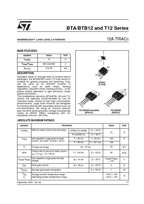
1/7®BTA/BTB12 and T12 SeriesSNUBBERLESS ™, LOGIC LEVEL & STANDARD12A TRIAC SSeptember 2002 - Ed: 6AMAIN FEATURES:DESCRIPTIONAvailable either in through-hole or surface-mount packages, the BTA/BTB12 and T12 triac series is suitable for general purpose AC switching. They can be used as an ON/OFF function in applications such as static relays, heating regulation, induction motor starting circuits... or for phase control operation in light dimmers, motor speed controllers,...The snubberless versions (BTA/BTB...W and T12series) are specially recommended for use on inductive loads, thanks to their high commutation performances. Logic level versions are designed to interface directly with low power drivers such as microcontrollers. By using an internal ceramic pad, the BTA series provides voltage insulated tab (rated at 2500V RMS) complying with UL standards (File ref.: E81734)Symbol Value Unit I T(RMS)12A V DRM /V RRM 600 and 800V I GT (Q 1)5 to 50mAABSOLUTE MAXIMUM RATINGSSymbol ParameterValueUnit I T(RMS)RMS on-state current (full sine wave)D ²PAK/TO-220AB Tc = 105°C 12A TO-220AB Ins.Tc = 90°C I TSM Non repetitive surge peak on-state current (full cycle, Tj initial = 25°C) F = 50 Hz t = 20 ms 120AF = 60 Hzt = 16.7 ms126I ²t I ²t Value for fusingtp = 10 ms78A ²s dI/dtCritical rate of rise of on-state current I G = 2 x I GT , tr ≤ 100 nsF = 120 Hz Tj = 125°C 50A/µs V DSM /V RSM Non repetitive surge peak off-statevoltagetp = 10 ms Tj = 25°C V DRM /V RRM+ 100V I GM Peak gate currenttp = 20 µsTj = 125°C 4A P G(AV)Average gate power dissipation Tj = 125°C1W T stg T jStorage junction temperature range Operating junction temperature range- 40 to + 150- 40 to + 125°CBTA/BTB12 and T12 Series2/7ELECTRICAL CHARACTERISTICS (Tj = 25°C, unless otherwise specified)sSNUBBERLESS™ and LOGIC LEVEL (3 Quadrants)sSTANDARD (4 Quadrants)STATIC CHARACTERISTICSNote 1: minimum IGT is guaranted at 5% of IGT max.Note 2: for both polarities of A2 referenced to A1Symbol Test ConditionsQuadrantT12BTA/BTB12UnitT1235TW SW CW BW I GT (1)V D = 12 V R L = 30 ΩI - II - III MAX.355103550mA V GT I - II - III MAX. 1.3V V GD V D = V DRM R L = 3.3 k ΩTj = 125°C I - II - IIIMIN.0.2V I H (2)I T = 100 mA MAX.3510153550mA I L I G = 1.2 I GTI - III MAX.5010255070mA II6015306080dV/dt (2)V D = 67 %V DRM gate open Tj = 125°CMIN.50020405001000V/µs (dI/dt)c (2)(dV/dt)c = 0.1 V/µs Tj = 125°CMIN.- 3.5 6.5--A/ms(dV/dt)c = 10 V/µs Tj = 125°C -1 2.9--Without snubber Tj = 125°C6.5-- 6.512Symbol Test ConditionsQuadrant BTA/BTB12UnitCB I GT (1)V D = 12 V R L = 30 ΩI - II - III IV MAX.255050100mA V GT ALL MAX. 1.3V V GD V D = V DRM R L = 3.3 k Ω Tj = 125°C ALLMIN.0.2V I H (2)I T = 500 mA MAX.2550mA I L I G = 1.2 I GTI - III - IVMAX.4050mA II80100dV/dt (2)V D = 67 %V DRM gate open Tj = 125°CMIN.200400V/µs (dV/dt)c (2)(dI/dt)c = 5.3 A/ms Tj = 125°CMIN.510V/µsSymbol Test ConditionsValue Unit V T (2)I TM = 17 A tp = 380 µs Tj = 25°C MAX. 1.55V V to (2)Threshold voltage Tj = 125°C MAX.0.85V R d (2)Dynamic resistance Tj = 125°C MAX.35m ΩI DRM I RRMV DRM = V RRMTj = 25°C MAX.5µA Tj = 125°C1mABTA/BTB12 and T12 Series3/7THERMAL RESISTANCESS = Copper surface under tabPRODUCT SELECTORBTB: non insulated TO-220AB packageORDERING INFORMATIONSymbol ParameterValue Unit R th(j-c)Junction to case (AC)D ²PAK/TO-220AB 1.4°C/W TO-220AB Insulated2.3R th(j-a)Junction to ambientS = 1 cm ²D ²PAK45°C/WTO-220ABTO-220AB Insulated60Part NumberVoltage (xxx)Sensitivity Type Package 600 V 800 V BTA/BTB12-xxxB X X 50 mA Standard TO-220AB BTA/BTB12-xxxBW X X 50 mA Snubberless TO-220AB BTA/BTB12-xxxC X X 25 mA Standard TO-220AB BTA/BTB12-xxxCW X X 35 mA Snubberless TO-220AB BTA/BTB12-xxxSW X X 10 mA Logic level TO-220AB BTA/BTB12-xxxTW X X 5 mA Logic Level TO-220AB T1235-xxxGXX35 mASnubberlessD ²PAKBTA/BTB12 and T12 Series4/7OTHER INFORMATIONNote: xxx = voltage, yy = sensitivity, z = typePart NumberMarkingWeight Base quantity Packing mode BTA/BTB12-xxxyz BTA/BTB12-xxxyz 2.3 g 250Bulk BTA/BTB12-xxxyzRG BTA/BTB12-xxxyz 2.3 g 50Tube T1235-xxxG T1235xxxG 1.5 g 50Tube T1235-xxxG-TRT1235xxxG1.5 g1000Tape & reelFig. 1: Maximum power dissipation versus RMSon-state current (full cycle).Fig. 2-1: RMS on-state current versus case temperature (full cycle).Fig. 2-2: RMS on-state current versus ambient temperature (printed circuit board FR4, copper thickness: 35µm),full cycle.Fig. 3: Relative variation of thermal impedance versus pulse duration.BTA/BTB12 and T12 Series5/7Fig. 4: On-state characteristics (maximum values).Fig. 5: Surge peak on-state current versus number of cycles.Fig. 6: Non-repetitive surge peak on-state current for a sinusoidal pulse with width tp <10ms, and corresponding value of I²t.Fig. 7: Relative variation of gate trigger current,holding current and latching current versus junction temperature (typical values).Fig. 8-1: Relative variation of critical rate of decrease of main current versus (dV/dt)c (typical values) (BW/CW/T1235).Fig. 8-2: Relative variation of critical rate of decrease of main current versus (dV/dt)c (typical values) (TW).BTA/BTB12 and T12 Series6/7Fig. 9: Relative variation of critical rate of decrease of main current versus junction temperature.Fig. 10: D²PAK Thermal resistance junction to ambient versus copper surface under tab (printed circuit board FR4, copper thickness: 35µm).PACKAGE MECHANICAL DATAFOOTPRINT DIMENSIONS (in millimeters)BTA/BTB12 and T12 Series PACKAGE MECHANICAL DATAInformation furnished is believed to be accurate and reliable. However, STMicroelectronics assumes no responsibility for the consequences of use of such information nor for any infringement of patents or other rights of third parties which may result from its use. No license is granted by implication or otherwise under any patent or patent rights of STMicroelectronics. Specifications mentioned in this publication are subject to change without notice. This publication supersedes and replaces all information previously supplied. STMicroelectronics products are not authorized for use as critical components in life support devices or systems without express written approval of STMicroelectronics.© The ST logo is a registered trademark of STMicroelectronics© 2002 STMicroelectronics - Printed in Italy - All Rights ReservedSTMicroelectronics GROUP OF COMPANIESAustralia - Brazil - Canada - China - Finland - France - GermanyHong Kong - India - Isreal - Italy - Japan - Malaysia - Malta - Morocco - SingaporeSpain - Sweden - Switzerland - United Kingdom - United States.7/7。
![[精彩]ta12_btb12系列产品规格书](https://img.taocdn.com/s1/m/8c341efb4bfe04a1b0717fd5360cba1aa8118cc1.png)
BTA12/BTB12系列产品规格书双向可控硅产品特点外形图及符号标志• NPNPN五层结构的硅双向器件;• 双面台面结构;• 台面玻璃钝化工艺;• 背面多层金属电极• 具有较高的阻断电压和较高的温度稳定性;• dv/dt高;• 适用于DB3触发和光耦触发;• TO-220AB、TO-220AB绝缘型、TO263型塑料封装;T1: 主端子1T2: 主端子2G : 触发极主要应用主要参数参数名称数值单位通态电流I T(RMS)12A • 吸尘器、电动工具等马达调速控制器;• 霓虹灯调光控制器;• 工业及家庭用加热控制(调温);•固态继电器;极限参数(绝对最大额定值)除非另有规定,这些极限值在整个工作范围内适用。
阻断电压V DRM /V RRM≥600V最大通态电压V TM≤1.55V 固态继电器;• 其它相控电路;序号参数名称符号数值单位最小值最大值1管壳温度Tcase -40125℃2储存温度Tstg -40150℃3有效结温T j -40125℃断态工作峰值电压V DWM 4804断作峰值压反向工作峰值电压V RWM 480V 5断态重复峰值电压反向重复峰值电压V DRM V RRM 600600V 6通态均方根电流360°导通角I T(RMS)12A 7通态浪涌电流F=50Hz t =20ms =167msI TSM120AF=60Hz t =16.7ms 1268I 2t值t P =10mSI 2t78A 2S9通态电流临界上升率(重复测试F=50Hz I G =50mA di g /d t =0.1A/uS)di/dt50A/uS10门极峰值电流Tp=20uS Tj=125℃I GM4A门极平均耗散功率11Tj=125℃P G(AV)1W产品电特性(除非另有规定,Tcase=25℃)序号特性和测试条件符号象限BTA12/BTB12单位最小值最大值CBC B 1通态峰值电压I T =17A V TM 1.55V 反向峰值电流(V RRM 下的漏电流)Tcase 25℃I 10uA 2Tcase=25℃Tcase=125℃RRM1I RRM21mA 3断态峰值电流(V DRM 下的漏电流)Tcase=25℃Tcase=125℃I DRM1I DRM2101uA mA 4维持电流I T=0.5A I H ALL2550mA 5擎住电流I G=1.2I GT I LⅠ、Ⅲ、Ⅳ4050mA Ⅱ801006控制极触发电流V D =12V I GT Ⅰ、Ⅱ、Ⅲ2550mA Ⅳ501007控制极触发电压V D =12V V GT ALL1.3V 8控制极不触发电压V D =600VT j =125℃V GD 0.2V 9断态电压临界上升率V D =400V门极开路T j =125℃dV/dt200400V/uS热阻名称符号数值单位热阻(结至壳温的最大值)R th(j-c)1.4/2.3℃/W型号说明BTA12可控硅产品A:绝缘型结构B:非绝缘型结构通态均方根电流为12A600B阻断电压≥600V触发电流分档序号:B:I GT1~I GT3 50mA Max C:I GT1~I GT3 25mA Max产品外形尺寸图TO-220AB封装外形图尺寸数据表(单位:mm):符号A B C D E F G H I J K L M N MIN15.2013.0010.00 2.6515.80 1.140.61 2.40 4.40 1.23 6.200.49 2.40 TYP 3.7516.40MAX15.9014.0014.00 2.9516.75 1.700.88 2.70 4.60 1.32 6.600.70 2.70 TO-263封装外形图尺寸数据表(单位:mm):符号A A1A2B B2C C2D E G L L2L3R MIN 4.30 2.490.030.70 1.250.45 1.218.9510.0 4.8815.0 1.27 1.40TYP 1.400.40 MAX 4.60 2.690.230.930.60 1.369.3510.28 5.2815.85 1.40 1.75常用电路图图1:电动工具软启动电路,软启动可以避免可控硅对电网的污染和电动工具启动时的抖动图2:双向可控硅用于自动咖啡机的控温电路,此电路使用过零触发光耦,可以联系信息望爵电子科技(上海)有限公司i ill l i h l i i d 图双向可控硅用于自动咖啡机的控温电路,此电路使用过零触发光耦,可以改善可控硅的触发特性。

可控硅資料/及工作原理和測試方法BTA06-400BW 6A 400V 50mA TO-220AB BTA06-400C 6A 400V 25mA TO-220ABBTA06-400CW 6A 400V 35mA TO-220AB BTA06-400TW 6A 400V 5mA TO-220AB BTA06-400E 6A 400V 5~10mA TO-220AB BTA06-400D 6A 400V 1~5mA TO-220AB BTA06-400SAP 6A 400V 5~10mA TO-220 BTA06-600B 6A 600V 35~50mA TO-220AB BTA06-600BW 6A 600V 50mA TO-220AB BTA06-600C 6A 600V 25mA TO-220ABBTA06-600CW 6A 600V 35mA TO-220A BTA06-600SW 6A 600V 10mA TO-220AB BTA06-600TW 6A 600V 5mA TO-220AB BTA06-600E 6A 600V 5~10mA TO-220AB BTA06-600D 6A 600V 1~5mA TO-220AB BTA06-600SAP 6A 600V 5~10mA TO-220AB BTA06-700B 6A 700V 35~50mA TO-220AB BTA06-700BW 6A 700V 50mA TO-220ABBTA06-700C 6A 700V 25mA TO-220AB BTA06-700CW 6A 700V 35mA TO-220AB BTA06-700SW 6A 700V 10mA TO-220AB BTA06-700TW 6A 700V 5mA TO-220AB BTA06-700E 6A 700V 5~10mA TO-220AB BTA06-700D 6A 700V 1~5mA TO-220AB BTA06-700SAP 6A 700V 5~10mA TO-220AB BTA06-800B 6A 800V 35~50mA TO-220AB BTA06-800BW 6A 800V 50mA TO-220AB BTA06-800C 6A 800V 25mA TO-220AB BTA06-800CW 6A 800V 35mA TO-220AB BTA06-800SW 6A 800V 10mA TO-220AB BTA06-800TW 6A 800V 5mA TO-220AB BTA06-800E 6A 800V 5~10mA TO-220AB BTA06-800D 6A 800V 1~5mA TO-220AB BTA06-800SAP 6A 800V 5~10mA TO-220AB BTB06-400B 6A 400V 35~50mA TO-220A BTB06-400BW 6A 400V 50mA TO-220AB BTB06-400C 6A 400V 25mA TO-220ABBTB06-400SW 6A 400V 10mA TO-220AB BTB06-400TW 6A 400V 5mA TO-220AB BTB06-400E 6A 400V 5~10mA TO-220AB BTB06-400D 6A 400V 1~5mA TO-220AB BTB06-400SAP 6A 400V 5~10mA TO-220AB BTB06-600B 6A 600V 35~50mA TO-220A BTB06-600BW 6A 600V 50mA TO-220AB BTB06-600C 6A 600V 25mA TO-220AB BTB06-600CW 6A 600V 35mA TO-220AB BTB06-600SW 6A 600V 10mA TO-220AB BTB06-600TW 6A 600V 5mA TO-220AB BTB06-600E 6A 600V 5~10mA TO-220BTB06-600D 6A 600V 1~5mA TO-220AB BTB06-600SAP 6A 600V 5~10mA TO-220AB BTB06-700B 6A 700V 35~50mA TO-220AB BTB06-700BW 6A 700V 50mA TO-220AB BTB06-700C 6A 700V 25mA TO-220AB BTB06-700CW 6A 700V 35mA TO-220ABBTB06-700TW 6A 700V 5mA TO-220AB BTB06-700E 6A 700V 5~10mA TO-220AB BTB06-700D 6A 700V 1~5mA TO-220AB BTB06-700SAP 6A 700V 5~10mA TO-220AB BTB06-800B 6A 800V 35~50mA TO-220AB BTB06-800BW 6A 800V 50mA TO-220AB BTB06-800C 6A 800V 25mA TO-220AB BTB06-800CW 6A 800V 35mA TO-220AB BTB06-800SW 6A 800V 10mA TO-220AB BTB06-800TW 6A 800V 5mA TO-220AB BTB06-800E 6A 800V 5~10mA TO-220AB BTB06-800D 6A 800V 1~5mA TO-220AB BTB06-800SAP 6A 800V 5~10mA TO-220ABBTA08-400B 8A 400V 35~50mA TO-220AB BTA08-400BW 8A 400V 50mA TO-220AB BTA08-400C 8A 400V 25mA TO-220AB BTA08-400CW 8A 400V 35mA TO-220ABBTA08-400TW 8A 400V 5mA TO-220AB BTA08-400E 8A 400V 5~10mA TO-220AB BTA08-400D 8A 400V 1~5mA TO-220AB BTA08-400SAP 8A 400V 5~10mA TO-220AB BTA08-600B 8A 600V 35~50mA TO-220AB BTA08-600BW 8A 600V 50mA TO-220AB BTA08-600C 8A 600V 25mA TO-220AB BTA08-600CW 8A 600V 35mA TO-220AB BTA08-600SW 8A 600V 10mA TO-220AB BTA08-600TW 8A 600V 5mA TO-220AB BTA08-600E 8A 600V 5~10mA TO-220AB BTA08-600D 8A 600V 1~5mA TO-220AB BTA08-600SAP 8A 600V 5~10mA TO-220AB BTA08-700B 8A 700V 35~50mA TO-220AB BTA08-700BW 8A 700V 50mA TO-220AB BTA08-700C 8A 700V 25mA TO-220AB BTA08-700CW 8A 700V 35mA TO-220AB BTA08-700SW 8A 700V 10mA TO-220ABBTA08-700E 8A 700V 5~10mA TO-220AB BTA08-700D 8A 700V 1~5mA TO-220AB BTA08-700SAP 8A 700V 5~10mA TO-220AB BTA08-800B 8A 800V 35~50mA TO-220AB BTA08-800BW 8A 800V 50mA TO-220AB BTA08-800C 8A 800V 25mA TO-220ABBTA08-800CW 8A 800V 35mA TO-220AB BTA08-800SW 8A 800V 10mA TO-220AB BTA08-800TW 8A 800V 5mA TO-220AB BTA08-800E 8A 800V 5~10mA TO-220AB BTA08-800D 8A 800V 1~5mA TO-220AB BTA08-800SAP 8A 800V 5~10mA TO-220A BTA08-1000B 8A 1000V 35~50mA TO-220AB BTA08-1000BW 8A 1000V 50mA TO-220AB BTA08-1000C 8A 1000V 25mA TO-220AB BTA08-1000CW 8A 1000V 35mA TO-220AB BTA08-1000SW 8A 1000V 10mA TO-220AB BTA08-1000TW 8A 1000V 5mA TO-220ABBTA08-1000E 8A 1000V 5~10mA TO-220AB BTA08-1000D 8A 1000V 1~5mA TO-220AB BTA08-1000SAP 8A 1000V 5~10mA TO-220AB BTB08-400B 8A 400V 35~50mA TO-220AB BTB08-400BW 8A 400V 50mA TO-220AB BTB08-400C 8A 400V 25mA TO-220ABBTB08-400CW 8A 400V 35mA TO-220AB BTB08-400SW 8A 400V 10mA TO-220ABBTB08-400TW 8A 400V 5mA TO-220ABBTB08-400E 8A 400V 5~10mA TO-220ABTB08-400D 8A 400V 1~5mA TO-220ABBTB08-400SAP 8A 400V 5~10mA TO-220AB BTB08-600B 8A 600V 35~50mA TO-220A BTB08-600BW 8A 600V 50mA TO-220AB BTB08-600C 8A 600V 25mA TO-220ABBTB08-600CW 8A 600V 35mA TO-220AB BTB08-600SW 8A 600V 10mA TO-220ABBTB08-600TW 8A 600V 5mA TO-220ABBTB08-600E 8A 600V 5~10mA TO-220ABBTB08-600D 8A 600V 1~5mA TO-220AB BTB08-600SAP 8A 600V 5~10mA TO-220AB BTA10-400B 10A 400V 35~50mA TO-220AB BTA12-400B 12A 400V 35~50mA TO-220AB BTA16-400B 16A 400V 35~50mA TO-220AB BTA20-400B 20A 400V 35~50mA TO-220AB BTA24-600B 25A 600V 35~50mA TO-220ABBTA25-600B 25A 600V 35~50mA TO-220AB BTA25-600BW 25A 600V 50mA TO-220AB BTA26-600B 25A 600V 35~50mA TO-220AB BTA40-600B 40A 600V 35~50mA BTW67 BTA40-600BW 40A 600V 50mA BTW67 BTA41-600B 40A 600V 35~50mA BTW67 BTA41-600BW 40A 600V 50mA BTW67 HBT131A 1A 600V 3~7mA TO-92HBT131CA 1A 600V 3~5mA TO-92HBT131GA 1A 800V 3~5mA TO-92HBT134CI 4A 600V 5~10mA TO-251HBT134DI 4A 600V 5~10mA TO-251 HBT134GI 4A 800V 5~10mA TO-251 HBT134HI 4A 600V 5~10mA TO-251 HBT134NE 4A 600V 10~25mA SOT-82 HBT134I 4A 600V 10~25mA TO-251HBT134CNE 4A 600V 5~10mA SOT-82 HBT134DNE 4A 600V 5~10mA SOT-82 HBT134GNE 4A 800V 5~10mA SOT-82 HBT134HNE 4A 800V 5~10mA SOT-82 HBT136AE 4A 600V 10mA TO-220AB HBT204I 4A 600V 10mA TO-251HBT204E 4A 600V 15mA TO-220ABHBT136AE 4A 600V 10~25mA TO-220AB HBT136AHE 4A 600V 5~10mA TO-220AB HBT136BE 6A 600V 10~25mA TO-220AB HBT137E 8A 600V 10~25mA TO-220AB HBT137DE 8A 600V 25mA TO-220AB HBT138E 8A 600V 10~25mA TO-220AB HBT152 20A 800V 32mA TO-220ABHBT169 0.8A 400V 200uA TO-92HBT169M 0.8A 400V 200uA SOT-8可控硅相当于可以控制的二极管,当控制极加一定的电压时,阴极和阳极就导通了。

IAC-SEP®维生素B12免疫亲和柱(产品编号:IAC315)使用对象IAC-SEP®维生素B12亲和柱能够特异性的纯化样品中的维生素B12,它采用了柱状琼脂糖凝胶作为固相载体,琼脂糖凝胶与维生素B12抗体偶联形成免疫吸附剂,装柱制成免疫亲和柱。
它能够特异性的纯化样品中的维生素B12。
维生素B12亲和柱广泛地应用于饮料、牛奶和奶粉,饮料等样品的提取,该方法速度快、操作简单、准确性高,对提高食品的质量和安全性起到十分重要的作用。
维生素B12家族中有四大成员:氰钴胺、甲钴胺、腺苷钴胺和羟钴胺. 自然界中,微生物生物合成的维生素B12最终形式为甲钴胺、腺苷钴胺和羟钴胺;但是由于它们性质不太稳定,所以在工业提纯过程中人为地加入氰化钠,使天然形式的维生素B12转化为性质更为稳定的氰钴胺。
我们俗称的维生素B12,是指氰钴胺,我们食品中添加的维生素B12为氰钴胺,因此我们检测食品中的维生素B12只需检测氰钴胺。
该说明书方法应用亲和柱方法检测食品中维生素B12(氰钴胺)的检测方法。
如需检测氰钴胺、甲钴胺、腺苷钴胺和羟钴胺总量的方法,请参考以下两种方法进行样品的前处理,然后再应用本亲和柱进行净化:AOAC2014.02:Improved_AOAC-FirstAction 2011.08 for the Analysis of Vitamin B12 in Infant Formula and Adult Pediatric Formulas First Action 2014.02(2)GB 食品安全国家标准:GB 5009.285-2022 食品安全国家标准食品中维生素B12的测定GB/T 5009.217-2008 保健食品中维生素B12的测定T/NAIA 048-2021 功能性饮料中维生素B12的测定液相色谱-质谱/质谱法原理维生素B12免疫亲和柱能够特异性的纯化样品中的维生素B12,将样品与提取液混合、提取、过滤,然后将滤液通过免疫亲和柱。
双向可控硅为什么称为“TRIAC”?三端:TRIode(取前三个字母)交流半导体开关:AC-semiconductor switch(取前两个字母)以上两组名词组合成“TRIAC”,或“TRIACs”中文译意“三端双向可控硅开关”。
由此可见“TRIAC”是双向可控硅的统称。
另:双向:Bi-directional(取第一个字母)控制:Controlled (取第一个字母)整流器:Rectifier (取第一个字母)再由这三组英文名词的首个字母组合而成:“BCR”,中文译意:双向可控硅。
以“BCR”来命名双向可控硅的典型厂家如日本三菱,如:BCR1AM-12、BCR8KM、BCR08AM 等等。
--------------双向:Bi-directional (取第一个字母)三端:Triode (取第一个字母)由以上两组单词组合成“BT”,也是对双向可控硅产品的型号命名,典型的生产商如:意法ST公司、荷兰飞利浦-Philips公司,均以此来命名双向可控硅.代表型号如:PHILIPS 的BT131-600D、BT134-600E、BT136-600E、BT138-600E、BT139-600E、、等。
这些都是四象限/非绝缘型/双向可控硅;Philips公司的产品型号前缀为“BTA”字头的,通常是指三象限的双向可控硅。
三象限的品种主要应用于电机电路、三相市电输入的电路、承受的瞬间浪涌电流高。
-------------------而意法ST公司,则以“BT”字母为前缀来命名元件的型号,并且在“BT”后加“A”或“B”来表示绝缘与非绝缘。
组成:“BTA”、“BTB”系列的双向可控硅型号,如:四象限、绝缘型、双向可控硅:BTA06-600C、BTA08-600C、BTA10-600B、BTA12-600B、BTA16-600B、BTA41-600、、、等等;四象限、非绝缘、双向可控硅:BTB06-600C、BTB08-600C、BTB10-600B、BTB12-600B、BTB16-600B、BTB41-600、、、等等;ST公司所有产品型号的后缀字母(型号最后一个字母)带“W”的,均为“三象限双向可控硅”。
1/7®BTA/BTB12 and T12 SeriesSNUBBERLESS ™, LOGIC LEVEL & STANDARD12A TRIAC SSeptember 2000 - Ed: 3MAIN FEATURES:DESCRIPTIONAvailable either in through-hole or surface-mount packages, the BTA/BTB12 and T12 triac series is suitable for general purpose AC switching. They can be used as an ON/OFF function in applications such as static relays, heating regulation, induction motor starting circuits... or for phase control operation in light dimmers, motor speed controllers,...The snubberless versions (BTA/BTB...W and T12series) are specially recommended for use on inductive loads, thanks to their high commutation performances. By using an internal ceramic pad,the BTA series provides voltage insulated tab (rated at 2500V RMS) complying with UL standards (File ref.: E81734)Symbol Value Unit I T(RMS)12A V DRM /V RRM 600 and 800V I GT (Q 1)10 to 50mAABSOLUTE MAXIMUM RATINGSSymbol ParameterValueUnit I T(RMS)RMS on-state current (full sine wave)D ²PAK/TO-220AB Tc = 105°C 12A TO-220AB Ins.Tc = 90°C I TSM Non repetitive surge peak on-state current (full cycle, Tj initial = 25°C) F = 50 Hz t = 20 ms 120AF = 60 Hzt = 16.7 ms126I ²t I ²t Value for fusingtp = 10 ms100A ²s dI/dtCritical rate of rise of on-state current I G = 2 x I GT , tr ≤ 100 nsF = 120 Hz Tj = 125°C 50A/µs V DSM /V RSM Non repetitive surge peak off-statevoltagetp = 10 ms Tj = 25°C V DRM /V RRM+ 100V I GM Peak gate currenttp = 20 µsTj = 125°C 4A P G(AV)Average gate power dissipation Tj = 125°C1W T stg T jStorage junction temperature range Operating junction temperature range- 40 to + 150- 40 to + 125°CBTA/BTB12 and T12 Series2/7ELECTRICAL CHARACTERISTICS (Tj = 25°C, unless otherwise specified)sSNUBBERLESS™ and LOGIC LEVEL (3 Quadrants)sSTANDARD (4 Quadrants)STATIC CHARACTERISTICSNote 1: minimum IGT is guaranted at 5% of IGT max.Note 2: for both polarities of A2 referenced to A1Symbol Test ConditionsQuadrantT12BTA/BTB12UnitT1235SW CW BW I GT (1)V D = 12 V R L = 30 ΩI - II - III MAX.35103550mA V GT I - II - III MAX. 1.3V V GD V D = V DRM R L = 3.3 k ΩTj = 125°C I - II - IIIMIN.0.2V I H (2)I T = 100 mA MAX.35153550mA I L I G = 1.2 I GTI - III MAX.50255070mA II60306080dV/dt (2)V D = 67 %V DRM gate open Tj = 125°CMIN.500405001000V/µs (dI/dt)c (2)(dV/dt)c = 0.1 V/µs Tj = 125°C MIN.- 6.5--A/ms(dV/dt)c = 10 V/µs Tj = 125°C - 2.9--Without snubber Tj = 125°C6.5- 6.512Symbol Test ConditionsQuadrant BTA/BTB06UnitCB I GT (1)V D = 12 V R L = 30 ΩI - II - III IV MAX.255050100mA V GT ALL MAX. 1.3V V GD V D = V DRM R L = 3.3 k Ω Tj = 125°C ALLMIN.0.2V I H (2)I T = 500 mA MAX.2550mA I L I G = 1.2 I GTI - III - IVMAX.4050mA II80100dV/dt (2)V D = 67 %V DRM gate open Tj = 125°CMIN.200400V/µs (dV/dt)c (2)(dI/dt)c = 5.3 A/ms Tj = 125°CMIN.510V/µsSymbol Test ConditionsValue Unit V T (2)I TM = 17 A tp = 380 µs Tj = 25°C MAX. 1.55V V to (2)Threshold voltage Tj = 125°C MAX.0.85V R d (2)Dynamic resistance Tj = 125°C MAX.35m ΩI DRM I RRMV DRM = V RRMTj = 25°C MAX.5µA Tj = 125°C1mABTA/BTB12 and T12 Series3/7THERMAL RESISTANCESS = Copper surface under tabPRODUCT SELECTORBTB: non insulated TO-220AB packageORDERING INFORMATIONSymbol ParameterValue Unit R th(j-c)Junction to case (AC)D ²PAK/TO-220AB 1.4°C/W TO-220AB Insulated2.3R th(j-a)Junction to ambientS = 1 cm ²D ²PAK45°C/WTO-220ABTO-220AB Insulated60Part NumberVoltage (xxx)Sensitivity Type Package 600 V 800 V BTA/BTB12-xxxB X X 50 mA Standard TO-220ABBTA/BTB12-xxxBW X X 50 mA Snubberless TO-220AB BTA/BTB12-xxxC X X 25 mA Standard TO-220AB BTA/BTB12-xxxCW X X 35 mA Snubberless TO-220AB BTA/BTB12-xxxSW X X 10 mA Logic level TO-220AB T1235-xxxGXX35 mASnubberlessD ²PAKBTA/BTB12 and T12 Series4/7OTHER INFORMATIONNote: xxx = voltage, yy = sensitivity, z = typePart NumberMarkingWeight Base quantity Packing mode BTA/BTB12-xxxyz BTA/BTB12-xxxyz 2.3 g 250Bulk T1235-xxxG T1235xxxG 1.5 g 50Tube T1235-xxxG-TRT1235xxxG1.5 g1000Tape & reelFig. 1: Maximum power dissipation versus RMS on-state current (full cycle).Fig. 2-1: RMS on-state current versus case temperature (full cycle).Fig. 2-2: RMS on-state current versus ambient temperature (printed circuit board FR4, copperthickness: 35µm),full cycle.Fig. 3: Relative variation of thermal impedance versus pulse duration.BTA/BTB12 and T12 Series5/7Fig. 4: On-state characteristics (maximum values).Fig. 5: Surge peak on-state current versus number of cycles.Fig. 6: Non-repetitive surge peak on-state current for a sinusoidal pulse with width tp <10ms, and corresponding value of I²t.Fig. 7: Relative variation of gate trigger current,holding current and latching current versus junction temperature (typical values).Fig. 8: Relative variation of critical rate of decrease of main current versus (dV/dt)c (typical values).Fig. 9: Relative variation of critical rate of decrease of main current versus junction temperature.BTA/BTB12 and T12 SeriesFig. 10: D²PAK Thermal resistance junction to ambient versus copper surface under tab (printed circuit board FR4, copper thickness: 35µm).PACKAGE MECHANICAL DATAFOOTPRINT DIMENSIONS (in millimeters)6/7BTA/BTB12 and T12 Series PACKAGE MECHANICAL DATAInformation furnished is believed to be accurate and reliable. However, STMicroelectronics assumes no responsibility for the consequences of use of such information nor for any infringement of patents or other rights of third parties which may result from its use. No license is granted by implication or otherwise under any patent or patent rights of STMicroelectronics. Specifications mentioned in this publication are subject to change without notice. This publication supersedes and replaces all information previously supplied. STMicroelectronics products are not authorized for use as critical components in life support devices or systems without express written approval of STMicroelectronics.© The ST logo is a registered trademark of STMicroelectronics© 2000 STMicroelectronics - Printed in Italy - All Rights ReservedSTMicroelectronics GROUP OF COMPANIESAustralia - Brazil - China - Finland - France - Germany - Hong Kong - India - Italy - Japan - Malaysia - Malta - MoroccoSingapore - Spain - Sweden - Switzerland - United Kingdom7/7。