主流微波雷达人体红外感应LD602芯片规格书
- 格式:pdf
- 大小:362.60 KB
- 文档页数:8
SR602人体感应模块代码1. 介绍SR602人体感应模块是一种基于红外技术的传感器模块,用于检测周围环境中的人体活动。
它可以广泛应用于安防系统、智能家居、自动化控制等领域。
本文将介绍如何使用SR602人体感应模块,并给出相应的代码示例。
2. 模块特点•灵敏度高:SR602人体感应模块采用高质量的红外传感器,能够准确感知人体的活动。
•可调节参数:模块内置了灵敏度调节电位器,可以根据实际需求进行灵敏度的调整。
•低功耗:SR602人体感应模块采用低功耗设计,工作电流仅为2.8mA。
•高可靠性:模块具有温度补偿和电源电压监测功能,能够提高系统的可靠性和稳定性。
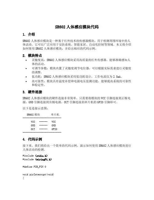
3. 硬件连接SR602人体感应模块的硬件连接非常简单,只需要将模块的VCC引脚连接到正极电源,GND引脚连接到负极电源,OUT引脚连接到单片机的GPIO引脚即可。
以下是连接示意图:SR602模块单片机----------------------------VCC ------ VCCGND ------ GNDOUT ------ GPIO----------------------------4. 代码示例接下来,我们将给出一个简单的代码示例,演示如何使用SR602人体感应模块进行人体活动的检测。
#include <stdio.h>#include <wiringPi.h>#define PIR_PIN 0void pirInterrupt(void){printf("Motion detected!\n");}int main(void){wiringPiSetup();pinMode(PIR_PIN, INPUT);wiringPiISR(PIR_PIN, INT_EDGE_RISING, pirInterrupt);while (1){delay(1000);}return 0;}在这段代码中,我们使用wiringPi库来控制GPIO引脚。

sr602人体感应模块代码【原创版】目录1.介绍 SR602 人体感应模块2.SR602 人体感应模块的工作原理3.SR602 人体感应模块的代码编写4.SR602 人体感应模块的应用领域正文一、介绍 SR602 人体感应模块SR602 人体感应模块是一种红外热释传感器,它能够检测到人体发射的红外辐射。
该模块具有灵敏度高、反应速度快、抗干扰能力强等优点,广泛应用于智能家居、安防监控、医疗保健等领域。
二、SR602 人体感应模块的工作原理SR602 人体感应模块基于热释电效应原理工作。
当人体进入模块的检测范围时,人体会发射红外辐射,这些辐射被模块接收并转换为电信号。
电信号的大小与红外辐射的强度成正比,因此当人体进入检测范围时,模块输出的电压会相应地发生变化。
三、SR602 人体感应模块的代码编写以下是一个基于 Arduino 的 SR602 人体感应模块代码示例:```c// 定义模块连接的引脚const int sensorPin = A0;void setup() {// 设置传感器引脚为输入pinMode(sensorPin, INPUT);}void loop() {// 读取传感器引脚的值int sensorValue = analogRead(sensorPin);// 判断传感器值是否超过阈值if (sensorValue > 600) {// 当人体进入检测范围时,执行相应操作Serial.println("人体进入检测范围");} else {// 当人体离开检测范围时,执行相应操作Serial.println("人体离开检测范围");}// 等待 100 毫秒,进行下一次循环delay(100);}```四、SR602 人体感应模块的应用领域SR602 人体感应模块广泛应用于各种场景,例如:1.智能家居:用于自动控制照明、空调等设备,实现节能和人性化家居环境。

AD602:双通道、低噪声、宽带可变增益放⼤器(增益范围-10 dB⾄+30 dB)AD600/AD602均为双通道、低噪声、可变增益放⼤器,并针对超声成像系统应⽤进⾏了优化,但同样适⽤于任何要求精确增益、低噪声、低失真和宽带宽的应⽤。
每个独⽴通道均提供0 dB⾄+40 dB(AD600)/-10 dB⾄+30 dB(AD602)增益。
AD602的增益较低,可改善输出的信噪⽐(SNR)。
不过,两款产品均具有相同的1.4 nV/√Hz输⼊噪声谱密度。
dB增益与控制电压成正⽐关系,经过精密校准,⽽且不随电源电压和温度⽽变化。
为实现⾼难度的性能⽬标,ADI公司开发出⼀种专有电路形式X-AMP®。
X-AMP的每个通道均含有0 dB⾄-42.14 dB可变衰减器,后接⾼速固定增益放⼤器。
这样,放⼤器永远不必处理较⼤输⼊,并且还可以利⽤负反馈来精确定义增益和动态范围。
衰减器以7级R-2R梯形⽹络的形式实现,具有经激光调整⾄±2%的100Ω输⼊电阻。
触点之间的衰减为6.02 dB,增益控制电路提供这些触点之间的连续插值,由此便可获得以dB为单位的线性控制功能。
增益控制接⼝为完全差分接⼝,提供约15 MΩ的输⼊电阻以及由内部基准电压定义的32 dB/V(即31.25 mV/dB)⽐例因⼦。
此接⼝的响应时间不到1 µs。
每个通道还具有独⽴的选通设置,可以选择性阻⽌信号传输,并将直流输出电平设置在输出地电压的数毫伏范围以内。
选通控制输⼊为TTL/CMOS兼容。
AD600的最⼤增益为41.07 dB,AD602的最⼤增益为31.07 dB;两种型号的-3 dB带宽标称值均为35 MHz,基本上与增益⽆关。
1 V均⽅根输出和1 MHz噪声带宽的SNR典型值为76 dB(AD600)/86 dB(AD602)。
在100 kHz⾄10 MHz范围内,振幅响应平坦度为±0.5 dB;超出此频率范围时,所有增益设置的群延迟变化幅度均⼩于±2 ns。
红外微波人体探测器(含光强温湿度探测)产品使用说明书适用于WH-ZSPCNPW-PI23WM2THAL-01©2015 南京物联传感技术有限公司出版号:2015-0427.V01欢迎您使用物联之家多功能抗干扰人体探测器产品说明书●物联之家是南京物联传感技术有限公司的注册商标,本说明书中提到的所有其他产品名称或商标是其各自品牌所有者的商标或注册商标。
●使用前请您一定认真阅读产品使用说明书,确保正确、安全地使用。
●物联之家多功能抗干扰人体探测器(以下简称“本产品”)为南京物联传感技术有限公司(以下简称“我司”)出品的智能家居安防类产品。
本产品需要与智能家居相应APP客户端同步使用,并须使用本产品自带的配件,如果您未正确地安装及使用本产品而造成的损失,我司将不承担任何责任。
●我司随时可能对本说明书中的产品信息进行更新,恕不另行通知。
请您及时关注我司资讯,下载最新版的APP客户端。
●未经我司的明确书面许可,任何个人及企业不得复制本说明书的全部或部分内容,不得使用我司注册商标。
对非法使用我司商标的行为,我司将依法追究行为人及企业法律责任。
●欢迎您登录我司官网,了解更多智能家居产品信息。
产品特点●采用红外与微波同步探测技术,不仅抗环境干扰能力强,而且探测时信号稳定、精确;●能够同时检测室内的光线强度与环境温湿度,根据搜集到的信息,可智能切换家居的多种自定义场景模式;●本产品可与我司旗下任意安防类设备联动设防,保护您的财产安全;●具有防拆功能,当检测设备被拆下时,智能家居相应的APP客户端将立即接收到提示信息;●本产品的PIR红外探测器件采用双元补偿结构,对人体探测具有较高的灵敏度;●本产品集成了温湿度传感器和信号处理电路,具有数据准确、响应迅速等优点;●本产品的光敏传感器件能够精确探测到1~65535 lx的光通量;●核心系统功耗低,属于新一代绿色产品。
产品装箱清单说明书保修卡多功能抗干扰人体探测器主体*1 吸顶式底座*1 壁挂式底座*1膨胀管+自攻螺丝*2 说明书*1 保修卡*1探测区域安装辅助卡安装辅助卡*1产品安装示意图注:使用时务必采用吸顶安装,电源线建议剥线10mm。

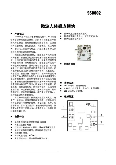
新型红外雷达感应模块(电源)产品概述:新型红外雷达感应模块(电源)是利用PIR 热释电与多普勒效应相结合原理设计而成的人体移动信号侦测器,它以非接触方式扫描人体PIR热释电信号的位置是否发生移动,继而产生相应的开关操作。
该产品具有抗射频干扰能力强、不怕风吹草动、树叶摇曳、电风扇转动、空调冷热气体流动、浴室浴霸温度骤变......不受温度、湿度、强光、噪音、气流、尘埃等外界因数影响,能透过一定厚度的塑胶、玻璃、木制品等金属以外的物体,而对其侦测能力没有影响,能够非常方便的应用到设备控制、环境辅助光源控制、地下停车场、仓库、通道、走廊、洗手间等室内外的照明及防盗报警、视频监控、自动化设备控制等各种领域。
功能特点:新型红外雷达感应模块(电源)采用发射、接收为一体的平面天线和PIR热释电红外解码系统BISS0001形成的红外雷达移动波侦测新技术,通过多普勒扫描,侦测人体、车辆的动态信号,对灯具、报警装置等进行有效控制。
产品独创抗干扰新技术,相互不干扰,安装不必考虑间接距离问题!可以安装在天花板或灯具内部,而侦测能力不会受到影响,更简洁、更美观、更隐蔽、更神秘、更安全!模块类型1、交流型:A C95-250V宽电压,适应各种不同地区电网电压。
可控硅控制A C输出,无触点、无噪音、无污染、寿命长。
具有自动测光管理功能(出厂未安装光敏电阻),实现白天(光线充足)呈关闭状态,晚上(光线不足)人来灯亮、人走灯灭。
可做吸顶灯、日光灯及各种灯具、电器等的自动控制。
交流模块技术参数❖工作电压:A C110V-250V(50-60H z)❖负载功率:阻性负载150W(节能灯、L E D灯80W)❖输出方式:可控硅控制、A C交流输出❖自身功耗:静态功耗≤1m W❖感应范围:10-15米❖感应角度:墙壁安装180°、吸顶安装360°❖触发方式:雷达扫描、人体感应、重复触发❖延时时间:30秒钟(可定做各种延时时间)❖模块尺寸:36m m*23m m*23m m❖环境温度:-30℃-70℃2、直流型:D C6-24V输入,有人在感应区活动时,输出高电平,无人活动时转换为低电平。

OS100 SERIES Mini-Infrared Transmitter e-mail:**************For latest product manuals: Shop online at User’s G ui d e***********************Servicing North America:U.S.A. Omega Engineering, Inc.Headquarters: Toll-Free: 1-800-826-6342 (USA & Canada only)Customer Service: 1-800-622-2378 (USA & Canada only)Engineering Service: 1-800-872-9436 (USA & Canada only)Tel: (203) 359-1660 Fax: (203) 359-7700e-mail:**************For Other Locations Visit /worldwideThe information contained in this document is believed to be correct, but OMEGA accepts no liability for any errors it contains, and reserves the right to alter specifications without notice.Table of ContentsSection ...................................................................PageSafety Warnings and IEC Symbols (iii)Caution and Safety Information (iii)Section 1 Introduction ....................................................................1-1Section 2Installation ......................................................................1-12.1 Unpacking and Inspection ......................................1-12.2 Electrical Connection ..............................................2-1Section 3Operation ........................................................................3-13.1 Main Board ................................................................3-13.2 Ambient Temperature ..............................................3-23.3 Atmospheric Quality ................................................3-33.4 Measuring Temperature ..........................................3-33.5 Alarm Setting ............................................................3-43.6 Adding Extension Cable...........................................3-4Section 4 Laser Sight Accessory ...................................................4-14.1 Warning and Cautions .............................................4-14.2 Operating the Laser Sight Accessory .....................4-1Section 5 Specifications .................................................................5-15.1 General .......................................................................5-15.2 Laser Sight Accessory (OS100-LS) ..........................5-2Section 6Emissivity Table .............................................................6-1iTable of FiguresFigure Description Page2-1Power Supply & Analog Output Connections ..........2-12-2 Alarm Output Connection ............................................2-13-1 Main PC Board ...............................................................3-23-2 Sensor..............................................................3-2Housing3-3 Optical Field of View .....................................................3-43-4Setting the Temperature Engineering Unit..................3-43-5Mounting Bracket OS100-MB .......................................3-53-6Water Cooling Jacket, OS100-WC ................................3-53-7Typical Water Cool Jacket Assembly ...........................3-53-8Air Purge Collar, OS100-AP..........................................3-63-9DIN Rail Mounting Adapter, OS100-DR ....................3-63-10NEMA-4 Aluminum Enclosure ....................................3-64-1Laser Sighting Accessory, OS100-LS ............................4-24-2Laser Warning Label ......................................................4-2iiSafety Warnings and IEC SymbolsThis device is marked with international safety and hazard symbols in accordance with IEC 1010. It is important to read and follow all precautions and instructions in this manual before operating or commissioning this device as it contains important information relating to safety and EMC. Failure to follow all safety precautions may result in injury and or damage to your calibrator. IEC symbols DescriptionCaution and Safety Information• If the equipment is used in a manner not specified in this manual, the protection provided by the equipment may be impaired.• The installation category is one (1).• There are no user replaceable fuses in this product• The output terminals of this product are for use with equipment (digital meters, chart recorders, etc,) which have no accessible five parts. Such equipment should comply with all the applicable safety requirements.• Do not operate the equipment in flammable or explosive environments.• All connections to the thermometer should be made via a shielded cable, 24 AWG stranded wire with the following ratings: 300V , 105°C (221°F), PVC insulation.• Power must be disconnected before making any electrical connections.• The power supply used to power the thermometer should be VDE or UL approved with the following ratings: 12 to 24vdc @150mA with overload protection of 500mA.iiiCaution, refer to accompanying documentsDirect Current Laser SymbolFrame or ChassisNOTES: ivSection 1 - IntroductionThe low cost OS101 mini-infrared transmitter provides non-contacttemperature measurement for industrial applications. The unit measures atemperature range of -18 to 538°C (0-1000°F) and provides a linear analogoutput of either 4-20 mA, 0-5 VDC, K type TC, 1 mV/°C, or 1 mV/°F.The new OS102 mini-infrared transmitter has all the functions of OS101plus a built-in LED display that shows the measured temperature indegrees F or degrees C which is switchable in the field.The miniature sensor head design 2.5 cm dia. x 6.3 cm Length (1" x 2.5") isideal for measuring temperature in confined, and hard to reach places.The aluminum sensor head as well as the rugged electronic housing (Diecast Aluminum) are NEMA-4 rated.The sensor head is connected to the electronic housing via a 1.82 m (6 feet)shielded cable as standard. The unit provides field adjustable alarmoutput.Section 2 - Installation2.1UnpackingRemove the packing list and verify that you have received all yourequipment. If you have any questions about the shipment, please callCustomer Service at:1-800-622-2378 or 203-359-1660. We can also be reached on the internet:e-mail:**************When you receive the shipment, inspect the container and equipment forany signs of damage. Note any evidence of rough handling in transit.inspection. After examination and removing contents, save packing material and carton in theevent reshipment is necessary.The following items are supplied in the box:• The infrared transmitter including the sensor head and the 1.82 m(6 feet) shielded cable• User's Manual• Mounting Nut1-1The following describes the ordering information:OS102 or OS101 - MA- *,**, where The following optional accessories are available:Here are the Features of OS101 and OS102 infrared transmitters:2.2Electrical Connection Sensor Head Cable - The Sensor head is pre-wired to a 1.8 m (6 feet)shielded cable. Plug & lock-in the male connector to the mating female connector on the aluminum housing.Power & Output Connection - Open the cover of the main aluminum housing. Slide the cable through the strain relief and connect the wires to the terminal block on the board as shown in Fig. 2-1. For Alarm output connection, refer to Fig. 2-2.2-1MA - 4/20 mA output V1 - 0 to 5 VDC output K - Thermocouple output, K type MV - Millivolt output C - 1 mV/°C output F - 1 mV/°F output HT- High temperature sensor head3-1Figure 2-2. Alarm Output Connection Section 3 - Operation3-1Main BoardThe Main Board is shown in Fig. 3-1. Here are the important components on the board:(1) - Terminal Block for Power & Output connections(2) - Single Turn Potentiometer to adjust Emissivity in tenths (0.x_)(3) - Single Turn Potentiometer to adjust Emissivity in hundreds (0._x)(4) -Slide switch to select between real time (Normal Operation) and alarm set point(5) - Alarm set point adjust, P4(6) - Sensor Head connection(7) - Input Zero adjust, P3(8) - Input Span adjust, P2(9) - Output Zero adjust, P5(10) - Output Span adjust, P6Figure 3-1. Main PC Board3.2Ambient TemperatureThe Sensing head can operate in an ambient temperature of 0 to 70°C (32to 158°F). The Sensing head in the high temperature model (-HT) can operate in an ambient temperature of 0 to 85°C (32 to 185°F) without any cooling required. The Sensing head can operate up to 200°C (392°F) using the water cool jacket accessory OS100-WC (See Fig. 3-6).There is a warm up period of 3 minutes after power up. After the warm up period, temperature measurement can be made.When the ambient temperature around the sensor head changes abruptly,the sensor head goes through thermal shock. It takes a certain amount of time for the sensor head to stabilize to the new ambient temperature. For example, it takes about 30 minutes for the sensor head to stabilize going from 25°C to 50°C (77 to 122°F) ambient temperature.The sensor head dimensions are shown in Fig. 3-2.Figure 3-2. Sensor Housing3-23-33.3Atmospheric QualityEnvironments with smoke, dust, and fumes dirty up the optical lens, and cause erroneous temperature readings. To keep the surface of the optical lens clean, the air purge collar accessory is recommended, OS100-AP , See Fig. 3-7.3.4Measuring TemperatureBefore starting to measure temperature, make sure that the following check list is met:ߜ The power and analog output connections are made (Fig. 2-1).ߜThe sensor head is connected to the main unit.ߜThe slide switch (SW1) on the main board is set to real time (Fig. 3-1).ߜThe target is larger than the optical field of view of the sensor head (Fig. 3-3).ߜThe emissivity adjustment on the main board is set properly (Fig. 3-1).ߜThe output load is within the product specification.On OS102 transmitters, follow these additional steps:ߜ The temperature display is set to °F or °C (Fig. 3-4)ߜ For 4-20mA output models, make sure an output load is added, ie. 250ohms.Figure 3-3. Optical Field Of ViewFigure 3-4. Setting the Temperature Engineering Unit3.5Alarm SettingThe unit provides 0-100% alarm set point adjustment. Here is an exampleof an alarm setting.• An OS101-MA(4/20 mA output), the alarm is to be set at 400°Ftemperature.• Connect the alarm output as shown in Fig. 2-2.• Set the slide switch (SW1) on the main board to the Alarm position.• Measure the analog output, and set the Potentiometer P4 until theoutput reads 10.4 mA which is 40% (400°F) of the temperature range.40 x (20-4)[10.4mA=+ 4]100• Set the slide switch (SW1) back to the Real Time position.• If the temperature reading is below the alarm set point, the alarmoutput stays high, otherwise it goes low.On the OS102, you can set the alarm set point directly based on thetemperature display.3.6Adding Extension CableYou can add extension cable between the Sensor Head and the mainelectronic housing up to 15.2 m (50 feet). After adding the extension cable,the Zero input potentiometer, P3 may be re-adjusted. (See Fig. 3-1, forproper analog output reading)The following figures show the mounting bracket (OS100-MB), Watercooling jacket (OS100-WC), Air purge collar (OS100-AP), DIN RailMounting adapter (OS-100-DR), and the main aluminum enclosure. TheDIN Rail Mounting adapter (OS100-DR) is mounted to the bottom of themain aluminum enclosure using two 4-40 screws.A typical water cool jacket assembly is shown in Fig. 3-7, on the following page.1. Mounting Nut2. Mounting Bracket3. Water Cool Jacket4. Sensor Head3-4Figure 3-5. Mounting Bracket OS100-MBFigure 3-6. Water Cooling Jacket, OS100-WCFigure 3-7. Typical Water Cool Jacket Assembly3-5Figure 3-8. Air Purge Collar, OS100-APFigure 3-9. DIN Rail Mounting Adapter, OS-100-DRFigure 3-10. NEMA-4 Aluminum Enclosure3-6Section 4 - Laser Sight Accessory4.1Warning and Cautionsbelow:•Use of controls or adjustments or performance of procedures other than those specified here may result in hazardous radiation exposure.• Do not look at the laser beam coming out of the lens or view directly with optical instruments - eye damage can result.• Use extreme caution when operation the laser sight accessory • Never point the laser accessory at a person • Keep out of the reach of all children4.2Operating the Laser Sight AccessoryThe laser sight accessory screws onto the front of the sensor head. This accessory is only used for alignment of the sensor head to the target area.After the alignment process, the accessory has to be removed from the front of the sensor head before temperature measurement.The laser sight accessory is powered from a small compact battery pack (included with the accessory). Connect the battery pack to the accessory using the cable provided. Aim at the target, and turn on the battery power using the slide switch on the battery pack. Adjust the sensor head position so that the laser beam points to the center of the target area. Turn off the battery pack, and remove the laser sighting accessory from the sensor head. See Fig. 4-1 for reference.4-14-2Figure 4-2. Laser Warning LabelSection 5 - Specifications5.1 - GeneralTemperature Range-18 to 538°C (0 to 1000°F)Accuracy @ 22°C (72°F)±2% of Rdg. or 2.2°C (4°F) whichever is ambient temperature & greateremissivity of 0.95 or greaterOptical Field of View6:1 (Distance/Spot Size)Repeatability±1% of Rdg.Spectral Response 5 to 14 micronsResponse Time150 msec (0 to 63% of final value)Emissivity Range0.1 to 0.99, adjustableOperating Ambient TemperatureMain Transmitter0 to 50°C (32 to 122°F)Sensor Head0 to 70°C (32 to 158°F)Sensor Head (-HT Model)0 to 85°C (32 to 185°F)Sensor Head with OS100-WC(Water Cooling Jacket)0 to 200°C (32 to 392°F)Operating Relative Humidity Less than 95% RH, non-condensingWater Flow Rate for OS100-WC0.25 GPM, room temperatureThermal Shock About 30 minutes for 25°Cabrupt ambient temperature change Warm Up Period 3 minutesAir Flow Rate for OS100-AP 1 CFM (0.5 Liters/sec.)Power12 to 24 VDC @ 100 mAAnalog OutputsMV-F 1 mV/°FMV-C 1 mV/°CK K Type TC - OS101 onlyMA 4 to 20 mAV10 to 5 VDCOutput Load requirementsMin. Load (0 to 5VDC) 1 K-OhmsMax. Load (4 to 20 mA)(Supply Power - 4 )/20 mATransmitter Housing NEMA-4 & IP65, Die Cast AluminumSensor Head Housing NEMA-4 , AluminumAlarm Output Open Drain, 100 mAAlarm Set Point0 to 100% , Adjustable via P4Alarm Deadband14°C (25°F)5-15-25.1 - General Con’t.DimensionsSensor Head25.4 OD. x 63.5 mm L(1" OD. x 2.5" L)Main Housing, OS10165.5 W x 30.5 H x 115.3 mm L(2.58" W x 1.2" H x 4.54" L)Main Housing, OS10265.5 W x 55.9 H x 115.3 mm L(2.58" W x 2.2" H x 4.54" L)Weight 272 g (0.6 lb)5.2Laser Sight Accessory (OS100-LS)Wavelength (Color)630 - 670 nm (Red)Operating Distance (Laser Dot)Up to 9.1 m (30 ft.)Max. Output Optical Power Less than 1 mW at 22°F ambienttemperature.European Classification Class 2, EN60825-1/11.2001Maximum Operating current45 mA at 3 VDCFDA Classification Complies with 21 CFR 1040.10,Class II Laser ProductBeam Diameter 5 mmBeam Divergence< 2 mradOperating Temperature0 to 50°C (32 to 122°F)Operating Relative Humidity Less than 95% RH, non-condensingPower Switch ON / OFF , Slide switch on the BatteryPackPower Indicator Red LEDPower Battery Pack, 3 VDC (Consists of two 1.5VDC AA size Lithium Batteries) Laser Warning Label Located on the head sight circumferenceIdentification Label Located on the head sight circumferenceDimensions38 DIA x 50.8 mm L(1.5" DIA x 2" L)Section 6 - Emissivity Table6-1Material Emissivity (ε)Aluminum – pure highly polished plate . . . . . . . . . . . . . . . . . . . . . . . . 0.04 to 0.06Aluminum – heavily oxidized . . . . . . . . . . . . . . . . . . . . . . . . . . . . . . . 0.20 to 0.31Aluminum – commercial sheet . . . . . . . . . . . . . . . . . . . . . . . . . . . . . . . . . . . . 0.09Brass – dull plate. . . . . . . . . . . . . . . . . . . . . . . . . . . . . . . . . . . . . . . . . . . . . . 0.22Brass – highly polished, 73.2% Cu, 26.7% Zn. . . . . . . . . . . . . . . . . . . . . . . . . 0.03Chromium – polished. . . . . . . . . . . . . . . . . . . . . . . . . . . . . . . . . . . . . 0.08 to 0.36Copper – polished. . . . . . . . . . . . . . . . . . . . . . . . . . . . . . . . . . . . . . . . . . . . . 0.05Copper – heated at 600°C (1112°F). . . . . . . . . . . . . . . . . . . . . . . . . . . . . . . 0.57Gold – pure, highly polished or liquid. . . . . . . . . . . . . . . . . . . . . . . . . 0.02 to 0.04Iron and steel (excluding stainless)– polished iron . . . . . . . . . . . . . . . . 0.14 to 0.38Iron and steel (excluding stainless)– polished cast iron. . . . . . . . . . . . . . . . . . . 0.21Iron and steel (excluding stainless)– polished wrought iron . . . . . . . . . . . . . . . 0.28Iron and steel (excluding stainless)– oxidized dull wrought iron . . . . . . . . . . . . 0.94Iron and steel (excluding stainless)– rusted iron plate . . . . . . . . . . . . . . . . . . . 0.69Iron and steel (excluding stainless)– polished steel. . . . . . . . . . . . . . . . . . . . . . 0.07Iron and steel (excluding stainless)– polished steel oxidized at600°C (1112°F). . . . . . . . . . . . . . . . . . . . 0.79Iron and steel (excluding stainless)– rolled sheet steel . . . . . . . . . . . . . . . . . . . 0.66Iron and steel (excluding stainless)– rough steel plate . . . . . . . . . . . . . 0.94 to 0.97Lead – gray and oxidized . . . . . . . . . . . . . . . . . . . . . . . . . . . . . . . . . . . . . . . 0.28Mercury . . . . . . . . . . . . . . . . . . . . . . . . . . . . . . . . . . . . . . . . . . . . . 0.09 to 0.12Molybdenum filament . . . . . . . . . . . . . . . . . . . . . . . . . . . . . . . . . . . . 0.10 to 0.20Nickel – polished . . . . . . . . . . . . . . . . . . . . . . . . . . . . . . . . . . . . . . . . . . . . . 0.07Nickel – oxidized at 649 to 1254°C (1200°F to 2290°F). . . . . . . . . . . 0.59 to 0.86Platinum – pure polished plate . . . . . . . . . . . . . . . . . . . . . . . . . . . . . . 0.05 to 0.10Platinum – wire . . . . . . . . . . . . . . . . . . . . . . . . . . . . . . . . . . . . . . . . 0.07 to 0.18Silver – pure and polished . . . . . . . . . . . . . . . . . . . . . . . . . . . . . . . . . 0.02 to 0.03Stainless steel – polished . . . . . . . . . . . . . . . . . . . . . . . . . . . . . . . . . . . . . . . . 0.07Stainless steel – Type 301 at 232 to 942°C (450°F to 1725°F). . . . . . . 0.54 to 0.63Tin – bright . . . . . . . . . . . . . . . . . . . . . . . . . . . . . . . . . . . . . . . . . . . . . . . . . 0.06Tungsten – filament . . . . . . . . . . . . . . . . . . . . . . . . . . . . . . . . . . . . . . . . . . . . 0.39Zinc – polished commercial pure . . . . . . . . . . . . . . . . . . . . . . . . . . . . . . . . . . 0.05Zinc – galvanized sheet. . . . . . . . . . . . . . . . . . . . . . . . . . . . . . . . . . . . . . . . . 0.23M E T A L S6-2Material Emissivity (ε) Asbestos Board . . . . . . . . . . . . . . . . . . . . . . . . . . . . . . . . . . . . . . . . . . . . . . .0.96 Asphalt, tar, pitch . . . . . . . . . . . . . . . . . . . . . . . . . . . . . . . . . . . . . . .0.95 to 1.00 Brick– red and rough . . . . . . . . . . . . . . . . . . . . . . . . . . . . . . . . . . . . . . . . . .0.93 Brick– fireclay . . . . . . . . . . . . . . . . . . . . . . . . . . . . . . . . . . . . . . . . . . . . . . .0.75 Carbon– filament . . . . . . . . . . . . . . . . . . . . . . . . . . . . . . . . . . . . . . . . . . . . .0.53 Carbon– lampblack - rough deposit . . . . . . . . . . . . . . . . . . . . . . . . . .0.78 to 0.84 Glass- Pyrex, lead, soda . . . . . . . . . . . . . . . . . . . . . . . . . . . . . . . . . .0.85 to 0.95 Marble– polished light gray . . . . . . . . . . . . . . . . . . . . . . . . . . . . . . . . . . . . .0.93 Paints, lacquers, and varnishes– Black matte shellac . . . . . . . . . . . . . . . . . . . .0.91 Paints, lacquers, and varnishes– aluminum paints . . . . . . . . . . . . . . . .0.27 to 0.67 Paints, lacquers, and varnishes– flat black lacquer . . . . . . . . . . . . . . .0.96 to 0.98 Paints, lacquers, and varnishes– white enamel varnish . . . . . . . . . . . . . . . . . .0.91 Porcelain– glazed . . . . . . . . . . . . . . . . . . . . . . . . . . . . . . . . . . . . . . . . . . . . .0.92 Quartz– opaque . . . . . . . . . . . . . . . . . . . . . . . . . . . . . . . . . . . . . . . .0.68 to 0.92 Roofing Paper . . . . . . . . . . . . . . . . . . . . . . . . . . . . . . . . . . . . . . . . . . . . . . .0.91 Tape– Masking . . . . . . . . . . . . . . . . . . . . . . . . . . . . . . . . . . . . . . . . . . . . . .0.95 Water . . . . . . . . . . . . . . . . . . . . . . . . . . . . . . . . . . . . . . . . . . . . . . . .0.95 to 0.96 Wood– planed oak . . . . . . . . . . . . . . . . . . . . . . . . . . . . . . . . . . . . . . . . . . . .0.90 NONMETALSNOTES:6-3NOTES: 6-4OMEGA’s policy is to make running changes, not model changes, whenever an improvement is possible. T his affords our customers the latest in technology and engineering.OMEGA is a trademark of OMEGA ENGINEERING, INC.© Copyright 2017 OMEGA ENGINEERING, INC. All rights reserved. T his document may not be copied, photocopied, reproduced, translated, or reduced to any electronic medium or machine-readable form, in whole or in part, without the prior written consent of OMEGA ENGINEERING, INC.FOR WARRANTY RETURNS, please have the following information available BEFORE contacting OMEGA:1. P urchase Order number under which the product was PURCHASED,2. M odel and serial number of the product under warranty, and3. Repair instructions and/or specific problems relative to the product.FOR NON-WARRANTY REPAIRS, consult OMEGA for current repair charges. Have the following information available BEFORE contacting OMEGA:1. Purchase Order number to cover the COST of the repair,2. Model and serial number of the product, and 3. Repair instructions and/or specific problems relative to the product.RETURN REQUESTS/INQUIRIESDirect all warranty and repair requests/inquiries to the OMEGA Customer Service Department. BEFORE RET URNING ANY PRODUCT (S) T O OMEGA, PURCHASER MUST OBT AIN AN AUT HORIZED RET URN (AR) NUMBER FROM OMEGA’S CUST OMER SERVICE DEPART MENT (IN ORDER T O AVOID PROCESSING DELAYS). The assigned AR number should then be marked on the outside of the return package and on any correspondence.T he purchaser is responsible for shipping charges, freight, insurance and proper packaging to preventbreakage in transit.WARRANTY/DISCLAIMEROMEGA ENGINEERING, INC. warrants this unit to be free of defects in materials and workmanship for a period of 25 months from date of purchase. OMEGA’s WARRANTY adds an additional one (1) month grace period to the normal two (2) year product warranty to cover handling and shipping time. This ensures that OMEGA’s customers receive maximum coverage on each product.If the unit malfunctions, it must be returned to the factory for evaluation. OMEGA’s Customer Service Department will issue an Authorized Return (AR) number immediately upon phone or written request. Upon examination by OMEGA, if the unit is found to be defective, it will be repaired or replaced at no charge. OMEGA’s WARRANT Y does not apply to defects resulting from any action of the purchaser, including but not limited to mishandling, improper interfacing, operation outside of design limits, improper repair, or unauthorized modification. T his WARRANT Y is VOID if the unit shows evidence of having been tampered with or shows evidence of having been damaged as a result of excessive corrosion; or current, heat, moisture or vibration; improper specification; misapplication; misuse or other operating conditions outside of OMEGA’s control. Components in which wear is not warranted, include but are not limited to contact points, fuses, and triacs.OMEGA is pleased to offer suggestions on the use of its various products. However, OMEGA neither assumes responsibility for any omissions or errors nor assumes liability for any damages that result from the use of its products in accordance with information provided by OMEGA, either verbal or written. OMEGA warrants only that the parts manufactured by the company will be as specified and free of defects. OMEGA MAKES NO OTHER WARRANTIES OR REPRESENTATIONS OF ANY KIND WHATSOEVER, EXPRESSED OR IMPLIED, EXCEPT THAT OF TITLE, AND ALL IMPLIED W ARRANTIES INCLUDING ANY W ARRANTY OF MERCHANTABILITY AND FITNESS FOR A PARTICULAR PURPOSE ARE HEREBY DISCLAIMED. LIMITATION OF LIABILITY: The remedies of purchaser set forth herein are exclusive, and the total liability of OMEGA with respect to this order, whether based on contract, warranty, negligence, indemnification, strict liability or otherwise, shall not exceed the purchase price of the component upon which liability is based. In no event shall OMEGA be liable for consequential, incidental or special damages.CONDITIONS: Equipment sold by OMEGA is not intended to be used, nor shall it be used: (1) as a “Basic Component” under 10 CFR 21 (NRC), used in or with any nuclear installation or activity; or (2) in medical applications or used on humans. Should any Product(s) be used in or with any nuclear installation or activity, medical application, used on humans, or misused in any way, OMEGA assumes no responsibility as set forth in our basic WARRANT Y /DISCLAIMER language, and, additionally, purchaser will indemnify OMEGA and hold OMEGA harmless from any liability or damage whatsoever arising out of the use of theProduct(s) in such a manner.Where Do I Find Everything I Need forProcess Measurement and Control?OMEGA…Of Course!Shop online at TEMPERATUREM U Thermocouple, RTD & Thermistor Probes, Connectors,Panels & AssembliesM U Wire: Thermocouple, RTD & ThermistorM U Calibrators & Ice Point ReferencesM U Recorders, Controllers & Process MonitorsM U Infrared PyrometersPRESSURE, STRAIN AND FORCEM U Transducers & Strain GagesM U Load Cells & Pressure GagesM U Displacement TransducersM U Instrumentation & AccessoriesFLOW/LEVELM U Rotameters, Gas Mass Flowmeters & Flow ComputersM U Air Velocity IndicatorsM U Turbine/Paddlewheel SystemsM U Totalizers & Batch ControllerspH/CONDUCTIVITYM U pH Electrodes, Testers & AccessoriesM U Benchtop/Laboratory MetersM U Controllers, Calibrators, Simulators & PumpsM U Industrial pH & Conductivity EquipmentDATA ACQUISITIONM U Communications-Based Acquisition SystemsM U Data Logging SystemsM U Wireless Sensors, Transmitters, & ReceiversM U Signal ConditionersM U Data Acquisition SoftwareHEATERSM U Heating CableM U Cartridge & Strip HeatersM U Immersion & Band HeatersM U Flexible HeatersM U Laboratory HeatersENVIRONMENTALMONITORING AND CONTROLM U Metering & Control InstrumentationM U RefractometersM U Pumps & TubingM U Air, Soil & Water MonitorsM U Industrial Water & Wastewater TreatmentM U pH, Conductivity & Dissolved Oxygen InstrumentsM3572/1217。
MR60FDA160GHz mmWave Module - Fall Detection Pro ModuleSensor User Manual (V1.3)CatalogCatalog (2)Overview (3)1.Working Principle (4)2.Hardware Design Considerations (4)2.1Power supply can refer to the following circuit design (4)2.2Wiring Diagram (5)3.Antenna and housing layout requirements (5)4.Electrostatic protection (6)5.Detailed explanation of functions (6)5.1Function Description (6)6.Protocol Description (7)munication command and parameter definition (7)7.1Frame structure definition and description (7)7.1.1 Definition of frame structure (7)7.1.2 Description of the frame structure (8)7.2 Description of address assignment and data information (8)Appendix 1: About the calculation of check digit (11)OverviewThis document focuses on the use of the radar, the issues that need to be paid attention to in each phase, to minimize the design cost and increase the stability of the product, and to improve the efficiency of the project completion. This document focuses on the issues that need to be taken into account in each phase, in order to minimize the design cost and increase the stability of the product, and to improve the efficiency of the project completion.From hardware circuit reference design, radar antenna and housing layout requirements, how to distinguish interference and multi-functional standard UART protocol output. The radar is a self-contained system.This radar is a self-contained space sensing sensor, which consists of RF antenna, radar chip and high speed MCU. The radar is a self-contained sensor with a combination of RF antenna, radar chip and high-speed main frequency MCU. It can be equipped with a host computer or host computer to flexibly output detection status and data, and meet the needs of several groups of GPIOs. It can be equipped with a host computer or a host computer to flexibly output detection status and data, and meet several groups of GPIOs for user customization and development.1. Working PrincipleThe radar transmits a 60G band millimeter wave signal, and the target reflects the electromagnetic wave signal, and demodulates it from the transmitted signal. The signal is demodulated, then amplified, filtered, ADC and other processing to obtain the echo demodulation signal data. In the MCU unit, the amplitude, frequency and phase of the echo signal are decoded, and the target signal is finally decoded. The target parameters (sleep quality, respiration, tossing, body movement, etc.) are measured and evaluated in the MCU.2. Hardware Design ConsiderationsThe rated supply voltage of the radar needs to meet 4.9 - 6V, and the rated current needs to be 200mA or more input is required. The power supply is designed to have a ripple of ≤100mv.2.1 Power supply can refer to the following circuit designFigure 1Figure 22.2 Wiring DiagramFigure 3 Module and peripheral wiring diagram3. Antenna and housing layout requirementsPCBA: Need to keep the radar patch height ≥ 1mm higher than other devicesHousing structure: need to keep the radar antenna surface and the housing surface have 2 - 5mm distanceHousing detection surface: non-metallic housing, need to be straight to avoid bending surface, affect the performance of the whole sweep surface area PerformanceFigure 44. Electrostatic protectionRadar products with electrostatic sensitive circuitry inside, vulnerable to electrostatic hazards, so need to be in transport, storage, work and handling process to do a good job of electrostatic protection, do not touch the grasp of the radar hands. Therefore, it is necessary to do a good job in the transportation, storage, work and picking up process of static protection, do not touch and grab the radar module antenna surface and connector pins, only touch the corners. Do not touch the surface of the radar module antenna and connector pins with your hands, only touch the corners.When handling the radar sensor, please wear anti-static gloves as much as possible. 5. Detailed explanation of functions5.1 Function Description6. Protocol DescriptionThis protocol is applied to the communication between the 60G millimeter wave respiratory sleep detection radar and the host computer.This protocol outlines the radar workflow, briefly introduces the interface protocol composition architecture, and The interface protocol structure is briefly introduced, and the related radar work requires control commands and data.Interface level: TTLBaud rate: 115200bpsStop bit: 1Data bits: 8Parity check: None7. Communication command and parameterdefinition7.1 Frame structure definition and description7.1.1 Definition of frame structure7.1.2 Description of the frame structurea. Frame header: 2 Byte, fixed to 0x53,0x59;b. Control word: 1 Byte(0x01 - heartbeat packet identification, 0x02 - product information, 0x03 - OTA upgrade, 0x05 - operation status, 0x07 - radar detection range information, 0x80 - human presence, 0x81 - breath detection, 0x84 - sleep monitoring, 0x85 - heart rate monitoring)c. Command word: 1 Byte (to identify the current data content)d. Length identification: 2 Byte, equal to the specific byte length of the datae. Data: n Byte, defined according to the actual functionf. Checksum: 1 Byte. (Calculation method of checksum: “frame header + control word + command word + length identifier + data” summed to the lower eight bits)g. End of frame: 2Byte, fixed to 0X54,0X43;7.2 Description of address assignment and data informationMR60FDA111Appendix 1: About the calculation of check digitLet's take the command to send a human presence information query as an example. The data construction for the presence information query confirmed by the protocol table above isFrame header: 0x53 0x59 Control word: 0x80 Command word: 0x81 Length identifier: 0x00 0x01 Data: 0x0FChecksum: 1Byte (SUM) End of frame: 0x54 0x43Combined into a complete instruction as follows 53 59 80 81 00 01 0F sum 54 43Check digit sum : 0x53 + 0x59 + 0x80 + 0x81 + 0x01 + 0x0F (0x53 + 0x59 + 0x80 + 0x81 + 0x00 + 0x01 + 0x0F) = 0x01BD The lower byte is sum = 0xBDSo the complete existence information query instruction is: 53 59 80 81 00 01 0F BD 54 43。
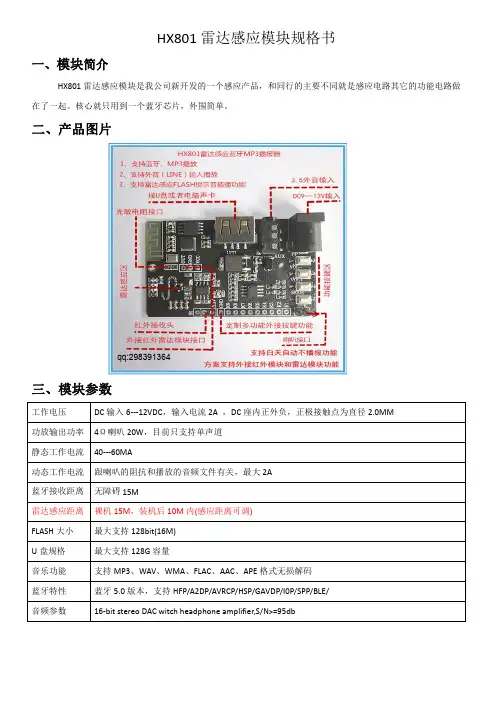
HX801雷达感应模块规格书一、模块简介HX801雷达感应模块是我公司新开发的一个感应产品,和同行的主要不同就是感应电路其它的功能电路做在了一起。
核心就只用到一个蓝牙芯片,外围简单。
二、产品图片qq:298391364三、模块参数工作电压DC输入6---12VDC,输入电流2A,DC座内正外负,正极接触点为直径2.0MM功放输出功率4Ω喇叭20W,目前只支持单声道静态工作电流40---60MA动态工作电流跟喇叭的阻抗和播放的音频文件有关,最大2A蓝牙接收距离无障碍15M雷达感应距离裸机15M,装机后10M内(感应距离可调)FLASH大小最大支持128bit(16M)U盘规格最大支持128G容量音乐功能支持MP3、WAV、WMA、FLAC、AAC、APE格式无损解码蓝牙特性蓝牙5.0版本,支持HFP/A2DP/AVRCP/HSP/GAVDP/I0P/SPP/BLE/音频参数16-bit stereo DAC witch headphone amplifier,S/N>=95db四、模块功能说明1、支持蓝牙连手机音乐播放2、支持U盘MP3播放3、支持外音输入播放4、支持内置FLASH感应播放5、支持红外摇控器6、支持雷达感应白天不工作,晚上感应工作,只要在指定位置加一个光敏电阻就可以实现7、支持9路一对一按键操作文件夹播放(该功能需要定制)8、支持4个按键操作,1、MODE键,2、音量加/下一曲键,3、音量减/上一曲键4、播放/暂停键五、产品特点1、雷达感应电路和语音板放在了一起,物料成本和生产成本明显降低2、感应原理是多普勒效应原理,有穿透非金属物质的特性,成品面板可以不用开窗,保护了产品的美观3、方案支持蓝牙、U盘、外接音频输入播放功能4、产品集成度高,整体使用外围元件少5、方案支持白天不播报功能,只需增加一个光敏电阻即可6、方案定制灵活,外接按键可以支持9路一对一文件夹播放,也可定制支持蓝牙串口和BLE数传、SPP透传7、感应角度为180度8、支持蓝牙音乐播放的语音播报器,这个功能目前大多数类似产品不支持这个功能注意:目前方案只支持感应播放内置FLASH指定文件夹音频文件,其它设备不支持感应播放,需定制才可能实现。
12Ti 警告:不遵守适用的说明以及不当地操作设备都可能导致严重或致命的伤害。
警告:不遵守适用的说明以及不当地操作设备都可能导致人身伤害和/或财产损失。
注意:请特别注意带有此符号的部分。
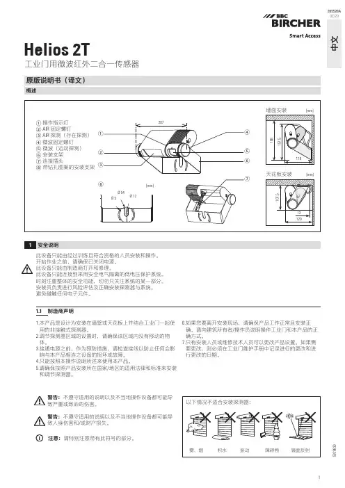
工业门用微波红外二合一传感器原版说明书(译文)概述1安全说明中文395520A 02/20此设备只能由经过训练且符合资格的人员安装和操作。
开始作业之前,请确保已关闭电源。
此设备只能由制造商打开和修理。
此设备只能连接到采用安全电气隔离的低电压保护系统。
时刻注重整体的安全功能,切勿只关注系统的某一部分。
安装员负责进行风险评估及正确安装探测器与系统。
避免碰触任何电子元件。
1.1 制造商声明1. 本产品是设计为安装在墙壁或天花板上并结合工业门一起使用的非接触式探测器。
2. 调节探测器区域的设置时,请确保该区域内没有移动的物体。
3. 接通电源之前,作为预防措施,请检查接线以防止任何会影响与本产品相连之设备的损坏或故障。
4. 只能按照本操作说明所述来使用本产品。
5. 请确保按照产品安装所在国家/地区的适用法律和标准来安装和调节探测器。
6. 如果您要离开安装现场,请确保产品工作正常且安装正确。
请向建筑所有者/操作员说明操作工业门和本产品的正确方式。
7. 只有安装人员或维修技术人员可以更改产品设置。
如果需要更改,则必须在工业门维护手册中记录进行的更改和进行更改的日期。
592883021234[mm]iGoogle Play 和 Google Play 徽标是 Google LLC 的商标。
App Store 是 Apple Inc. 的服务标志。
*B luetooth ® 文字标志和徽标是 Bluetooth SIG, Inc. 拥有的注册商标,BBC Bircher AG 对此类标志的任何使用均已获得许可。
使用 App 之前一旦使用此移动 App ,即表示您同意指定的授权和数据隐私政策,并同意使用智能手机/平板电脑定位信息和 Bluetooth* 功能。
高可靠微波感应人体传感器这里介绍的微波感应控制器和市场上常见的简易型微波感应控制器相比较,因为采用专用的微处理集成电路HT7610A,不但检测灵敏度度高,探测范围宽,而且工作非常可靠,误报率极低,能在-25~+45度的温度范围内稳定工作,最适和在中、高档防盗报警系统中作人体移动检测传感头使用。
1。
工作原理微波感应控制器使用直径9厘米的微型环形天线作微波探测,其天线在轴线方向产生一个椭圆形半径为0~5米(可调)空间微波戒备区,当人体活动时其反射的回波和微波感应控制器发出的原微波场(或频率)相干涉而发生变化,这一变化量经HT7610A进行检测、放大、整形、多重比较以及延时处理后由白色导线输出电压控制信号。
高可靠微波感应控制器内部由环形天线和微波三极管组成一个工作频率为2.4GHz的微波振荡器,环形天线既做发射天线也可接收由人体移动而反射的回波。
内部微波三极管的半导体PN结混频后差拍检出微弱的频移信号(即检测到人体的移动信号) ,微波专用微处理器HT7610A首先去除幅度太小的干扰信号只将一定强度的探测频移信号转化成宽度不同的等幅脉冲,电路只识别脉冲足够宽的单体信号,如人体、车辆其鉴别电路才被触发,或者两秒内有2~3个窄脉冲,如防范边沿区人走动2~3步,鉴宽电路也被触发,启动延时控制电路工作。
如果是较弱的干扰信号,如小体积的动物,远距离的树木晃动、高频通讯信号、远距离的闪电和家用电器开关时产生的干扰予以排除。
最后输HT7610A鉴别出真正大物体移动信号时,控制电路被触发,输出2秒左右的高电平,并有LED2同步显示,输出方式为电压方式,有输出时为高电平(8伏以上),没有输出时为低电平。
微波专用的微处理器HT7610A的时钟频率为16KH,当初次加电时,系统将闭锁60秒,期间完成微处理器的初始化并建立电场,这时LED 闪亮60秒后熄灭,系统自动进入检测状态,当检测到有效信号时,将有2秒信号输出,并由指示灯LED同步点亮。
Table of Contents1.Overview42.Electrical characteristics and parameters52.1Detection angle and distance52.2.Electrical characteristics52.3.RF performance53.Module dimensions and pin description63.1Module size package63.2.Pin description63.2Using the wiring diagram74.Main working properties74.1Radar module operating range74.2.Main functions and performance85.How the radar works and how it is installed95.1.Vertical mounting mode95.2.Tilt mounting mode105.3.Horizontal mounting mode106.Typical applications101.OverviewRadar module MR60FDA1utilizes60G millimeter wave technology to detect human motion and posture,enabling the fall monitoring function.This module utilizes an FMCW radar system to enable wireless detection of personnel status at a particular location. Radar modules have the following characteristics:1.Realize the function of personnel position detection and report the statistics;2.Restrict the detection object to objects with biological characteristics(moving orstationary)and eliminate interference from other inanimate objects in theenvironment;3.This module is capable of eliminating the effects of nonliving objects and canalso detect moving nonliving objects;4.It supports secondary development and can adapt to a variety of applications;5.A universal UART communication interface protocol;6.Four groups of input and output are reserved for user-defined input and output orsimple interface simulation;7.The power output is not significant enough to course harm to the human body.2.Electrical characteristics and parameters2.1Detection angle and distanceNote:[1][2]Radar hang height2.8m,radius of radar projection.2.2.Electrical characteristics2.3.RF performance3.Module dimensions and pin description3.1Module sizepackageFig.1Schematic diagram of the radar module structure3.2.Pin descriptionInterface 213V3 3.3VOutput power 2GND Ground 3SL Reserved 4SD Reserved 5GP1Spare expansion pins 6GP2Spare expansion pins 7GP3Spare expansion pins 8GP4Spare expansion pins3.2Using the wiring diagramFig.2Schematic diagram of the radar module and peripheralconnections4.Main working properties4.1Radar module operating rangeThe beam coverage of the radar module is shown in the figure below.It covers a three-dimensional sector area having a horizontal angle of 100degrees and 100degrees incline.Due to the characteristics of the radar’s beam,it has a long-range coverage in the direction normal to the antenna surface but a short-range if it deviates from the normal direction of the antenna surface.In addition,when the radar is mounted on top or inclined,its range will be reduced.This is due to the influence of its beam and effective radiation space.This should be put into consideration during usage.4.2.main functions and performance1.Main functions and performancea.Fall detection functioni.Distance detection1.Radar projection radius when installed on the top≤2m2.Inclined installation,radar projection distance≤4mii.Accuracy:≥90%2.Presence awarenessa.Detection distance:projection radius≤3mb.Accuracy:≥90%3.Motion detection functiona.Motion triggerb.Motion direction and position perception5.How the radar works and how it is installed5.1.vertical mounting modeThe radar is installed on the roof and shines vertically downward.Radar installation height is h=2.4m~3M.With a radius of radar beam coverage area of R within the radar projection area,it is possible to further divide the projection area into areas for fall detection,presence detection,and motion detection.The Figure below illustrates a schematic diagram of the area.(a)Radar projection schematic(b)Schematic diagram of beam splitting5.2.Tilt mounting modeCertain scenarios require the radar to be installed obliquely,such as in a corner.For this type of installation method,the home gyroscope sensor on the radar determines the inclination of the radar and assists the radar in adjusting the angle.5.3.Horizontal mounting modeConsidering the number of channels of the current radar chip,the fall detection function is not considered for horizontal installation mode.6.Typical applications1.The product is appropriate for small-area scenes,including those in the bathroom,the bedroom,and the living room.2.It is suitable for both inclined and top mounting.3.The product is suitable for single or double occupancy.4.The product must eliminate interference actions in consideration of applicationscenarios.。
e 602-II Instruction manualDelivery includes Delivery includes• e 602-II• pouch• quick guide• safety guideProduct overview1. sound inlet basket2. XLR-3 connector3. integral stand mountInstallationInstallationAttaching the microphoneScrew the microphone’s built-in mount onto a sufficiently stable microphone stand.Connecting the microphoneConnect the XLR-3 socket of the microphone cable (optional accessories) to the XLR-3 socket of the microphone.OperationOperationPositioning the microphone on a kick drumIt is vital to observe the following notes:Position Resulting sound CommentaryAmuch attack little resonance dryPosition the microphone at a distance of a few centi-meters from the batter head.Bless attackmuch resonancesmooth and voluminous Position the microphone at the level of the resonant head.Cless AttackPosition the microphone in the middle between thebatter head and the resonant head.For less attack in all three positions, turn the microphone away from where the beater strikes.A B CPositioning the monitor loudspeakersTo prevent feedback and crosstalk, postion your monitor loudspeakers in the angle area of the highest cancellation of the microphone (approx. 180°).Cleaning and maintaining the e 602-IICleaning and maintaining the e 602-IICAUTIONLIQUIDS CAN DAMAGE THE ELECTRONICS OF THE PRODUCT!Liquids entering the housing of the product can cause a short-circuit and damage the electronics.Keep all liquids away from the product.Do not use any solvents or cleansing agents.Disconnect the products from the power supply system and remove rechargeable batteries and batteries before you begin cleaning.Clean all products only with a soft, dry cloth.Cleaning the sound inlet basket of the microphone moduleUnscrew the sound inlet basket.Remove the foam insert from the sound inlet basket.Use a slightly damp cloth to clean the sound inlet basket from the inside and ouside.If necessary, clean the foam insert with a mild detergent or replace the foam insert.Dry the foam insert.Reinsert the foam insert.Replace the sound inlet basket on the microphone head and screw it tight.SpecificationsSpecificationsTransducer principle dynamic Frequency response 20 - 16,000 H z Pick-up patterncardioidSensitivity (free field, no load)0.9 mV/Pa (at 50 Hz) 0.25 mV/Pa (at 1 kHz)Nominal impedance (at 1 kHz)350 ΩMin. terminating impedance 1 kΩConnector XLR-3Dimensions Ø 60 mm, length 153 mm Weight318 gPolar pattern125 Hz 250 Hz 500 Hz 1,000 Hz 2,000 Hz 4,000 Hz8,000 Hz 16,000 Hz30°0°180°150°120°60°90°0510152025dB30°0°180°150°120°60°90°Frequency response-40-50-60-70-80-90501002005001,0002,0005,00010,00020,000H zdBV 0°, 1 m 0°, 5 cmOverview of applicationsConnector assignmentUNBALANCEDBALANCEDOverview of applicationsPrimary application Secondary application。
深圳市海凌科电子有限公司HLK-LD2410B人体存在感应模组说明书目录1产品简介 (3)2产品特点和优势 (4)2.1特点 (4)2.2方案优势 (5)3应用场景 (6)4硬件说明 (7)4.1外形尺寸 (7)4.2引脚定义 (7)5使用和配置 (8)5.1典型应用电路 (8)5.2配置参数的作用 (8)5.3可视化配置工具说明 (9)5.4安装方式和感应范围 (10)5.5安装条件 (12)6蓝牙使用说明 (13)6.1安装软件 (13)6.2使用方法 (13)6.3蓝牙密码 (14)6.4OTA升级 (14)6.5蓝牙通讯协议 (16)6.6再次打开蓝牙 (17)7性能和电气参数 (17)8天线罩设计指南 (18)8.1天线罩对毫米波传感器性能的影响 (18)8.2天线罩的设计原则 (18)8.3常见材料 (18)9修订记录 (20)10技术支持和联络方式 (21)1产品简介LD2410B是海凌科电子开发的一款高灵敏度的24GHz人体存在状态感应模组。
其工作原理是利用FMCW调频连续波,对设定空间内的人体目标进行探测,结合雷达信号处理、精确人体感应算法,实现高灵敏度的人体存在状态感应,可识别运动和静止状态下的人体,并可计算出目标的距离等辅助信息。
本产品主要应用在室内场景,感知区域内是否有运动或者微动的人体,实时输出检测结果。
最远感应距离可达6米,距离分辨率0.75m。
提供可视化的配置工具,可轻松配置感应距离范围、不同区间的感应灵敏度和无人延时时间等,适应不同的具体应用需求。
支持GPIO 和UART输出,即插即用,可灵活应用于不同的智能场景和终端产品。
高度1.5~2米图1使用方式图示2产品特点和优势2.1特点●即插即用,简易装配方式●最远感应距离为可达6米●探测角度大,覆盖范围可达±60度●区间内准确识别,支持感应范围划分,屏蔽区间外干扰●可以通过蓝牙或串口实现多级智能调参,满足场景变化需求●可视化调试和配置工具●小巧简化,最小尺寸仅为7mmx35mm●支持挂顶、挂壁等多种安装方式●24GHz ISM频段,可通过FCC和CE频谱法规认证●极致性价比之选2.2方案优势LD2410B人体感应模组采用24GHz毫米波雷达传感器技术,和其他方案对比,在人体感应应用上有着明显的优势:1.除了对运动人体感应灵敏外,对于传统方案无法识别的静止、微动、坐卧人体也都可灵敏感应到;2.有良好的环境适应性,感应效果不受温度、亮度、湿度和光线波动等周围环境影响;3.有良好的外壳穿透性,可隐藏在外壳里面工作,无需在产品表面开孔,提高了产品美观度;4.可灵活配置最远感应距离和每个距离门上的灵敏度,实现灵活精细的个性化配置;5.带有蓝牙功能,可以无需接住串口,直接使用APP调试雷达参数好一般弱图2毫米波雷达方案和其他方案对比3应用场景LD2410B人体感应模组对运动、微动和站立、坐卧的人体均可进行探测识别,支持多级调参,可广泛应用于AIoT 各种场景,常用类型如下●人体感应灯控感知所在空间是否有人存在,自动控制灯光,如公共场所照明设备、各类感应灯、球泡灯等。
主流微波雷达人体红外感应LD602芯片规格书
一、概括
LD602是一款专为热释电红外传感器信号放大及处理输出的数模混合专用芯片,内部集成了运算放大器、双门限电压比较器、参考电压源、延时时间定时器和封锁时间定时器及状态控制器等,专用于防盗报警系统、人体门控制装置、照明控制开关等场合。
LD602电源工作电压为+3V~+6V,采用CMOS工艺数模混合相结合的集成电路,8个引脚数封装设计,降低了外围电路元件数和整体成本,节省了PCB板空间。
二、应用场合
■红外报警器/语音迎宾器■红外感应灯
■自动门控控制■自动灯光照明系统■微波雷达感应开关■森林防火报警器
三、主要特点
●静态功耗小,3V工作电源时功耗小于45uA,5V工作电源时功耗小于75uA,非常适合电
池供电系统应用,QQ:298391364
●高输入阻抗运算放大器,可与多种传感器匹配,进行信号处理,可作为微波人体感应处理
芯片
●双向鉴幅器,可有效抑制干扰
●内置参考电压,供内部比较器和运放的参考电压
●内设延时时间定时器和封锁时间定时器,改变振荡器频率即可设定定时延时时间
●8脚红外热释电专用芯片,外围电路简单,成本低
●外围元器件少,只需配置第一级运放的增益和振荡器的RC器件即能可靠工作
●工作电压+3V~+6V
●封装形式SOP8
●包装方式管装
四、引脚定义
五、引脚说明
引脚号引脚名功能描述1OUT1内部第一级运放的输出端
2IN1内部第一级运放的输入端
3VC 触发禁止端
当该脚VC电压<0.2Vdd时,禁止触发,即输出信号OUT一直保持低电平
当该脚VC电压>0.2Vdd时,允许触发,即输出状态跟随输入信号触发
4A 可重复触发和不可重复触发控制端当A=“1”时,允许重复触发
当A=“0”时,不可重复触发
5GND芯片地
6OUT2控制信号输出端,高电平有效输出
7CT 振荡器控制端,该脚需对地外接一个振荡电容和对Vdd外接一个上拉电阻
8VIN电源输入端,范围3V~6V
六、经典常用电路
红外感应应用电路
微波人体感应方案
其中Q2为微波三极管,天线为板载微波天线。
微波感应不受环境,温度影响,比较可靠,我司已有成熟设计方案,如需详细图纸和layout可以咨询我司销售获取。
芯片结构图
七、绝对最大额定值
符号参数名称测试条件最小最大单位VDD电源输入VDD相对GND电压-0.37V IO输入输出端IO口相对GND电压-0.37V TA环境温度-4585℃TSTR存储温度-65125℃TL焊接温度10秒-300℃ESD静电击穿电压-4000V 注:超出所列的极限参数可能导致芯片内部永久损坏或性能劣化,在极限的条件下长时
间运行会影响芯片的可靠性。
八、电学特性参数
符号参数名称测试条件最小典型最大单位VDD工作电源VDD输入电压36V
ICC静态工作电流VDD=5V-6075uA VDD=3V-3045uA
VOS运放输入失调电压VDD=5V-510mV IOS运放输入失调电流VDD=5V--100nA AVD运放开环电压增益VDD=5V60--db VOPAH运放输出高电平VDD=5V,ILOAD=5uA 4.5 4.85-V VOPAL运放输出低电平VDD=5V,ILOAD=5uA--0.1V
VOH OUT端输出高电平VDD=5V,IOUT=-10mA 4.3 4.6-V VDD=3V,IOUT=-3mA 2.3 2.6-V
VOL OUT端输出低电平VDD=5V,IOUT=-10mA-0.30.6V VDD=3V,IOUT=-3mA-0.30.6V
VCH VC端输入高电平VDD=5V 1.1--V VDD=3V0.7--V
VCL VC端输入低电平VDD=5V--0.5V VDD=3V--0.4V
VAH A端输入高电平VDD=5V 3.55-V VDD=3V23-V
VAL A端输入低电平VDD=5V-00.7V VDD=3V-00.5V
九、应用信息
1、振荡器工作频率计算
LD602仅需一个外接电容CT和一个上拉电阻RT即可设置振荡器的工作频率,上电后通过上拉电阻RT对CT电容进行充电,当电容上电压充电到0.6Vdd电压时,双门限比较器动作开启内部下拉27K电阻对CT进行放电,当电容上电压放电到0.4Vdd时,双门限比较器动作关闭内部下拉电阻,CT电容再一次通过上拉电阻RT进行充电到0.6Vdd,这样周期性的对电容进行充放电,从而得到稳定的工作振荡频率,近似的工作频率和电阻电容之间关系由公式TOSC=0.4CTRT*RT/RT-27决定,(电阻单位为K,电容单位为nF,Tosc单位为uS),频率由f=1⁄TOSC确定,如RT=680K,CT=1nF时,对应的延时时间约为30秒。
选择上拉电阻RT时,需大于80K以上的电阻。
(内置27K电阻可能会在后续版本中修改,请关注最新版的Datasheet).
振荡器内部工作原理
2、触发延时时间定时器和触发封锁时间定时器
LD602定义触发延时定时器的时间为Tx,触发封锁时间定时器的时间Ti,两者的比例系数为K,即K=Tx/Ti,LD602的K值默认为14,封装为SOP8封装,为适应不同的应用场合,如有其他K值需要(3<K<48)请咨询本司销售。
触发延时时间定时器主要用于信号触发后进入持续输出高电平时间阶段,其定时时间约为100000个Tosc时钟周期,即Tx为固定的100000TOSC,经100000个Tosc时钟周期后,OUT引脚开始输出低电平进入触发封锁时间定时器阶段,触发封锁阶段OUT引脚是持续输出低电平,但振荡器继续工作直至Ti结束。
触发延时和封锁延时
3、可重复触发和不可重复触发功能
当引脚A=”0”时,工作方式设置为不可重复触发模式,所谓不可重复触发模式指的是当Vc高电平有效时,触发信号Vs的第一个上升沿跳变将使OUT脚输出高电平,芯片进入Tx触发延时定时和Ti触发封锁定时阶段,在此阶段内如果再来Vs触发信号,Vs触发信号
将是无效的,一直到Tx和Ti定时结束,触发信号Vs重新有效
不可重复触发模式
当引脚A=”1”时,工作方式设置为可重复触发模式,所谓可重复触发模式指的是当Vc
高电平有效时,触发信号Vs的第一个上升沿跳变将使OUT脚输出高电平,芯片进入Tx触
发延时定时阶段,在Tx阶段内Vs一直有效,在此阶段内如果有Vs上升沿跳变再次触发,
芯片将重新计数Tx触发延时定时,一直到Tx定时结束才使Vs触发信号无效进入Ti封
锁定时阶段,在Ti封锁定时结束后,触发信号Vs才重新有效。
可重复触发模式
4、PIR红外热释电应用建议
一般最常用的热释电红外传感器的灵敏度是沿长方形方向横向移动才是最高的,所以为了在各个方向灵敏度相近,成品在装配布置时,建议采用45度安装,并且使用菲涅尔(Fresnel)透镜。
热释电红外传感器容易受各种热源,光源,辐射,环境温度等干扰,为了尽量避免误触发,请尽量远离火源、空调、窗口等。
在电路布线上,PIR与其他器件的连线越短越好,多层板布线时,连线下方不要走线,尤其不能走大电流的走线。
PIR感应部分的电路要单独隔离并有单独的接地,探头电源上接一个100nF的电容到地,并尽量与探头电源接近。
如果允许,在电源上串联一个47K电阻,并且并联一个100uF的电解电容,在D/S之间接一个200pF 电容等各种方法,尽量避免干扰信号进入处理芯片。
十、封装消息
LD602用的是标准的SOP8通用封装,在立创商城下载一个SOP8封装就可以用。