9020-9010 说明书中文
- 格式:doc
- 大小:558.50 KB
- 文档页数:19
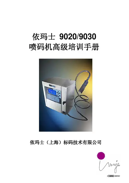
依玛士 9020/9030 喷码机高级培训手册依玛士(上海)标码技术有限公司目 录一.公司简介及安全事项--------------------------------------41-1 公司及产品简介1-2 设备保修期内、外的服务1-3 喷码机使用安全注意事项1-4 操作中的注意事项二.喷码基本原理----------------------------------------------112-1 点阵成字原理2-2 喷头工作原理三、喷码机结构-------------------------------------------------133-1 喷码机外观3-2 喷码机内部结构3-3 喷头结构3-4 控制面板说明四、喷码机工作原理----------------------------------------- -59 油墨管路工作原理五、日常开关机步骤--------------------------------- ----------545-1 日常开机步骤5-2 油墨和添加剂液位报警5-3 墨线开启不成功的处理5-4 日常关机步骤六、信息编辑----------------------------------------------------356-1 新建一条信息---- F26-2 选择字形(图案或特殊字体)6-3 固定字符的输入(英文与数字等)6-4 变量的输入(日期)6-5 变量的输入(计数器)6-6 信息参数的修改6-7 信息保存与关闭6-8 选择喷印信息--- F16-9 编辑当前信息的内容--- F36-10 拼音输入汉字6-11 修改当前信息的参数--- F46-12 计数器的显示与复位--- F5 七、机器维护保养----------------------------------------------497-1 维护保养的重要性7-2 消耗品与机器维护7-3 保养计划7-4 清洁机器7-5 清洗油墨管路并更换过滤组件7-6 整机维护功能介绍八、电气连接----------------------------------------------------548-1 工业接口板概貌8-2 传感器接线8-3 同步器接线8-4 报警输出8-5 交换数据-----PCMCIA卡的应用九、故障处理----------------------------------------------------689-1 喷头盖未合(84)9-2 充电检测故障(81&82)9-3 断点调整9-4 高压故障(87&86)9-5 回收故障(85)9-6 喷印不良9-7 浓度故障(70&83)9-8 无故障显示,但不喷印9-9 喷印速度报警(40&48)9-10油墨管路故障(71~79)附录----------------------------------------------------------------76 9020/9030 主动性维护服务协议一.公司简介及安全事项1-1 公司及产品简介一家跨国专业公司 依玛士公司是集科研、开发、生产为一体的跨国专业公司,总部及主要生产基地位于法国,在全球设有32个分公司、60个商务代表处。
Dell OptiPlex 9020 AIO 用户手册管制型号: W04C管制类型: W04C002注、小心和警告注: “注”表示可以帮助您更好地使用计算机的重要信息。
小心: “小心”表示可能会损坏硬件或导致数据丢失,并说明如何避免此类问题。
警告: “警告”表示可能会造成财产损失、人身伤害甚至死亡。
© 2013 Dell Inc. 保留所有权利。
本文中使用的商标:Dell™、DELL 徽标、Dell Precision™、Precision ON™、ExpressCharge™、Latitude™、Latitude ON™、OptiPlex™、Venue™、Vostro™和 Wi-Fi Catcher™是 Dell Inc. 的商标。
Intel®、Pentium®、Xeon®、Core™、Atom™、Centrino®和 Celeron®是 Intel Corporation 在美国和/或其他国家或地区的注册商标。
AMD®是注册商标,AMD Opteron™、AMD Phenom™、AMD Sempron™、AMD Athlon™、ATI Radeon™和 ATI FirePro™是 Advanced Micro Devices, Inc. 的商标。
Microsoft®、Windows®、MS-DOS®、Windows Vista®、Windows Vista 开始按钮和 Office Outlook®是 Microsoft Corporation 在美国和/或其他国家或地区的注册商标。
Blu-ray Disc™是 Blu-ray Disc Association (BDA) 拥有的商标,经其许可在磁盘和播放器上使用。
Bluetooth®文字标记是 Bluetooth® SIG, Inc. 拥有的注册商标,Dell Inc. 经其许可使用这些标记。
为了创造更加美好的环境请您协作首先对您使用 Brother 产品表示衷心的感谢!Brother 公司致力于关爱地球环境,制定了“从产品开发到废弃,关爱地球环境”的基本方针。
当地的公民在环境保护活动中也应该对当地社会、环境二方面尽每个人的微薄之力。
因此,希望您能配合这个计划,作为环境保护活动的一环,在平时处理废弃物的时候能多加注意。
1不用的包装材料,为了能再次回收利用,请交付给当地相关回收公司进行处理。
2废弃耗材的处理,应遵守相关的法律和规定。
请根据相关法律和规定妥当处理。
3产品保养或修理需要更换零部件时,有不需要的电路板和电子零件,以及产品废弃时,请作为电子废弃物处理。
4关闭本产品电源开关后,在拨下电源插头的情况下耗电量是零。
5本产品中的部分零部件可以用于同一工厂生产的同系列机型上。
注:零部件的更换请联系就近的 Brother 维修站。
©2009 Brother Industries, Ltd.编辑及出版说明本说明书在兄弟工业株式会社监督下编辑出版,包含最新的产品说明和规格。
本说明书内容及产品规格如有更改,恕不另行通知。
Brother 公司保留对包含在本说明书中的产品规格和内容作出更改的权利,恕不另行通知,同时由于使用本说明书包含的内容所造成的任何损坏 (包括后果),包括但不局限于本出版物的排版及其他错误,Brother 公司将不承担任何责任。
i目录第 I 部分概述1常规信息2使用本说明书 (2)本说明书中使用的符号和惯例 (2)获取软件使用说明书和网络使用说明书 (3)查看说明书 (3)获取 Brother 技术支持(适用于 Windows®) (5)操作面板概述 (6)数据指示灯显示 (8)2装入纸张和原稿9装入纸张和打印介质 (9)将纸张装入标准纸盒 (9)将纸张装入手动进纸槽 (11)非打印区域 (15)适用的纸张和其他打印介质 (16)推荐的纸张和打印介质 (16)纸张的类型和尺寸 (16)处理和使用特殊纸张 (18)装入原稿 (21)使用自动进稿器 (ADF) (21)使用平板扫描器 (22)3常规设置23纸张设置 (23)纸张类型 (23)纸张尺寸 (23)音量设置 (23)蜂鸣器音量 (23)环保性能 (24)省墨 (24)休眠时间 (24)液晶显示屏对比度 (24)ii第 II 部分复印4复印26如何复印 (26)复印模式 (26)单页复印 (26)多页复印 (26)停止复印 (26)复印选项 (临时设置) (27)放大或缩小复印图像 (27)提高复印质量 (28)使用选项键 (29)身份证双面复印 (30)使用自动进稿器排序复印件 (30)调整对比度、色彩和亮度 (31)N 合 1 复印 (页面布局) (32)内存已满信息 (33)第 III 部分软件5软件和网络功能36如何阅读 HTML 格式的使用说明书 (36)Windows® (36)Macintosh (36)第 IV 部分附录A安全及法规38选择安放设备的位置 (38)安全使用设备 (39)重要安全说明 (42)断开设备电源 (43)局域网连接 (44)无线电干扰 (44)复印法规限制 (45)Libtiff 版权与许可 (46)商标 (47)B选配件48内存条 (48)安装扩展内存 (48)iiiC故障排除和日常维护50故障排除 (50)如果使用设备时出现问题 (50)提高打印质量 (55)错误和维护信息 (63)原稿卡纸 (69)卡纸 (70)日常维护 (75)清洁设备的外部 (75)清洁平板扫描器 (76)清洁 LED 灯 (阵列) (77)清洁电晕丝 (78)清洁硒鼓单元 (79)清洁送纸辊 (84)校准 (84)自动配准 (85)手动配准 (85)更换耗材 (86)更换墨粉盒 (88)硒鼓单元 (93)更换转印带单元 (98)更换废粉仓 (102)更换需定期维护的零件 (107)设备信息 (107)检查序列号 (107)检查页码计数器 (107)用户设置列表 (107)网络配置列表 (108)检查零件的剩余寿命 (108)重置功能 (108)如何重置设备 (109)包装和运输设备 (109)D菜单和功能114屏幕编程 (114)功能表 (114)内存存储 (114)菜单键 (114)如何进入菜单模式 (115)功能表 (116)输入文本 (123)ivE规格124常规 (124)打印介质 (126)复印 (127)扫描 (128)打印 (129)接口 (130)计算机要求 (131)耗材 (133)有线以太网 (134)F术语表137 G索引138vvi概述常规信息2装入纸张和原稿9常规设置231使用本说明书感谢您购买 Brother 设备!阅读此说明书将有助于您充分使用本设备。

使用说明书Model 9010微电脑处理溶氧/温度可携式测量仪器JENCO ELECTRONICS,LTD.上海任氏电子有限公司敬告用户1.请在使用仪器前详细阅读本使用说明书。
2.仪器使用一年后,必须送计量部门或有计量检验资格的单位复检合格后方可使用。
产品检视小心地打开包装,检视仪器及配件是否有因运送而损坏,如有发现损坏,请即刻通知任氏的代理商,幷以原包装寄回送检。
概述Model 9010 型仪器是一种携带型的、高精度的溶氧测量仪。
z以微电脑为中心设计而成。
z可测量溶氧(含压力, 盐度补偿)及温度。
z可对探棒的参数做校正,使用单点校正。
z提供不同模式显示―溶氧(%),溶氧(ppm)及温度(℃)。
z提供一装有潮湿泡棉的塑料校正瓶,做为校正,运送及存放探棒之用。
z电源使用9V电池,长电池寿命。
z使用按键时会有声音回馈。
z提供”LO BAT”(电力不足)显示,提醒使用者更换电池。
z所有探棒头都使用舍弃式。
1仪器使用方法一、外壳此外壳可以防水 , 若不小心泼或浸到水,请尽快用水洗净并用布擦拭干净,等完全干后若仍不能工作时,请尽速送回任氏维修。
3.盐度及单位4.压力及单位5.溶氧值显示6.溶氧单位指示7.温度及单位指示三、按键1.ON/OFF键 : 开机及关机键2.MODE键: 在正常模式下,按此键会改变溶氧以%(空气饱和)或以ppm显示。
在校正模式下,会跳离目前的校正参数(不储存) , 到下一个校正参数。
23.CAL键: 在正常模式下 , 按下此键会进入校正模式。
4.ENTER键 : 在校正模式下 , 按下此键将会储存新的参数。
5.△键: 在校正模式下 , 按下此键可增加参数值。
键: 在校正模式下 , 按下此键可减少参数值。
6.▽ 四、更换电池2.取出9V电池并装上新电池,更换时,注意电池极性放置要正确。
3.放回防水圈和电池盖,并将刚取出的两个螺丝锁紧即可。
3五、仪器的开机及关机当仪器不使用时,要按 ON/OFF 键关机,以延长电池寿命,当开机时,LCD会显示目前的温度并处于待测状态。
使用说明
安全
喷码机的启动/停止
介面介绍
信息的选择和显示
信息的打印
信息的更改
耗材的检查和更换
喷头的保养
故障和报警
安全
E
___________________________________________________________________________________
使用说明
安全使用说明
安全
使用说明
安全使用说明
安全
使用说明
安全使用说明
安全
使用说明
9020 - 9030 使用说明
喷码机的启动
喷码机关闭■
日常关闭
使用说明
介面介绍
信息选择■
选择喷印信息
使用说明
显示信息
使用说明
信息打印
15
“PARIS”这条信息喷印就绪
使用说明
信息的更改
使用说明
耗材
17油墨添加剂
盒内余量水平
使用说明
喷头的保养
使用说明
喷头的保养(续)清洗喷头仔细将其干燥,然后
使用说明
故障与报警
使用说明
照片和图示未在细节上结合描述。
明。
马肯依玛士保留修改产品规格的权利,恕不提前通知。
禁止以任何形式复制本文档或本文档的部分内容。
原始手册的翻译: 原始手册(法文)可从打印机随附的 CD-ROM 中获得。
使用说明
A39544-A。
Agilent-N9020A使用说明书功能测试XXXN9020A MXA操作手册1功能测试功能测试是对各种仪器参数的测试,这些参数对分析仪是否正常工作具有高度的信心。
建议在进货检验或修理后检查分析仪的运行情况。
测量不确定度分析不适用于功能测试,分析仪应根据比公布规范更宽的限值进行检查。
功能测试旨在使用最小的测试设备,测试分析仪在分析仪规范规定的温度范围内运行的分析仪。
如果测试未通过,则必须运行性能验证测试以确定是否存在问题。
功能测试与性能验证功能测试使用最少的测试设备来检查比性能验证测试小得多的参数范围(以及每个参数的有限数据点)。
功能测试使用比公布规范更宽的限值;测量不确定度分析不适用于功能测试。
注意如果功能测试未通过,则必须运行性能验证测试以确定是否存在问题。
性能验证测试涵盖了广泛的仪器参数,并提供了仪器符合公布规范的最高置信水平。
这些测试可能很耗时,需要大量的测试设备。
本文件内容本章包括以下内容:•“在举行功能测试之前”,(第一要做甚么)。
•“测试设备”(所有测试所需的设备清单)。
随后的章节描述了以下功能测试:•“显示平均噪声级(DANL)”•“频次读数精度”•“二次谐波失真(SHD)•“50 MHz振幅精度”•“50 MHz振幅精度”•“频次相应(平展度)”•“频次相应(平展度)前置放大器开启”•“刻度保真度”•“BBIQ输入频次相应(仅BBA选项),每个功能测试包括:•测试限值(合格/分歧格尺度)•测试说明•测试所需的设备•显示如何连接设备的图•逐步说明•记录测量结果的一个或多个表格在执行功能测试之前1.确保你有合适的测试装备。
2.打开被测单元(UUT)并使其预热(根据仪器规范中的预热要求)。
3.为所需的测试设备留出足够的预热时间(有关预热规范,请参阅单独的仪表文档)。
4.确保分析仪的频率参考设置为内部:a、按,键。
输入/输出更多频率参考输入b、如果软键不显示,请按软键并选择。
内部频率参考内部频率参考5.在仪器预热后,执行自动校准程序:按。
DELLTMTABLE OF CONTENTSOVERVIEWMini Tower Computer (MT) View3-4Desktop Computer (DT) View5-6Small Form Factor Computer (SFF) View7-89-10 Ultra Small Form Factor Computer (USFF) ViewOperating System, Chipset11Processor12Memory13Drives and Removable Storage, System Board Connectors14-15Graphics/Video Controller16External Ports/Connectors16Communications—Network Adapter (NIC), Wireless17Audio and Speakers, Keyboard and Mouse17Security, Service and Support, Software18System Dimensions (Physical)19System Board Connector Maximum Allowable Dimensions19System Level Environmental and Operating Conditions20Power21-22Audio23Communications23-28Graphics/Video Controller29-31Hard Drives32-39 Optical Drive40-42 Media Card Reader 43 BIOS Defaults44 Chassis Enclosure and Ventilation Requirements45 Acoustic Noise Emission Information46-49MINI TOWER COMPUTER (MT) VIEWMT System Board ComponentsDESKTOP COMPUTER (DT) VIEWDT System Board ComponentsSMALL FORM FACTOR COMPUTER (SFF) VIEWSFF System Board ComponentsULTRA SMALL FORM FACTOR COMPUTER (USFF) VIEWUSFF System Board ComponentsMARKETING SYSTEM CONFIGURATIONSNO TE: O ff e rin gs ma y v a ry by c o u nt ry.For mo re i n f o rma ti o n re ga rdi ng the c onfigu ra ti on o f y ou r c om pu ter,c lic k Sta r t>H elp a nd Su ppo r t a nd s elec t th e o p ti on to v i ew i n forma ti o n a bo u t y ou r c ompu t er.OPERATING SYSTEMCHIPSETPROCESSOR1NOTE: Global Standard Products (GSP) are a subset of Dell’s relationship products that are managed for availability and synchro-nized transitions on a worldwide basis. They ensure the same platform is available for purchase globally. This allows customers to reduce the number of configurations managed on a worldwide basis, thereby reducing their costs. They also enable companies to implement global IT standards by locking in specific product configurations worldwide. The following GSP processors identi-fied below will be made available to Dell customers.NOTE: Processor numbers are not a measure of performance. Processor availability subject to change and may vary by region/ country.1 3rd generation CPUs natively support 3 displays with the integrated CPU graphics. Three simultaneous display output requires one DP port witha maximum resolution of 2500x1600 at 60Hz refresh rate and a DP and VGA port with max resolutions of 1920x1200 at 60Hz refresh rates.2 Post launch CPU, available from June for G860; July for G640, i5 3470/S, i5 3570/S, i5 3475S.3 Available at launch, will be replaced in June or July, i5 3470/S replace i5 3450/S; i5 3570/S replace i5 3550/S; G860 replace G850; G640 re-place G630.MEMORYNOTE: Memory modules should be installed in pairs of matched memory size, speed, and technology. If the memory modules are not installed in matched pairs, the computer will continue to operate, but with a slight reduction in performance. The entire memory range is available to 64-bit operating systems.1 To fully utilize 4GB or more of memory requires a 64-bit enabled processor and 64-bit operating system. With 32-bit OS, the total amount of available memory will be less than 4GB. The amount less depends on the actual system configuration.2 1600MHz memory will only perform as 1600MHz memory when 3rd generation CPUs are used. It will perform as 1333MHz memory if 2nd generation i3 2130, i3 2125, i3 2120, G860, G850 CPUs are installed in the system. It will perform as 1066MHz memory if 2nd generation G640,G630 CPUs are installed in the system.DRIVES AND REMOVABLE STORAGE1 For hard drives, GB means 1 billion bytes; actual capacity varies with preloaded material and operating environment and will be less.DRIVES AND REMOVABLE STORAGE1 For hard drives, GB means 1 billion bytes; actual capacity varies with preloaded material and operating environment and will be less.2 Discs burned with this drive may not be compatible with some existing drives and players; using DVD+R media provides maximum compatibility.3 DVD-ROM drives may have write-capable hardware that has been disabled via firmware modifications.4 Dell 19 in 1 Media Card Reader (MCR) is supported via a F5 to F3 bay converter on the MT and DT and requires a slim line optical drive.SYSTEM BOARD CONNECTORSNO TE: S ee De ta i led E n gi n eeri n g Spec i fic a ti o ns fo r ma xi mu m c a rd di men si o n s.1 PCI Slots (Support Standard Rev 2.3)2 PCIe x16 Slots (Support Standard Rev 3.0)3 PCIe x16 (wired x 4), PCIe x1 Slots, miniPCIe (Support Standard Rev 2.0)4 Serial ATA ( 2 ports Support Standard Rev 3.0, the rest of ports Support Standard Rev 2.0)GRAPHICS/VIDEO CONTR OLLERNO TE: M T su p po r ts fu l l h eigh t (FH) c a rds a nd D T a nd S FF su ppo rt s low p rofi l e (LP) c a rd s.EXTERNAL PORTS/CONNE CTORS1This term does not connote an actual operating speed of 1 Gb/sec. For high speed transmission, connection to a Gigabit Ethernet server and network infrastructure is required.COMMUNICATIONS – WIRELESSNO TE : M T su p po r ts fu l l h eigh t (FH) c a rds a nd D T a nd S FF su ppo rt s low p rofi l e (LP) ca rd s.AUDIO AND SPEAKERSKEYBOARD AND MOUSECOMMUNICATIONS - NETWORK ADAPTER (NIC)NO TE : M T su p po r ts fu l l h eigh t (FH) c a rds a nd D T a nd S FF su ppo rt s low p rofi l e (LP) c a rd s.SECURITYSERVICE AND SUPPORTNO TE : Fo r mo r e d eta i l s o n D ell Se rv i c e Pla n s pl ea s e to go to : www.d ell.c om/se rv i c e /se rv i c e_p la nsSOFTWARE1TPM is not available in all countries. Depending on your country regulations, no-TPM system may be available.1For a copy of our guarantees or limited warranties, please write Dell USA L.P., Attn: Warranties, One Dell Way, Round Rock, TX 78682. For more information, visit /warranty.2Service may be provided by third -party. Technician will be dispatched if necessary following phone -based troubleshooting. Subject to parts availability, geographical restrictions and terms of service contract. Service timing dependent upon time of day call placed to Dell. U.S. only.ENVIRONMENTALNO TE : Fo r mo re de ta il s o n Del l E nv i ro nmen ta l fea t u res, p lea s e to go to E nv i ronmen ta l A tt ri bu te s s ec t ion. S ee you r spec i fic re gi o n fo r a v a i la bi li ty.ALL -IN -ONE STANDS AND MOUNTSDETAILED ENGINEERING SPECIFICATIONSSYSTEM DIMENSIONS (P HYSICAL)NO TE: Sy ste m W ei ght a n d Shi ppi n g W e i gh t i s ba sed o n a t y pi c a l c onfi gu ra ti on a nd ma y v a ry ba s ed on P C c o nfigu ra ti o n. A t ypi c a l c o nfigu ra ti o n i nc lu d es: i nt egra ted g ra phi c s, one ha r d dri v e, on e op ti c a l d riv e.SYSTEM BOARD CONNECTOR MAXIMUM ALLOWABLE DIMENSIONSSYSTEM LEVEL ENVIRONMENTAL AND OPERATING CONDITIONSPOWERNO TE: Th ese fo rm fa c to r s u t i li z e a mor e e ffic i ent A c ti v e Pow er Fa c to r Cor re c ti o n (A P FC) pow er su pp l y. Del l rec ommend s o nly Uni v e rs a l Po we r Su ppli es (UPS) b a sed o n Si ne W a v e ou tpu t fo r A P FC PSU s, no t a n a p proxima-ti on o f a Si n e W a v e, Squ a re W a v e, o r qu a si-Squ a re W a v e. I f y ou ha v e qu es ti o ns, p lea s e c onta c t the ma nu fa c-POWERNOTE: These fo rm fac tors utilize a mo re effi cient Active Powe r F acto r C orrec tion (A PFC) po wer su p-ply. De ll reco mmends o nly Uninte rrup tible Po wer Supp lie s (UPS) based on Sine Wave output fo r APFC PSUs, no t an app ro ximation o f a Sine Wave, Sq uare Wave, o r quas i-Square Wave. If you have ques-tions, ple ase contac t the manufac ture to c onfirm the ou tput type.AUDIOINTEGRATED REALTEK ALC269Q HIGH DEFINITION AUDIO MT DT SFF USFF High Definition Stereo support X X X X Number of channels2Number of Bits / Audio resolution16, 20, and 24-bit resolution Sampling rate (recording/playback)Support 44.1K/48K/96K/192 kHz sample rates Signal to Noise Ratio98 dB DAC outputs, 90 dB for ADC inputs Analog Audio X X X X Dolby DigitalTHXDigital out (S/PDIF)Audio Jack ImpedanceMicrophone40K ohm~60K ohmLine-In40K ohm~60K ohmLine-Out100~150 ohmHeadphone1~4 ohmInternal Speaker Power Rating2Watt (peak) / 1Watt (average) COMMUNICATIONS - INTEGRATED LANCOMMUNICATIONS - INTEGRATED LAN (CON.)1 This term does not connote an actual operating speed of 1 Gb/sec. For high speed transmission, connection to a Gigabit Ethernet server and network infrastructure is required.COMMUNICATIONS – NETWORK ADAPTER (NIC)NO TE: M T su p po r ts fu l l h eigh t (FH) c a rds a nd D T a nd S FF su ppo rt s low p rofi l e (LP) c a rd s.1 This term does not connote an actual operating speed of 1 Gb/sec. For high speed transmission, connection to a Gigabit Ethernet server andCOMMUNICATIONS – NETWORK ADAPTER (NIC) (CONT.)1 This term does not connote an actual operating speed of 1 Gb/sec. For high speed transmission, connection to a Gigabit Ethernet server and network infrastructure is required.COMMUNICATIONS – WIRELESSCOMMUNICATIONS – SERIAL PORT PCIE ADD-IN CARDNO TE: M T su p por ts fu l l h eigh t (FH) c a rds a nd D T a nd S FF su ppo rt s low p ro fi l e (LP) c a rd s.GRAPHICS/VIDEO CONTR OLLERNO TE: M T su p po r ts fu l l h eigh t (FH) c a rds a nd D T a nd S FF su ppo rt s low p rofi l e (LP) c a rd s.1 Up to 1.7 GB of system memory may be allocated to support integrated graphics, depending on operating system, system memory size and other factors.2 3rd generation CPUs natively support3 displays with the integrated CPU graphics. Three simultaneous display output requires one DP port with a maximum resolution of 2500x1600 at 60Hz refresh rate and a DP and VGA port with max resolutions of 1920x1200 at 60Hz refresh rates.3 Display output from both onboard and discrete simultaneously if multi display option in BIOS is enabled and Win 7 OS is used.4 For dual graphics card configuration in PCIex16 and PCIex16 (wire as 4), BIOS will disable multi display option automatically and display outputonly from graphics cards.HARD DRIVES11 For hard drives, GB means 1 billion bytes ; actual capacity varies with preloaded material and operating environment and will be less.HARD DRIVES1(CONT.)1For hard drives, GB means 1 billion bytes ; actual capacity varies with preloaded material and operating environment and will be less.HARD DRIVES1(CONT.)1 For hard drives, GB means 1 billion bytes ; actual capacity varies with preloaded material and operating environment and will be less.HARD DRIVES1(CONT.)1 For hard drives, GB means 1 billion bytes ; actual capacity varies with preloaded material and operating environment and will be less.HARD DRIVES1(CONT.)1 For hard drives, GB means 1 billion bytes ; actual capacity varies with preloaded material and operating environment and will be less.HARD DRIVES1(CONT.).1 For hard drives, GB means 1 billion bytes ; actual capacity varies with preloaded material and operating environment and will be less.HARD DRIVES1(CONT.)1 For hard drives, GB means 1 billion bytes ; actual capacity varies with preloaded material and operating environment and will be less.HARD DRIVES1(CONT.)1 For hard drives, GB means 1 billion bytes ; actual capacity varies with preloaded material and operating environment and will be less.OPTICAL DRIVESOPTICAL DRIVES (CONT.)1 Discs burned with this drive may not be compatible with some existing drives and players; using DVD+R media provides maximum compatibility.OPTICAL DRIVES (CONT.)MEDIA CARD READER (MCR)NOTE: Dell 19 in 1 Media Card Reader (MCR) is supported via a F5 to F3 bay converter on the MT and DT and may require a slim line optical drive depending on selectable configuration. MCR is not available on the SFF and USFF chassis.BIOS DEFAULTSCHASSIS ENCLOSURE & VENTILATION REQUIREM ENTSENCLOSURE VENTILATIONIf your enclosure has doors, they need to be of a type that allows at least 30% airflowthrough the enclosure (front and back).ENCLOSURE MINIMUM CLEARANCELeave a 10.2 cm (4 in.) minimum clearance on all vented sides of the computer to permitthe airflow required for proper ventilation.RECOMMENDED ENCLOSUREDo not install your computer in an enclosure that does not allow airflow. This restricts theairflow and impacts your computer’s performance, possibly causing it to overheat.OPEN DESK MINIMUM CLEARANCEIf your computer is installed in a corner, on a desk, or under a desk, leave at least 5.1 cm (2 in.)clearance from the back of the computer to the wall to permit the airflow required for properventilation.REGULATORY COMPLIANCE AND ENVIRONMENTALProduct related conformity assessment and regulatory authorizations including Product Safety, Electromagnetic Compatibility (EMC), Ergonomics, and Communication Devices relevant to this product may be viewed at /regulatory_compliance. The Regulatory Datasheet for this product is located at /regulatory_compliance. Details of Dell's environmental stewardship program to conserve product energy consumption, reduce or eliminate materials for disposal, prolong product life span and provide effective and convenient equipment recovery solutions may be viewed at/environment. Product related conformity assessment, regulatory authorizations, and information encompassing Environmental, Energy Consumption, Noise Emissions, Product Materials Information, Packaging, Batteries, and Recycling relevant to this product may be viewed by clicking the Design for Environment link on the webpage.OPTIPLEX 9010 MTThe Declared Noise Emission in accordance with ISO 9296 for the Dell OptiPlex 9010 MT is as follows:(all values L WAd expressed in bels; 1 bel=10 decibels, re 10-12 Watts)The Declared A-weighted Sound Pressure Level in decibels (re 2x10⁻⁵Pa), at Operator, Bystander, and Desk Side Positions are measured in accordance with ISO 7779 7.6.1, 7.6.2, and C.15.2 and declared in accordance with ISO 9296 for this product is as follows1:1 All tests are conducted according to ISO 7779 and declared according to ISO 9296 except 90% CPU. For this mode, the system CPU was stressed at 90% utilization with no other peripheral device actively seeking. This test mode is not specified in ISO 7779, but was measured using the same microphone distances and measurement techniques defined for the other reported operating modes.OPTIPLEX 9010 DTThe Declared Noise Emission in accordance with ISO 9296 for the Dell OptiPlex 9010 DT is as follows:(all values L WAd expressed in bels; 1 bel=10 decibels, re 10-12 Watts)The Declared A-weighted Sound Pressure Level in decibels (re 2x10⁻⁵Pa), at Operator, Bystander, and Desk Side Positions are measured in accordance with ISO 7779 7.6.1, 7.6.2, and C.15.2 and declared in accordance with ISO 9296 for this product is as follows1:1 All tests are conducted according to ISO 7779 and declared according to ISO 9296 except 90% CPU. For this mode, the system CPU was stressed at 90% utilization with no other peripheral device actively seeking. This test mode is not specified in ISO 7779, but was measured using the same microphone distances and measurement techniques defined for the other reported operating modes.OPTIPLEX 9010 SFFThe Declared Noise Emission in accordance with ISO 9296 for the Dell OptiPlex 9010 SFF is as follows:(all values L WAd expressed in bels; 1 bel=10 decibels, re 10-12 Watts)The Declared A-weighted Sound Pressure Level in decibels (re 2x10⁻⁵Pa), at Operator, Bystander, and Desk Side Positions are measured in accordance with ISO 7779 7.6.1, 7.6.2, and C.15.2 and declared in accordance with ISO 9296 for this product is as follows1:1 All tests are conducted according to ISO 7779 and declared according to ISO 9296 except 90% CPU. For this mode, the system CPU was stressed at 90% utilization with no other peripheral device actively seeking. This test mode is not specified in ISO 7779, but was measured using the same microphone distances and measurement techniques defined for the other reported operating modes.OPTIPLEX 9010 USFFThe Declared Noise Emission in accordance with ISO 9296 for the Dell Optiplex 9010 USFF is as follows:(all values L WAd expressed in bels; 1 bel=10 decibels, re 10-12 Watts)The Declared A-weighted Sound Pressure Level in decibels (re 2x10⁻⁵Pa), at Operator, Bystander, and Desk Side Positions are measured in accordance with ISO 7779 7.6.1, 7.6.2, and C.15.2 and declared in accordance with ISO 9296 for this product is as follows1:1 All tests are conducted according to ISO 7779 and declared according to ISO 9296 except 90% CPU. For this mode, the system CPU was stressed at 90% utilization with no other peripheral device actively seeking. This test mode is not specified in ISO 7779, but was measured using the same microphone distances and measurement techniques defined for the other reported operating modes.。
功能测试安捷伦科技N9020A MXA 操作手册1功能测试功能测试是对各种仪器参数的测试,这些参数对分析仪是否正常工作具有高度的信心。
建议在进货检验或修理后检查分析仪的运行情况。
测量不确定度分析不适用于功能测试,分析仪应根据比公布规范更宽的限值进行检查。
功能测试旨在使用最小的测试设备,测试分析仪在分析仪规范规定的温度范围内运行的分析仪。
如果测试未通过,则必须运行性能验证测试以确定是否存在问题。
功能测试与性能验证功能测试使用最少的测试设备来检查比性能验证测试小得多的参数范围(以及每个参数的有限数据点)。
功能测试使用比公布规范更宽的限值;测量不确定度分析不适用于功能测试。
注意如果功能测试未通过,则必须运行性能验证测试以确定是否存在问题。
性能验证测试涵盖了广泛的仪器参数,并提供了仪器符合公布规范的最高置信水平。
这些测试可能很耗时,需要大量的测试设备。
本文件内容本章包括以下内容:•“在进行功能测试之前”,(首先要做什么)。
•“测试设备”(所有测试所需的设备清单)。
随后的章节描述了以下功能测试:•“显示平均噪声级(DANL)”•“频率读数精度”•“二次谐波失真(SHD)•“50 MHz振幅精度”•“50 MHz振幅精度”•“频率响应(平坦度)”•“频率响应(平坦度)前置放大器开启”•“刻度保真度”•“BBIQ输入频率响应(仅BBA选项),每个功能测试包括:•测试限值(合格/不合格标准)•测试说明•测试所需的设备•显示如何连接设备的图•逐步说明•记录测量结果的一个或多个表格在执行功能测试之前1.确保你有合适的测试设备。
2.打开被测单元(UUT)并使其预热(根据仪器规范中的预热要求)。
3.为所需的测试设备留出足够的预热时间(有关预热规范,请参阅单独的仪表文档)。
4.确保分析仪的频率参考设置为内部:a、按,键。
输入/输出更多频率参考输入b、如果软键不显示,请按软键并选择。
内部频率参考内部频率参考5.在仪器预热后,执行自动校准程序:按。
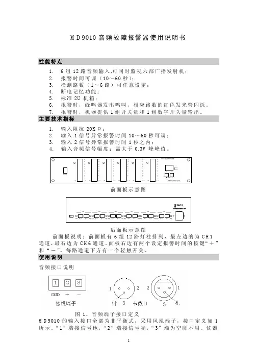
MD9010音频故障报警器使用说明书性能特点1. 6组12路音频输入,可同时监视六部广播发射机;2. 报警时间可调(10~60秒);3. 检测路数(1~6路)可任意设定;4. 断电记忆功能;5. 标准2U机箱;6. 报警时,蜂鸣器发出鸣叫,相应路数的红色发光管闪烁。
7. 报警时,机器提供1组开关量和1组数字开关量输出。
主要技术指标1. 输入阻抗20KΩ;2. 输入1信号异常报警时间10~60秒可调;3. 输入2信号异常报警时间1秒之内;4. 输入音频信号幅度:需大于0.3V峰峰值。
000000前面板示意图后面板示意图前面板说明:前面板有6组12路灯柱排列,最左边的为CH1通道,最右边为CH6通道。
面板右边有两个设定报警时间的按键“+”和“-”。
每路通道下方有一个轻触开关。
使用说明音频接口说明图1、音频端子接口定义MD9010的输入接口全部为非平衡式,采用凤凰端子,接口定义如1所示。
“1”端接信号地,“2”端接信号端,“3”端为空脚不用。
仪器的每个输入通道中,其中:输入1必须接进入发射机前的音频信号;输入2必须接经发射机发射后解调出来的音频信号,如2所示。
两种信号的幅度可由面板上的灯柱直观的显示出来。
调节输入端子旁的微调电位器使输入1,输入2在灯柱上的显示幅度基本一致,并接近顶部。
两种信号经机器内微机处理,当检测到“输入1”信号正常,而“输入2”信号异常时,机器会在1秒内给出声光报警,当“输入1”信号小于某特定值时间达到设定时间后,机器也将发出声光报警,从闪烁发光管的位置上可判别哪路信号出了故障。
报警时,机后的开关量输出端子和RS232端子将分别输出1组开关量和1组数字开关量。
报警时,开关量输出端子的常开端闭合,常闭端开路。
图2、连接示意图报警时间设定:根据用户需要,仪器可以对“输入1”信号异常报警时间进行设定。
设定方法如下:如设定时间为20秒,按面板上的“+”或“-”按键,直至数码管显示值为“20”后,设置即告完成。
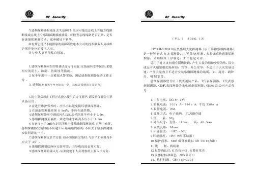
9020/9010气体检测报警控制单元中文安装使用说明书中美合资无锡梅思安安全设备有限公司WUXI MSA SAFETY EQUIPMENT CO. LTD.在安装或使用、维护本产品前,必须仔细阅读本说明书,并严格按照说明书所规定的范围进行操作。
目录一、概述 (4)二、技术规格 (4)三、面板功能 (4)四、接线端子及系统连接示意图 (5)五、安装 (5)1.简述 (5)2.9010/9020仪表 (6)3.常用探测器的安装 (6)4.传输电缆(连接500S点型可燃性气体探测器) (6)六、检查 (7)七、基本操作 (7)1.功能代码简介 (7)1.1 功能代码之意义 (7)1.2 功能代码1,3,5,123和223的进入方法:.. 71.3 功能代码2,4,7,52,53等的进入方法: (7)2.常用的标定校准操作 (8)2.1 标定校准包括4个基本步骤 (8)2.2 标定校准过程如下 (8)3.功能代码简述 (9)3.1 功能代码1 检测通道的标定校准操作 (9)3.2 功能代码2 特殊工作条件的设定 (9)3.3 功能代码3 模拟检查操作 (9)3.4 功能代码4 参数设定操作 (10)3.5 功能代码5 事件保存和打印功能 (11)3.6 功能代码7 外围地址的设定 (12)3.7 功能代码52 初始化操作 (12)3.8 功能代码53 默认设置 (12)3.9 功能代码123 (13)4.预置口令的使用 (13)八、常见故障及错误信息 (13)九、订货须知 (14)十、附图 (15)一、概述本产品为意大利MSA公司原装进口仪表,功能完善,性能可靠。
通过配置各型气体探测器,可以提供可靠的气体监测和报警,为各种工业领域提供安全服务。
仪表有两个型号:9010和9020控制器。
其中9010为单通道仪表,可配接一只气体探测器,9020为双通道仪表,两个通道互相独立,可同时配接两只相同或不同的气体探测器。
Model 9010/9020 LCD Control Unit[The Sophisticated Hazardous Gas Warning System ]two independent sensors [dual channel] per con t rol module offering con s iderable cost saving while main-taining high reliability and performance.Modular design combined with dual channel capa -bi l ity allows for high density packaging in a single 19Љrack [up to 20 points].A high level of reliability is possible as each control module is fitted with an independent AC/DC power supply transformer and logic circuit with software validated according to ATEX Directive 94/9/EC.MSA’s 9010/9020LCD control units are designed to offer maximum flexibility to work in conjunction with a wide variety of remote sensors to provide reliable gas detection in a wide range of industries and applications.Advanced design using SMD and mostly RoHS Direc-tive compliant components throughout and innova-tive features put the 9010/9020 LCD control units a step ahead of any conventional gas warning system.The 9010 LCD operates with one independent sensor[single channel] while the 9020 LCD operates withFour channel IP65 wall mount with common alarm. Marine Directive MED 96/98/EC approved for all demanding applications. Please ask for specific leaflet 07-517.2.[Features]■ATEX 94/9/EC compatible where applicable■Failure status for low AC/DC power■Over range EEEE latching■Series connected opto-isolators provide failure status■Redundant dual contact failure relay[selectable latch-ing/non-latching function]■Alarm threshold inhibit■Choice of measuring units – LEL-LELm-PPM-%Vol-g/m3or blank■Operates with a complete range of gas sensors and transmitters including semiconductor sensors, conven-tional smoke and temperature sensors, manual call points, thermo-resistive cable■4–20 mA current loop accept [one person]■Full internal diagnostics■User-friendly configurable operation■Firmware can be easily loaded via laptop■Versatile system functions with logic levels■Adjustments via membrane keypads■Up to 20 channels per rack■Individual terminal blocks per module[LCD Display]The 9010/9020 LCD features large 4-digit 7-segment back lit Liquid Crystal Display and high brightness LED’s to provide ease of reading and alarm visu a lisation.The display provides information on the gas concentration, alarm status, measurement units, flags indicating status and settings such as cali b ration interval, time-out function, alarm ON delay and alarm inhibit.[TWA-STEL]When operating in connection with toxic sensors,the 9010/9020LCD can be set to alarm when relevant STEL and TWA values are exceeded.[Sensor Wiring]According to the specific applica t ion, the remote sensors can be connected by means of 2, 3 or 4 wire cabling.3[Rack Dimensions ]For installation inclassified Zones 1 and 2.N o 12 HOLES 3/4ЉUNI 6125395 m m385 mmhousing [ATEX]with up to 4 modules [8 points-9020 LCD].[Benefits ]■Meets ATEX Directive 94/9/EC require m ents■A multi-purpose version which accepts both bridge [mV] and active [4–20 mA] input signals■A cost-effective version operating on a 4–20 mA input signal is also available■Satisfies a variety of gas monitor i ng applications/industries ■Inherent reliability minimises spurious alarms and unexpect -ed “down-time”■No tools required for adjustments [operation by Access Code]■High density monitoringEach control module has an independent LCD display specific to each channel and three keys for configuration, calibration and routine operation. Specific access codes to the various features prevent accidental or undesired tampering.Error and failure messages on the display warn of any opera-tional anomalies.Each channel may be equipped with an optional card to provide opto-isolated outputs for the three alarm thresholds:C [Caution] W [Warning] A [Alarm]. The card may either be with common emitter or common collector output.Each module has two [SPDT] relays with change-over contacts for remote repeat of Warning [W] and Alarm [A] conditions [common to both channels in the 9020 LCD version].The analogue output signal for each channel can be linearised.An RS-485 interactive serial interface is available [double on request]. A customised ModBUS RTU protocol can be used for serial bus data transmission such as system configuration, gas concentration, alarm and failure events, alarm inhibit and reset.In addition to handling the sensor input signal [by current or voltage] the 9010/9020 LCD can also power the remote sensors [by constant current or voltage] enhancing the versatility of the system.The 9010/9020 LCD control units can be configured to meet the stringent requirements of the ATEX Directive 94/9/EC for com b ustible gas monitoring or to meet any other applications in gas detection including process control, such as suppressed Zero read i ng and reverse full scale range and output signal.[Type Approvals ]The 9010/9020 LCD control units are certified to meet the performance requirements of the following type approvals:Europe:EN 61779-1, EN 61779-4, EN 50271, EN 50104, EN 50402 [INERIS 00ATEX0028X], SIL 2 [pending],SBG Certificate No. 213.010 SOLAS 74/88[ MED 96/98/EC]RINA Certificate No. ELE 04 CS 176101,China:CCCF GB 16808-97 [pending]USA:MET Laboratories, Inc. Listing no. E112409,FM approval [pending]Russia:Pattern Approval Certificate of Measuring Instruments DE.C.31.001A No. 22292, GOST R ROSS DE.GB05.V02463Ukraine:Pattern Approval Certificate of Measuring Instruments No. UA-MI/1-1921-2006Protections■AC/DC automatic switching in case of mains failure by means of electronic switch■Accidental tampering by specific Access Codes and Password ■Software self-diagnosis by watch-dog and check-sumA/D Converter ■For controls16bit ± 1 @ 25°C with 4 multiplexed inlets ■For analogue signal 16 bit ± 1 @ 25°C with 2 multiplexed inlets Front panel size 3 U x 8 T. E.Weight720 g Electrical installation category IIATEX designationII [2] G [1] G certificate INERIS 00 ATEX 00 28X II 2GD EEx d IIC T5 IP 65 EC-typeCertificate INERIS 01 ATEX 0057 Ex-proof housing ApprovalsEMC 89/336/EEC-EN 50270TEST REPORT 78550 EMC NEMKO LOW VOLTAGE 73/23/EECTEST REPORT 78550 SAF NEMKO VIBRATIONS [9020-4 LCD only] NEMKO IND 2172-1/03[Technical Data ]Power supply115/230 VAC ± 15% 50/60 Hz 24 VDC + 15% – 20%Power consumption [no load]9010 LCD 9020 LCD ■AC supply 24VA transformer 13VA 15VA ■DC supply 24 VDC nominal 3 W 4W Sensor supply ■Constant current 5–500 mA 5–500 mA ■Constant voltage 3–24 VDC 3–24 VDCSensor connection modes 2-3-4 wiresConnection terminals for wires up to 2.5 mm 2Input signals10–200 mV/4–20 mAOutput signals can be linearised ■Analogue [normal]0–20/4–20 mA [selectable] floating ■Analogue [fault]0/2/4/20 mA/frozen [selectable]Serial interface RS-485Alarm levels 3C [Caution] W [Warning] A [Alarm]Alarm remote repeat■Via relay contacts [SPDT]5A @ 24 VDC/250 VAC*■Via opto-isolators [common collector or common emitter]30 mA @ 24 VDC max.**resistive loadFault and below zero drift alarm ■Via relayscommon to both channels on 9020 LCD and one channel on 9010 LCD ■Via opto-isolatorsindividual for each channel[optional card either common collector or emitter]Alarm handling ■Reset latching/non-latching ■ON delay0–9999 sec adjustable ■Automatic inhibit by specific Access Code ■Manual inhibitby specific Access Code Electronic speed of response <0.5 sec for 100% f.s.Span and Zero drift < ± 0.5% f.s. ± 1 digit/month Repeatability± 1% f.s. ± 1 digit Operating temperature –10° C to +50°C Storage temperature –20° C to +75° C Humidity 90% R.H. non-condensing Vibrations unaffected within 10 to 55 Hz, 0.15 mm bandwidthLCD display back lit Liquid Crystal Display/ 4 digit 7 segments Optical alarmshigh brightness LED’s Warm-up and self-diagnosis time 60 sec/channel Time-out setting2–6 minDefault and configuration datastored in EEPROM/MP[Ordering Information ]10093583 9010 LCD 24 VA mV & mA 100935859010 LCD 24 VA 4–20 mA 100935829020 LCD 24 VA mV & mA 100935849020 LCD 24 VA 4–20 mA 100936629010 LCD wall mount IP 54 100936639020 LCD wall mount IP 54100936649020-4 LCD wall mount IP 65 10094046Opto-isolator card common collector 10094047Opto-isolator card common emitter 100935869010 main pcb with header 100935889020 main pcb with header10029374 Blank panel 10029329 Rack 19Љ/2 slots 10029370 Rack 19Љ/5 slots 10029328 Rack 19Љ/10 slots 10035782 Rack, mounting plate & ABS enclosure 5-way 10035783Rack, mounting plate & ABS enclosure 2-way Ex-proof ATEX version system is available on requestSouthern EuropeMSA Italiana S.p.A., Rozzano Phone +39 [02] 89 217-1E-Mail *************************International Sales MSA EUROPE, BerlinPhone +49[30]6886-555E-Mail **********************Great BritainMSA [Britain] Limited, Coatbridge Phone +44 [12 36] 42 49 66E-Mail ******************.ukMSA EUROPE Regional Head Offices & Great Britain [ ]Northern EuropeMSA Nederland B.V., Hoorn Phone +31 [229] 25 03 03E-Mail **************Central EuropeMSA AUER GmbH, Berlin Phone +49[30]6886-2490E-Mail ************Eastern EuropeMSA Poland Sp.z o.o.,Warsaw Phone +48[22]711-5033E-Mail ******************ID 07-516.2 GB/04/NL/09.08/HA。
9020/9010气体检测报警控制单元中文安装使用说明书梅思安(中国)安全设备有限公司MSA (CHINA) SAFETY EQUIPMENT CO. LTD.在安装或使用、维护本产品前,必须仔细阅读本说明书,并严格按照说明书所规定的范围进行操作。
目录一、概述 ........................................................ 3.二、技术规格 .................................................... 3.三、面板功能 .................................................... 3.四、接线端子及系统连接示意图 (4)五、安装 ....................................................... 4..1. 简述 (4)2. 9010/9020 仪表 (5)3. 常用探测器的安装 (5)4. 传输电缆(连接500S点型可燃性气体探测器) (5)六、检查 ........................................................ 6.七、基本操作 .................................................... 6.1. 功能代码简介 (6)1.1 功能代码之意义 (6)1.2 功能代码1, 3, 5, 123和223的进入方法:..61.3 功能代码2, 4, 7, 52, 53等的进入方法: (6)2. 常用的标定校准操作 (7)2.1 标定校准包括4个基本步骤 (7)2.2 标定校准过程如下 (7)3. 功能代码简述 (8)3.1 功能代码1检测通道的标定校准操作 (8)3.2 功能代码2特殊工作条件的设定 (8)3.3 功能代码3 模拟检查操作 (8)3.4 功能代码4 参数设定操作 (9)3.5 功能代码5事件保存和打印功能 (10)3.6 功能代码7外围地址的设定 (10)3.7 功能代码52初始化操作 (10)3.8 功能代码53 默认设置 (11)3.9 功能代码123 (12)4. 预置口令的使用 (12)八、常见故障及错误信息 (12)九、订货须知 ................................................... 1.3十、附图 (13)概述本产品为意大利MSA公司原装进口仪表,功能完善,性能可靠。