开博尔K760i说明
- 格式:pdf
- 大小:18.80 MB
- 文档页数:16

开博尔Q7-4K版评测硬盘播放器完美演绎4K蓝光概述:开博尔Q7-4K版怎么样?小编从开博尔Q7-4K版的外观造型、UI界面、硬件跑分、视频格式支持、本地播放、亮点功能,这些方面进行详细的试用介绍!之前小编对发烧级4K蓝光播放器开博尔Q9次世代做了详细评测,今天为大家带来的同样是一款发烧友期待的4K蓝光播放器——开博尔Q7-4K版!开博尔Q7-4K版强势来袭!支持最新的4K蓝光标准,让家里的客厅瞬间变为您的专属私人影院。
全新KIUI9.0轻量化系统,更流畅简洁。
同时搭载64位八核至强CPU,硬件发烧!更有内置硬盘仓,支持6T 容量硬盘。
小编对开博尔Q7-4K版进行全面评测,让用户对开博尔Q7-4K版有更深入的了解。
4K蓝光播放器开博尔Q7-4K版怎么样?小编从开博尔Q7-4K版的外观造型、UI界面、硬件跑分、视频格式支持、本地播放、亮点功能,这些方面进行了评测,通过试用告诉你开博尔Q7-4K版好不好!一、外观造型开博尔Q7-4K版外包装手提袋采用黑色底色,正面印有4K时代、影视先锋,全球第一款4K蓝光播放器,品牌LOGO字样。
侧面分别是售后服务热线、官方网站、公司简介等信息,尽显正规。
整体高端大气,手提式包装袋方便携带,送人也“倍儿有面子”!开博尔Q7-4K版外包装手提袋开博尔Q7-4K版外包装手提袋开博尔Q7-4K版包装盒底色为黑色,上面黑色的字体介绍盒子的亮点特色,时尚潮流,透漏出一种低调却很有内涵的气质。
左上角品牌LOGO,右下角产品型号等信息格外醒目。
侧面中间的彩色图案给盒子增添了几分“鲜活气息”。
包装背面标有产品名称、产品型号、产品介绍、亮点功能等信息。
开博尔Q7-4K版包装盒正面开博尔Q7-4K版包装盒侧面开博尔Q7-4K版包装盒侧面开博尔Q7-4K版包装盒侧面开博尔Q7-4K版包装盒侧面开博尔Q7-4K版包装盒底面拆去开博尔Q7-4K版外包装,取出包装内的所有产品,来一张全家福!开博尔Q7-4K 版盒子、遥控器、电源线、HDMI线、说明书。
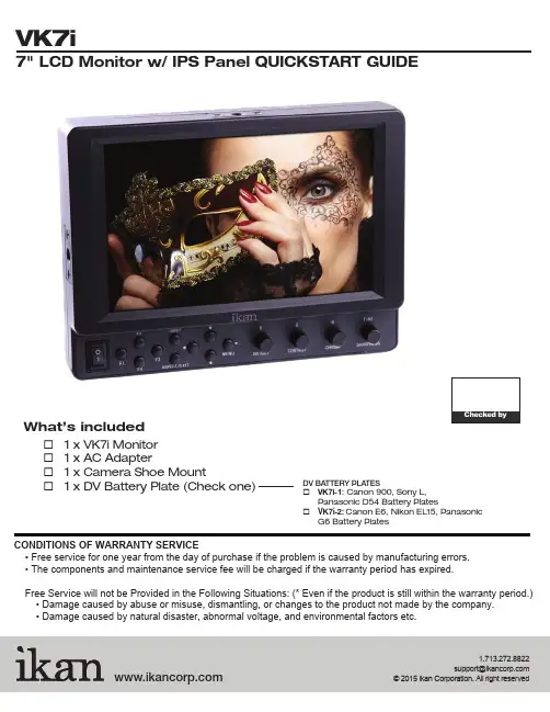
CONDITIONS OF WARRANTY SERVICE• Free service for one year from the day of purchase if the problem is caused by manufacturing errors. • The components and maintenance service fee will be charged if the warranty period has expired.Free Service will not be Provided in the Following Situations: (* Even if the product is still within the warranty period.) • Damage caused by abuse or misuse, dismantling, or changes to the product not made by the company. • Damage caused by natural disaster, abnormal voltage, and environmental factors etc.1.713.272.8822********************What’s included☐ 1 x VK7i Monitor ☐ 1 x AC Adapter☐ 1 x Camera Shoe Mount☐ 1 x DV Battery Plate (Check one)DV BATTERY PLATES☐ VK7i-1: Canon 900, Sony L, Panasonic D54 Battery Plates☐ V K7i-2: Canon E6, Nikon EL15, PanasonicG6 Battery PlatesVK7i1281211109131415Power SwitchPower ON / OFFPower Indicator Light When the power is ON, the LED green lights up Button T oggle left in MENU setting modeand ButtonsT oggle up and down in MENU setting mode / MENU ButtonT oggle right in MENU setting modeIn MENU, push button to select menu setting BRIGHT/R KnobAdjust brightness 0 - 100 (50)Adjust red channel CONTRAST/G KnobAdjust contrast 0 - 100 (50)Adjust green channel CHROMA/B KnobAdjust chroma 0 - 100 (50)Adjust blue channelTINT/SHARPNESS KnobAdjust tint 0 - 100 (50)Adjust sharpness 0 - 100 (10)TALL Y Indicator Lights1TALL Y Indicator LightsVIDEO terminal (BNC)IN : Composite signal input terminal OUT : Input signal through-out terminal YPbPr terminal (BNC)IN : Component signal input terminal OUT : : Input signal through-out terminal HDMI terminalIN : HDMI input terminalOUT : : Input signal through-out terminal DC 12V-24V power terminal XLR DC Connection TALL Y Input Connector RJ45 Connection DC 7-24V power terminal Standard DC ConnectionVESA 100mm Mount HolesThreaded for M3x.07 screws. Use to attach pro battery plate adapter or for mounting third party vesa mounts. USB terminalFor factory service use only¼-20 Threaded insert (on three sides of monitor) Mounting MonitorDV Battery Plate SlotMounting ikan DV battery plate234568791110++TALLYThe MANUAL function allows you to change the values of Red, Green, and Blue (RGB).This function recalls user de ned values settings .The user setting will remain in memory inde nitely and can be erased by using the reset option in the main menu.The DSLR Scaling function will allow users to extend their DSLR camera’s HDMI video output any option of four – Normal, 3:2, 16:9 or Full Screen – convenience made simple.This function displays the blanking portion of the incoming signal.The LCD panel in this display has a native display of 1280 x 800 pixels. A signal of any other resolution is scaled to t this native resolution. There may be time when it is desired to view the incoming signal without scaling. Enabling Pixel to Pixel mode turns off the scaling and displays a 1024x600 pixel window of the original image. Each pixel of the panel displays one pixel of the original image. The user may use the arrow buttons(buttons 3-6) on the monitor face to move the window left, right, up and down to see thedesired portion of the image. The VK7i is equipped with Monochrome Peaking features which highlight the desired focus area in a bright, red outline. The operator adjusts the focus control until the red indicator outlines on the desired area are razor sharp, indicating optimal focus. For the best results, be sure the subject is properly exposed.The False Color feature utilizes a full spectrum of assigned color indicators, ensuring awless shot exposure. As the camera Iris is adjusted, the subject of the image will change color based on speci c brightness values indicating optimal exposure. See included chart for color assignments.As an additional tool associated with the VK7i’s False Color feature, ikan’s exclusive Adjustable Under Exposure and Over Exposed Waning feature gives the operator full control of the VK7i False Color brightness values. By setting the preferred IRE exposure limits, the operator is warned when the image exposure is exceeding or falling under the preset IRE limit, providing customizable, full image exposure control.The VK7i offers adjustable upper Clip Guide levels to accurately display overexposed images in any shooting condition. The operator simply assigns the upper IRE to their preference and any exposure over the set IRE limit will ash in a vivid purple, indicatingonly the over exposed area.This function displays a side by side comparison of the incoming video signal. Pushing the F1/2 button one time will enter the mode. Each time the F1/2 button is pushed it will freeze the current frame on the right hand side of the display while the left continues to display the live signal. Pressing the exit button will exit the window mode. Use Window 1 for 16:9 signals and Window 2 for 4:3 signals. Display a crosshair on the center of screen.Brightness 0-100Contrast 0-100Chroma 0-100Sharpness 0-100Tint 0-100Color T emp. 5600 K6500 K9300 K MANUAL OSD Language English Chinese OSD Duration5-60 secondLuma Under Warn Luma Over WarnFuction 1 Window 1Window 2 HV DelayGuidesPeakingFalse Color Clip Guide Underscan DSLR Scaling Check Field Pixel Fuction 2 Window 1 Window 2 HV DelayGuidesPeakingFalse Color Clip Guide UnderscanDSLR Scaling Check Field Pixel Menu SetupUser 1-5System ResetCONFIGURATION OF SETTING MENUSCrosshairCrosshairFEATURES• 1280 x 800 resolution• Looping HDMI, Component, and Composite I/O• False Color - Adjustable Under Luminance & Over Luminance Warning• Clip Guide - Adjustable Threshold• Peaking Red outline• Under scan• Color T emperature Presets (9300K/6500K/5600K)• Guides (4: 3 & 16:9 Framing Safe Area)• Check Field (Blue gun, red, green, mono)• Side-By-Side Freeze Frame• H/V Delay• Aspect Ratio (FULL / 16: 9 / 4: 3)• 5 user-de ned group• RGB Adjust• Resolution support - 480i/p ; 576i/p ; 720p24hz 25hz 30hz 50hz 60hz 24hzsf 25hzsf; 1080i/p 24hz 25hz 30hz 50hz 60hz 24hzsf 25hzsf • T ally system• DSLR scaling• Moveable pixel-to-pixelSPECIFICATIONSScreen Size: Diagonal 7" LCDResolution: 1280 x 800LCD Brightness: 400 NITViewing angles: 170(H) 170 (V)Operating Volts: DC 7 to 24VPower Consumption: 7 WattVideo Inputs: HDMI, Component, CompositeVideo Outputs: HDMI, Component, CompositeDimension: 5.6"H x 7.3"W x 1.6"DWeight: 18 lbs。
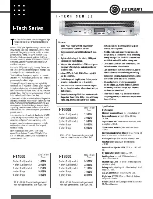
The Crown ® I-Tech Series offers amazing power, light weight and ease of use for touring sound applica-tions.Onboard DSP (Digital Signal Processing) provides a widearray of signal processing (compression, limiting, fi lters, and so on). This greatly reduces the need for rack com-ponents and rack wiring. The DSP features 24-bit, 96 kHz A/D and D/A converters. All models in the I-Tech Series are compatible with the IQ ® Network and TCP/IQ™ networking. CobraNet™ input available in optional CN models, coming soon.Pushbutton DSP presets simplify the setup. Custom pre-sets can be downloaded into the amplifi er, making it easy to confi gure for various loudspeaker arrays.The Global Power Supply works anywhere in the world, and offers PFC (Power Factor Correction). It is a switching power supply for reduced weight.I-Tech amplifi ers provide amazing power: up to 8 kWcontinuous and 10 kW peak in a 2U rack space. They have the highest output voltage in the industry (200V peak), which provides clean transient peaks. The 3rd-generationpatented Class I (BCA ®) circuitry couples power effi ciently to the load and provides low current drain.A front-panel control screen shows advanced diagnostics and status information. All controls are set from the front panel. A comprehensive array of indicators provide accu-rate diagnostics: Power, Data, Bridge, along with Ready, Signal, Clip, Thermal and Fault for each channel. An AC mains indicator in the power switch glows green when AC power is present.Input connectors include analog XLR and digital AES/EBU. Analog and digital thru connectors are provided. Outputconnectors are Speakon ®and 5-way binding posts.Advanced protection includes a management controller and two discrete thermal zones with variable-speed, forced-air cooling.For more details about the Crown I-Tech Series,contact Crown Customer Service at 800-342-6939 or 574-294-8200. Also, visit the Crown Audio website at .Specifi cations PerformanceMinimum Guaranteed Power: See power charts at left.Frequency Response (at 1 watt, 20 Hz - 20 kHz): ±0.25dB.Signal to Noise Ratio below rated full-bandwidth power, A-weighted: > 105 dB.Total Harmonic Distortion (THD) at full rated power: < 0.35%.Intermodulation Distortion (IMD) 60 Hz and 7 kHz at 4:1, from full rated output to –35 dB: < 0.35%.Damping Factor (20 Hz to 100 Hz at 8 ohms): > 5000.Crosstalk (below rated power, 20 Hz to 1 kHz): > 80 dB.Common Mode Rejection (CMR) (20 Hz to 1 kHz): > 50 dB.DC Output Offset (shorted input): < ± 3 mV.Input Impedance (nominal): 20 kilohms balanced, 10 kilohms unbalanced.Maximum Input Level: +15 dBu or +22 dBu, depending on input sensitivity.Latency (analog, digital inputs): 1.13 mS analog, 2.36 mS digital (44.1 kHz).A/D, D/A Converters : 24-bit 96 kHz Cirrus Logic.Digital Input: AES/EBU, 16-24 bit, 32-48 kHz. Onboard sample-rate converter.Network: Onboard TCP/IQ, compatible with standard 100 Mb Ethernet hardware.Features• Global Power Supply with PFC (Power Factor Correction) works anywhere in the world.• High power density, up to 8000 watts in a 2U chas-sis.• Highest output voltage in the industry (200V peak) provides clean transient peaks.• 3rd-generation patented Class I (BCA) circuitry cou-ples power effi ciently to the load and provides low AC current drain.• Onboard DSP with 24-bit, 96 kHz Cirrus Logic A/D and D/A converters.• Pushbutton presets simplify setup. Custom presets for various loudspeakers can be downloaded.• Front-panel control screen with advanced diagnos-tics and status information. All controls are set from the front panel.• Comprehensive array of indicators provide accurate diagnostics: Power, Data, Bridge, along with Ready, Signal, Clip, Thermal and Fault for each channel.• AC mains indicator in power switch glows green when AC power is present.• AES/EBU digital audio input. Ethernet connector accepts an RJ-45 connector for TCP/IQ networking. Analog and digital thru connectors. CobraNet input available in optional CN models, coming soon. • Labels on rear panel are color coded to group simi-lar functions under common colors.• Light weight due to aluminum construction, special internal construction and switching power supply.• Management controller, two discrete thermal zones with variable-speed fans, forced-air cooling.• Advanced protection circuitry guards against: shorted outputs, DC, mismatched loads, general overheating, under/over voltage, high-frequency overloads and internal faults.• Three-Year, No-Fault, Fully Transferable Warranty completely protects your investment and guarantees its specifi cations.12I-T40002-ohm Dual (per ch.) 4-ohm Dual (per ch.) 8-ohm Dual (per ch.) 4-ohm Bridge 8-ohm Bridge20 Hz - 20 kHzPower20 Hz - 20 kHz Power refers to guaranteed minimum power in watts with 0.35% THD.4,000W 3,600W1,800W 2,000W 1,250W I-T60002-ohm Dual (per ch.) 4-ohm Dual (per ch.) 8-ohm Dual (per ch.) 4-ohm Bridge 8-ohm Bridge20 Hz - 20 kHzPower20 Hz - 20 kHz Power refers to guaranteed minimum power in watts with 0.35% THD.6,000W5,000W 2,500W 3,000W 1,500WI-T80002-ohm Dual (per ch.) 4-ohm Dual (per ch.) 8-ohm Dual (per ch.) 4-ohm Bridge 8-ohm Bridge20 Hz - 20 kHzPower20 Hz - 20 kHz Power refers to guaranteed minimum power in watts with 0.35% THD.8,000W7,000W 3,500W4,000W 2,100WCrown International P .O. Box 1000Elkhart, IN 46515-1000 TEL: 574-294-8200FAX: 574-294-8FAX 4/04 137251-1FDSP: 24-bit conversion with 32-bit, fl oating-point DSP processing. Has 64 assignable fi lters with 9 different fi lter types. Includes all-pass fi lters, over 2 seconds of delay available per channel, and dual uncorrelated-noise and sine-wave generators.Load Supervision: Monitors the average impedance on the output of the amplifi er. If the impedance falls outside the specifi ed high/low limits, this function alerts the user via the front panel display, and via the IQwic™ software when amp is on an IQ Network.Error Reporting: Reports clip errors, thermal errors, fault conditions and load monitoring errors for each channel via the front panel display and via IQwic software when amp is on an IQ Network.Attenuators: Speed sensitive, continuously variable rotary encoder, 0.5 dB steps, range 0 to –90 dB.Load Impedance (Note: Safe with all types of loads):Stereo: 1/2/4/8/16 ohms.Bridge Mono: 2/4/8 ohms.Input Sensitivity (referenced to 8 ohm rated output): Adjustable in 0.1V steps from 1.4V to 7.75V.Voltage Gain (referenced to 8 ohm rated output): I-T4000: 37.1 dB to 22.2 dB I-T6000: 37.9 dB to 23.0 dB I-T8000: 39.3 dB to 24.5 dBRequired AC Mains: Universal AC input, 100-240VAC, 50/60 Hz (±15%). Maximum AC mains voltage 277VAC.AC Line Connector: Five cordsets supplied with amplifi er (USA, UK, European, Australia, India).Front Panel Controls and IndicatorsBridge Mode Indicator: Yellow LED illuminates when the amplifi er is set to Bridge-Mono mode. Ready Indicator: Green LED, one per channel, illuminates when the channel is initialized and ready to produce audio output. Indicator is off when the amplifi er is in standby mode via the IQ system.Signal Indicators: Three green LEDs per channel indicate the amplifi er’s input and output signal levels.Signal: input signal is above –40 dBu.–20 dB: amplifi er output is 20 dB below clipping.–10 dB: amplifi er output is 10 dB below clipping.Clip Indicator: Red LED, one per channel, illuminates when the channel’s output signal reaches the onset of audible clipping. The Clip Indicator also will illuminate during Thermal Level Control (TLC) limiting.Thermal Indicator: Red LED, one per channel, illuminateswhen the channel has shut down, or is very near shutting down, due to thermal stress or overload.Fault Indicator: Red LED, one per channel, fl ashes when the amplifi er output channel has stopped operating.Data Indicator: Yellow LED indicates IQ Network data activity. Data indicator fl ashes only when the amplifi er is polled for data, or is polled to see whether it is online Power Indicator: Blue LED indicates amplifi er has been turned on and AC power is available. The LED will fl ash when the AC line voltage is 15% above or below the nominal rated value.AC Mains Present Indicator: Green indicator built into power switch indicates AC power is present at the power cord and the amplifi er circuit breaker is in the “on” posi-tion.LCD Control Screen and Controls: These let the user adjust the amplifi er’s attenuation and muting, confi gure the amp, set up and view error monitoring (such as tem-perature and load supervision), and recall DSP presets. The presets allow the user to quickly reconfi gure the amp for various applications.LCD Control Screen: Integrated LCD with white LED back-light, controls amplifi er setup and operation.Normal mode: Attenuation in 0.5 dB steps, Mute/Unmute, Front Panel Lockout.Basic Menu: LCD Contrast, CH1 Sensitivity, CH2 Sensitiv-ity, Speaker Preset, Dual/Bridge mode, Input Y.Advanced Features Menu: Attenuator Limits, Attenuator Link, Clip Limiter, Peak Voltage Limiter, Average Power Limiter, Pink Noise Generator, AES/EBU Input Trim, Input Source, Maximum Analog Input, Amplifi er Label Edit, CH1 Label Edit, CH2 Label Edit.Menu/Exit Button: “Menu” enters the main menu. “Exit” gets out of the Menu.Next Button: Selects the next item in the Menu.Prev Button: Selects the previous item in the Menu.Level Controls (Encoders): Speed-sensitive rotary encod-ers, 0.5 dB steps, range 0 to –90 dB. These two knobs affect the Channel-1 and Channel-2 output levels. They also select Menu items and adjust parameter values that are displayed on the LCD Control Screen.Power Switch: Push-on/push-off switch with built-in green AC mains present indicator.Back Panel Controls, Indicators and ConnectorsPower Cord Connector: Standard 20 amp IEC inlet. Volt-age range is indicated above IEC inlet.Reset Switch/Circuit Breaker: If the current draw of the amplifi er exceeds safe limits, this breaker automatically disconnects the power supply from the AC mains. The switch resets the circuit breaker.Output Connectors: Two high-current, 50A Neutrik ®Speakon ®NL4MLP (mates with NL4FC), one per channel. Two pairs of high-current, 60A color-coded 5-way binding posts (for banana plugs, spade lugs or bare wire). Two male XLR passive analog loop through. XLR active/re-clocked AES/EBU digital loop through.Analog Input Connectors: A 3-pin female XLR connector for each channel.Digital Input Connector: A 3-pin female XLR connector that accepts a digital signal in the AES/EBU format.Ground Lift Switch: Isolates input ground from AC ground.Network Connector: This Ethernet connector accepts an RJ-45 connector for TCP/IQ networking. Built into the connector is a yellow LINK ACT indicator that shows network activity, and a green 100Mb indicator that shows a 100Mb network connection.Data Indicator: Yellow LED indicates IQ Network data activity. Data indicator fl ashes only when the amplifi er is polled for data, or is polled to see whether it is online.Preset Indicator: Yellow LED fl ashes to signal the number of the current preset if active.ConstructionCooling: Dual-zone, microprocessor controlled, continu-ously variable speed fans, front-to-back airfl ow.Front Panel: Cast aluminum with integrated handles.Dimensions: 19 in. (48.3 cm) W x 3.5 in. (8.9 cm) H x 16.2 in. (41.1 cm) D.Weight: 28 lbs (12.7 kg) net, 36 lbs (16.3 kg) shipping.Included Accessories: Rear rack ears with integral EZ-Rack Pin, rack screws, operation manual, power cords, foam air fi lter.© 2004 Crown Audio ®Inc.Specifi cations subject to change without prior notice. Latest information available at .Crown, Crown Audio, IQ, and BCA are registered trademarks of Crown International. TCP/IQ and IQwic are trademarks of Crown International. Other trademarks are the propertyof their respective owners. Printed in U.S.A.Crown’s Three-Year, No-Fault, Fully Transferable WarrantyCrown offers a Three-Year, No-Fault, Fully Transferable Warranty for every new Crown amplifi er—an unsurpassedindustry standard. With this unprecedented No-Fault protection, your new Crown amplifi er is warranted to meet or exceed original specifi cations for the fi rst three years of ownership. During this time, if your amplifi er fails, or does not perform to original specifi cations, it will be repaired or replaced at our expense. About the only things not covered by this warranty are those losses normally covered by insurance and those caused by intentional abuse. And the coverage is transferable, should you sell your amplifi er.See your authorized Crown dealer for full warranty disclosure and details. For customers outside of the USA, please contact your authorized Crown distributor for warranty information or call 574-294-8200.。

概述EDI-760称重显示仪表是北京首昌大和公司在长期从事称重仪表研究的基础上,运用最新仪表设计技术而推出的新一代智能化称重仪表。
该仪表系统集成度高,电路布局合理;输入输出控制功能强;精度高,稳定性能好。
广泛用于电子汽车衡、轨道衡及各种电子台秤,并可配接大屏幕显示器及计算机进行使用,为企业实现计量管理现代化提供有效的保证。
主要特点如下:·完全数字定标,标定和编程设定完全通过键盘完成。
·高灵敏度0.2uV/分度,对应10mV输入可产生显示码50000。
·提供RS232/RS485异步串行通讯接口,可简单的与PC通讯·仪表提供一路4~20mA重量数据输出·功能数据存储在EEPROM中可永久保存。
·可选用本公司的通用扩展输出卡EV917/EV918/EV919/EV920,实现并行的BCD码或二进制重量数据输出和多个控制点输出功能及增加一路4~20mA模拟量输出,可简单的与PLC通讯。
目录第一部分规格第二部分安装说明2.1 必要的环境条件2.2 接线插座2.3 接地线2.4 传感器连接及针脚分配CN1第三部分功能介绍和操作说明3.1 按键功能说明3.2 状态标志符3.3 功能数据说明第四部分检定说明4.1 准备工作4.2 扣除初始固定荷重(即标零)4.3 计量通道增益调整(即标量程)第五部分错误信息的说明5.1 错误编码的定义5.2 错误信息的清除第六部分输入输出接口的说明6.1 传感器电缆连接插座CN1针脚分配6.2 串行数据传输连接插座CN26.3 控制点输入输出插座CN36.4 并行输出插座CN5(EV918板)6.5 输入输出特性6.6 模拟量输出CN4端子DC4~20mA特性第七部分外形尺寸图第一部分规格·型号EDI-760称重显示器·显示7段8位高亮绿色荧光显示屏·重量显示范围可达99999或999990·分度值1、2、5、10、20或50·零点调整范围相对标定零的满量程的±2%范围内·自动零点修正修正范围满量程的±2%·模拟输入:灵敏度0.2uV/分度满量程范围30mV·A/D特性:转换方式Δ-Σ模数转换转换速率50次/秒分辨率标准10mV输入,显示码50000供桥仪表内部提供DC10V供桥传感器连接最多可并联8只350Ω的传感器必要条件长距离传输需用六线制电缆·精度和稳定性:非线性优于F.S的0.005%量程温度系数优于±15PPM/℃零点温度系数优±0.2uV/℃·配置接口仪表标配RS232C、RS485串行接口和开关量点输入和输出接口;可选配并行输出扩展板EV917/918/919完成并行数据和状态点输出,也可选配EV920完成4~20mA重量输出。
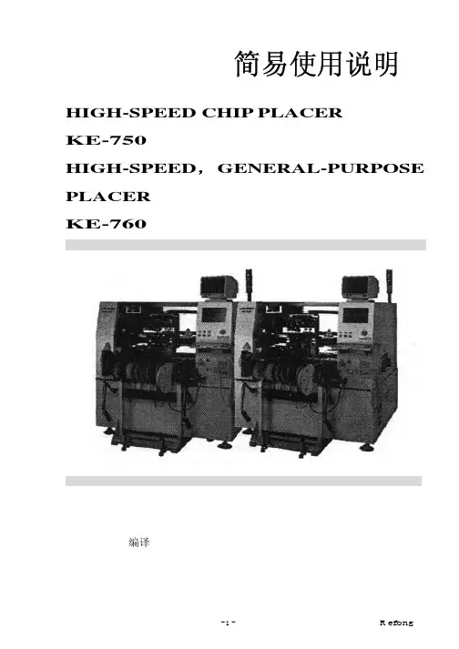
简易使用说明 HIGH-SPEED CHIP PLACERKE-750HIGH-SPEED,GENERAL-PURPOSE PLACERKE-760TSUI_R efong 编译 目录第一章机台简介1-1 机台构造简介 (4)1-2 规格 (4)1-3 雷射检测 (5)1-4 零件的型态 (7)1-5 英文缩写说明 (9)1-6 输送带简介 (10)1-7 FEEDER(送料器)简介 (11)1-8 ATC简介 (12)1-9 NOZZLE(吸嘴)简介 (13)1-10 键盘功能键 (14)1-11 HOD手持控制器 (15)1-12 机台上的其它按键 (16)1-13 IC CONVEYOR (16)第二章生产画面介绍2-1 画面 (17)2-2 选单 (19)2-3 暂停画面 (21)2-4 选单介绍(主选单及Data Input选单) (22)Input(资料输入) T Data3-1 基本资料 (24)3-2 PWB DTAT (25)3-3 PLACEMENT DATA(着装资料) (27)3-4 COMPONENT DATA(零件数据) (29)3-5 PICK DATA(料站资料) (35)3-6 VISION DATA(视觉资料) (37)机械设定4-1 选单说明 (40)4-2 1/Units of measure (40)4-3 2/Opt. Option (41)4-4 3/Machine setup (43)4-5 Maual Control (47)快速入门5-1 开机 (50)5-2 关机 (50)5-3 异常处理 (50)5-5 双挂料改为单挂料 (50)5-6 BOC Mark点制作 (51)5-7 换线 (52)5-8 换料 (52)5-9 零件检测 (52)5-10最优化 (53)如何写一程序6-1 基本观念 (54)6-2 写程序 (55)机台简介1-1. 机台构造简介 KE-750装置三组HEAD,可装着最大2Omm。

CVN B760I GAMING PRO V20 CVN B760I FROZEN WIFI V202022年11月第一版版权说明本手册版权属于七彩虹公司所有,未经本公司书面许可,任何人不得对此说明书和其中所包含的任何资料进⾏复制、修改、翻译或出版。
免责声明1.本手册上所有图片仅供参考,请以实物为准。
产品信息会依不同国家及地区而有所变动,我们诚挚的建议您与当地的经销商或零售商确认目前销售产品的规格。
2.产品颜⾊可能会因拍照⻆度而与实际产品有所差异。
我们会尽⼒提供正确与完整的数据到网⻚上,并保留随时更正、修改⻚面信息的权利,恕不另⾏通知。
3.为保证用⼾的安全及合法权益,请按照本使用手册操作。
如不遵照本手册规范操作,对此所造成的后果我们不承担任何形式的责任。
4.以上所有产品涉及的其它名称及商标,我们公司拥有最终解释权。
商标版权本手册使用的所有商标均属于该商标的持有者所有。
AMD,Athlon™,Athlon™XP,Thoroughbred™和Duron™是Advanced Micro Devices 的注册商标。
Intel®和Pentium®是Intel Corporation的注册商标。
PS/2和OS®2是International Business Machines Corporation的注册商标。
Windows®95/98/2000/NT/XP/Vista是Microsoft Corporation的注册商标。
Netware®是Novell,Inc的注册商标。
Award®是Phoenix Technologies Ltd的注册商标。
AMI®是American Megatrends Inc的注册商标。
Kensington和MicroSaver是Kensington Technology Group的注册商标。
PCMCIA和CardBus是Personal Computer Memory Card International Association的注册商标。

USER MANUALM7Table of Contents1.GENERAL INFORMATION (2)1.1W ARNINGS AND RECOMMENDATIONS (2)1.2F UNCTION AND F EATURE (2)1.3F RONT VIEW (2)1.4R EAR VIEW (2)1.5D IMENSIONAL DATA AND INSTALLATION HEIGHTS (3)1.6W ALL-MOUNTED INSTALLATION (4)2.SYSTEM APPLICATION (5)2.1V ILLA OR SINGLE-FAMILY CONTEXT (5)2.2A PARTMENT BLOCK OR MULTI-FAMILY CONTEXT (5)3.OPERATION DESCRIPTION (7)3.1M AIN P AGE (7)3.2S HORTCUT PAGE (7)3.3A DJUSTING PAGE (8)3.4BASIC OPERATIONS (8)3.5SETUP INSTRUCTIONS (11)3.6U PLOAD PICTURE AS WALLPAPER (20)3.7U PLOAD MUSIC AS RINGTONE (20)4.SPECIFICATIONS (20)1. General information1.1 Warnings and recommendationsIt is important to read this manual carefully before proceeding with the installation. The guarantee automatically expires for negligence, misuse, tampering by unauthorizedpersonnel.The Video internal unit must only be installed indoors; it must not be exposed to water drops orsplashes.1.2 Function and Feature⚫ 7” capacitive touch screen monitor ⚫ Based on Android system ⚫ IP over 2-wire non-polarity ⚫ 1024(RGB)x600 pix resolution ⚫ Picture in Picture function⚫ Indicator: Power, mute, message, WIFI ⚫ Picture and video save⚫ Support the secondary door bell and ringer extension ⚫ Support WIFI for cloud intercom⚫Flexible power way: support remote and local power1.3 Front view+-1234567891. 7” touch screen display (16: 9)2. SD card slot3. 24v DC input4. Reset button5. Indicate lights for power, mute, message, WIFI6. Increase the volume7. Volume indicate lights8. Reduce the volume1.4 Rear view123456781. Mic2. Loudspeaker3. Interface for 2nd door bell and extension ring4. Interface for additional power supply, non-polarity5. Interface for 2-wire IP interface, non-polarity6. Configurator J1: remove for additional power supply7. Configurator J2: Master/Slave, remove for Slave8. SD card slot1.5 Dimensional data and installation heightshttps:///1201207-power_icon.html+-HOME232mm133m m15mmGround160 ~ 165m m135 ~ 140m mRecommended height, unless otherwise required by the law1.6 Wall-mounted installation12345671 - Mark the location of the bracket holes2 - Drill3 – Install expandable screw4 - Fix the wall bracket5 - Connect the wires with the interface according to the wiring diagrams.6 – Insert the connector into the monitor, using index finger, middle finger, ring finger and littlefinger is easy to insert7 - Put the monitor on its wall bracket2.System Application2.1Villa or single-family contextMonitor 3 PowerDoor StationSmartPhone APP INTERNETMonitor 2Monitor 1In villa(single-family) systems all of the unit can be connected with the power.2.2Apartment block or multi-family contextHome 1DistributorDoor StationSmartPhoneAPPINTERNETHome 2Home 3PowerIn multi-family systems (apartment blocks), you need the distributor to connect all of the monitor and door station.The distributor can be connected with each other via CAT-5 cable.Distributor1PowerPowerDistributor NPowerDistributor 2CAT-53.Operation Description3.1Main PageThe Main Page is your starting point for using all the applications on your monitor.Touch anywhere of the screen on monitor in standby mode, the Main Page will appear as follows:Icon description:System status icons: from left to right-Connection-Mute-Wi-FiDoor Connection to the outdoor panel to show imageCamera Connection to the IP cameraRecord Pictures and video reviewIntercom Call to other monitors in the house (if any).Setting Enter setting menuScreen off Shut the screen. The screen will automatically switch off after 30” if no activity is done.. Sliding the main page to the left will show shortcut page.. Sliding the main page to the right will show adjusting brightness and volume page 3.2Shortcut pageIcon description:WIFI Deactivate / activate WIFI (master monitor only)Silence Activate / deactivate do not disturb modeLeaving Deactivate / activate leaving mode,when leaving mode is active, the silence and transfer function will be onTransfer Deactivate / activate call transfer functionwhen transfer function is activate, the call from door panel will be transfer to APP.3.3Adjusting pageIcon description:Speaker Volume Adjust the volume from door stationRing Volume Adjust the ring/video volumeBrightness Adjust the screen brightness3.4BASIC OPERATIONSEnter Door ListP ush “Door” button Push door panel you want to see Then the monitor page will be shown as follows:1 23 4 5 6 7 8Icon description:1.The additional IP camera window2.Button for adjusting video quality3.Take picture4.Take video5.Open the first door6.Open the second door7.Start to talk with visitor8.Return home pageNote: The name of door panels can be set by user, Door1, Door2, Door3 and Door4 in default.The instruction to set name can be found from ‘Setting-Door’ in the Setting.Enter Camera ListP ush “Camera” button Push camera you want to seeThen the monitor page will be shown as follows:12 3Icon description:1.Button for adjusting video quality2.Take picture3.Return home pageNote: The name of camera can be set by user, Camera1, Camera2, Camera3 and Camera4 in default.The instruction to set name can be found from ‘Setting-Camera’ in the Setting.Enter Intercom ListP ush “Intercom” button Push the monitor you want to dial Then the dialing page will be shown as follows:12Icon description:1.Adjust volume2.Cancel the callThe called page is as follows:123Icon description:1.Adjusting volume2.Answer the call3.Hung up3.5SETUP INSTRUCTIONSAll settings should enter the setting page by touching the icon ’Setting’ from main page:Setting-Door Panel1From door list page above, choose the door you want to set, it will show the following page:123456Icon description:1.Set door panel name2.Set auto record mode. (None, Photo, Video)3.Set door panel ring tone4.Set door lock open time. (1s,2s,3s,4s,5s,6s,7s,8s,9s)5.Select IP camera for picture in picture function. To activate this function, please add IPcamera first. See “Setting-Camera”6.Turn on/off fish eye lensCloud intercomPress cloud menu, the following page will be shown:1Use App to scan the QR code, and add it to device list.The App link for smartphone:Android APP IOS APPNote: Users should turn on [Leaving] mode or [Transfer] mode to enable cloud intercom function Setting-Memory12345Parameter description:1.The usage of the memorya)Red means the volume of images storedb)Green means the volume of videos storedc)Grey means the available volume2.The number of pictures record3.The number of videos record4.The video time when take video5.Format MemorySetting-WIFI12Parameter description:1.WIFI switcher2.Select a WIFI network to joinSetting-Motion Detection1234Setting description:1.Turn on/off motion detection2.Set the lock to open when motion happen3.Set the time schedule for motion detection function4.Take picture when motion happenSetting-Mute123Setting description:1.Deactivate / activate “manual” for mute functionW hen activate “Manual” for mute function, there will no ring when visitor call from door panel.2.Deactivate / activate “schedule” for mute function3.Set schedule mute periodW hen setting “Schedule” mute function, there will no ring in the setting time. Setting-Time&Date12345Setting description:1.Turn on/off synchronization time automatedly2.Set time zone3.Set Date4.Set Time5.Deactivate / activate 12-hour or 24-hour formatSetting-Language1Setting description:1.Set languageSetting-Wallpaper12Setting description:1.Push to choose a new picture as wall paper2.The existing wallpaperSetting-SetupTo set monitor address, add RFID card, add IP camera, and upgrade system, user needs input password in the following page:1Note: default password: 12345Setting-Room-Address1234Parameter description:1.Set room number, the value can be 01 ~ 322.Set room name3.Set extension room number, the value can be 1-44.Confirm and restart the deviceSetting-RFID Card1234Setting description:1.Add new RFID card2.Delete all RFID card3.The number of existing RFID card4.The lock to open when swiping RFID cardSetting- Add RFID Card1For example: If apartment 01 wants to add RFID card, the procedure:1.P ush “Setting” →“RFID card” →“Add card”,2.Swipe the card on door station one by one, then push the 01 call button to finish it3.Sound prompt: add card - Beep 1 time, add card success: Beep 2 timesNote: When swipe card on the door station, the limited time is 90SThe indoor monitor can talk with door station when adding RFID card.Setting- swipe short time to open lock1, long time to open lock21Description:Time for short time swipe:1sTime for long time swipe: 3sSetting-Camera123Icon description:1.Modify IP camera setting2.Delete IP camera3.Add new IP cameraWhen push icon1 and icon 3, the following page will be shown:12345Parameter description:1.Type: Choose the brand of IP camera2.IP address name: set the name for IP camera.3.IPC address: Set IP address of IP cameraNote: the suggestion IP address for IP camera: from 192.168.137.134 to192.168.137.254ername: Fill in username of IP camera5.Password: Fill in password of IP cameraSetting-System12345678Setting description:1.Show hardware version2.Show software version3.Show model name4.Show Room number5.Show IP address6.Push to upgrade system7.Push to restore setting8.Push to change [setting] passwordAfter pushing upgrade button, the following page will be shown:1Setting description:1.Upgrade via SD carda.Create a new folder named “u pgrade”Note: please use lowercase lettersb.Put the system software in itc.P ush “Setting” →“System” →”System upgrade” →”SD upgrade” to start3.6Upload picture as wallpaperYou can use your own picture as the system wallpaper, the operation procedure:1.Prepare a Micro-SD card2.C reate a new folder named “w allpaper”, and copy your picture in itNote: please use lowercase letters3.P ush “Setting” →“Wallpaper” →”Choose a new wallpaper” to set3.7Upload music as ringtoneYou can use your own music as the ring tone, the operation procedure:1.Prepare a Micro-SD card2.Create a new folder named “ringtones”, and copy your music in itNote: please use lowercase letters3.P ush “Setting” →“Door” →”Ringtone” to set4.SpecificationsCategory SpecificationInput power DC: 24v, 50Hz/60HzPower Consumption Max: 6W, standby: 3WTFT LCD 7-inch digital TFT LCDLCD resolution 1024(RGB) x 600Connection with door station Support four 2-wire door stations (Maximum)Connection with CCTV Support 16 IP camera input (Maximum) Connection with extension monitor Support 3 extension monitorsMemory capacity TF card: 1024 pictures, 128 videos Dimensions (mm) 232mm*133mm*15mmWeight(kg) 0.43kg。
硬盘U 盘
现在,您就可以添加相关需要共享的文件夹给播放机共享了。
点击“媒体库”,然后选择“添加到媒体库”。
以上设置完成后,启动播放机后,播放机会自动搜索局域网上的 UPNP媒体服务器(例如:安装了
“Windows Media Player 11"的电脑),并分别显示文件名称在相应的<电影><音乐><图片>列表中。
选
5、关闭Windows的防火墙。
6、诊断:点击 开始→运行→输入 \\本机IP地址 或\\本计算机名字弹出。
此时,应该出现共享的share名字。
点击该名字,应该能够进入访问下面的内容,否则samba共享配
置不正确,请检查防火墙设置或访问权限方面的问题。
开博尔高清播放机带您进入高清世界!产品服务手册重要安全说明●为了减少火灾、触电或产品损坏的危险,请勿让本机遭受雨淋、受潮或滴溅上液体,也不要将诸如花瓶等盛水之器物置于本机之上。
●为了确保良好的通风条件,请勿将本机安装或置于书柜、内藏式机柜或其它密闭的空间里。
勿让窗帘或任何其它物体堵塞通风孔,以免因机器过热而造成触电或火灾危险。
●切勿将诸如点燃的蜡烛灯明火火源置于本机之上。
●废弃处理电池时要尽量采取不破坏环境的方式●机器应放在交流电源输出插孔附近,电源插头应放在出现故障时能够便于拔插之处。
●本机使用过程中,可能受到移动电话的无线电波干扰。
如果这种干扰明显的话,请将移动电话远离本机使用。
●请阅读本说明书中说明事项及操作方法。
妥善保管本说用说明书,以备日后参考。
放置请将本机放在平坦的平面,应远离直射阳光,并避免高温、高湿和频繁的振动。
否则会造成机壳和其它内部零件的损坏,从而缩短本机的寿命。
请不要在本机上放置重物。
放置本机时,请与墙壁保持20厘米以上距离。
由于本机较重,放置本机时,请务必考虑婴幼儿或儿童的安全,以免造成人身伤害。
荷重不可在机器上放置重物或踩踏机器。
否则,会造成严重的人身伤害,也会损伤机器。
通风机壳上的槽缝和散热孔时为保证通风,避免过热,以使机器工作可靠而设计的,因而不要使其堵塞或遮挡。
不要将机器置于床、沙发、布匹或类似的物料上,以免堵塞通风孔。
不能确保通风或违反厂家规定的物件如书架、框架等,也不可作为放置本机的场所。
电源请勿使用过高的电压源,否则会造成本机过载并引起火灾。
应正确地连接交流电源线,并保证电源线没有损伤。
连接不良或电源线损坏会引起火灾和触电事故。
请不要拉扯、折弯电源线或在电源线上放置重物。
插座上的电源不可超载,延长电源线、集成式插座等也要倍加小心,因为这些都可能造成触电或引起火灾。
在拔交流电源时,应牢固地握住插头。
勿用湿手插入或拔出插头,否则可能会引起触电事故。
为了防止雷电引起的损坏或长时间不使用本机器时,应将其从电源插座上拔下。
b760小雕说明书一、产品概述B760小雕是一款迷你便携式无线蓝牙音箱,具有小巧轻便、低功耗、高音质、多功能等特点。
该产品采用最新的蓝牙技术,可与各种蓝牙设备快速配对,实现无线音频传输。
二、外观介绍1.外壳B760小雕整体外壳采用高品质塑料材料制成,具有耐磨、耐用、易清洁的特点。
外壳设计简约大方,携带方便。
2.控制面板B760小雕的控制面板位于音箱的顶部,包含多个按钮和指示灯。
具体功能如下:-电源按钮:长按3秒可开启/关闭音箱。
-音量加/减按钮:可调节音量大小。
-上/下一曲按钮:可切换音乐播放。
-播放/暂停按钮:可控制音乐的播放与暂停。
-蓝牙连接指示灯:指示蓝牙连接状态。
3.接口B760小雕音箱底部设置了音频输入接口和Micro USB充电接口,方便与各种音频设备连接和充电。
三、使用方法1.开启音箱:长按电源按钮3秒,待指示灯亮起即表示音箱已开启。
2.连接蓝牙设备:打开手机或其他蓝牙设备的蓝牙功能,新设备并选择“B760小雕”进行配对。
待蓝牙连接成功后,音箱指示灯将变成蓝色,表示已连接。
3.调节音量:使用音量加/减按钮可调节音量大小。
每次按下按钮,音量将增加或减小一格,按住按钮可连续调节。
4.切换音乐:使用上/下一曲按钮可切换音乐播放。
每次按下按钮,音乐将切换到上一首或下一首。
5.播放/暂停控制:按下播放/暂停按钮可控制音乐的播放与暂停。
四、注意事项1.请勿将该产品浸入水中或其他液体中,以免损坏。
2.请勿将该产品暴露在高温、高湿度或极寒的环境中。
3.请勿使用尖锐的物体敲击或刮擦音箱外壳,以免损坏外观。
4.请勿使用强烈化学品清洁音箱外壳,可使用柔软干净的布进行清洁。
5.请勿过度拉扯音箱连接线,以免损坏。
6.请定期充电以保证音箱正常使用。
7.请避免在噪音较大的环境下使用,以免影响音乐效果。
六、常见问题解答1.无法开机怎么办?答:请确认音箱是否已充电,如未充电,请连接Micro USB线充电。
2.连接设备失败怎么办?答:请确保蓝牙设备处于可用状态,且音箱与设备距离较近,再次进行配对。