HD-1T~20T 旁压张力计说明书
- 格式:pdf
- 大小:300.12 KB
- 文档页数:9
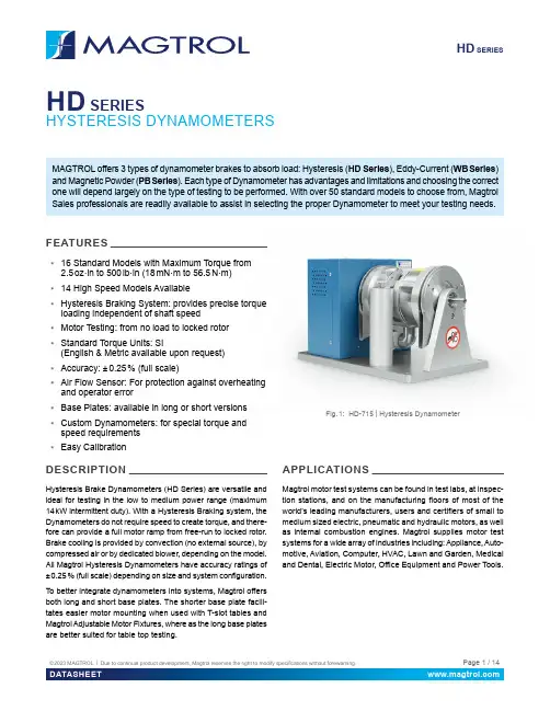
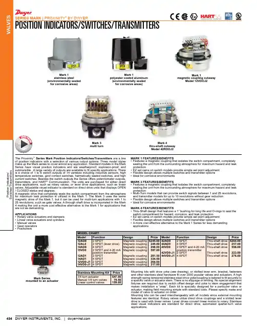
HD SERIES HD SERIESHYSTERESIS DYNAMOMETERSMAGTROL offers 3 types of dynamometer brakes to absorb load: Hysteresis (HD Series), Eddy-Current (WB Series) and Magnetic Powder (PB Series). Each type of Dynamometer has advantages and limitations and choosing the correct one will depend largely on the type of testing to be performed. With over 50 standard models to choose from, Magtrol Sales professionals are readily available to assist in selecting the proper Dynamometer to meet your testing needs.FEATURES▪16 Standard Models with Maximum Torque from2.5 oz·in to 500 lb·in (18 mN·m to 56.5 N·m)▪14 High Speed Models Available▪Hysteresis Braking System: provides precise torqueloading independent of shaft speed▪Motor Testing: from no load to locked rotor▪Standard Torque Units: SI(English & Metric available upon request)▪Accuracy: ± 0.25 % (full scale)▪Air Flow Sensor: For protection against overheatingand operator error▪Base Plates: available in long or short versions▪Custom Dynamometers: for special torque andspeed requirements▪Easy CalibrationDESCRIPTIONHysteresis Brake Dynamometers (HD Series) are versatile and ideal for testing in the low to medium power range (maximum 14 kW intermittent duty). With a Hysteresis Braking system, the Dynamometers do not require speed to create torque, and there-fore can provide a full motor ramp from free-run to locked rotor. Brake cooling is provided by convection (no external source), by compressed air or by dedicated blower, depending on the model. All Magtrol Hysteresis Dynamometers have accuracy ratings of ± 0.25 % (full scale) depending on size and system configuration. To better integrate dynamometers into systems, Magtrol offers both long and short base plates. The shorter base plate facili-tates easier motor mounting when used with T-slot tables and Magtrol Adjustable Motor Fixtures, where as the long base plates are better suited for table top testing.APPLICATIONSMagtrol motor test systems can be found in test labs, at inspec-tion stations, and on the manufacturing floors of most of the world’s leading manufacturers, users and certifiers of small to medium sized electric, pneumatic and hydraulic motors, as well as internal combustion engines. Magtrol supplies motor test systems for a wide array of industries including: Appliance, Auto-motive, Aviation, Computer, HVAC, Lawn and Garden, Medical and Dental, Electric Motor, Office Equipment and Power Tools.Fig. 1: HD-715 | Hysteresis DynamometerMagtrol’s Hysteresis Dynamometers cover a wide range of Torque, Speed and Mechanical Power ratings. To select the appropriate size Dynamometer for your motor testing needs, you will need to determine the Maximum Torque, Speed and Power applied to the Dynamometer.MAXIMUM TORQUEThe Magtrol Hysteresis Absorption Dynamometer will develop braking torque at any speed point, including low speed and stall conditions ("0" rpm). It is important to consider all torque points that are to be tested, not only rated torque, but also locked rotor and breakdown torque. Dynamometer selection should initially be based on the maximum torque requirement, subject to determining the maximum power requirements. MAXIMUM SPEEDThis rating is to be considered independent of torque and power requirements, and is the maximum speed at which the Dynamometer can be safely run under free-run or lightly loaded conditions. It is not to be considered as the maximum speed at which full braking torque can be applied.MAXIMUM POWER RATINGSThese ratings represent the maximum capability of the Dyna-mometer Braking System to absorb and dissipate heat gener-ated when applying a braking load to the motor under test. The power absorbed and the heat generated by the Dynamometer is a function of the Torque (T) applied to the motor under test, and the resulting Speed (n) of the motor. This is expressed in these Power (P) formulas:The Dynamometer’s ability to dissipate heat is a function of how long a load will be applied. For this reason, the maximum power ratings given are based on continuous operation under load, as well as a maximum of 5 minutes under load.To safely dissipate heat and avoid Dynamometer failure, the maximum power rating is the most important consideration in selecting a Dynamometer.Magtrol Hysteresis Dynamometers absorb power with a unique Hysteresis Braking Systemwhich provides frictionless torque loading independent of shaft speed. The HysteresisBrake provides torque by the use of two basic components - a reticulated pole structureand a specialty steel rotor/shaft assembly - fitted together but not in physical contact.Until the pole structure is energized, the drag cup can spin freely on its shaft bear-ings. When a magnetizing force from the field coil is applied to the pole structure,the air gap becomes a flux field and the rotor is magnetically restrained, providinga braking action between the pole structure and rotor.Magtrol’s M-TEST Software isa state-of-the-art motor testingprogram for Windows®-baseddata acquisition. Used with aMagtrol DSP 7010 Dynamom-eter Controller, Magtrol M-TESTSoftware provides the control ofany Magtrol Dynamometer and runs test sequences in a manner best suited to the overall accuracy and efficiency of the Magtrol Motor T est System. The data that is generated by Magtrol’s Motor T esting Software can be stored, dis-played and printed in tabular or graphic formats, and can be easily imported into a spreadsheet.Written in LabVIEW™, M-TEST has the flexibility to test a majority of motor types in a variety of ways. Because of LabVIEW’s versatility, obtaining data from other sources (e.g. thermocouples), controlling motor power and providing audio/visual indicators is relatively easy. Magtrol’s M-TEST Software is ideal for simulating loads, cycling the unit under test and motor ramping. Because it is easy to gather data and duplicate tests, the software is ideal for use in engineering labs. T ests can be programmed to run on their own and saved for future use allowing for valuable time savings in production testing and incoming/outgoing inspection.SI: P[W] = T[N·m] × n[min-1]× (1.047 x 10-1) English: P[W] = T[lb·in] × n[rpm]× (1.183 x 10⁻²) Metric: P[W] = T[kg·cm] × n[rpm]× (1.027 x 10⁻²) All of Magtrol’s controllers, readouts and software calculate horsepower as defined by 1 [hp] = 550 [lb·ft /s].Using this definition:P[hp] = P[W] / 745.7Pole StructureBearingAir GapOPEN LOOP SYSTEMSMagtrol offers both open loop manual test systems and PC-based closed loop test systems. A typical open loop system will consist of a Dynamometer and a Magtrol DSP 7010 Dynamom-eter Controller in Open-Loop configuration. A Magtrol Single or Three-Phase Power Analyzer, which allows for the capturing of volts, amps, watts and power factor, can be included as an option. An open loop system is often used for quick pass / fail testing on the production line or at incoming inspection. Magtrol’s DSP 7010 Dynamometer Controller provides pass / fail testing as a standard feature.CLOSED LOOP SYSTEMSIn a closed loop motor test system, data is collected on a PC using Magtrol’s M-TEST Software, DSP 7010 Dynamometer Controller, and requisite interface cards and cables. Magtrol’s DSP 7010 Dynamometer Controllers compute and display mechanical power (in horsepower or watts) in addition to torque and speed. A Single or Three Phase Power Analyzer, a required component in a test system measuring motor efficiency, can be integrated into this system as well as Magtrol’s Temperature Testing Hardware.MODEL 7500Computer witha) All -5C dynamometers are 5 Volt Output.Please, contact our sales representative for 6C (English units), 7C (Metric units) or 8C (SI units) specifications.b) Operating at the continuous power rating for periods of up to 4 hours isacceptable. However, operating for extended periods at high temperatures will result in premature component and bearing failure. Limiting the length of the cycle and the component temperatures will guard against premature failure. Where continuous duty is desired for longer time intervals, compo-nent temperatures should be maintained less than 100°C; monitoring the outside brake surface temperature is a sufficient reference.c) Requires air cooling provided by user. Regulator and filter package isprovided as standard d) Blower is includede) The maximum speed will depend on what type of keyway (if any) is usedon the shaft. Unless specified, the dynamometer shaft will be made withouta keyway.ELECTRICAL POWERHD-100 / 400 / 500 SERIES WITH LONG BASE PLATEb) Shaft Flats are not available on high speed models.a) These dimensions represent the distance between mounting holes. Thereare four (4) mounting holes on each base plate.HD-100 / 400 / 500 SERIES WITH SHORT BASE PLATEb) Shaft Flats are not available on high speed models.a) These dimensions represent the distance between mounting holes. Thereare four (4) mounting holes on each base plate.a) These dimensions represent the distance between mounting holes. Thereare four (4) mounting holes on each base plate.b) Shaft Flats are not available on high speed models.are four (4) mounting holes on each base plate.a) These dimensions represent the distance between mounting holes. There are four (4) mounting holes on each base plate.BLOWER POWER▪Models HD-710, HD-715 & HD-810 include the BL-001 blower.▪Models HD-815 include the BL-002 blower. ▪Model HD-825 uses two BL-002 blowers for cooling its two brake sets.On / Off Switch120/240 V AC / 50/60 HzAllow approximately 6 in to 8 in (152 mm to 203 mm) between rear of dynamom-eter base plate and blower for connection hardware. Required hardware is sup-plied with the dynamometer.BL-002 Blower has two filter elements.HD 106 & HD 106 HSHD-100 & HD 100 HSHD 400 & HD 400 HSHD 500 & HD 500 HS30 00040 00050 00060 000Maximum Rated Speed for standard versionMaximum Rated Speed for High Speed version m )0.0000.0020.0040.0060.0100.0120.0140.0160.018010 00020 00030 00040 00050 00060 000S P E E D (r p m )TORQUE (N·m )0.000.010.020.030.040.050.060.070.085 00010 00020 00025 00030 00035 00040 00045 00015 000S P E E D (r p m )TORQUE (N·m )HD 510 & HD 510 HSHD 505 & HD 505 HSHD 515 & HD 515 HSHD 700 & HD 700 HSHD 710 & HD 710 HSHD 705 & HD 705 HS5 00010 00020 00025 00030 00015 00035 00040 00045 0000.10.00.20.30.40.50.60.70.8S P E E D (r p m )TORQUE (N·m )0.000.250.500.751.001.251.505 00010 00020 00025 00030 00015 00035 00040 00045 000S P E E D (r p m )TORQUE (N·m )0.000.250.500.751.001.251.505 00010 00020 00025 00030 00015 00035 00040 00045 000S P E E D (r p m )TORQUE (N·m )0.00.5 1.0 1.5 2.0 2.5 3.05 00010 00020 00025 00030 00015 00035 00040 000S P E E D (r p m )TORQUE (N·m )0.00.51.01.52.02.53.0 05 00010 00020 00025 00030 00035 00040 00015 000S P E E D (r p m )0.01.02.03.04.05.06.05 00010 00020 00025 00030 00015 00035 00040 000S P E E D (r p m )HD 715 & HD 715 HSHD 800HD 805HD 810 & HD 810 HSHD 815 & HD 815 HSHD 825 & HD 825 HS0.01.02.03.04.05.06.0 05 00010 00020 00025 00030 00040 00035 00015 000S P E E D (r p m )TORQUE (N·m)0.02.0 4.0 6.08.012.010.014.04 000 2 0006 00010 00012 00014 0008 000S P E E D (r p m )TORQUE (N·m)0.05.010.015.020.025.02 0004 0006 0008 00010 00012 00014 000S P E E D (r p m )TORQUE (N·m )0.02.0 4.08.06.010.012.014.04 000 2 0006 00010 00012 00014 00016 0008 000S P E E D (r p m )TORQUE (N·m )0.05.010.015.020.025.04 000 2 0006 00010 00012 00014 00016 0008 000S P E E D (r p m )TORQUE (N·m )0.010.020.030.040.050.02 0004 0006 0008 00012 00010 000S P E E D (r p m )TORQUE (N·m )The power absorption curves represent the maximum power (heat) that the dynamometer can dissipate over time.HD SERIESHD Series Hysteresis Dynamometers can be incorporated into a Customized Motor Test System (CMTS )These PC based, turn-key systems arecustom designed and built to meet specific user requirements.Various devices such as dynamometer con-trollers, power analyzers or other customized devices can be easily integrated into a 19" rack system (in an external cabinet or directly in the table).These systems integrate specific software (such as M-TEST) to facilitate the measure-ment process.ENCODER OPTIONS FOR LOW SPEED TESTINGFor low speed motors, such as gear motors with maximum speeds of less than 200 rpm, Magtrol offers additional encoder options that allow for increased resolution of the speed signal.T-SLOT BASE PLATETo accommodate Magtrol AMF-3 Adjustable Motor Fixtures, a grooved base plate with three M12 T-slots, one centered and two 250 mm apart, is available on all HD-8XX series dynamometers.MECHANICAL CUSTOMISATIONSMagtrol is highly experienced and qualified in the customization of its products. We can provide custom-ized base plates, riser blocks and shaft modifications.Our specialized salesmen and technicians are at your service to help you find the best configuration for your project.a) In case of special design the 4 last digits will be specific; please contactour sales representative b) Please contact our sales representative regarding long base plate c) PPR means Pulse Per RevolutionExample: HD Series Dynamometer, model 106, supply in 240 V A C, shortbase plate, 60-PPR encoder and standard version would be ordered as follows: HD-106-5C2-0100HD Series Dynamometer, model 805, supply in 120 V A C, long base plate with T-slot, 6000-PPR encoder and high speed version would be ordered as follows: HD-805-5C1-024HCABLE ASSEMBLYa) Other lenght available on requestDynamometer TableBlowerAdjustable Motor FixtureMotor Under TestHeavy-duty Equipment RackFully customizable (19" rack standards)Control screen(optional touchscreen)Command Panel(allows easy access to the main functions)Connection Panel To connect external devices or options spe-cific to the test bench (temperature probe,...)DSP 7010 Series Dynamometer Controller MODEL 7500 SeriesPower AnalyzerFull Computer (inlcuding rack mounted keyboard,...)Free rack mounted spacefor third-party equipment (e.g. power supply, measuringinstrument, etc...)© 2023 MAGTROL | Due to continual product development, Magtrol reserves the right to modify specifications without forewarning.Page 14 / 14DATASHEETI E S - U S 06 / 2023HD SERIESSYSTEM OPTIONS AND ACCESSORIESDSP 7010 - DYNAMOMETER CONTROLLERSMagtrol’s MODEL DSP 7010 Series Dynamometer Controller employs state-of-the-art Digital Signal Processing Technol-ogy to provide superior motor testing capabilities. Designed for use with any Magtrol Hysteresis, Eddy-Current or Powder Dynamometer, Magtrol In-Line Torque Transducer or auxiliary instrumentation, the DSP 7010 can provide complete PC control via the USB or IEEE-488 interface. With up to 500 readings per second, the DSP 7010 is ideally suited for both the test lab and the production line.WB & PB SERIES - DYNAMOMETERThe WB Series (eddy current) and PB Series (magnetic powder) dyna-mometers are particularly suitable for demanding applications requiring low (PB) to high (WB up to 65 000 rpm) speeds. The PB brakes will develop their nominal torque atstandstill, while the WBbrakes develop a braking torque proportional to the speed and their maximum torque is reached at nominal speed. The brake is cooled by water circulating in the stator. As a result, these dynamometers are able to dissipate high continuous loads (up to 140 kW). The WB and PB dynamometers incorporate a torque measuring system which has an accuracy of ± 0.3 % to ± 0.5 % at full scale.MODEL 7500 - POWER ANALYZERSThe Magtrol MODEL 7500 Power Analyzer is an easy-to-use instrument ideal for numerous power measurement applications. From DC to 80 kHz, the MODEL 7500 measures volts, amps, watts, volt-amps, frequency, crest factor, Vpeak, Apeak and power factor in one convenient display. They may be used either as stand-alone instruments or in conjunction with any Magtrol Hysteresis, Eddy-Current or Powder Brake Dynamometer; any Magtrol Dynamometer Controller and M-TEST Software for more demanding motor test applications.AMF SERIES - MOTOR FIXTURESPositioning and alignment have a great influence on the measured parameters (friction torque). MAG-TROL strongly recommends a sup-port specifically dedicated to the products to be tested to ensure the best positioning tolerances in X-Y , and its repeatability.Alternatively, Magtrol AMF Series (Adjustable Motor Fixtures) can be used. These extremely versatile fixtures can accommodate motors up to 101 m m (4") in diameter. It enables easy motor centering during testing, but does not have centering references.TAB SERIES - DYNAMOMETER TABLESTest from a stationary position or move a dynamometer to alternate testing stations with ease with Magtrol’s Dynamometer Table. The stand is designed from lightweight aluminum with casters for smooth mobility, and is sturdy enough to support even the heaviest of Magtrol dynamometers. The design can be retrofitted to any Magtrol dynamometer and is easily reconfigured for added versatility.Fig. 7: DSP 7011 | Programmable Dynamometer ControllersFig. 8: 1 PB 115 | Powder DynamometerFig. 9: MODEL 7510 | Power AnalyzersFig. 10: T AB Series | Dynamometer Tables。
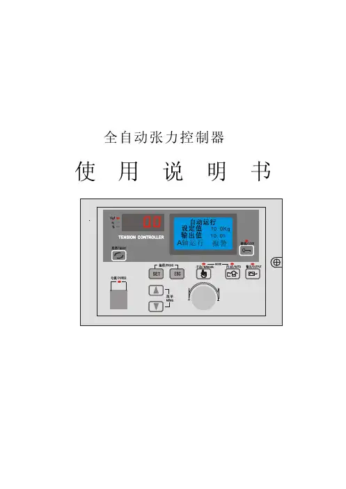
全自动张力控制器使用说明书()请务必在使用之前阅读5在打开控制器准备安装和接线之前要断开控制器电源至少要分钟。
正确的配置和安装是控制器正常运行的前提。
对以下几点要特别注意:●容许保护等级:保护接地,只有正确连接保护接地,才能减少外界电磁干扰。
●安装工作必须在无电状态下进行。
●与电网断开后,要等电容放电完毕,才可进行操作。
●不要让任何异物进入驱动器内。
●在使用前,要除去所有覆盖物,以防止装置过热。
●切勿在易燃易爆等危险环境中使用。
●请勿将该产品安装在高温、潮湿等恶劣环境下。
●请勿将产品直接安装在易受震动冲击的环境中。
系列张力控制器是一种高精度数字式可以自动控制卷材张力的自动控制仪器,它可以控制材料的放卷、送料、牵引及收卷张力。
1.1概述D/A 0.1%/●采用高精度转换器,输出精度可达,张力控制更精确。
●可以直接驱动磁粉(电磁)离合器制动器,也可控制变频、伺服等。
●可以接收单路或双路传感器输入信号,自动标定。
●外壳坚固美观,更具有很强的防电磁干扰功能。
接线安装方便。
自动调零,●人性化界面设计,操作十分方便。
●多行液晶显示,中英文菜单,编程简单,方便明了。
●内有密码功能,可以避免误操作改变设定参数。
●带有备份功能,可以将各种参数进行备份。
1.2功能及特点KTC2808●5)LCD 显示器(4)功能设置键(3)电源指示灯)手动控制模式键)自动控制模式键14)输出ON /OFF 键[1] 键锁定键:(1)(8(72) 键锁定指示灯)手动控制模式指示灯)自动控制模式指示灯)输出ON /OFF 键指示灯[2]监视显示切换键:(8)[3]输出ON /OFF :14键()[4]菜单切换键:(16)[5]自动控制模式11键:()[6]手动控制模式12键:()禁止变更设定。
用于显示的项目切换到监视显示器(7)上。
每按键一次,对控制输出进行ON /OFF .每按键一次,输出则重复进行ON --OFF -ON .读出菜单中存储的运行数据.按下自动控制模式键则切换到自动控制模式,LCD 显示器上按下手动控制模式键则在LCD 显示器上显示手动设定画面,手张力(N 或Kg /输出(%)切换一次示张力设定画面,自动控制模式指示灯(10)点亮.可利用数值设定刻度盘(16)进行张力定值的设定.动控制模式指示灯(10)点亮,随后可进行手动运转.1.3 操作界面1)壁挂式安装2)壁挂式安装的螺纹孔尺寸壁挂式安装面板镶嵌式安装的面板切口尺寸平面、立面安装定位孔4M-4244+3-0.5800.5+-172.52-41404-M4*12安装螺钉面板镶嵌式安装2.1 安装CPU 0.5~0.8Nm 系列张力控制器的工作电源为通电前要确认电源电压正确,以免损害控制器.[1]在张力控制器以外应安装急停电路,如果张力控制器出现故障,可以切断供电电源,以保证安全。
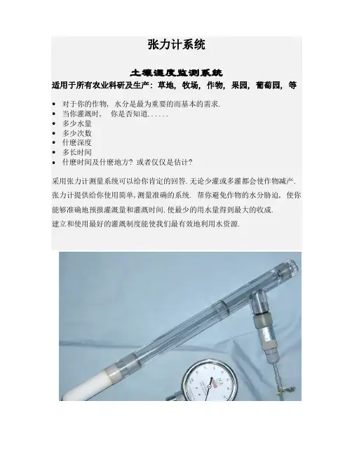
张力计使用说明及注意事项一、性能与特点张力计是反映土壤墒情状况,指导灌溉最好的仪器设备由ABS管或U—PVC管、多孔陶土头、集气管、真空表和其它附件组成。
ABS管或U—PVC管一端接陶土头,另一端接集气管,在集气管侧面安装真空表,集气管上端是注水口,当注满水后用橡皮塞将注水口塞紧,并将盖子拧紧,以防漏气。
真空表为模合型,精度为2.5级,是专门为该张力计设计制造的精密仪器。
表盘内用不同颜色表示。
l 黄色:表示水分太多,土壤的透气性差。
当指针长时间处于这个范围内时,作物不能正常生长,需要排水。
l 绿色:土壤水分状况最佳。
对于大部分温室栽培的经济作物来说,在这个范围内生长最好,不需要灌溉。
l 兰色:土壤水分状况良好。
对于大部分露天栽培的经济作物来说,在这个范围内会生长良好,不需要灌溉;对于温室作物来说,当张力计指针到了这个范围后就需要灌溉了。
l 红色:土壤水分状况差。
对于大部分经济作物来说,都需要灌溉,否则会影响产量和品质。
参数:环境温度:-20℃~85℃精度:0.25%扬程:-0.1Mpa二、安装埋设方法1、在需要测量土壤水势(墒情)的地方,用一直径20mm的钻孔器打孔至所需深度,然后往孔中加少许泥浆,垂直抽入张力计,使陶土头与土壤紧密接触,把周围填土捣实,并注入少许水,使松散土沉实,不能有间隙,保证雨水或灌溉水不会沿管壁下渗而失去代表性。
2、除去集气管上端的螺旋盖和橡皮塞,然后由注水口加满蒸馏水,塞紧橡皮塞,拧紧螺旋盖,不能漏气。
3、安装好的张力计经过2天时间的稳定,仪器内的水与土壤水就可产生水力联系,便可进行使用。
注1:在农业生产中使用时,如果没有蒸馏水,也可加入干净的普通饮用水,测出的值会有一些误差,但对作物的生长影响不大。
注2:如果作为科研仪器使用,为了保证仪器的灵敏度,必须把陶土头真空表内的空气排净,方法为:(1)排除陶土头的空气:先除去集气管上端的螺旋盖和橡皮塞,然后由注水口加入蒸馏水,加满后让水从陶土头表面溢出约10分钟左右,陶土头内的空气就排净了。

负压式土壤湿度计(张力计)使用说明书一、原理与特点土壤湿度计是测定土壤水分的一种仪器。
众所周知,土壤水分受土壤孔隙的毛管引力和土粒的分子引力的作用,使土壤孔隙中的水分处于负压(吸力)状态,土壤吸力愈大,土壤孔隙中的水分愈少,土壤含水量也就愈低;反之,土壤吸力愈小,土壤孔隙中的水分愈多,则土壤含水量愈高。
所以土壤湿度计指示的数据就能大致反应出土壤的含水量状况,负压试土壤湿度计(也称张力计)就是测定这种土壤吸力(或称土壤基质势)的仪器。
负压式土壤湿度计由陶土头、腔体、集气室、计量指标器等部件组成。
陶土头是仪器的感应部件,具有许多微小的孔隙,陶土头被水浸润后,在孔隙中形成一层水膜。
当陶土头中的孔隙全部充水后,孔隙中水就具有张力,这种张力能保证水在一定压力下通过陶土头,但阻止空气通过。
当充满水且密封的土壤湿度计插入水分不饱和的土壤时,水膜就与土壤水连接起来,产生水力上的联系。
土壤系统的水势不相等时,水便由水势高处通过陶土头向水势低处流动,直至两个的系统的水势平衡为止。
当忽略了重力势、温度势、溶质势后,系统的水势即为压力势和基质势之和,土壤的压力势(以大气压力参考)为零,仪器里无基质,基质势为零,土壤水的基质势便可由仪器所示的压力(差)来量度。
非饱和土壤水的基质势抵于仪器里的压力势,土壤就透过陶土头向仪器吸水,直到平衡为止。
因为仪器是密封的,仪器中就产生真空度或吸力(抵于大气参照压力的压力)。
这样仪器内的负压便计量器或传感器测行,这就是土壤的吸力。
土壤水吸力与土壤水基质势在数值上是相等的,只是符号相反,在非饱和土壤中,基地势为负值,吸力为正值,张力计较多地用于非饱和土壤上,其基质势为负值,矿张力计又称负压计。
土壤水吸力是土壤水势的强度指标和土壤水的流动,对植物的有效性有密切的关系。
与土壤含水率的含义不同,它是在土壤水势的强弱上面不是在多寡上反映土壤的干湿程度。
一般来说,土壤吸力愈大含水量愈小;土壤吸力愈小含水量愈多。
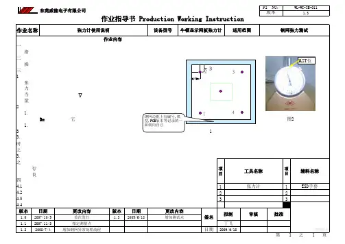
一、 目的指导作业员正确使用张力计,并正确读取钢网张力大小,以免钢网不良影响产品品质。
二、 作业准备 操作人员必须准备好一块水平板平放于工作台面上,以减小测量误差。
三、作业步骤 1 在每次测量钢网之前必须由技术员(或组长以上级别的管理员)对 张力计进行校正零位,具体校正方法如下:从张力计箱中轻取出张力计,并将玻璃面平放于水平平板上,将张力计平放于玻璃面上,当指针转到2½圈后指‘RST’时,则张力计已校正零位,可以开始测量钢网。
如右图2:2 钢网张力测试选点位置为:钢网四个角及钢网中心点.如右图1中所示.1.1 四角选点位置与钢网边框的距离为10CM. A=B=10CM 其它三点的标准一样 1.2 中心点位置为钢网中间点. 3 具体测量步骤如下:图13.1 将待用钢网反向平放于平板上,将张力计正立轻放于钢网左角上(朝水平方向放置),此时可以看到指针已旋转两圈,当指针停止在一刻度时才开始读数:(具体读数必须从开始旋转到第二圈开始读数(第一圈数值忽略),读数值为:36+初始读数(初始读数为指针旋转到第二圈后36 之后的读数即为初始读数)3.2 当测完第一个角的张力后,继续依次按以上步骤测量其他测试点的读数;四角的张力同时都在35N/CM~50N/CM之间且中间点张力在30N/CM~50N/CM 之间则为合格钢网,可以生产,若张力不在此范围中则为不良钢网,应通知工程、品保人员进行评估,若不影响品质则限次使用,在限次使用时必须要定时检查钢网表面是否变形,破损不良则做报废处理停止使用。
(1KG=9.8N)四、注意事项4.1 测量钢网张力必须由技术员(或组长以上级别的管理员)进行,不许其他人员误操作。
11 4.2 张力计必须轻拿轻放,不得摔,抛等动作。
224.3 非专业人员不得任意调节张力计,此张力计出厂已校正零位。
334.4 在每次钢网使用完毕之后必须对其进行一次测量,以检查生产过后是否符合要求。

皮带张力计的使用方法之答禄夫天创作
●
●工作原理
当一个力作用到皮带上, 皮带起初会在多种模式中振动, 可是高频率振动要比基础频率振动衰减的更快.这样, 保管下来的连续正弦波形对应了皮带的张力.
通过抓取皮带的自然振动频率, 而且经过微电脑处置相关数据, 很容易就得出对应频率下的振动曲线.
新系统使用特殊探头来丈量皮带振动曲线表, 探头接收的数据会发送到仪器里的微型电脑中进行处置并转换为自然频率.为了计算皮带张力, 系统使用横向的振动弦理论, 所以必需输入质量, 切线长和宽度.
公式:T=4×M×W×S2×F2×10-9
T= 切线张力(牛顿)
M= 质量(gf/m/mm)
W= 宽度或楔数
S= 切线长度
F= 频率
皮带有横向张力, 所以丈量的张力值可能会比实际值要高, 取决于使用的环境, 当需要获得更精确土地带实际张力时, 必需要有一个简单的刻度测试.
使用方法
按下“丈量”键, 绿色的LED灯会开始闪动, 拍打皮带使皮带振动, 把探头放在离皮带1厘米(0.4英寸)左右, 可是请勿碰到皮带, 绿色的LED灯将不竭闪动直到探头接收到信号, 这时LED灯会自动关失落, 屏幕上将呈现一个曲线图.在信号接收后, 丈量的张力会显示出来, 丈量仪会响三声, LED灯提示你丈量胜利.看完张力陈说后, 按下HZ键保管显示屏上的张力, 频率.
如果皮带不能丈量, 或者丈量频率或计算的张力在仪器范围外, 红色的LED灯会亮.此时丈量无论是张力还是频率都可能是毛病的.。
高真空值读数表明土壤干燥. 读数
偏低则表明土壤湿润. 通常,在灌溉区域
应布置一定数量的监测点.每一个点应有
顶盖 2-3支不同长度的张力计管.这样不仅可
以了解每个点不同深度的水分含量而且
可以了解水分在灌溉期间的运移情况 .
该张力计系统仅需少量维护便可多年
可靠使用. 仪表毋需标定和置零 .
使用时在田间定期直读并记录.
例如每周2--3次. 然后绘制成土壤水分
运动图. 测试结果应与从农业部门了解
到的不同作物需水量结合, 使灌溉者能
够估计出下一个灌溉周期的需水量以及
能在灌溉日的前几天做好准备.
张力计测量系统
张力计是一种较为简单的仪器.它可以测量
土壤中任意点的土壤湿度情况.
仪器操作简单,易于保养.是一种用于灌溉管
理的可靠仪器.该张力计系统具有下列优点
土壤张力计由两个部分组成: 低价格的测管. 这意味着可以设置较多
∙张力计探测管-- 由聚碳酸酯管和透气陶的观测点. 易于更换补充.
瓷头加密封橡胶塞组成. 在管内注入适量水不锈钢指针直读仪表用于各张力计探测管的后埋入土壤中使用. 读数直观,快速,准确无误.
∙仪表--非常准确的不锈钢指针直读仪表.采用耐侯性聚碳酸酯探管,强度高,寿命长. 用于从探测管读数.各部件均可拆卸,易于更换维护。
标准探测管长度为15--90CM(测量深度)工作原理可以满足大部分情况的使用要求.
当土壤变干, 与陶瓷头接触的湿度表面特殊长度可根据用户要求加工.
张力势趋于将管内的水分吸出. 从而在管内注意: 探管内用水应为冷却后的开水.
顶部形成局部真空.当灌溉或降雨后,水分被新探管使用前应排空气泡.
吸回管内使真空度减少.。
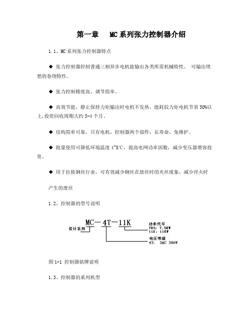
第一章 MC系列张力控制器介绍1.1、MC系列张力控制器特点◆ 张力控制器控制普通三相异步电机能输出各类所需机械特性。
可输出理想的卷绕特性。
◆ 张力控制精度高,调节简单。
◆ 高效节能,静止保持力矩输出时电机不发热,能耗较力矩电机节省50%以上,投资回收周期大约3-4个月。
◆ 结构简单可靠,只有电机、控制器两个部件,长寿命,免维护。
◆ 批量使用可降低环境温度4~8℃,提高电网功率因数,减少变压器增容投资。
◆ 用于拉拔钢丝行业,可有效减少钢丝在放丝时的夹丝现象,减少淬火时产生的废丝1.2、控制器的型号说明图1-1 控制器铭牌说明1.3、控制器的系列机型表1-1 控制器系列机型说明第二章控制器的安装及端子配线2.1、控制器的外形尺寸图2-1 控制器外形图表2-1 控制器外形尺寸2.2、控制器的端子功能及配线2.2.1 产品端子配置图2-2 MC-4T7R5及以下功率等级图2-3 MC-4T11K及以上功率等级2.2.2主回路端子功能MC-4T1R5~MC-4T15KR/L1 S/L2 T/L3 ⊕1⊕2/B1B2 ? U/T1 V/T2 W/T3端子符号端子名称及功能说明R/L1、S/L2、T/L3 三相交流输入端子⊕1、⊕2/B1直流电抗器连接端子,出厂时用铜排短接⊕2/B1、B2 制动电阻连接端子⊕1、 ? 直流电源输入端子;外置制动单元的直流输入端子U/T1 、V/T2、 W/T3 三相交流输出端子2.2.3 端子配线图2-4 端子配线图(以MC-4T7R5为例)A、控制回路端子功能分类端子符号功能说明数字输入+24V +24VPLCX1 启动信号输入端子COM +24V地,X1的公共端模拟输入+10V 模拟输入参考电压(上表和配线图中未涉及的端子为厂家预留的端子,请勿接线,否则可能会发生误动作,危害人生及设备生产安全!)第三章操作面板使用说明3.1操作面板按键说明3.2操作实例下例为将设定电机极数为6级电机的实际操作步骤。
二. 目录1. 重要事项 (2)2. 使用说明 (4)3. 工作原理 (10)4. 皮带质量表 (11)5. 皮带安装张力 (13)6. 使用技巧 (13)7. 非标皮带的张力计算 (15)8. 特点 (15)9. 配件 (15)10.保修期、售后服务 (16)感谢您购买皮带张力计U507,使用之前请仔细阅读使用手册·请勿撞碰,任何冲撞都会导致此产品损坏。
·请勿把水、溶剂及其它任何液体泼洒在此产品上。
·请勿把此产品放置在多灰的环境中。
·避免此产品受热,比如汽车里或者直接的光照。
·请勿使用易挥发的溶剂清洗此产品。
·请勿在有火花的地方使用,否则可能引起爆炸。
·请勿拉探头任意两端的线绳。
·请勿在有雷雨的室外使用此产品,关掉电源并寻找一个安全的地方使用,否则有可能遭雷击。
·便携式探头是管状结构,请勿将探头弯折成锐角,不要在任意两端20mm(3/4英寸)的地方和两端尖部弯曲。
皮带张力计U507使用说明:安装探头把探头上的卡槽和仪器上的凹槽连接并推紧。
如需分离,握住探头上的卡槽然后拔出。
打开电源按下电源键,LCD会出现如下图面:1- Mass “皮带单位质量”2- Width “皮带宽度”3- Span “切线长”4- No. 储存代码5- 频率设定6- 电池容量在光线暗的情况下,LCD背景灯会打开,若5分钟内无操作,会自动关机。
打开的屏幕上显示的是上次关机时使用的数据。
1代表皮带单位质量,2代表皮带宽度,3代表皮带测量区域对应的切线长,这些数据都是同时显示的。
备注皮带参数必须要输入仪器中,以便得出皮带张力。
不管皮带的质量是多少,仪器都会显示频率值,但是会显示“错误”,如果计算的皮带张力值超出屏幕显示的值,红色灯会一直亮着。
(4)指的是当前皮带数据的储存设定号,如需更改数据或储存设定,请看皮带参数数据的储存及恢复。
(5)指的是当前频率设定,如需更改,请看第7页的频率设定。
CHV系列模块化矢量型变频器选配件张力卡使用说明书1、型号与规格1.1型号说明选配件张力卡的型号为CHV00ZL。
CHV系列变频器装配上张力卡,就具备进行收、放卷的恒张力控制。
同时,张力卡也提供RS485物理通讯模式可供用户进行通讯控制。
1.2 外型示意图图1.1 通讯卡外型示意图1.3 安装示意图图1.2 通讯卡安装示意图2、张力卡端子说明3、跳线说明跳线名称跳线说明J1电压(0~10V )/电流(0~20mA )输入切换跳线。
1(V )、2(GND )短接为电压输入; 2(GND )、3(I )短接为电流输入S1RS485通讯口终端器设置选择。
拨码开关ON :采用终端器;拨码开关OFF :不用终端器。
当该RS485通讯端口位于RS485通讯网络电缆的末端时,需使用终端器4、端子的排列顺序示意图5、CHV 张力控制功能说明5.1 前言在工业生产的许多领域中,都需要进行精确的张力控制,保持驱动设备输出张力的恒定,以提高产品质量。
比如造纸、纸加工、印刷、印染、包装、电线电缆、光纤光缆、胶带制造、纺织、皮革、金属箔材料加工等等,在这些行业的收、放卷工艺中,都需要保持收、放(线端子名称端子用途及说明S6~S8开关量输入端子,与PW 和COM 形成光藕隔离输入输入电压范围:9~30V 输入阻抗:3.3K ΩHDI2高速脉冲或开关量输入,与PW 和COM 形成光藕隔离输入 脉冲输入频率范围:0~50KHz输入电压范围:9~30V 输入阻抗:1.1K ΩCOM 为+24V 或者外部电源的公共端。
AI3模拟量输入,电压范围:-10V ~10V 输入阻抗:10K ΩAI4 模拟量输入,电压(0~10V )/电流(0~20mA )通过J1可选。
输入阻抗:10K Ω(电压输入)/250Ω(电流输入) RS485+,RS485-RS485串行通讯材、带材)上张力的恒定。
5.2产品介绍CHV张力控制卡,依附于CHV系列高性能矢量变频器基础之上,在功能算法中,增加了张力控制专用模块,实现面向中心收卷、放卷等工艺场合的专用张力控制变频器功能,如放卷、中间段、收卷等工艺段全套解决方案。
目 录1.关于安全注意2.概要,注意事项及测定不良时的确认事项3.U-505张力器的原理4.U-505张力器各部件说明5.U-505张力器操作顺序6.输入数值的方法6-1 输入单位数值的方法6-2 Belt宽度或Belt原始数值的输入6-3 Span长度的输入7.UNITTA产Timeing Belt规格一览表8.KEITU产V型Belt规格一览表9.UNITTA产齿轮Belt标准值一览表10.U-505的规格一览11.After-sales service的保证1.关于安全注意■请在使用之前必须认真阅读安全注意事项之后正确操作。
■该注意事项是为了未然防止操作员及周围人的安全而制定的,因此务必遵守。
■下列标识说明了不当操作可能会导致的危害和损害。
■下列标识区分了遵守规定的程度不同。
表示不能进行操作,“禁止”的意思。
表示必须要实行,是“强制内容”避免冲击及抛出。
禁止分解,改造。
·故障,引发火灾的原因 ·火灾,中伤,触电的原因 禁止在易燃易爆场所内使用 不能与水、溶剂等接触。
·丙烷,汽油等易燃易爆性环Mic禁止在有水、油的环境操作有误时会有生命及受重伤的危险。
操作有误时会有生命及受重伤的可能性。
操作有误时可能会受伤及损害物品。
境中使用可引发爆炸,火灾 中使用。
使用前必须确认切断发动机 在室外使用时,遇到雷雨天气电源及设备的停止状态。
请切断电源后移到安全的地方。
保管时勿放在湿度重,灰尘 修理时勿用稀释剂、汽油。
多,高温的场所。
勿放在摇晃、倾斜、不安定 Brake Arm式Mic的Arm部分是自主 的场所。
式pipe,所以不能强度的弯曲。
·避免掉下来时伤人 另不要弯曲Mic前端20毫米处和 请勿在直射光线,热天气下 Connector的下端;Mic(sensor) 的车内等高温环境中使用。
及Arm部;Code式Mic和·机械变形,故障的原因 电磁sensor2.概要,注意事项及测试不良时的确认事项■概要音波式Belt张力器(U-505)是把与Belt机能有最大关系的取付张力,利用音波解析简单正确的测出张力的装置。
产品使用说明手册AZGH 绳索张力计使用说明书产品使用说明书一、概述1.1主要用途及适用范围AZGH 绳索张力计是一款在线测量电线电缆、光纤和绳索等张力的仪器,适宜在高铁行业、电力行业、通信行业、交通运输行业、建筑行业、游乐场等凡涉及铜绞线张拉力测量时使用。
也适用于各大科研院校、检测机构等场合。
1.2产品特点1.2.1在线测量:测量绳索时绳索不需拆卸,可在线测量具有张紧力的绳索,实时加载绳索张力时,可在线观察实时张力。
1.2.2便携式:仪器采用高强度铝合金结构,重量轻、体积小、携带方便,测量绳索张力时,一人便可完成所有操作。
1.2.3 操作方便:仪器加载机构采用杠杆结构,只需要将仪器手柄推到底就可以正确测量绳索张力;操作简便,一个人在30秒内就可完成一次测量。
1.2.4 仪器性能稳定,测量精度高,当被测绳索规格与测力计中储存的绳索号一致时,在可定量程内,测量精度可达5%。
1.2.5仪器内置3种预设规格绳索,测量时只需选择相应的绳索号即可。
1.2.6数显显示力值,仪器采用LCD 显示测量力值,读数更加方便。
1.2.7三种单位切换:仪器可切换N 、Kgf 和Lbf 三种力值。
1.2.8仪器可保存383组测量数据,保存的数据可通过电脑导出。
1.3 品种、规格1.3.1 铜绞线张力计内置规格表1.3.1.1 AZGH-A-5000G 绳索张力计内置规格如下表:线径(mm) 满量程(N) 铜绞线 铜绞线 1 φ7.5 5000 2 φ9 5000 3φ10.55000指标被测物 索引1.3.1.2 AZGH-B-5000G 绳索张力计内置规格如下表:线径(mm) 满量程(N) 铜绞线 铜绞线 1 φ10.5 5000 2 φ12.5 5000 3φ1450001.3.1.3 AZGH-C-5000G 绳索张力计规格如下表: 线径(mm)满量程(N)1 φ12.5 50002 φ14 5000 3φ1650001.3.2 钢丝绳张力计内置规格表1.3.2.1 AZGH-A-5000S 绳索张力计内置规格如下表:线径(mm) 满量程(N) 钢丝绳 钢丝绳 1 φ6 5000 2 φ8 5000 3φ105000被测物 索引指标 铜绞线铜绞线指标被测物 索引被测物 索引指标1.3.2.2 AZGH-B-5000S 绳索张力计内置规格如下表:线径(mm) 满量程(N) 钢丝绳 钢丝绳 1 φ10 5000 2 φ11 5000 3φ1350001.3.2.3 AZGH-C-5000S 绳索张力计规格如下表: 线径(mm) 满量程(N)1 φ11 50002 φ13 5000 3φ1650001.4产品技术参数 1.4.1分度值:1N 1.4.2精度:±5%1.4.3电源:7.2V 镍氢电池组1.4.4 充电器:输入AC 100~240V 50Hz 输出:DC 12V 500mA 1.4.5 采样率:10Hz 1.5型号的组成及其代表意义产品使用说明书被测物 索引被测物 索引钢丝绳钢丝绳指标指标二、产品整体结构2.1 外形结构二、产品整体结构2.2 液晶屏功能2.2.1开关机键:按此键时,电源打开或关闭。
凯特测量技术有限公司KTB数显张力计使用说明书产品概述:KTB系列数显式张力计是新一代通用型便捷式低功耗张力测试仪器。
具有体积小、量轻、容易携带、多功能、高精度等特点,适用于继电器接点压力、电子开关、微型自动电话设备接点和衔铁压力等机械压力、磁带录音机缓冲装置压力等接触点压力和张紧力的测试。
●产品特性:测量范围:1N~50N;负荷分度值:0.001N或0.01N;示值误差:0.5%;单位转换:N,kgf,lbf上下限报警值可设定,声音报警;存储100组测试数据,并自动计算存储数据的平均值、最大值、最小值操作界面中文英文显示可选择工作环境温度\存储环境温度:0℃~40℃/-20℃~70℃;电源:锂电3.6V/270mAh/Lion3.6V/270mAh;外形尺寸:146mm×52mm×24mm;注:另配有上位机软件安装光盘,可使本产品通过USB数据线与计算机连接,以多种显示方式并对数据进行处理,如打印、统计等。
●规格:型号规格KTB-1 KTB-2 KTB-5 KTB-10 KTB-20最大测量值1N0.1kg0.22b2N0.2kg0.44lb5N0.5kg1.1lb10N1kg2.2lb20N2kg4.4lb负荷分度值0.001N0.1g0.0002lb0.001N0.1g0.0002lb0.001N0.1g0.0002lb0.005N0.5g0.001lb0.01N0.001kg0.002lb相对示值误差0.5%单位牛顿、公斤、磅电源锂电3.6V/270mah工作温度0℃-40℃储存温度-20℃-70℃相对湿度15%-80%工作环境周围无振动及腐蚀性介质。