继电器DS2继电器
- 格式:pdf
- 大小:41.31 KB
- 文档页数:1
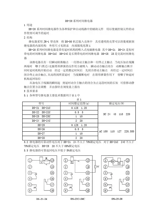
DS-20系列时间继电器1 用途DS-20系列时间继电器作为各种保护和自动线路中的辅助元件 用以使被控制元件的动作得到可调节的延时2 结构继电器采用JK-1型壳体 将DS-30机芯装入壳体中 具有透明的壳罩可以清楚观察到继电器的内部结构 外形尺寸见附录 内部接线见图1DS-20系列时间继电器是带有延时机构的吸入式电磁继电器 其中DS-21 DS-24是短时带电的时间继电器 DS-21C DS-24C 是长期带电的时间继电器 DS-25 28是交流时间继电器该继电器具有一付瞬动转换触点 一付滑动主触点和一付终止主触点 当电压加在线圈两端时 唧子(铁芯)克服塔形弹簧的反作用力被吸入 瞬动动合触点闭合 动断触点断开 同时延时机构开始启动 经过一定的整定时间后 先闭合滑动主触点 再经过一定时间后 闭合终止动合触点,从而得到所需延时 当线圈断电时 在塔形弹簧作用下 使唧子和延时机构返回原位从加电压于线圈的瞬间起 到延时动合主触点的闭合为止这段时间的长短 可借移动静触点位置方法调整 并由指针在刻度盘上指出3 技术要求3.1 各种型号继电器主要技术数据列于表1中 表1型号时间整定范围(s) 额定电压(V)DS-21 DS-21C0.125 1.25 DS-22DS-22C 0.5 5 DS-23 DS-23C1 10 DS-24 DS-24C2 20 DC 24 48 110 220 DS-250.125 1.25 DS-260.5 5 DS-271 10 DS-282 20 AC 100 110 127 220,380 3.2 继电器的可靠动作电压对于DS-21 24不大于70%额定电压 对于DS-21C 24C 不大于75%额定电压 DS-25 28不大于85%额定电压3.3 继电器的可靠返回电压不低于5%额定电压图1 DS-20系列时间继电器内部接线图(正视)3.4 继电器主触点延时一致性不大于表2中的规定表2型号整定时间(s) 延时一致性(s) DS-21 DS-21C DS-25 1.25 0.06DS-22 DS-22C DS-26 5 0.125DS-23 DS-23C DS-27 10 0.25DS-24 DS-24C DS-28 20 0.5注(1) 延时一致性是指在同一整定上测量10次中最大和最小动作时间之差(2) 第3.2 3.4条中规定的参数是指在环境温度20 5 的条件下3.6 在额定电压下的功率消耗对于DS-21 24不大于25W 对于DS-25 28不大于20VA 对于DS-21C DS-24C不大于15W4 使用与维护4.1 使用者应注意继电器的额定工作方式若将短时工作的继电器用于线圈回路长期带电的场合则继电器线圈必过热而损坏长期工作继电器有外附电阻在使用时应按附图1中Rf的位置接入4.2 继电器应装在与水平面垂直的屏板上并且在投入运行前应使继电器通电动作以免由于各运动部位不能复归至原位而引起延时的误差4.3 继电器在维修时其钟表机构部分各零件应使用航空汽油清洗之后在各可动部位(滑动接触部位)点以适量4#航空仪表油在电磁直接带动的凸轮与扇形齿板间涂以低温脂电磁部分动铁芯及线圈管中应擦试清洁附注随产品供给长期工作继电器的外附电阻及安装件。

`AMCB2使用维护手册西子奥的斯电梯有限公司 编号:XAA610BB_GL_ZH`记录:Copyright 2006, OTIS GmbH Berlin.No part of this document may be copied or reproduced in any form or by any means without the prior written consent of OTIS GmbH.`目录1 概述 ........................................................................4 2 AMCB2硬件说明:...............................................................5 2.1 LCD显示器 。
.............................................................6 2.2 操作按钮.................................................................7 2.3 输入输出端口定义义也不同.................................................8 3 运行时序.....................................................................12 3.1 检修运行................................................................12 3.2 正常运行................................................................13 3.3 复位运行................................................................14 3.4 井道自学习运行..........................................................15 3.5 端站超速保护............................................................16 4 参数介绍:...................................................................17 4.1 FO系统参数..............................................................17 4.2 F1 ̄F6运行曲线...........................................................17 4.3 楼层速度相关参数........................................................18 4.4 平层调整参数............................................................19 4.5 称重调整参数............................................................20 4.6 抱闸延时调整............................................................21 5 其它功能参数.................................................................21 6 故障说明及解决方案:.........................................................22 `1 概述AMCB2板子适用于OH-CON4421/3控制系统,主要用于XO-STAR和OH5000电梯上。
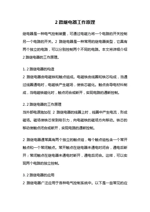
2路继电器工作原理继电器是一种电气控制装置,可通过电磁力将一个电路的开关控制另一个电路的开关。
2路继电器是一种常用的继电器类型,它具有两个独立的电路,可以分别控制两个不同的电路。
本文将详细介绍2路继电器的工作原理。
1. 2路继电器的构造2路继电器由电磁铁和触点组成。
电磁铁由线圈和铁芯构成,当通过线圈通电时,电磁铁产生磁场,使铁芯磁化。
触点由导电材料制成,当电磁铁磁化时,触点闭合或断开,实现电路的通断控制。
2. 2路继电器的工作原理当外部电源施加在2路继电器的线圈上时,线圈中产生电流,形成磁场。
磁场使铁芯受到吸引力,向电磁铁的磁场方向移动。
铁芯的移动使触点闭合或断开,实现电路的通断控制。
2路继电器通常具有两个独立的触点组,每个触点组包含一个常开触点和一个常闭触点。
常开触点在继电器未通电时闭合,通电后断开;常闭触点在继电器未通电时断开,通电后闭合。
这样,可以实现两个电路的独立控制。
3. 2路继电器的应用2路继电器广泛应用于各种电气控制系统中。
以下是一些常见的应用场景:3.1 照明控制2路继电器可用于照明系统的自动控制。
通过设置不同的触点组接线方式,可以实现多种照明模式的切换,如手动控制、自动控制、定时控制等。
3.2 电机控制2路继电器可用于电机的正反转控制。
通过控制触点组的闭合和断开,可以实现电机的正转、反转和停止。
3.3 家电控制2路继电器可用于家电产品的控制,如空调、电视、冰箱等。
通过触点组的控制,可以实现家电的开关、定时等功能。
3.4 安全控制2路继电器可用于安全控制系统,如防火、防盗等。
通过触点组的控制,可以实现报警器的启动、关闭等操作。
4. 2路继电器的特点2路继电器具有以下特点:4.1 独立控制2路继电器具有两个独立的触点组,可以分别控制两个不同的电路,实现独立控制。
4.2 通断可靠2路继电器采用触点闭合和断开的方式实现电路的通断控制,具有较高的可靠性和稳定性。
4.3 体积小巧2路继电器通常采用小巧的封装形式,体积小,安装方便。
![DS1E-M-DC48V系列继电器]](https://uimg.taocdn.com/81e0fa1514791711cc7917f0.webp)
18635.241.387.390DS1E15.5909.9.390DS2E20.787.390FEATURES• High sensitivity: 200 mW pick-up power100 mW pick-up power types available• Latching types available• High switching capacity: 60 W, 125 V A• High breakdown voltage: 1,500 V FCC surge between open contacts1,000 V AC between open contacts• DIP-1C type can be used with 14 pin IC socket2C type can be used with 16 pin IC socket,4C type can be used with 2 sets of 14 pin IC sockets • Gold-cap silver palladium types available for 2 Form C type • Bifurcated contacts are standardSPECIFICATIONSContact* Gold capped silver-palladium contact also available for 2 Form C 10 7 operations at 0.1 A 50 V DC resistiveCoil (polarized) (at 20 ° C 68 ° F )* For 1 Form C high sensitive types.Characteristics (at 20 ° C 68 ° F )Arrangement 1 Form C, 2 Form C, 4 Form C Initial contact resistance, max.(By voltage drop 6 V DC 1 A)50 m ΩContact material Gold-clad sliverRating(resistive)Max. switching power 60 W, 125 VA Max. switching voltage 220 V DC, 250 V AC Max. switching current 2 A DC, ACMax. carrying current 3 A DC, AC Expected life (min.operations)Mechanical (at 600 cpm)10 8(1 Form C 2 coil latching type: 10 7 )Electrical 2 A 30 VDC resistive5 × 10 5M type Single side stableMinimum operating power Approx. 200 mW Nominal operating powerApprox. 400 mW1 coil latchingMinimum set and reset power Approx. 90 mW Nominal set and reset power Approx. 180 mW 2 coillatching Minimum set and reset power Approx. 180 mW Nominal set and reset power Approx. 360 mWS type Single sidestableMinimum operating powerApprox. 100 mW (128 mW)* Nominal operating power Approx. 200 mW 1 coil latchingMinimum set and reset power Approx. 45 mW (58 mW)* Nominal set and reset power Approx. 90 mW2 coillatching Minimum set and reset power Approx. 90 mW (115 mW)* Nominal set and reset power Approx. 180 mWMax. operating speed20 cpm at rated load 50 cps at low level load Initial insuration resistance* 1Min. 100 M Ω (at 500 V DC)Initialbreak-down volt-age* 2Type of relay(DS1-S type)(Other types)Between open contacts 500 Vrms 1,000 VrmsBetween contacts sets—1,000 Vrms Between contacts and coil1,000 Vrms 1,500 Vrms FCC surge voltage between contacts and coil1,500 V (Expect DS1-S type)Operate time* 3 (at nominal voltage)Approx. 3 ms Release time (without diode)* 3(at nominal voltage)Approx. 2 ms Set time* 3 (at nominal voltage)Approx. 3 msReset time* 3 (at nominal voltage)Approx. 3 ms Temperature rise(at nominal voltage, Contact current: 2A) Max. 65 ° CShock resistanceFunctional* 4 1C, 2C:Min. 490 m/s 2 {50 G}4C:Min. 294 m/s 2 {30 G}Destructive* 5 Min. 980 m/s 2 {100 G}Vibration resistanceFunctional* 610 to 55 Hzat double amplitude of 3.3 mmDestructive10 to 55 Hzat double amplitude of 5 mmConditions for operation, transport and storage* 7(Not freezing and condens-ing at low temperature) Ambienttemp.–40 ° C to +70 ° C –40 ° F to +158 ° FHumidity 5 to 85% R.H.Unit weight 1 Form C Approx. 3.2g .11oz 2 Form C Approx. 4g .14oz 4 Form CApprox. 7g .25ozFCC (Federal Communication Commission) re-quests following standard as Breakdown Voltagespecification.Remarks*Specifications will vary with foreign standards certification ratings.* 1 Measurement at same location as "Initial breakdown voltage" section * 2 Detection current: 10 mA* 3 Excluding contact bounce time* 4 Half-wave pulse of sine wave: 11ms; detection time: 10 µ s * 5 Half-wave pulse of sine wave: 6ms * 6 Detection time: 10 µ s* 7 Refer to 5. Conditions for operation, transport and storage mentioned in AMBIENT ENVIRONMENT (Page 61)mm inchDS187TYPICAL APPLICATIONS• T elecommunication equipment • Office equipment• Computer peripherals • Security equipment• Measuring instrumentationORDERING INFORMATIONTYPESSingle side stable1 coil latching2 coil latchingNotes:1. Reverse polarity types available (add suffix-R).2. Standard packing: carton: 50 pcs.; case: 500 pcs.Nominal Voltage, V DCPart No.1 Form C 2 Form C 4 Form C M (400 mW) type1.5DS1E-M-DC1.5V DS2E-M-DC1.5V DS4E-M-DC1.5V 3DS1E-M-DC3V DS2E-M-DC3V DS4E-M-DC3V 5DS1E-M-DC5V DS2E-M-DC5V DS4E-M-DC5V 6DS1E-M-DC6V DS2E-M-DC6V DS4E-M-DC6V 9DS1E-M-DC9V DS2E-M-DC9V DS4E-M-DC9V 12DS1E-M-DC12V DS2E-M-DC12V DS4E-M-DC12V 24DS1E-M-DC24V DS2E-M-DC24V DS4E-M-DC24V 48DS1E-M-DC48V DS2E-M-DC48V DS4E-M-DC48V S (200 mW) type1.5DS1E-S-DC1.5V DS2E-S-DC1.5V DS4E-S-DC1.5V 3DS1E-S-DC3V DS2E-S-DC3V DS4E-S-DC3V 5DS1E-S-DC5V DS2E-S-DC5V DS4E-S-DC5V 6DS1E-S-DC6V DS2E-S-DC6V DS4E-S-DC6V 9DS1E-S-DC9V DS2E-S-DC9V DS4E-S-DC9V 12DS1E-S-DC12V DS2E-S-DC12V DS4E-S-DC12V 24DS1E-S-DC24V DS2E-S-DC24V DS4E-S-DC24V 48DS1E-S-DC48VDS2E-S-DC48V DS4E-S-DC48VNominal Voltage, V DCPart No.1 Form C2 Form C4 Form CM (180 mW) type1.5DS1E-ML-DC1.5V DS2E-ML-DC1.5V DS4E-ML-DC1.5V 3DS1E-ML-DC3V DS2E-ML-DC3V DS4E-ML-DC3V 5DS1E-ML-DC5V DS2E-ML-DC5V DS4E-ML-DC5V 6DS1E-ML-DC6V DS2E-ML-DC6V DS4E-ML-DC6V 9DS1E-ML-DC9V DS2E-ML-DC9V DS4E-ML-DC9V 12DS1E-ML-DC12V DS2E-ML-DC12V DS4E-ML-DC12V 24DS1E-ML-DC24V DS2E-ML-DC24V DS4E-ML-DC24V 48DS1E-ML-DC48V DS2E-ML-DC48V DS4E-ML-DC48V S (90 mW) type1.5DS1E-SL-DC1.5V DS2E-SL-DC1.5V DS4E-SL-DC1.5V 3DS1E-SL-DC3V DS2E-SL-DC3V DS4E-SL-DC3V 5DS1E-SL-DC5V DS2E-SL-DC5V DS4E-SL-DC5V 6DS1E-SL-DC6V DS2E-SL-DC6V DS4E-SL-DC6V 9DS1E-SL-DC9V DS2E-SL-DC9V DS4E-SL-DC9V 12DS1E-SL-DC12V DS2E-SL-DC12V DS4E-SL-DC12V 24DS1E-SL-DC24V DS2E-SL-DC24V DS4E-SL-DC24V 48DS1E-SL-DC48VDS2E-SL-DC48V DS4E-SL-DC48VNominal Voltage, V DCPart No.1 Form C2 Form C4 Form CM (360 mW) type1.5DS1E-ML2-DC1.5V DS2E-ML2-DC1.5V DS4E-ML2-DC1.5V 3DS1E-ML2-DC3V DS2E-ML2-DC3V DS4E-ML2-DC3V 5DS1E-ML2-DC5V DS2E-ML2-DC5V DS4E-ML2-DC5V 6DS1E-ML2-DC6V DS2E-ML2-DC6V DS4E-ML2-DC6V 9DS1E-ML2-DC9V DS2E-ML2-DC9V DS4E-ML2-DC9V 12DS1E-ML2-DC12V DS2E-ML2-DC12V DS4E-ML2-DC12V 24DS1E-ML2-DC24V DS2E-ML2-DC24V DS4E-ML2-DC24V 48DS1E-ML2-DC48V DS2E-ML2-DC48V DS4E-ML2-DC48V S (180 mW) type1.5DS1E-SL2-DC1.5V DS2E-SL2-DC1.5V DS4E-SL2-DC1.5V 3DS1E-SL2-DC3V DS2E-SL2-DC3V DS4E-SL2-DC3V 5DS1E-SL2-DC5V DS2E-SL2-DC5V DS4E-SL2-DC5V 6DS1E-SL2-DC6V DS2E-SL2-DC6V DS4E-SL2-DC6V 9DS1E-SL2-DC9V DS2E-SL2-DC9V DS4E-SL2-DC9V 12DS1E-SL2-DC12V DS2E-SL2-DC12V DS4E-SL2-DC12V 24DS1E-SL2-DC24V DS2E-SL2-DC24V DS4E-SL2-DC24V 48DS1E-SL2-DC48VDS2E-SL2-DC48VDS4E-SL2-DC48VDS188COIL DATA (at 20 ° C 68 ° F )Single side stable1 coil latching2 coil latchingNominal voltage,V DCPick-up voltage, V DC (max.)Drop-out voltage, V DC(min.)Coil resistance, Ω ( ± 10%)Maximum allowable, V DC (at 50 ° C 122 ° F )1 Form C 2, 4 Form C1 Form C 2, 4 Form C Mtype1.5 1.05 1.050.15 5.63 1.82.253 2.1 2.10.322.53.64.55 3.5 3.50.562.567.56 4.2 4.20.6907.299 6.3 6.30.920310.813.5128.48.4 1.236014.4182416.816.8 2.4144028.8364833.633.6 4.8576057.672S type1.5 1.2 1.050.1511.32.433 2.4 2.10.345 4.865 4.03.50.51258.01064.8 4.20.61809.61297.2 6.30.940514.418129.68.4 1.272019.2242419.216.8 2.4288028.4484838.633.64.81152076.896Nominal voltage, V DCReset Set, V DC (max.)Coil resistance, Ω ( ± 10%)Maximum allowable, V DC (at 50 ° C 122 ° F )1 Form C 2, 4 Form C1 Form C 2, 4 Form C M type1.5 1.05 1.0512.5 1.8 2.253 2.1 2.1503.64.55 3.5 3.513967.56 4.2 4.22007.299 6.3 6.345010.813.5128.48.480014.4182416.816.8320028.8364833.633.61280057.672S type1.5 1.2 1.05252.433 2.4 2.1100 4.865 4.03.52788.01064.8 4.24009.61297.2 6.390014.418129.68.4160019.2242419.216.8640038.4484838.433.62560076.896Nominal voltage, V DCReset Set, V DC (max.)Coil resistance, Ω ( ± 10%)Maximum allowable, V DC (at 50 ° C 122 °F )1 Form C 2,4 Form CCoil lCoil ll1 Form C 2,4 Form C M type1.5 1.05 1.05 6.25 1.82.253 2.1 2.1253.64.55 3.5 3.569.467.56 4.2 4.21007.299 6.3 6.322510.813.5128.48.440014.4182416.816.8160028.8364833.633.6640057.672S type1.5 1.2 1.0512.5 2.433 2.4 2.150 4.865 4.03.51398.01064.8 4.22009.61297.2 6.345014.418129.68.480019.2242419.216.8320038.4484838.433.61280076.896DS189DIMENSIONSmm inch1 Form CSingle side stable, 1 coil latching, 2 coil latchingGeneral tolerance: ± 0.3 ± .012PC board pattern (Copper-side view)Single side stable, 1 coil latching 2 coil latchingT olerance: ± 0.1 ±.004Schematic (Bottom view)Single side stableDeenergized condition1 coil latchingDiagram shows the "reset" position when terminals 1 and 6 are energized.Energize with reverse polarity to transfer contacts. 2 coil latchingDiagram shows the "reset" position when terminals 3 and 6 are energized.Energize terminals 1 and 3 to transfer contacts.2 Form CSingle side stable, 1 coil latching, 2 coil latchingGeneral tolerance: ± 0.3 ± .012PC board pattern (Copper-side view)Single side stable, 1 coil latching 2 coil latchingT olerance: ±0.1 ± .004Schematic (Bottom view)Single side stableDeenergized condition1 coil latchingDiagram shows the "reset" position when terminals 1 and 16 are energized.Energize with reverse polarity to transfer contacts. 2 coil latchingDiagram shows the "reset" position when terminals 2 and 15 are energized.Energize terminals 1 and 16 to transfer contacts.DS1904 Form CSingle side stable, 1 coil latching, 2 coil latchingGeneral tolerance: ± 0.3 ± .012PC board pattern (Copper-side view)Single side stable, 1 coil latching2 coil latchingTolerance: ± 0.1 ±.004Schematic (Bottom view)Single side stableDeenergized condition1 coil latchingDiagram shows the "reset" position when terminals 1and 16 are energized.Energize with reverse polarity to transfer contacts. 2 coil latchingDiagram shows the "reset" position when terminals 2 and 15 are energized.Energize terminals 1 and 16 to transfer contacts.REFERENCE DATA1. Maximum switching capacity2. Life curve (Resistive load)3. Contact reliability for AC loadsSample: DS2E-M-DC24V 10 pcs.Cycle rate: 20 cpm.Detection level: 200 m Ωmm inchDS4-(1). Coil termperature rise(2 Form C single side stable type)Point measured: Inside the coilAmbient temperature: 18° to 19°C 64° to 66°F4-(2). Coil tempeature rise(4 Form C single side stable type)Point measured: Inside the coilAmbient temperature: 17° to 18°C 63° to 64°F4-(3). Coil temperature rise(2 Form C 2 coil latching type)Point measured: Inside the coilAmbient temperature: 20° to 21°C 68° to 70°FFor Cautions for Use, see Relay Technical Information。
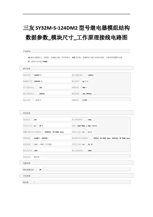
三友SY32M -S -124DM2型号继电器模组结构数据参数_模块尺寸_工作原理接线电路图 产品特性:
16A 触点切换能力。
功耗低,负载能力强。
外形体积小,PCB 式安装。
优越的电气耐久性和可靠性。
可提供单线圈和双线
圈。
环保产品(符合RoHS)。
电耐久性 100000次
最大切换功率
4000VA 机械耐久性 1000000次
触点材料 Ag 合金
最大切换电流 16A
接触电阻 50mΩ 最大切换电压 250VAC
额定负载 16A 250VAC 强度冲击 10G
最大释放时间
15ms 外形尺寸长(mm ) 29.1
振动 10Hz~55Hz 1.5mm 双振幅
线圈与触点间介质耐压 2000VAC ,50/60Hz 1min
外形尺寸宽(mm )
12.8 绝缘电阻 1000MΩ(500VDC )
断开触点间介质耐压 750VAC ,50/60Hz 1min ,2000VAC ,50/60Hz 1min 温度范围 -40℃~+70℃(不冷凝)
外形尺寸高(mm ) 25.45 稳定性冲击 100G
最大动作时间 15ms。
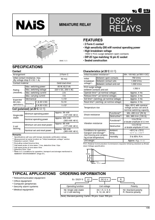
19520.787.3669.9.390FEATURES• 2 Form C contact• High sensitivity-200 mW nominal operating power • High breakdown voltage1500 V FCC surge between open contacts • DIP-2C type matching 16 pin IC socket • Sealed constructionSPECIFICATIONSInitial contact resistance, max.(By voltage drop 6 V DC 1 A) Max. switching power Max. switching voltage Max. switching currentMax. carrying current 1 A 30 V DC2 A 30 V DCTYPICAL APPLICATIONS• Telecommunication equipment • Office equipment• Computer peripherals • Security alarm systems • Medical equipmentORDERING INFORMATIONmm inchDS2Y196TYPES AND COIL DATA (at 20 ° C 68 ° F )Single side stable(Note) Standard packing: Carton: 50 pcs. Case: 500 pcs.2 coil latching(Note) Standard packing: Carton: 50 pcs. Case: 500 pcs.Nominal voltage, V DC Part No.Pick-up voltage, V DC (max.)Drop-out voltage, V DC (min.)Nominal operatingcurrentmA ( ± 10%)Coil resistance,Ω ( ± 10%)Nominaloperating power mWMaximum allow-able voltage, V DC (at 50 ° C 122 ° F )1.5DS2Y -S-DC1.5V 1.050.15132.711.320033DS2Y -S-DC3V 2.100.366.74520065DS2Y -S-DC5V3.50.540125200106DS2Y -S-DC6V4.20.633.3180200129DS2Y -S-DC9V 6.30.922.24052001812DS2Y -S-DC12V 8.4 1.216.77202002424DS2Y -S-DC24V 16.8 2.48.32,8802004848DS2Y -S-DC48V33.64.86.37,68030086Nominal voltage, V DC Part No.Reset set, V DC (max.)Nominal operating current mA ( ± 10%)Coil resistance, Ω( ± 10%)Nominal operatingpower, mW Maximum allow-able voltage, V DC(at 50° C 122 ° F )Set Reset Set Reset Set Reset 1.5DS2Y -SL2-DC1.5V 1.0512012012.512.518018033DS2Y -SL2-DC3V 2.16060505018018065DS2Y -SL2-DC5V 3.53636139139180180106DS2Y -SL2-DC6V 4.23030200200180180129DS2Y -SL2-DC9V 6.320204504501801801812DS2Y -SL2-DC12V 8.415158008001801802424DS2Y -SL2-DC24V 16.87.57.53,2003,2001801804848DS2Y -SL2-DC48V33.67.57.56,4006,40036036072DIMENSIONSmm inchSingle side stableGeneral tolerance: ± 0.3 ± .012PC board pattern (Copper-side view)Tolerance: ± 0.1 ± .004Schematic (Bottom view)(Deenergized position)2 coil latchingGeneral tolerance: ± 0.3 ± .012PC board pattern (Copper-side view)Tolerance: ± 0.1 ± .004Schematic (Bottom view)(Reset position)DS2YREFERENCE DATA1. Maximum switching capacity2-(1) Coil temperature rise (Single side stable)T ested sample: DS2Y -S-DC12V , 5 pcs.Measured portion: Inside the coilAmbient temperature: 21 ° C to 25 ° C 70 ° F to 77 ° F2-(2) Coil temperature rise 2 coil latchingTested sample: DS2Y -SL2-DC12V , 5 pcs.Measured portion: Inside the coilAmbient temperature: 21 ° C to 25 ° C 70 ° F to 77 °FFor Cautions for Use, see Relay Technical Information (Page 48 to 76).。
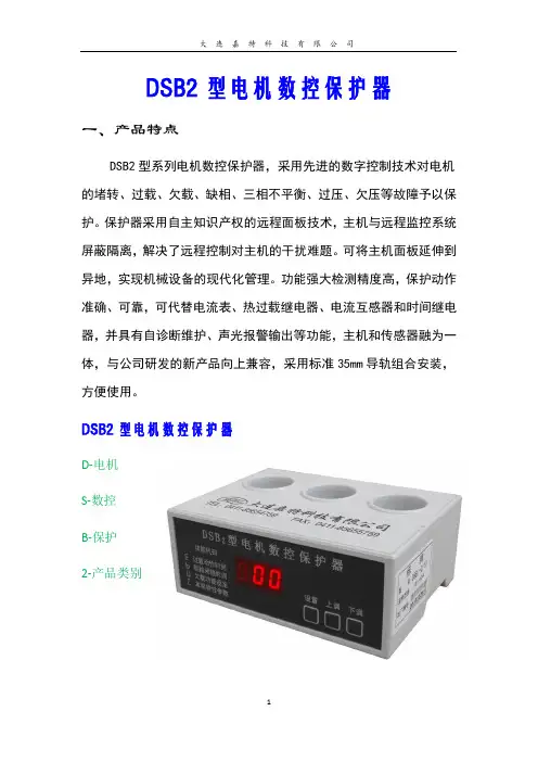
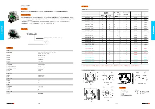
DSB2型电机数控保护器一、产品特点DSB2型系列电机数控保护器,采用先进的数字控制技术对电机的堵转、过载、欠载、缺相、三相不平衡、过压、欠压等故障予以保护。
保护器采用自主知识产权的远程面板技术,主机与远程监控系统屏蔽隔离,解决了远程控制对主机的干扰难题。
可将主机面板延伸到异地,实现机械设备的现代化管理。
功能强大检测精度高,保护动作准确、可靠,可代替电流表、热过载继电器、电流互感器和时间继电器,并具有自诊断维护、声光报警输出等功能,主机和传感器融为一体,与公司研发的新产品向上兼容,采用标准35mm导轨组合安装,方便使用。
DSB2型电机数控保护器D-电机S-数控B-保护2-产品类别二、技术参数1、工作电压:AC180V—420V 50Hz-60Hz;2、启动闭锁:避开启动电流,设定范围1s~99s;3、过载保护:运行电流>过载整定电流进入设定过载延时时间后动作,设定范围1s~99s ;4、反时限保护:运行电流>整定电流进入保护状态,动作时间与过载电流成反比,当运行电流>整定电流2倍时速断;5、短路保护:≤0.1s动作(根据用户需要特制);6、断相保护:≤3s动作(空载≤4s;满载≤2s);7、堵转保护:≤3s动作(运行电流≥整定电流2倍);8、欠载保护:运行电流<欠载整定电流进入倒计时状态,设定动作时间与过载保护动作时间相同, 倒计时后动作。
当运行电流>欠载整定值,进入正常运行状态。
9、电流显示:实际运行电流采用LED数字形式显示;10、分体传输接口:4-20MA接口、RS485接口附件可选,易操作11、报警输出:有报警输出接点,也可连接可编程控制器PLC ;12、故障代码:保护器动作后,(有不间断电源)在未复位启动前显示故障代码;13、复位方式:具有手动、自动及断电复位功能;14、触点容量:5A AC250V(阻性);15、机械寿命:>5×10⁴次;16、电气寿命:>5×10⁴次;17、环境温度:工作环境-15℃~65℃相对湿度≤85%;18、 防护处理:全封闭、防尘、防腐机芯;二、 型号选择:型号整定范围 4-20MA 扩展单元 产品名称规格型号 整定范围 电机数控保护器DSB2-A/01-10 0.1-10A DSB2-B/05-50 5-50A DSB2-C/15-60 15-60A DSB2-D/50-120 50-120ADSB2-E/CT1-5 120-650A(CT1-5A 自备)测控扩展单元 JTCK-4-204-20MA注:附件说明书见附表根据电机整定范围选择相应规格型号的保护器。
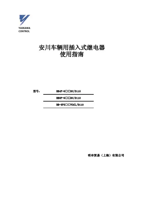
YASKAWACONTROL安川车辆用插入式继电器使用指南型号:RB4P-G□□DC/D110RB3P-G□□DC/D110RB-3P5□□V2CL/D110明幸贸易(上海)有限公司正向垂直壁面或垂直水平面壁面水平面标准产品规格书品名中容量元件内置型车辆用插入式继电器型号 RB4P-G□□DC/D1101.适用本规格书适用于中容量元件内置型车辆用插入式继电器(型号:RB4P-G□□DC/D110).2.外形图外形图如S44484所示。
3.规格书的构成本规格书由以下几个项目构成。
(1)规格(2)完成品的出货检查(3)标识以及包装规格(4)使用注意事项(5)其他(6)用语说明4.规格4.1操作线圈规格·特性*1.环境温度20℃下适用。
*2.使用温度范围(-40℃~+70℃)下适用。
4.2接点规格以及特性注)请参照表4 的用语。
5.完成品检查收到产品后,请按照下面的内容进行检查。
表3.完成品检查完成品检查成绩表在产品出厂后10年间,请品质管理科保管。
用于保证维护品质。
6.标识·包装规格1)产品的跟踪标准:在产品的侧面用黑色的TAT墨水印上2位的生产批次编码。
例如:“E5”……2010年5月的产品生产批次E:显示年(2010年是E,2011年是F,按照罗马字母顺序依次类推。
)5:显示月(1~9月是数字1~9,10月11月12月是字母XYZ)完成品检验合格后在包装箱上印上合格印记。
2)包装时要考虑到运输过程中可能遇到的破损以及雨水湿气的侵害情况,尽力避免。
7.使用注意事项1)请避免跌落。
万一跌落,请先检查玻璃破裂以及动作特性,确认无异常后再使用。
2)线圈有极性,请将端子符号①接在+极,将⑾接在-极。
此外,线圈驱动电源请使用电池电源的完全直流或者三相全波整流那样波动率5%以下的电源。
3)线圈驱动回路请使用施加额定电压的直投法(瞬时ON,瞬时OFF)。
线圈施加电压逐渐增大,以及逐渐减小的线圈驱动回路时,会造成电气寿命变短。
广日元件代码广日元件代码AVR 速度系统稳压电源CLN 轿厢串行通讯电子板DAP 减速触发电路板DCT、9ODCT 减速电流变流器DIV 减速控制电路板DS1、DS2 减速回路可控硅DSNュ 抗干扰线圈FLS(U) 上极限开关FLS(D) 下极限开关FML 平层感应器FMS 手动层高测定开关FRET 消防返回继电器SDS(U) 上终端减速开关SDS(D) 下终端减速开关SWG 脉冲整形电路板90/105-S 速度指令电路板H48A 输入输出电子扳HAD 起动补偿电子板HCTA 过电流检出HCTU 过电压检出HkRY 继电器保电子板HLN 厅外串行通信电子板HSDS 超声波探测器CP1 轿内指层信号 (触头) RE OPEN(U) 上行本层开门触头RE OPEN(D) 下行本层开门触头C.RES 内指令消除触头H.RES(U) 外上召消除触头H.RES(D) 外下召消除触头FRONT(U) 上超前层楼触头FRONT(D) 下超前层楼触头SD(U) 上行减速触头SD(D) 下行减速触头OPEN 开门区域触头DIRECT 单层信号检出(触头) DMA 方向选择(触头) FRONT 先行信号检出(触头) IND 轿外指层信号(触头)1X 起动锁住时间1X 快车一级加速时间辅助(TH梯) 2X 锁住检出时间2X 快车二级加速时间辅助(TH梯) 3 运行停车时间继电器 (TH梯) 3X 锁住检出限时4 非门区运行超时4X、4Y 非门区运行超时辅助5 门区运行超时6 慢车—级加速时间继电器(TH梯)6X、6Y 慢车—级时间辅助继电器(TH梯)7 慢车二级加速时间继电器(TH梯)7X 慢车二级时间辅助继电器 (TH梯)10、10X、1OY 运行继电器1OA、1OD 开门控制10A 运行继电器 (TH梯)1OD 运行辅助继电器 (TH梯)1OP、10R、1OS 运行中信号1OQ 休止信号10TZ 运行继电器11A 上行继电器 (TH梯)12A 下行继电器 (TH梯)11X、11Y、11Z 上方向指令及辅助12X、12Y、12Z 下方向指令及辅助13X 高速运行指令13 快车接触器14 低速运行(慢车接触器TH梯用)15B 抱闸接触器15BZ 抱闸继电器15D 减速电流2O 快车一级加速接触器21 快车二级加速接触器24 慢车一级加速接触器25 慢车二级加速接触器3O 消防基站继电器(TH梯)30DF、30FX 并联返基站检出30FK、3OFKX 单层返基站检出3OM 自发电返基站40、40X、40Y 轿门闭合及辅助40D、4ODX 层门联锁43B、43BX 司机专用43C 检修和低速运行指令43GA、43GAX 运行状态(轿内检修)43GB、43GBX 运行状态(快车状态)43GC 轿顶检修43LF 照明控制43GBY 工作状态43F、43FX 消防信号43LQX 3分钟无呼叫熄灯继电器43FQX 3分钟无呼叫熄风扇继电器45A 有选向信号继电器45C 并联内指令检出45H 有召唤信号继电器45HU 并联外上呼检出45HD 并联外下呼检出47 相序48A 定时关门计时48A 开门时间继电器 (TH梯) 48AX 开门时间辅助继电器48B 关门故障时间48C、48CX 并联援助服务48M、48T 援助服务中48H 定时关门指令48P 延时开门辅助继电器50 硬件回路安全50B 软硬件回路安全5OE、50EX 消防状态继电器(TH梯)50X 软件回路安全50M 开门故障继电器50T、50TX 电机过热保护51H、51M、51S 并联构成51E、51EX 消防专用状态继电器 (TH梯)60 并联运行61A 上方向61B 上方向辅助 (TH梯)61L、61LP 上方向辅助62A 下方向62B 下方向辅助 (TH梯)62L、62LP 下方向辅助65 重载直驶65W 超载信号65WC 半载检出65WL 重载检出65WQ 超载继电器 (TH梯)66 专用运行66F、66FX 消防专用90D 减速电机检出90DQ 选层触头过渡90M 电机电流检出90P 速度检测90PX 速度检测辅助91Aヘ91N 减速梯级构成91P、91PX 减速开始信号91LC 负载补偿减速平层控制器91LX 91L辅助91Q 平层信号继电器91U、92U 上行强迫换速继电器91D、92D 下行强迫换速继电器92 减速信号92A、92AX 单层检出及辅助92AP 单层信号保持92E 电机过热信号92D、92U 减速检出92L 故障不再运行92S 端站检出92Q 减速停车辅助控制继电器94A 低电压检测94A 过热保护辅助继电器(TH梯)94AH 热保护94B 门电动机热继电器94F 风机供电94FT 风机工作时间97 共用电源(主回路接触器) 97A 并接继电器97G、97GX 消防专用97L、97LX 休止熄灯97M 自发电起动97SA、97SAX 正常供电继电器97SBY、97SBYX 停电柜供电继电器98M 自发电返基站99E 底速自救指令100 开关门1O0T 关门辅助继电器1O0P 延时开门时间控制继电器100PH 延时开门时间辅助继电器101 关门指令1O2 开门指令102G 开门辅助继电器1O3 开门范围103F、103FY 开门区域继电器104 开门区检出104U 上方向本层开门继电器104D 下方向本层开门继电器100R 微动平层继电器。
JYJXC-220/220,有极加强接点继电器1 用途JYJXC-220/220型有极加强接点继电器(以下简称继电器)在信号电路中作道岔控制继电器。
2 适用环境继电器的适用环境为:a) 环境温度:-40℃~+60℃;b) 相对湿度:不大于90%(温度+25℃);c) 气压:不低于70 kPa(相当于海拔高度3000m以下);d) 振动: 振频不大于15Hz,振幅不大于0.45mm;e) 工作位置:水平;f) 周围无引起爆炸危险的有害气体,并应有良好的防尘措施。
3 机械特性接点组数:2DF、2DFJ;鉴别销号码:15、54;接点间隙:普通接点不小于4.5 mm;加强接点不小于7 mm;托片间隙:普通接点不小于0.35 mm;加强接点0.1 mm~0.3 mm;普通接点压力:定位接点不小于150 mN;反位接点不小于150 mN;加强接点压力:定位接点不小于400 mN;反位接点不小于400 mN;接点齐度误差:普通接点与普通接点间及普通接点与加强接点间不大于0.2 mm,加强接点与加强接点间不大于0.1 mm。
定位或反位保持力不小于2 N;3 电气特性(+20℃时)线圈电阻:线圈单独使用,使用1、23、4;额定值:;充磁值:;转极值:正向10V~16V、反向10V~16V;接点电阻:普通接点不大于0.05Ω;加强接点不大于0.1Ω。
5 绝缘耐压在试验的标准大气条件下,继电器的绝缘电阻应不小于100MΩ。
在气压不低于86kPa条件下(相当于海拔高度1000m以下),继电器的绝缘耐压应能承受交流正弦波50Hz、2000V有效值电压,历时1min 应无击穿闪络现象,重复试验时的电压应为原试验电压值的75%。
6 电寿命继电器普通接点通以DC 24V 1A 阻性负载;加强接点通以DC 220V 7.5A 、0.05H感性负载,JPXC-1000,偏极继电器1 用途JPXC-1000型偏极继电器(以下简称继电器)在信号电路中用于道岔表示电路以及单复线半自动闭塞电路。
lads2时间继电器原理时间继电器是一种常见的电气元件,用于控制电路在特定时间间隔内开关的状态。
它在各种电气控制系统中广泛应用,包括自动化、照明、电力设备、电动机控制等领域。
本文将详细介绍时间继电器的原理及其工作方式。
时间继电器的原理基于电磁感应和电磁力的作用。
它由一个电磁线圈和一个可控制动接点组成。
当电流通过继电器的线圈时,会在线圈内产生一个磁场。
这个磁场将吸引或排斥可控制动接点,从而改变电路的状态。
时间继电器通常包含两个主要部分:触点和电磁线圈。
电磁线圈由绝缘铜线绕成,当通过线圈的电流变化时,会在线圈周围产生磁场。
触点则由两个金属片组成,当电磁线圈产生磁场时,触点会因为磁力的作用而闭合或打开。
时间继电器的工作方式通常是通过一个控制电路来控制电磁线圈的电流。
控制电路中的开关或其他传感器可以检测到特定的条件,并在满足条件时启动或关闭电流。
当电流通过线圈时,磁场将吸引触点,使其闭合。
当线圈中的电流消失时,磁场也会消失,触点则会打开。
时间继电器的工作时间可以通过控制电流的时间来调节。
在继电器的电路中,通常会设置一个可调的电阻或电容来控制电流的流动速度。
通过调整电阻或电容的数值,可以改变电流通过线圈的时间,从而改变继电器的工作时间。
时间继电器的应用非常广泛。
在照明控制系统中,时间继电器可以用来控制灯光的开关时间,实现定时开关的功能。
在自动化系统中,时间继电器可以用来控制机械设备的启停时间,以提高生产效率。
在电力系统中,时间继电器可以用来保护电路,当电流超过设定值时自动断开电路,防止电路过载。
时间继电器的使用还需要注意一些问题。
首先,继电器的电磁线圈需要耗电,因此在选择继电器时需要考虑电流的大小,以免过载。
其次,继电器的触点需要定期维护和清洁,以确保其正常工作。
最后,继电器在工作过程中会产生一定的电磁干扰,需要与其他电路隔离以避免干扰。
总之,时间继电器是一种常见的电气元件,基于电磁感应和电磁力的原理工作。
六、交流二元继电器交流二元继电器中的二元指有两个互相独立又互相作用的交变电磁系统,根据频率不同,交流二元继电器分为25 Hz和50 Hz 两种。
JRJC 一66/345型和JRJC 1一70/240型二元继电器用于交流电气化区段的25 Hz 相敏轨道电路中作为轨道继电器。
它们由专设的25 Hz 铁磁分频器供电,具有可靠的频率选择性和相位选择性,对于轨端绝缘破损和不平衡造成的50 Hz 干扰能可靠地防护。
另外还有动作灵活的翼板转动系统、紧固的整体结构,不仅经久耐用,而且便于维修。
50 Hz 交流二元继电器主要用于地下铁道、矿山等直流牵引区段的轨道电路中作为轨道 继电器。
其结构和动作原理与25 Hz 交流二元继电器基本相同,只是线圈参数有所不同,以适应不同频率的需要。
本节介绍25 Hz 交流二元继电器,它们的基本情况如表1一10所列。
(一)、交流二元继电器的结构JRJC 1-70/240型交流二元继电器在JCJR 一65/345的基础上对结构进行改进设计。
采用 了增强整机结构稳定性和改进机械传动的形式;优化了磁路设计以增大电磁牵引力和改善了 机械电气性能;改进接点结构,改善接点性能;改变接点转动轴的结构以提高动作可靠性。
因此,在接点压力、返还系数、可靠性方面有了很大提高。
JRJC 1-70/240型交流二元继电器结构如图1一48所示。
由电磁系统、翼板、接点等主要部件组成。
1.电磁系统电磁系统包括局部电磁系统和轨道电磁系统。
局部电磁系统由局部铁芯和局部线圈组成。
轨道电磁系统由轨道铁芯和轨道线圈组成。
铁芯均由硅钢片叠成。
线圈是用高强度漆包线绕在线圈骨架上而构成的。
图1—46 JZCJ-0.16型继电器结构 图1—47 JZCJ-0.16型继电器电源片与接点位置 表1—10 交流二元继电器器基本情况2.翼板翼板是将电磁系统的能量转换为机械能的关键部件。
翼板由1 . 2 mm厚的铝板冲裁而成成,安装在主轴上。
DS2继电器
DS2继电器
产品型号: DS2Y/DS2E
产品简介:
NAIS:品 牌 :松下类 型 : 信号继电器系 列 : DS2Y系列型 号 : DS2Y-S-DC24V 外形尺寸(mm):
20.0×9.9×9.3mm(L×W×H)重 量 : 2g 触点参数:触点形式: 2C(DPDT)触点负载: 2A30VDC, 阻 抗: ≤50mΩ额定电流: 2A 电气寿命:≥10万回机械寿命:≥1亿回线圈参数: 阻值(士10%):2880Ω 线圈功耗:200mW 额定电压
:DC24V 吸合电压:DC 16.8V 释放电压:DC2.4V 工作温度:-40℃~+85℃ 绝缘电阻:≥1000MΩ 线圈与触点间耐压
:1000VAC/1分钟触点与触点间耐压:1000VAC/1分钟联系,具体系列
产品详细介绍:
NAIS:品 牌 :松下类 型 : 信号继电器系 列 : DS2Y系列型 号 :
DS2Y-S-DC24V 外形尺寸(mm): 20.0×9.9×9.3mm(L×W×H)重 量 : 2g
触点参数:触点形式: 2C(DPDT)触点负载: 2A30VDC, 阻 抗: ≤50mΩ 额定电流: 2A
电气寿命:≥10万回机械寿命:≥1亿回线圈参数: 阻值(士10%):2880Ω 线圈功耗:200mW 额定电压:DC24V
吸合电压:DC 16.8V 释放电压:DC2.4V 工作温度:-40℃~+85℃ 绝缘电阻:≥1000MΩ
线圈与触点间耐压:1000VAC/1分钟触点与触点间耐压:1000VAC/1分钟联系,具体系列
供应松下DS2Y系列
1:抗电磁干扰能强,可实现高密度安装。
2:耐冲击电压1500V.FCC规格标准,实现耐高压。
3:包金双接点,而且低接点振动,可以发挥高接触可靠性。
4:品种齐全,用途广泛。
触点有效负载:
30VDC 1A 线圈电压:
(DC)1.5,3,5,6,9,12,24,48V 线圈功耗: 200mW
180mW 外形尺寸:
20×9.9×9.3 触点参数:触点形式:
2C(DPDT)触点负载:
2A30VDC, 阻抗:
≤50mΩ 额定电流:
2A电气寿命:≥10万回机械寿命:≥1亿回线圈参数: 阻值(士10%):720Ω 线圈功耗:200mW 额定电压:DC12V 吸合电压:DC
8.4V 释放电压:DC
1.2V 工作温度:-40
℃~+85℃绝缘电阻:≥1000MΩ 线圈与触点间耐压:1000VAC/1分钟触点与触点间耐压:1000VAC/1分钟具体系列型号:DS2Y-S-DC1.5V,DS2Y-S-DC3V,DS2Y-S-DC5V,DS2Y-S-DC6V,DS2Y-S-DC9V,DS2Y-S-DC12V,DS2Y-S-DC24V,DS2Y-S-
DC48V,DS2Y-SL2-DC1.5V,DS2Y-SL2-DC3V,DS2Y-SL2-DC5V,DS2Y-SL2-DC6V,DS2Y-SL2-DC9V,DS2Y-SL2-DC12V,DS2Y-SL2-DC24V,DS2Y-SL2-DC48V;
型号: DS2Y-S-DC1.5V,DS2Y-S-DC3V,DS2Y-S-DC5V,DS2Y-S-DC6V,DS2Y-S-
DC9V,DS2Y-S-DC12V,DS2Y-S-DC24V,DS2Y-S-DC48V,DS2Y-SL2-DC1.5V,
DS2Y-SL2-DC3V,DS2Y-SL2-DC5V,DS2Y-SL2-DC6V,DS2Y-SL2-DC9V,DS2Y-
SL2-DC12V,DS2Y-SL2-DC24V,DS2Y-SL2-DC48V;
松下DS2E-SL2-3V系列继电器:DS2E-5V,DS2E-12V,DS2E-24V,DS2E-S-5V,DS2E-S-12V,DS2E-S-24V,DS2E-SL-
5V,DS2E-SL-12V,DS2E-SL-24V,DS2E-SL2-5V,DS2E-SL2-12V,DS2E-SL2-24V,DS2E-M-5V,DS2E-M-12V,DS2E-M-
24V,DS2E-ML-5V,DS2E-ML-12V,DS2E-ML-24V,DS2E-ML2-5V,DS2E-ML2-12V,DS2E-ML2-24V,全新原装现货。
DS2Y-S-DC1.5V DS2Y-S-DC3V DS2Y-S-DC5V DS2Y-S-DC6V DS2Y-S-DC9V
DS2Y-S-DC12V DS2Y-S-DC24V DS2Y-S-DC48V DS2Y-SL2-DC1.5V
DS2Y-SL2-DC3V DS2Y-SL2-DC5V DS2Y-SL2-DC6V DS2Y-SL2-DC9V
DS2Y-SL2-DC12V DS2Y-SL2-DC24V DS2Y-SL2-DC48V。