JTY-GD-S839型点型光电感烟火灾探测器说明书
- 格式:pdf
- 大小:1.27 MB
- 文档页数:2
版本号:1022110303 JTY-GD-930型点型光电感烟火灾探测器使用说明书------ 安装、使用产品前,请详细阅读产品使用说明书 -----一、产品概述JTY-GD-930型点型光电感烟火灾探测器(以下简称探测器)是一种光电型感烟火灾探测器。
探测器内置微处理器,支持电编码,通过二线制总线接入相兼容的9000系列火灾报警控制器。
探测器既能实时采集现场烟雾浓度数据,并将数据传送至火灾报警控制器,也能接收并执行火灾报警控制器给出的控制命令。
探测器适用于火灾发生时有大量烟雾产生,而正常情况下无烟雾的场所,例:饭店、旅馆、教学楼、办公楼、计算机房、通讯机房、书库和档案库等工业与民用建筑。
但不适用于有大量粉尘、水雾滞留的场所,可能产生蒸汽和油雾的场所及正常情况下有烟滞留的场所。
二、产品特点ü全电子编码,可通过编码器现场改写。
ü单片机实时采样处理数据、并能保存最近144条历史数据,曲线跟踪现场情况。
ü具有温度、湿度、灰尘积累漂移补偿,传感器失效检测功能(故障上报控制器)。
ü无极性二总线连接,安装、维护方便。
ü采用上、下盖结构设计,独立底座安装,安装、调试、维护简单方便。
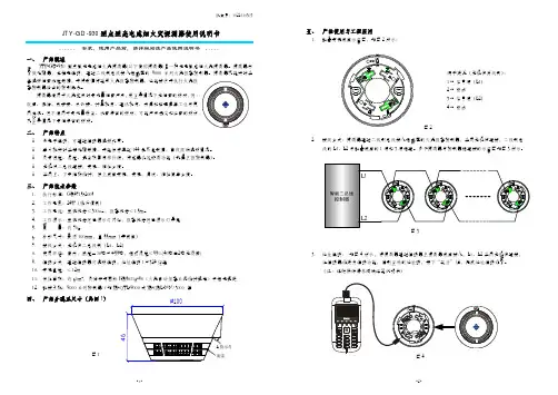
三、产品技术参数1.执行标准:GB4715-20052.工作电压:24V(脉冲调制)3.工作电流:监视状态<300uA,报警状态<1.5mA4.工作指示:监视状态红色指示灯闪烁,报警状态红色指示灯常亮5.重量:约70g6.外形尺寸:直径100mm,高55mm(带底座)7.接线方式:无极性二总线制(L1、L2)8.使用环境:室内,温度-10℃~+55℃,相对湿度≤95%(40℃±2℃无凝露)9.编码方式:通过编码器可现场编码,地址编码1~324任选10.安装高度:≤12m11.保护面积:约60m2,具体参考国标GB50116-98《火灾自动报警系统设计规范》中相关规定12.配接主机:9000系列控制器(如JB-QTL-9000或JB-QBL-MN/300)等四、产品外观及尺寸(见图1)图1五、产品使用与工程应用1.配套安装底座示意图,如图2所示:图2端子定义(无极性两线制):1 -- 信号端(L1)2 -- 空脚3 -- 信号端(L2)4 -- 空脚2.接线方式:探测器通过二线制总线接入相兼容的火灾报警控制器,采用无极性连接,二线制总线的L1、L2与配套底座的1端和3端相连。
安装、使用产品前,请阅读安装使用说明书JTY-GF-GST9711(Ex)点型光电感烟火灾探测器安装使用说明书(Ver.1.06,2018.03)一、注意事项1.产品仅应被安装在产品安装使用说明书所明示规定的使用环境,不适用于有腐蚀性物质的场所(包括使用磷化铝杀虫剂的烟草仓库)。
产品不可被安装在对设备有特殊认证要求的环境或场所(包括但不限于包括但不限于煤矿瓦斯、粉尘爆炸性环境、飞机、火车、机动车等交通工具)。
2.GST-LD-8332编址接口模块应安装在安全区域,本安侧和非本安侧接线应分开,并保持一定距离(至少50mm)。
3.安全栅接地必须可靠,连接螺钉必须拧紧,不可松动,接地电阻不能大于1Ω,本安回路最大分布参数不应超过规定值,即电缆间分布电容不得大于0.083 F,分布电感不得大于4.0mH。
4.经防爆检验合格的产品,维修时不能随意更换或改动影响防爆性能的元器件和结构。
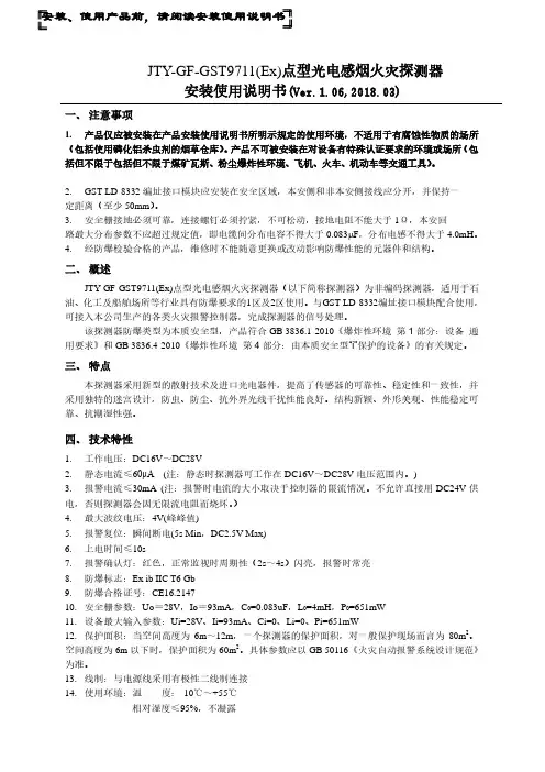
二、概述JTY-GF-GST9711(Ex)点型光电感烟火灾探测器(以下简称探测器)为非编码探测器,适用于石油、化工及船舶场所等行业具有防爆要求的1区及2区使用。
与GST-LD-8332编址接口模块配合使用,可接入本公司生产的各类火灾报警控制器,完成探测器的信号处理。
该探测器防爆类型为本质安全型,产品符合GB 3836.1-2010《爆炸性环境第1部分:设备通用要求》和GB 3836.4-2010《爆炸性环境第4部分:由本质安全型“i”保护的设备》的有关规定。
三、特点本探测器采用新型的散射技术及进口光电器件,提高了传感器的可靠性、稳定性和一致性,并采用独特的迷宫设计,防虫、防尘、抗外界光线干扰性能良好。
结构新颖、外形美观、性能稳定可靠、抗潮湿性强。
四、技术特性1.工作电压:DC16V~DC28V2.静态电流≤60μA(注:静态时探测器可工作在DC16V~DC28V电压范围内。
)3.报警电流≤30mA (注:报警时电流的大小取决于控制器的限流情况。
一、注意安装使用说明书(Ver.JTY-GM-GSTN9811(Ex)/WIS点型光电感烟火灾探测器1.01,2022.04)事项1. 产品仅应被安装在产品安装使用说明书所明示规定的使用环境,不适用于有腐蚀性物质的场所(包括使用磷化铝杀虫剂的烟草仓库)。
产品不可被安装在对设备有特殊认证要求的环境或场所(包括但不限于船舶、飞机、火车、机动车等交通工具)。
如有特殊需求,请联系本公司相应销售人员。
2. 应严格按照有关爆炸危险场所安全规定进行安装与维修。
3. 严禁在现场带电开盖。
4. 外壳应接地良好。
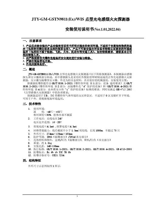
二、概述JTY-GM-GSTN9811(Ex)/WIS点型光电感烟火灾探测器(以下简称探测器),本探测器由感烟探头和安全栅两部分组成,其中感烟探头是采用红外散射原理研制而成的点型光电感烟火灾探测器,安全栅为隔爆型安全栅,外壳为铝合金材料,具有很好的机械强度,安装使用方便。
探测器防爆性能符合GB/T 3836.1-2021《爆炸性环境第1部分:设备通用要求》及GB/T 3836.2-2021《爆炸性环境第2部分:由隔爆外壳“d”保护的设备》和《GB/T 3836.4-2021 爆炸性环境第4部分:由本质安全性“i”保护的设备》标准的要求,同时还满足GB 4715-2005《点型感烟火灾探测器》中的各项要求。
探测器适用于ⅡB、ⅡC类爆炸性气体环境的1区和2区,不适用于0区及煤矿井下环境,可用于户外,需根据现场环境选用。
三、技术特性1.使用环境:温度:-40℃~+55℃相对湿度≤95%,腔体内部不凝露2.工作电压:总线电压24V电压允许范围:16~28V3.监视电流≤4.1mA ,报警电流≤4.3mA4.回路带载能力:线芯截面不小于1.5mm2双绞线,长度1000m,不超过70只5.外形尺寸:274mm×176mm×103mm6.防护等级:IP65(隔爆部分)/IP54(本安部分)7.壳体材料和颜色:金属/红色(隔爆部分);塑料/白色(本安部分)8.重量:约1.3kg9.安装孔距:149~156mm10.执行标准:GB/T 3836.1-2021、GB/T 3836.2-2021、GB/T 3836.4-2021、GB 4715-200511.防爆标志:Ex db ib IIC T6 Gb12.防爆合格证号:CE23.7254四、结构特征外形尺寸示意图如图1所示:图1 探测器外形示意图五、安装与布线警告:安装设备之前,请切断回路的电源。
•All installations should comply with local regulations•For detectors approved to UL268refer to NFPA72for installation guidance.In such installations,it is advised that the maximum distance of Detector and Reflector from the ceiling must be 10%of the distance between floor and ceiling•For installations covering less than 18m,the Short Range Mask must be used•Position beam as high as possible,but with a minimum distance of 0.5m from Detector and Reflector to ceiling.•Mount Detector and Reflector directly opposite each other•Do NOT position Detector where personnel or objects can enter the beam path •Do NOT position 2Detectors facing each other •Detector LED indicator must face downward•Do NOT install the Detector or Reflector in environments where condensation or icing are likely tooccur18—50m =150—100m =48—18m =1Use Short RangeMaskEnsure clear line ofsight from Detector to ReflectorMount on solid surfaces (structural wall or girder)1.General Information2.Fitting the ProductClip PCB intobaseInsert DetectorcableLED indicator must face downward3.Wiring DiagramsWiring two Detectors onto two Zones:To Detector 1To Detector 2EOL EOLDET 1DET 2N/OCOMN/CN/OCOMN/CN/OCOMN/CN/OCOMN/C14V -36V DC123123123Con C Zone 1-Zone 1+Zone 2+Zone 2-Supply +Ext Reset Supply -Con A Con B see note 1see note 1ExtReset123Con D •Note 1:This component is the fire resistor.Its value is specified by the Fire Control Panel manufacturer.For U.S.installations it is typically a short circuit •ALWAYS use a separate 2-core cable for each Detector head•CAUTION:For system monitoring -Do not use looped wire under any terminals.Break wire run to provide monitoring of connections •Components not supplied:•End Of Line ('EOL')component -supplied by Fire Control Panel manufacturer •Fire Resistor•After installation,check operation of Fire and Fault connection on Fire Panel•Apply a voltage of 5V to 40V to ‘Ext Reset’contact for at least 2seconds to clear a latched fire conditionFireFaultFire Fault3.Wiring Diagrams (continued)Relay connections for wiring the two Detectors of one Controller onto one Zone:For wiring to other types of Fire Control Panel,or to wire multiple Controllers onto one Zone,refer to additional installation instructions supplied with the productEOLN/O COM N/C N/O COM N/CN/OCOMN/CN/OCOMN/C123123123Con C Zone 1-Zone 1+Con A Con B see note 1123Con D Fire Fault FireFault5seconds5secondsNOTE:One System Controller can be used to control and monitor up to two Detector heads.The ‘#’symbol in this guide is used to represent the number of the Detector currently selected (1or 2).4.Apply power•Commissioned system:•Detectors have been found but the selected Detector is not aligned:•Detector is connected butnot ‘Found’(normal on uncommissionedsystem):•Communications fault,or no Detector connected:Pressfor Pass Codescreen:•Default PassCode:1234•Change digit •Move between digits •Accept•An incorrect Pass Code will return the display to the Pass Code entry screen•Three incorrect attempts will lock access for three minutes5.Enter Pass Code to Access Engineering Menu6.Find Detectors•Press to enable ‘Found’Detectors at any point during 60s countdown•Any unused Detector channels are switched off •Press to re-scan if number is incorrect•‘Find’is automatically displayed the first time this process is run.‘Find’can also be accessed in the System Controller settings menu.Find must be performed when adding or removing a detector to an already ‘Found’system.•In‘Hi A’mode(default),during normal operation the system will take5.5mA if one Detector is connected or8mA if two Detectors are connected. During Laser targeting,Auto, Hand and Home functions,the system will take36mA.•In‘Lo A’mode(selected via the System Controller settings menu),the system will take 5.5mA or8mA in ALL modes of operation.The Detector will move more slowly during Align, Laser targeting and Home,so it is recommended to leave the system set to‘Hi A’if the current isavailable.7.Select Power Mode8.Select Detector•Select Detector to be accessed•All Detectors need to be aligned separately•Steps9to129.Select Distance between Detector and Reflector •Select8-50m(default)or100m(Set for eachDetector)SER TargetingThe system will signal Fault while in this modeThe LASER is used to align the Detector with the Reflector.It is an approximate alignment tool only.After Auto-Align the LASERwill not necessarily be pointing on the Reflector •Use to move the LASER as close to the Reflector as possible •One press of an arrow key results in one movement of the Detector head •Press or to turn off the LASER and return to the Settings menu•Refer to Additional Detector Information for troubleshooting if LASER is not visible11.‘Auto’Alignment•Select ‘Auto’to automatically align the infrared beam •Signal Strength will be shown during Alignment•If the LASER is turned on it will not necessarily be pointing on the Reflector after ‘Auto’is run -this is normal•If ‘Auto’ends with an error code ‘E-’,refer to troubleshootingHiA:2minutes LoA:25minutes•When ‘Set’is displayed press whilst the Reflector is still uncovered•When ‘S-00’is displayed,cover the Reflector with a non-reflective material and leave covered,then press•When ‘S-01’is displayed,uncover the Reflector and leave uncovered,then press •Repeat Steps 8to 12for any other Detectors found during the ‘Find’process12.‘Set’0/100(Calibrate)13.System is Aligned•Green LED on Detector will flash every 10seconds,and Signal Strength should be between 99%and 101%•Default values:35%Fire Threshold,10second delay to Fire and Fault,Non-Latching mode14.Manual Fire and Fault TestsAfter installation or cleaning,it is recommended that a manual Fire and Fault test is performed:Fire Test:Cover the Reflector slowly so that it takes longer than 5seconds to cover.The System Controller will signal Fire to the Fire Control Panel after the delay to fire has expired (10s default)Fault Test:Cover the Reflector completely within 2seconds.The System Controller will signal Fault back to the Fire Control Panel after the delay to fault has expired (10s default)Detector Fire LED Test Detector will signal Fire,System Controller will stay Normal.Press to exitwithout performing the testRelay/Controller Wiring Test System Controller signals ‘Fire’to Fire Control Panel Press or to exitIt is possible to perform a Fire Test from the System Controller,to test the wiring to the Fire Control PanelNOTE:The Remote Fire Test is acceptable for Fire Authority Acceptance and Routine Maintenance per UL268-515.Remote Fire TestThis setting is the threshold at which the Detector will detect a fire Default factorysetting=35%(Set for each Detector)16.Fire ThresholdComplies with EN54-12for sensitivity levels between 25%and 35%with a maximum delay to fire of 20seconds•Sensitivity can be adjusted in 1%steps by pressing up or down keys •Press to accept setting EN Approved Sensitivity Ranges:to move between icons in theDetector Menu,shownDelay 1(Fire)These settings are the delays that the System Controller uses before signalling a FIRE or FAULT condition respectively to the Fire Control Panel.Default factory setting=10seconds Delay 2(Fault)In Latching Mode the system will stay in Fire condition after the fire clears.In Non-Latching Mode the system will automatically return to normal condition after the fire clears(Set for each Detector)17.Fire/Fault Delaytching/Non-Latching ModeTo clear a latched fire,apply 5-40V to the External Reset terminal,enter the passcode,or power cycle for 20s(Set for each Detector)19.Cleaning the SystemThe system will automatically compensate for dust build-up by changing the Compensation Level.However,it is recommended that the Detector lenses and the Reflector are cleaned periodically with a soft lint-free cloth.If the Compensation Level for a particular Detector remains above130for several days,this indicates that cleaning should take place on that Detector.The system should be isolated from the Fire Control Panel before cleaning takes place.After cleaning,verify that the system is operating normally:If the Signal Strength is between92%and108%-leave the system to compensate back to100%(this should take no more than12hours)If the Signal Strength is above108%-reduce Compensation Level until Signal Strength is92—108%,and wait for system to compensate back to100%If the Signal Strength is below92%-perform LASER Targeting,Auto-Align,and Set.How to change Compensation Level:20.Troubleshooting21.1.Multiple Zone WiringWhen using more than one System Controller on a single zone of a conventional Fire Control Panel (FCP),it is important to choose the correct method of wiring.Incorrect wiring may result in a Controller isolating subsequent devices on that zone if it enters a Fault condition,and may prevent these subsequent devices signalling a Fire condition back to the FCP .If the FCP monitors for point detector removal,it is possible to use the following wiring diagrams which use diodes to provide zone continuity in the event of a Fault state on any Controller.Two Detectors connected to Controller:Single Detector connected to Controller on “Det 1”:Note 1–This component is the Fire Resistor.Its value is specified by the FCP manufacturer,and is not supplied with the System Controller.For U.S.installations it is typically a short circuit.Note 2–Recommended diode type:Schottky,60Volt,1Amp;must be UL listed for installations meeting NFPA72.Con C Fire Con D FaultFire Con A Fault Con BCon C Fire Con D FaultFire Con A Fault Con B1.Multiple Zone Wiring(continued)If the FCP does not monitor for detector removal,it is recommended that the following wiring diagram be used.For installations conforming to UL268and NFPA72,the following diagram MUST be used when wiring multiple Controllers onto one zone.Note1–This component is the Fire Resistor.Its value is specified by the FCP manufacturer, and is not supplied with the System Controller.For U.S.installations it is typically a short circuit.EOL–End of Line component.This is supplied with the FCP,and not supplied with the System Controller.Do NOT wire to any unused relay pairs.Con A and Con B are the relay outputs for Detector1;Con C and Con D are the relay outputs for Detector2.2.Event LoggerThe System Controller contains a logging function which will store information for the most recent 50events on each Detector.For each Fire or Fault activation,the controller will store:If there have been power-cycle events on the controller,all timing information will be lost for those events that occurred prior to the most recent of the power-cycles.To erase and restart the event logger,press and hold ‘left’and ‘right’keys together when displaying any of the event log entries.Press ‘tick’when prompted by ‘SurE’.To access the event log,press tick on the Event Logger icon when the relevant detector is highlighted:Event Number01is the most recent event 02is the event before 0103is the event before 02,and so on•The event code –This is the same as the error code (E-__)that would be displayed during the Fault,or one of the following:•99-Log erased •98-Power cycle •97-Fire Detected•96-Remote Fire Test initiated •95-AUTO initiated •94-LASER activated •93-‘Home’initiated•The elapsed time since the event occurred •The duration of the event•The signal strength when the event occurred (if applicable)•The AGC value when the event occurred (if applicable)2.Event Logger(continued)Press left to access olderevents,and right to accessnewer events.When therelevant event is selected,press down to accessfurther information about theevent.Time elapsed since eventstarted.‘—‘will be displayedif the event occurred prior tothe most recent power cycle.Duration of event.‘—‘will bedisplayed if the event is stilloccurring,or if a power cycleoccurred while the eventwas in progress,or if thereis no duration associatedwith the event type(e.g.power-on)Signal strength when theevent occurred.If the signalstrength could not be readduring the event‘—‘will bedisplayed.AGC value when the eventoccurred.If the AGC valuecould not be read during theevent‘—‘will be displayed.3.Troubleshooting-LASER not visibleIf it is not possible to see the LASER because of the installation environment(for example,if you cannot see the Reflector from the System Controller or there is high ambient light)then use‘Hand’Alignment.This option displays the signal strength value returned by the Detector, and allows the user to move the beam1.Start‘Auto’Alignment and press after two seconds to exit.(this will maximise infrared power)2.Select‘Hand’alignmente to steer the beam until the signal strength is above800.There is no auto-repeat function on any key.To move the motor in any given direction more than once, press the key multiple times4.Cover the Reflector.If the Signal Strength does not drop by more than half,the beam is not aligned to the Reflector,so repeat Step35.Perform‘Auto’alignment,followed by‘Set’4.Troubleshooting-HOMEIf it is not known where the beam is pointing,use Home Position to automatically steer the infrared beam to approximately the centre of its range of movement.•Press or to exit this function•This will take up to3minutes to complete•When complete the display will return to the Engineering Menu5.Display and Indicators -LCD Icon LayoutD e g r e e s F i r e T r a n s m S i g n a l R e c e i v S i g n a l %/VS y s t e F i r e L A S E R S e t B a r G r a p hS y s t e m L o c k e d /U n l o c k e dW a r n i n gB u s yM e t r e s6.Display and Indicators -Detector and System ControllerStatus Indicators123•PressinthismenutoenterthePassCode•PresstoputthesystemintoSleep ControllerStatusSystemControllerSoftwareVersionDetectorSoftwareVersionDetectorStatus8—5mor5—1m8.Menu Layout -Engineering Menu•T h e P a s s C o d e m u s t b e e n t e r e d t o a c c e s s t h e E n g i n e e r i n g M e n u •T h e m e n u i s n a v i g a t e d b y u s i n g k e y s t o m o v e t h e c u r s o r .•I t e m s a r e s e l e c t e d b y u s i n g •P r e s s i n g e x i t s t h i s m e n u a n d r e t u r n s t h e s y s t e m t o a ‘l o c k e d ’s t a t eS e t t i n g s E v e n t L o g F i r e T e s t D e l a y9.**Gain**1% SetDetector10.System Controller SettingsCodePower Mode•Change Pass Code Use to access each digit Use to change the digit Press to save the new Pass Code and return to the settings menu Press to cancel the change and return to the Engineering menuDetectors。
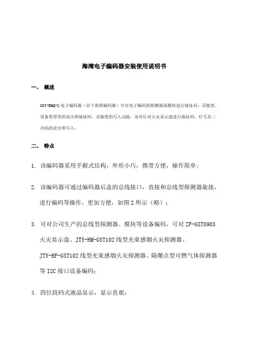
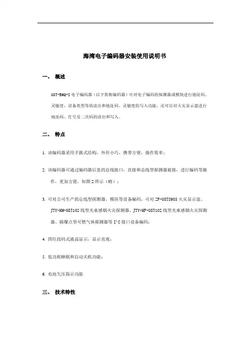
海湾电子编码器安装使用说明书一、概述GST-BMQ-2电子编码器(以下简称编码器)可对电子编码的探测器或模块进行地址码、灵敏度、设备类型等的读出和地址码、灵敏度的写入功能,还可以对火灾显示盘进行地址码、灯号及二次码的读出和写入。
二、特点1. 该编码器采用手握式结构,外形小巧,携带方便,操作简单;2. 该编码器可通过编码器后盖的总线接口,直接和总线型探测器旋接,进行编码等操作,更加方便,如图2所示(略);3. 可对公司生产的总线型探测器、模块等设备编码,可对ZF-GST8903火灾显示盘、JTY-HM-GST102线型光束感烟火灾探测器、JTY-HF-GST102线型光束感烟火灾探测器、隔爆点型可燃气体探测器等I2C接口设备编码;4. 四位段码式液晶显示,显示直观;5. 低功耗睡眠和自动关机功能;6. 电池欠压指示功能三、技术特性1. 电源:1节9V叠式电池2. 工作电流≤8mA3. 待机电流≤100чA4. 使用环境:温度:-10℃~+50℃相对湿度≤95%,不凝露5. 尺寸:164mm×64mm×37mm四、结构特征外形示意图如图1所示(略)1:电源开关 2:液晶屏3:总线插口 4:火灾显示盘接口(I2C)5:复位键 6:固定螺丝7:电池盒后盖 8:铭牌9:JTY-GD-G3、JTY-ZCD-G3N探测器总线接口10:JTY-GM-GST9611、JTW-ZOM-GST9612型探测器总线接口11:电池盒后盖螺丝 12:保护盖其中各部分名称和功能说明如下:1. 电源开关:完成系统硬件开机和关机操作。
2. 液晶屏:显示有关探测器的一切信息和操作人员输入的相关信息,并且当电源欠压时给出指示。
3. 总线插口:编码器通过总线插口与探测器或模块相连。
4. 火灾显示盘接口(I2C):编码器通过此接口与ZF-GST8903火灾显示盘或以I2C编程方式编码的探测器相连。
5. 复位键:当编码器由于长时间不使用而自动关机后,按下复位键可以使系统重新上电并进入工作状态。
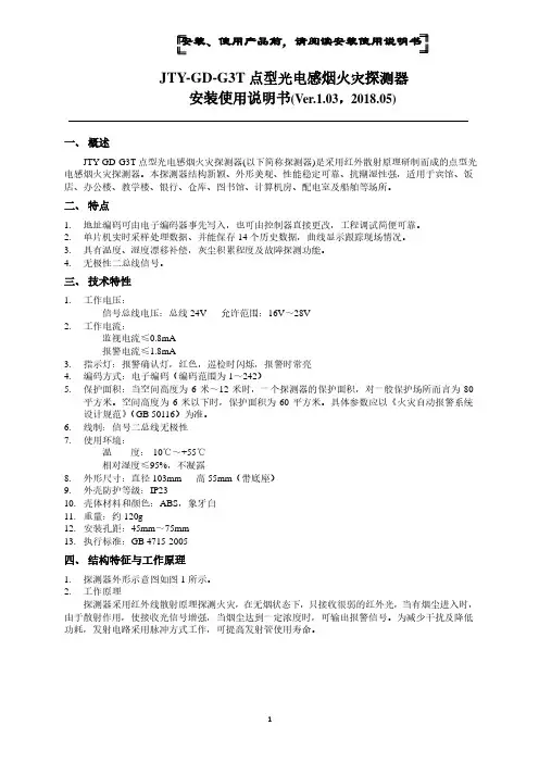
安装、使用产品前,请阅读安装使用说明书JTY-GD-G3T点型光电感烟火灾探测器安装使用说明书(Ver.1.03,2018.05)一、概述JTY-GD-G3T点型光电感烟火灾探测器(以下简称探测器)是采用红外散射原理研制而成的点型光电感烟火灾探测器。
本探测器结构新颖、外形美观、性能稳定可靠、抗潮湿性强,适用于宾馆、饭店、办公楼、教学楼、银行、仓库、图书馆、计算机房、配电室及船舶等场所。
二、特点1.地址编码可由电子编码器事先写入,也可由控制器直接更改,工程调试简便可靠。
2.单片机实时采样处理数据、并能保存14个历史数据,曲线显示跟踪现场情况。
3.具有温度、湿度漂移补偿,灰尘积累程度及故障探测功能。
4.无极性二总线信号。
三、技术特性1.工作电压:信号总线电压:总线24V 允许范围:16V~28V2.工作电流:监视电流≤0.8mA报警电流≤1.8mA3.指示灯:报警确认灯,红色,巡检时闪烁,报警时常亮4.编码方式:电子编码(编码范围为1~242)5.保护面积:当空间高度为6米~12米时,一个探测器的保护面积,对一般保护场所而言为80平方米。
空间高度为6米以下时,保护面积为60平方米。
具体参数应以《火灾自动报警系统设计规范》(GB 50116)为准。
6.线制:信号二总线无极性7.使用环境:温度:-10℃~+55℃相对湿度≤95%,不凝露8.外形尺寸:直径103mm 高55mm(带底座)9.外壳防护等级:IP2310.壳体材料和颜色:ABS,象牙白11.重量:约120g12.安装孔距:45mm~75mm13.执行标准:GB 4715-2005四、结构特征与工作原理1.探测器外形示意图如图1所示。
2.工作原理探测器采用红外线散射原理探测火灾,在无烟状态下,只接收很弱的红外光,当有烟尘进入时,由于散射作用,使接收光信号增强,当烟尘达到一定浓度时,可输出报警信号。
为减少干扰及降低功耗,发射电路采用脉冲方式工作,可提高发射管使用寿命。

海湾电子编码器安装使用说明书一、概述GST-BMQ-2电子编码器(以下简称编码器)可对电子编码的探测器或模块进行地址码、灵敏度、设备类型等的读出和地址码、灵敏度的写入功能,还可以对火灾显示盘进行地址码、灯号及二次码的读出和写入。
二、特点1. 该编码器采用手握式结构,外形小巧,携带方便,操作简单;2. 该编码器可通过编码器后盖的总线接口,直接和总线型探测器旋接,进行编码等操作,更加方便,如图2所示(略);3. 可对公司生产的总线型探测器、模块等设备编码,可对ZF-GST8903火灾显示盘、JTY-HM-GST102线型光束感烟火灾探测器、JTY-HF-GST102线型光束感烟火灾探测器、隔爆点型可燃气体探测器等I²C接口设备编码;4. 四位段码式液晶显示,显示直观;5. 低功耗睡眠和自动关机功能;6. 电池欠压指示功能三、技术特性1. 电源:1节9V叠式电池2. 工作电流≤8mA3. 待机电流≤100чA4. 使用环境:温度:-10℃~+50℃相对湿度≤95%,不凝露5. 尺寸:164mm×64mm×37mm四、结构特征外形示意图如图1所示(略)1:电源开关 2:液晶屏3:总线插口 4:火灾显示盘接口(I²C)5:复位键 6:固定螺丝7:电池盒后盖 8:铭牌9:JTY-GD-G3、JTY-ZCD-G3N探测器总线接口10:JTY-GM-GST9611、JTW-ZOM-GST9612型探测器总线接口11:电池盒后盖螺丝 12:保护盖其中各部分名称和功能说明如下:1. 电源开关:完成系统硬件开机和关机操作。
2. 液晶屏:显示有关探测器的一切信息和操作人员输入的相关信息,并且当电源欠压时给出指示。
3. 总线插口:编码器通过总线插口与探测器或模块相连。
4. 火灾显示盘接口(I²C):编码器通过此接口与ZF-GST8903火灾显示盘或以I²C编程方式编码的探测器相连。
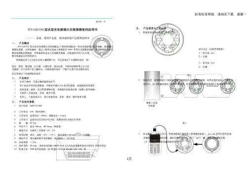
版本号:18JTY-GD-930 型点型光电感烟火灾探测器使用说明书五、产品使用与工程应用1. 配套安装底座示意图,如图2 所示:- - - - - - 安装、使用产品前,请详细阅读产品使用说明书- - - - -一、产品概述JTY-GD-930 型点型光电感烟火灾探测器(以下简称探测器)是一种光电型感烟火灾探测器。
探测器内置微处理器,支持电编码,通过二线制总线接入相兼容的9000 系列火灾报警控制器。
探测器既能实时采集现场烟雾浓度数据,并将数据传送至火灾报警控制器,也能接收并执行火灾报警控制器给出的控制命令。
端子定义(无极性两线制):1 -- 信号端(L1)2 -- 空脚探测器适用于火灾发生时有大量烟雾产生,而正常情况下无烟雾的场所,例:3 -- 信号端(L2)饭店、旅馆、教学楼、办公楼、计算机房、通讯机房、书库和档案库等工业与民4 -- 空脚用建筑。
但不适用于有大量粉尘、水雾滞留的场所,可能产生蒸汽和油雾的场所及正常情况下有烟滞留的场所。
图2二、产品特点✓全电子编码,可通过编码器现场改写。
✓单片机实时采样处理数据、并能保存最近144 条历史数据,曲线跟踪现场情况。
2. 接线方式:探测器通过二线制总线接入相兼容的火灾报警控制器,采用无极性连接,二线制总线的L1、L2 与配套底座的1 端和3 端相连。
多个探测器与控制器相连接的示意图如图3 所示。
✓具有温度、湿度、灰尘积累漂移补偿,传感器失效检测功能(故障上报控制器)。
✓无极性二总线连接,安装、维护方便。
✓采用上、下盖结构设计,独立底座安装,安装、调试、维护简单方便。
三、产品技术参数1. 执行标准:GB4715-2005 智能二总线控制器2. 工作电压:24V(脉冲调制)3. 工作电流:监视状态<300uA,报警状态<1.5mA4. 工作指示:监视状态红色指示灯闪烁,报警状态红色指示灯常亮5. 重量:约70g 图36. 外形尺寸:直径100mm,高55mm(带底座)7. 接线方式:无极性二总线制(L1、L2)3. 地址编码:如图4 所示,将探测器通过编码器上探测器底座接入,L1、L2 采用无极性连接,8. 使用环境:室内,温度-10℃~+55℃,相对湿度≤95%(40℃±2℃无凝露)把编码器设定为编码功能,编制正确的地址码,按下“运行”键,完成地址编码设置。

JTY-GD-G3型点型光电感烟火灾探测器作业指引书
一、作业目旳:协助班组理解掌握GTY-GD-G3型点型光电感烟探测器旳工作原理,以及在线故障时旳检查与解决,对存在旳危险进行分析,增强自身防护意识。
二、合用范畴:GTY-GD-G3型点型光电感烟探测器
三、采用原则:
四、工作原理:
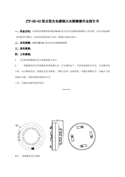
1.工作原理探测器外形示意图如图1所示。
2.探测器采用红外线散射原理探测火灾,在无烟状态下,只接受很弱旳红外光,当有烟尘进入时,由于散射作用,使接受光信号增强,当烟尘达到一定浓度时,可输出报警信号。
为减少干扰及减少功耗,发射电路采用脉冲方式
工作,可提高发射管使用寿命。
五、作业环节、危险分析、安全措施:
控制器报警时,一方面立即赶赴主控室,观测、询问故障现象,掌握第一手材料,其环节如下:
六、标定措施及接线:
1. LB491标定措施
基本设立(如日期/时间、测量模式、放射源以及测量管径等)完毕后,可以进行标定过程。
有两种标定措施可以选择:单点标定、两点/多点标定。
当现场只需要一种测量点用。
海湾电子编码器安装使用说明书一、概述GST-BMQ-2电子编码器(以下简称编码器)可对电子编码的探测器或模块进行地址码、灵敏度、设备类型等的读出和地址码、灵敏度的写入功能,还可以对火灾显示盘进行地址码、灯号及二次码的读出和写入。
二、特点1. 该编码器采用手握式结构,外形小巧,携带方便,操作简单;2. 该编码器可通过编码器后盖的总线接口,直接和总线型探测器旋接,进行编码等操作,更加方便,如图2所示(略);3. 可对公司生产的总线型探测器、模块等设备编码,可对ZF-GST8903火灾显示盘、JTY-HM-GST102线型光束感烟火灾探测器、JTY-HF-GST102线型光束感烟火灾探测器、隔爆点型可燃气体探测器等I2C接口设备编码;4. 四位段码式液晶显示,显示直观;5. 低功耗睡眠和自动关机功能;6. 电池欠压指示功能三、技术特性1. 电源:1节9V叠式电池2. 工作电流≤8mA3. 待机电流≤100чA4. 使用环境:温度:-10℃~+50℃相对湿度≤95%,不凝露5. 尺寸:164mm×64mm×37mm四、结构特征外形示意图如图1所示(略)1:电源开关 2:液晶屏3:总线插口 4:火灾显示盘接口(I2C)5:复位键 6:固定螺丝7:电池盒后盖 8:铭牌9:JTY-GD-G3、JTY-ZCD-G3N探测器总线接口10:JTY-GM-GST9611、JTW-ZOM-GST9612型探测器总线接口11:电池盒后盖螺丝 12:保护盖其中各部分名称和功能说明如下:1. 电源开关:完成系统硬件开机和关机操作。
2. 液晶屏:显示有关探测器的一切信息和操作人员输入的相关信息,并且当电源欠压时给出指示。
3. 总线插口:编码器通过总线插口与探测器或模块相连。
4. 火灾显示盘接口(I2C):编码器通过此接口与ZF-GST8903火灾显示盘或以I2C编程方式编码的探测器相连。
5. 复位键:当编码器由于长时间不使用而自动关机后,按下复位键可以使系统重新上电并进入工作状态。
海湾电子编码器安装使用说明书一、概述GST-BMQ-2电子编码器(以下简称编码器)可对电子编码的探测器或模块进行地址码、灵敏度、设备类型等的读出和地址码、灵敏度的写入功能,还可以对火灾显示盘进行地址码、灯号及二次码的读出和写入。
二、特点1. 该编码器采用手握式结构,外形小巧,携带方便,操作简单;2. 该编码器可通过编码器后盖的总线接口,直接和总线型探测器旋接,进行编码等操作,更加方便,如图2所示(略);3. 可对公司生产的总线型探测器、模块等设备编码,可对ZF-GST8903火灾显示盘、JTY-H M-GST102线型光束感烟火灾探测器、JTY-HF-GST102线型光束感烟火灾探测器、隔爆点型可燃气体探测器等I²C接口设备编码;4. 四位段码式液晶显示,显示直观;5. 低功耗睡眠和自动关机功能;6. 电池欠压指示功能三、技术特性1. 电源:1节9V叠式电池2. 工作电流≤8mA3. 待机电流≤100чA4. 使用环境:温度:-10℃~+50℃相对湿度≤95%,不凝露5. 尺寸:164mm×64mm×37mm四、结构特征外形示意图如图1所示(略)1:电源开关 2:液晶屏3:总线插口 4:火灾显示盘接口(I²C)5:复位键 6:固定螺丝7:电池盒后盖 8:铭牌9:JTY-GD-G3、JTY-ZCD-G3N探测器总线接口10:JTY-GM-GST9611、JTW-ZOM-GST9612型探测器总线接口11:电池盒后盖螺丝 12:保护盖其中各部分名称和功能说明如下:1. 电源开关:完成系统硬件开机和关机操作。
2. 液晶屏:显示有关探测器的一切信息和操作人员输入的相关信息,并且当电源欠压时给出指示。
3. 总线插口:编码器通过总线插口与探测器或模块相连。
4. 火灾显示盘接口(I²C):编码器通过此接口与ZF-GST8903火灾显示盘或以I²C编程方式编码的探测器相连。
点型光电感烟火灾探测器JTY-GD-G3点型光电感烟火灾探测器•一、JTY-GD-G3特点JTY-GD-G3型点型光电感烟火灾探测器采用无极性信号二总线技术,可与海湾公司生产的各类火灾报警控制器配合使用。
本探测器主要具有以下特点:(1)内置带A/D转换的八位单片计算机,具备强大的分析、判断能力,通过在探测器内部固化的运算程序,可自动完成对外界环境参数变化的补偿及火警、故障的判断,存储环境参数变化的特征曲线,极大提高了整个系统探测火灾的实时性、准确性;(2)采用电子编码方式,现场编码简单、方便;(3)采用指示灯闪烁的方式提示其正常工作状态,可在现场观察其运行状况;(4)底部采用密封方式,可有效防水、防尘、防止恶劣的应用环境对探测器造成的损坏;(5)专利产品,专利号为ZL99311724.4。
二、JTY-GD-G3主要技术指标(1)工作电压:总线24V(2)监视电流≤0.6mA(3)报警电流≤1.8mA(4)报警确认灯:红色,巡检时闪烁,报警时常亮(5)使用环境:温度:-10℃~+55℃相对湿度≤95%,不结露(6)编码方式:十进制电子编码(7)外壳防护等级:IP23(8)外形尺寸:直径:100mm,高:56mm(带底座)三、JTY-GD-G3保护面积当空间高度为6m~12m时,一个探测器的保护面积,对一般保护场所而言为80m2。
空间高度为6m以下时,保护面积为60m2。
具体参数应以《火灾自动报警系统设计规范》(GB50116)为准。
四、JTY-GD-G3结构特征、安装与布线探测器的外形结构示意图如图1-1:探测器安装方式如图1-2:接线盒可采用86H50型标准预埋盒,其结构尺寸外形示意图如图1-3:DZ-02探测器通用底座外形示意图如图1-4:底座上有4个导体片,片上带接线端子,底座上不设定位卡,便于调整探测器报警指示灯的方向。
预埋管内的探测器总线分别接在任意对角的二个接线端子上(不分极性),另一对导体片用来辅助固定探测器。