本科毕业设计桥梁外文翻译
- 格式:doc
- 大小:1.20 MB
- 文档页数:18
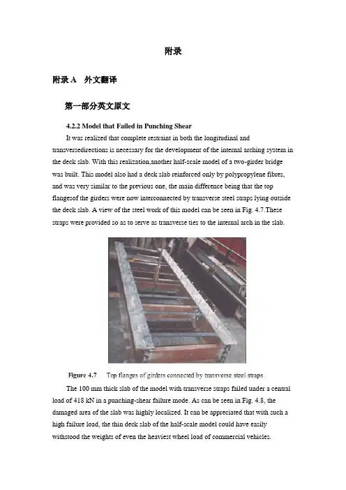
附录附录A 外文翻译第一部分英文原文4.2.2 Model that Failed in Punching ShearIt was realized that complete restraint in both the longitudinal and transversedirections is necessary for the development of the internal arching system in the deck slab. With this realization,another half-scale model of a two-girder bridge was built. This model also had a deck slab reinforced only by polypropylene fibres, and was very similar to the previous one, the main difference being that the top flangesof the girders were now interconnected by transverse steel straps lying outside the deck slab. A view of the steel work of this model can be seen in Fig. 4.7.These straps were provided so as to serve as transverse ties to the internal arch in the slab.The 100 mm thick slab of the model with transverse straps failed under a central load of 418 kN in a punching-shear failure mode. As can be seen in Fig. 4.8, the damaged area of the slab was highly localized. It can be appreciated that with such a high failure load, the thin deck slab of the half-scale model could have easily withstood the weights of even the heaviest wheel load of commercial vehicles.The model tests described above and in sub-section 4.2.1 clearly demonstrate that an internal arching action will indeed develop in a deck slab, but only if it is suitably restrained.4.2.3 Edge StiffeningA further appreciation of the deck slab arching action is provided by tests on a scale model of a skew slab-on-girder bridge. As will be discussed in sub-section 4.4.2, one transverse free edge of the deck slab of this model was stiffened by a composite steel channel with its web in the vertical plane. The other free edge was stiffened by a steel channel diaphragm with its web horizontal and connected to the deck slab through shear connectors. The deck slab near the former transverse edge failed in a mode that was a hybrid between punching shear and flexure. Tests near the composite diaphragm led to failure at a much higher load in punching shear (Bakht and Agarwal, 1993).The above tests confirmed yet again that the presence of the internal arching action in deck slabs induces high in-plane force effects which in turn demand stiffer restraint in the plane of the deck than in the out-of-plane direction.4.3 INTERNALLY RESTRAINED DECK SLABSDeck slabs which require embedded reinforcement for strength will now be referred to as internally restrained deck slabs. The state-of-art up to 1986 relating to the quantification and utilization of the beneficial internal arching action in deck slabs with steel reinforcement has been provided by Bakht and Markovic (1986). Their conclusions complemented with up-to-date information are presented in this chapter in a generally chronological order which, however, cannot be adhered to rigidlybecause of the simultaneous occurrence of some developments.4.3.1 Static Tests on Scale ModelsAbout three decades ago, the Structures Research Office of the Ministry of Transportation of Ontario (MTO), Canada, sponsored an extensive laboratory-based research program into the load carrying capacity of deck slabs; this research program was carried out at Queen's University, Kingston, Ontario. Most of this research was conducted through static tests on scale models of slab-on-girder bridges. This pioneering work is reported by Hewitt and Batchelor (1975) and later by Batchelor et al. (1985), and is summarized in the following.The inability of the concrete to sustain tensile strains, which leads to cracking, has been shown to be the main attribute which causes the compressive membrane forces to develop. This phenomenon is illustrated in Fig. 4.9 (a) which shows the part cross-section of slab-on-girder bridge under the action of a concentrated load.The cracking of the concrete, as shown in the figure, results in a net compressive force near the bottom face of the slab at each of the two girder locations. Midway between the girders, the net compressive force moves towards the top of the slab. It can be readily visualized that the transition of the net compressive force from near the top in the middle region, to near the bottom at the supports corresponds to the familiar arching action. Because of this internal arching action, the failure mode of a deck slab under a concentrated load becomes that of punching shear.If the material of the deck slab has the same stress-strain characteristics in both tension and compression, the slab will not crack and, as shown in Fig. 4.9 (b), will not develop the net compressive force and hence the arching action.In the punching shear type of failure, a frustum separates from the rest of the slab, as shown in schematically in Fig. 4.10. It is noted that in most failure tests, the diameter of the lower end of the frustrum extends to the vicinity of the girders.From analytical and confirmatory laboratory studies, it was established that the most significant factor influencing the failure load of a concrete deck slab is the confinement of the panel under consideration. It was concluded that this confinement is provided by the expanse of the slab beyond the loaded area; its degree was founddifficult to assess analytically. A restraint factor, η, was used as an empirical measure of the confinement; its value is equal to zero for the case of no confinement and 1.0 for full confinement.The effect of various parameters on the failure load can be seen in Table 4.1, which lists the theoretical failure loads for various cases. It can be seen that an increase of the restraint factor from 0.0 to 0.5 results in a very large increase in the failure load. The table also emphasizes the fact that neglect of the restraint factor causes a gross underestimation of the failure load.It was concluded that design for flexure leads to the inclusion of large amounts of unnecessary steel reinforcement in the deck slabs, and that even the minimum amount of steel required for crack control against volumetric changes in concrete is adequate to sustain modern-day, and even future, highway vehicles of North America.It was recommended that for new construction, the reinforcement in a deck slab should be in two layers, with each layer consisting of an orthogonal mesh having the same area of reinforcement in each direction. The area of steel reinforcement in each direction of a mesh was suggested to be 0.2% of the effective area of cross-section of the slab. This empirical method of design was recommended for deck slabs with certain constraints.4.3.2 Pulsating Load Tests on Scale ModelsTo study the fatigue strength of deck slabs with reduced reinforcement, five small scale models with different reinforcement ratios in different panels were tested at the Queen's University at Kingston. Details of this study are reported by Batchelor et al. (1978).Experimental investigation confirmed that for loads normally encountered in North America deck slabs with both conventional and recommended reducedreinforcement have large reserve strengths against failure by fatigue. It was confirmed that the reinforcement in the deck slab should be as noted in sub-section 4.3.1. It is recalled that the 0.2% reinforcement requires that the deck slab must have a minimum restraint factor of 0.5.The work of Okada, et al. (1978) also deals with fatigue tests on full scale models of deck slabs and segments of severely cracked slab removed from eight to ten year old bridges. The application of these test results to deck slabs of actual bridges is open to question because test specimens were removed from the original structures in such a way that they did not retain the confinement necessary for the development of the arching action.4.3.3 Field TestingAlong with the studies described in the preceding sub-section, a program of field testing of the deck slabs of in-service bridges was undertaken by the Structures Research Office of the MTO. The testing consisted of subjecting deck slabs to single concentrated loads, simulating wheel loads, and monitoring the load-deflection characteristics of the slab. The testing is reported by Csagoly et al. (1978) and details of the testing equipment are given by Bakht and Csagoly (1979).Values of the restraint factor, η, were back-calculated from measured deflections.A summary of test results, given in Table 4.2, shows that the average value of η in composite bridges is greater than 0.75, while that for non-composite bridges is 0.42. It was concluded that for new construction, the restraint factor, η, can be assumed to have a minimum value of 0.5.Bakht (1981) reports that after the first application of a test load of high magnitude on deck slabs of existing bridges, a small residual deflection was observed in most cases. Subsequent applications of the same load did not result in further residual deflections. It is postulated that the residual deflections are caused by cracking of the concrete which, as discussed earlier, accompanies the development of the internal arching action. The residual deflections after the first cycle of loading suggest that either the slab was never subjected to loads high enough to cause cracking, or the cracks have 'healed' with time.第二部分汉语翻译4.2.2 在冲切剪应力下的实效模型我们已经知道在桥面板内部拱形系统的形成中,不仅纵向而且横向也被完全约束限制是完全必要的。

本科毕业设计外文翻译混凝土桥梁的结构形式院(系、部)名称:专业名称:学生姓名:学生学号:指导教师:The Structure of Concrete BridgePre-stressed concrete has proved to be technically advantageous, economically competitive, and esthetically superior bridges, from very short span structures using standard components to cable-stayed girders and continuous box girders with clear spans of nearly 100aft .Nearly all concrete bridges, even those of relatively short span, are now pre-stressed. Pre-casting, cast-in-place construction, or a combination of the two methods may be used .Both pre-tensioning and post tensioning are employed, often on the same project.In the United States, highway bridges generally must-meet loading ,design ,and construction requirements of the AASHTO Specification .Design requirements for pedestrian crossings and bridges serving other purposes may be established by local or regional codes and specifications .ACI Code provisions are often incorporated by reference .Bridges spans to about 100ft often consist of pre-cast integral-deck units ,which offer low initial cost ,minimum ,maintenance ,and fast easy construction ,with minimum traffic interruption .Such girders are generally pre-tensioned .The units are placed side by side ,and are often post-tensioned laterally at intermediate diaphragm locations ,after which shear keys between adjacent units are filled with non-shrinking mortar .For highway spans ,an asphalt wearing surface may be applied directly to the top of the pre-cast concrete .In some cases ,a cast-in-place slab is placed to provide composite action .The voided slabs are commonly available in depths from 15 to 21 in .and widths of 3 to 4 ft .For a standard highway HS20 loading, they are suitable for spans to about 50 ft, Standard channel sections are available in depths from 21 to 35 in a variety of widths, and are used for spans between about 20 and 60 ft .The hollow box beams-and single-tee girders are intended for longer spans up to about 100 ft.For medium-span highway bridges ,to about 120 ft ,AASHTO standard I beams are generally used .They are intended for use with a composite cast-in-place roadway slab .Such girders often combine pre-tensioning of the pre-cast member with post-tensioning of the composite beam after the deck is placed .In an effort to obtain improved economy ,some states have adopted more refined designs ,such as the State of Washington standard girders.The specially designed pre-cast girders may be used to carry a monorail transit system .The finished guide way of Walt Disney World Monorail features a series of segments, each consisting of six simply supported pre-tensioned beams ,together to from a continuous structure .Typical spans are 100 to 110 ft . Approximately half of the 337 beams used have some combination of vertical and horizontal curvatures and variable super elevation .Allbeams are hollow, a feature achieved by inserting a styro-foam void in the curved beams and by a moving mandrel in straight beam production.Pre-cast girders may not be used for spans much in excess of 120 ft because of the problems of transporting and erecting large, heavy units.On the other hand ,there is a clear trend toward the use of longer spans for bridges .For elevated urban expressways ,long spans facilitate access and minimize obstruction to activities below .Concern for environmental damage has led to the choice of long spans for continuous viaducts . For river crossings, intermediate piers may be impossible because of requirements of navigational clearance.In typical construction of this type, piers are cast-in-place, often using the slip-forming technique .A “hammerhead” section of box girder is often cast at the top of the pier, and construction proceeds in each direction by the balanced cantilever method. Finally, after the closing cast-in-place joint is made at mid-span, the structure is further post-tensioned for full continuity .Shear keys may be used on the vertical faces between segments, and pre-cast are glued with epoxy resin.The imaginative engineering demonstrated by many special techniques has extended the range of concrete construction for bridges far beyond anything that could be conceived just a few years ago .In the United States, twin curved cast-in –place segmental box girders have recently been completed for of span of 310 ft over the Eel River in northern California .Preliminary design has been completed for twin continuous box girders consisting of central 550 ft spans flanked by 390 ft side spans.Another form of pre-stressed concrete bridge well suited to long spans is the cable-stayed box girder .A notable example is the Chaco-Corrientes Bridge in Argentina .The bridges main span of 804 ft is supported by two A-frame towers, with cable stays stretching from tower tops to points along the deck .The deck itself consists of two parallel box girders made of pre-cast sections erected using the cantilever method .The tensioned cables not only provide a vertical reaction component to support the deck ,but also introduce horizontal compression to the box girders ,adding to the post-tensioning force in those members .Stress-ribbon Bridge pioneered many years ago by the German engineer Ulrich Finsterwalder. The stress-ribbon bridge carries a pipeline and pedestrians over the Rhine River with a span of 446 ft .The superstructure erection sequence was to (a) erect two pairs of cables, (b) place pre-cast slabs forming a sidewalk deck and a U under each of the sets of cables, and (c) cast-in-place concrete within the two Us. The pipeline is placed atop supports at railing height, off to one side, which greatly increases the wind speed of the structure.It is appropriate in discussing bridge forms to mention structural esthetics .The time ispast when structures could be designed on the basis of minimum cost and technical advantages alone .Bridge structures in particular are exposed for all to see .To produce a structure that is visually offensive ,as has occurred all too often in the past, is an act professional irresponsibility .Particularly for major spans ,but also for more ordinary structures ,architectural advice should be sought early in conceptual stage of the design process.混凝土梁桥的结构形式事实证明,预应力混凝土结构是在技术上先进、经济上有竞争力、符合审美学的一种先进技术。
Review of assessment and repair of fire-damaged RChighway bridgesAbstract:This paper presents a review of the progress of the research and engineering practice of assessment and repair of fire-damaged RC highway bridges,based on which existing and pressing problems of the evaluation method are pointed out.At last,Prospect for the development of assessment and repair of fire-damaged highway bridges is also proposed.Key words:fire damage;assessment;repair techniques;RC structure;bridge 1 PrefaceFires can cause great structural damage to bridges and major disruption to highway operations.These incidents stem primarily from vehicle accident (often oil tanker) fires,bridges might also be damaged by fires in adjacent facilities and from other causes.Quite a few of them,though rarely happened,lead to severe structural damage or collapse and casualty.On June 2,2008,fire disaster broke out under the 18th span of Nanjing Yangtze River Bridge and lasted for approximate 75min.During the fire’s development and extinguishment,the structure experienced the sharp rise and fall in temperature causing severe damage to fire- stricken segments.On April 29,2007,a gasoline tanker overturned on the connector from Interstate 8O to Interstate 880 in California.The intense heat from the subsequent fuel spill and fire weakened the stee1 underbelly of the elevated roadway ,collapsing approximately 165 feet of this elevated roadway onto a section of I—880below.On March 25,2004,Connecticut,United States,a tanker truck carrying fuel swerved to avoid a car and overturned,dumping 8000 gallons of home heating oil onto the Howard Avenue overpass.The consequent towering inferno melted the bridge structure and caused the southbound lanes to sag several feetUndocumented number of bridge fires occurring throughout the world each year cause varying degrees of disruption,repair actions,and maintenance cost.Althoughfires caused damage to the bridge structures ,some bridges continue to function after proper repair and retrofit.Still in some situations they have to be repaired for the cause of traffic pressure even though supposed to be dismantled and reconstructed.However ,in other cases,structures are severely damaged in the fire disaster and fail to function even after repair,or the costs of repair and retrofit overweigh their reconstruction costs overwhelmingly even if they are repairable,under which situation reconstruction serves as a preferable option.Therefore in—situ investigation and necessary tests and analyses should be conducted to make comprehensive assessment of the residual mechanical properties and working statuses after fire and to evaluate the degrees of damage of members and structures , in reference to which decisions are made to determine whether Fire damaged structures should be repaired or dismantled and reconstructed.Urgent need from engineering practice highlighted the necessity to understand the susceptibility and severity of these incidents as wel1 as to review available information on mitigation strategies,damage assessments,and repair techniques.2 Progress in Research and Engineering Practice2.1 Processes of Assessment and Repair of Fire damaged BridgeStructureIn China and most countries in the world,most highway bridges are built in RC structure.And the practice of the assessment and repair techniques of bridge structure after fire directly refer to that of RC structure,which,to date,domestic and foreign scholars have made great amount of research on,with their theories and practices being increasingly mature .As for the assessment and repair of fire-damaged reinforced concrete structures,there are two mainstream assessment processes in world.Countries including United States,United Kingdom and Japan adopt the assessment process stipulated by The British Concrete Society .This process grates the severity of fire damage of concrete structure into four degrees according to thedeflection,damage depth,cracking width, color,and loading capacity variation of fire-damaged structures and adopt four corresponding strategies (including demolish,strengthen after safety measures,strengthen. and strengthen in damaged segments) to deal with them accordingly.In general,this process is a qualitative method and considered,however,not quantity enough.In Chinese Mainland and Taiwan ,the prevailing as assessment and repair process of fire damaged incorporates following steps:In comparison this process is more detailed.(1)Conduct In-situ inspections,measurements,and tests including color observation,concrete observation,degree of rebar exposure observation,cracking measurement,deflection measurement,various destructive and nondestructive test methods as grounds for assessment of fire—damaged structures.In assessment of the post -fire mechanical properties of fire—damaged structures,historical highest temperature and temperature distribution of structure during the fire serve as decisive factors.The common methods to determine them incorporate petrographic analysis,ultrasonic method,Rebound method,Ignition Loss method,core test,and color observation method(2)calculate to determine whether the fire-damaged structure can meet the demand of strength and deflection under working loads after fire using mechanical properties of rebar and concrete before and after fire based on the historical highest and temperature distribution of structures obtained from step one.There are two main methods to evaluate the post -fire performance of fire-damaged structures:FEM method and Revised Classic Method.(3)On the basis of test and calculation results obtained from step two,take corresponding repair strategies and particular methods to strengthen the fire-damaged structures.2.2 Repair TechniquesFor the repair of fire—damaged bridge,proper repair methods should be taken according to the degr ee and range of the structure’s damage.Meanwhile the safetyand economy of the repair methods should be concerned with by avoiding destructing the original structure,preserving the valuable structural members,and minimizing unnecessary demolishment and reconstruction。

西南交通大学本科毕业设计(论文)外文资料翻译年级:学号:姓名:专业:指导老师:2013年 6 月外文资料原文:13Box girders13.1 GeneralThe box girder is the most flexible bridge deck form。
It can cover a range of spans from25 m up to the largest non—suspended concrete decks built, of the order of 300 m。
Single box girders may also carry decks up to 30 m wide。
For the longer span beams, beyond about 50 m,they are practically the only feasible deck section. For the shorter spans they are in competition with most of the other deck types discussed in this book.The advantages of the box form are principally its high structural efficiency (5.4),which minimises the prestress force required to resist a given bending moment,and its great torsional strength with the capacity this gives to re—centre eccentric live loads,minimising the prestress required to carry them。
The box form lends itself to many of the highly productive methods of bridge construction that have been progressively refined over the last 50 years,such as precast segmental construction with or without epoxy resin in the joints,balanced cantilever erection either cast in—situ or coupled with precast segmental construction, and incremental launching (Chapter 15)。
(Shear wall st ructural design ofh igh-lev el fr ameworkWu Jiche ngAbstract : In t his pape r the basic c oncepts of man pow er from th e fra me sh ear w all str uc ture, analy sis of the struct ur al des ign of th e c ont ent of t he fr ame she ar wall, in cludi ng the seism ic wa ll she ar spa本科毕业设计外文文献翻译学校代码: 10128学 号:题 目:Shear wall structural design of high-level framework 学生姓名: 学 院:土木工程学院 系 别:建筑工程系 专 业:土木工程专业(建筑工程方向) 班 级:土木08-(5)班 指导教师: (副教授)nratiodesign, and a concretestructure in themost co mmonly usedframe shear wallstructurethedesign of p oints to note.Keywords: concrete; frameshearwall structure;high-risebuildingsThe wall is amodern high-rise buildings is an impo rtant buildingcontent, the size of theframe shear wall must comply with building regulations. The principle is that the largersizebut the thicknessmust besmaller geometric featuresshouldbe presented to the plate,the force is close to cylindrical.The wall shear wa ll structure is a flatcomponent. Itsexposure to the force along the plane level of therole ofshear and moment, must also take intoaccountthe vertical pressure.Operate under thecombined action ofbending moments and axial force andshear forcebythe cantilever deep beam under the action of the force levelto loo kinto the bottom mounted on the basis of. Shearwall isdividedinto a whole walland theassociated shear wall in theactual project,a wholewallfor exampl e, such as generalhousingconstruction in the gableor fish bone structure filmwalls and small openingswall.Coupled Shear walls are connected bythecoupling beam shear wall.Butbecause thegeneralcoupling beamstiffness is less thanthe wall stiffnessof the limbs,so. Walllimb aloneis obvious.The central beam of theinflection pointtopay attentionto thewall pressure than the limits of the limb axis. Will forma shortwide beams,widecolumn wall limbshear wall openings toolarge component atbothen ds with just the domain of variable cross-section ro din the internalforcesunder theactionof many Walllimb inflection point Therefore, the calcula tions and construction shouldAccordingtoapproximate the framestructure to consider.The designof shear walls shouldbe based on the characteristics of avariety ofwall itself,and differentmechanical ch aracteristicsand requirements,wall oftheinternalforcedistribution and failuremodes of specific and comprehensive consideration of the design reinforcement and structural measures. Frame shear wall structure design is to consider the structure of the overall analysis for both directionsofthehorizontal and verticaleffects. Obtain theinternal force is required in accordancewiththe bias or partial pull normal section forcecalculation.The wall structure oftheframe shear wall structural design of the content frame high-rise buildings, in the actual projectintheuse of themost seismic walls have sufficient quantitiesto meet thelimitsof the layer displacement, the location isrelatively flexible. Seismic wall for continuous layout,full-length through.Should bedesigned to avoid the wall mutations in limb length and alignment is notupand down the hole. The sametime.The inside of the hole marginscolumnshould not belessthan300mm inordertoguaranteethelengthof the column as the edgeof the component and constraint edgecomponents.Thebi-direc tional lateral force resisting structural form of vertical andhorizontalwallconnected.Each other as the affinityof the shear wall. For one, two seismic frame she ar walls,even beam highratio should notgreaterthan 5 and a height of not less than400mm.Midline columnand beams,wall midline shouldnotbe greater tha nthe columnwidthof1/4,in order toreduce thetorsional effect of the seismicaction onthecolumn.Otherwisecan be taken tostrengthen thestirrupratio inthe column tomake up.If theshear wall shearspan thanthe big two. Eventhe beamcro ss-height ratiogreaterthan 2.5, then the design pressure of thecut shouldnotmakeabig 0.2. However, if the shearwallshear spanratioof less than two couplingbeams span of less than 2.5, then the shear compres sion ratiois notgreater than 0.15. Theother hand,the bottom ofthe frame shear wallstructure to enhance thedesign should notbe less than200mmand notlessthanstorey 1/16,otherpartsshouldnot be less than 160mm and not less thanstorey 1/20. Aroundthe wall of the frame shear wall structure shouldbe set to the beam or dark beamand the side columntoform a border. Horizontal distributionofshear walls can from the shear effect,this design when building higher longeror framestructure reinforcement should be appropriatelyincreased, especially in the sensitiveparts of the beam position or temperature, stiffnesschange is bestappropriately increased, thenconsideration shouldbe givento the wallverticalreinforcement,because it is mainly from the bending effect, andtake in some multi-storeyshearwall structurereinforcedreinforcement rate -likelessconstrained edgeofthecomponent or components reinforcement of theedge component.References: [1 sad Hayashi,He Yaming. On the shortshear wall high-rise buildingdesign [J].Keyuan, 2008, (O2).高层框架剪力墙结构设计吴继成摘要: 本文从框架剪力墙结构设计的基本概念人手, 分析了框架剪力墙的构造设计内容, 包括抗震墙、剪跨比等的设计, 并出混凝土结构中最常用的框架剪力墙结构设计的注意要点。
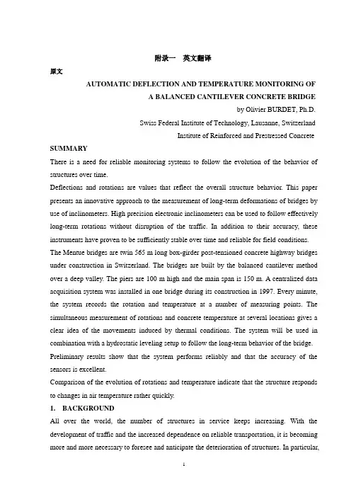
附录一英文翻译原文AUTOMATIC DEFLECTION AND TEMPERATURE MONITORING OFA BALANCED CANTILEVER CONCRETE BRIDGEby Olivier BURDET, Ph.D.Swiss Federal Institute of Technology, Lausanne, SwitzerlandInstitute of Reinforced and Prestressed Concrete SUMMARYThere is a need for reliable monitoring systems to follow the evolution of the behavior of structures over time.Deflections and rotations are values that reflect the overall structure behavior. This paper presents an innovative approach to the measurement of long-term deformations of bridges by use of inclinometers. High precision electronic inclinometers can be used to follow effectively long-term rotations without disruption of the traffic. In addition to their accuracy, these instruments have proven to be sufficiently stable over time and reliable for field conditions. The Mentue bridges are twin 565 m long box-girder post-tensioned concrete highway bridges under construction in Switzerland. The bridges are built by the balanced cantilever method over a deep valley. The piers are 100 m high and the main span is 150 m. A centralized data acquisition system was installed in one bridge during its construction in 1997. Every minute, the system records the rotation and temperature at a number of measuring points. The simultaneous measurement of rotations and concrete temperature at several locations gives a clear idea of the movements induced by thermal conditions. The system will be used in combination with a hydrostatic leveling setup to follow the long-term behavior of the bridge. Preliminary results show that the system performs reliably and that the accuracy of the sensors is excellent.Comparison of the evolution of rotations and temperature indicate that the structure responds to changes in air temperature rather quickly.1.BACKGROUNDAll over the world, the number of structures in service keeps increasing. With the development of traffic and the increased dependence on reliable transportation, it is becoming more and more necessary to foresee and anticipate the deterioration of structures. In particular,for structures that are part of major transportation systems, rehabilitation works need to be carefully planned in order to minimize disruptions of traffic. Automatic monitoring of structures is thus rapidly developing.Long-term monitoring of bridges is an important part of this overall effort to attempt to minimize both the impact and the cost of maintenance and rehabilitation work of major structures. By knowing the rate of deterioration of a given structure, the engineer is able to anticipate and adequately define the timing of required interventions. Conversely, interventions can be delayed until the condition of the structure requires them, without reducing the overall safety of the structure.The paper presents an innovative approach to the measurement of long-term bridge deformations. The use of high precision inclinometers permits an effective, accurate and unobtrusive following of the long-term rotations. The measurements can be performed under traffic conditions. Simultaneous measurement of the temperature at several locations gives a clear idea of the movements induced by thermal conditions and those induced by creep and shrinkage. The system presented is operational since August 1997 in the Mentue bridge, currently under construction in Switzerland. The structure has a main span of 150 m and piers 100 m high.2. LONG-TERM MONITORING OF BRIDGESAs part of its research and service activities within the Swiss Federal Institute of Technology in Lausanne (EPFL), IBAP - Reinforced and Prestressed Concrete has been involved in the monitoring of long-time deformations of bridges and other structures for over twenty-five years [1, 2, 3, 4]. In the past, IBAP has developed a system for the measurement of long-term deformations using hydrostatic leveling [5, 6]. This system has been in successful service in ten bridges in Switzerland for approximately ten years [5,7]. The system is robust, reliable and sufficiently accurate, but it requires human intervention for each measurement, and is not well suited for automatic data acquisition. One additional disadvantage of this system is that it is only easily applicable to box girder bridges with an accessible box.Occasional continuous measurements over periods of 24 hours have shown that the amplitude of daily movements is significant, usually amounting to several millimeters over a couple of hours. This is exemplified in figure 1, where measurements of the twin Lutrive bridges, taken over a period of several years before and after they were strengthened by post-tensioning, areshown along with measurements performed over a period of 24 hours. The scatter observed in the data is primarily caused by thermal effects on the bridges. In the case of these box-girder bridges built by the balanced cantilever method, with a main span of 143.5 m, the amplitude of deformations on a sunny day is of the same order of magnitude than the long term deformation over several years.Instantaneous measurements, as those made by hydrostatic leveling, are not necessarily representative of the mean position of the bridge. This occurs because the position of the bridge at the time of the measurement is influenced by the temperature history over the past several hours and days. Even if every care was taken to perform the measurements early in the morning and at the same period every year, it took a relatively long time before it was realized that the retrofit performed on the Lutrive bridges in 1988 by additional post-tensioning [3, 7,11] had not had the same effect on both of them.Figure 1: Long-term deflections of the Lutrive bridges, compared to deflections measured in a 24-hour period Automatic data acquisition, allowing frequent measurements to be performed at an acceptable cost, is thus highly desirable. A study of possible solutions including laser-based leveling, fiber optics sensors and GPS-positioning was performed, with the conclusion that, provided that their long-term stability can be demonstrated, current types of electronic inclinometers are suitable for automatic measurements of rotations in existing bridges [8].3. MENTUE BRIDGESThe Mentue bridges are twin box-girder bridges that will carry the future A1 motorway from Lausanne to Bern. Each bridge, similar in design, has an overall length of approximately 565 m, and a width of 13.46 m, designed to carry two lanes of traffic and an emergency lane. The bridges cross a deep valley with steep sides (fig. 2). The balanced cantilever design results from a bridge competition. The 100 m high concrete piers were built using climbing formwork, after which the construction of the balanced cantilever started (fig. 3).4. INCLINOMETERSStarting in 1995, IBAP initiated a research project with the goal of investigating the feasibility of a measurement system using inclinometers. Preliminary results indicated that inclinometers offer several advantages for the automatic monitoring of structures. Table 1 summarizes the main properties of the inclinometers selected for this study.One interesting property of measuring a structure’s rotations, is that, for a given ratio of maximum deflection to span length, the maximum rotation is essentially independent from its static system [8]. Since maximal allowable values of about 1/1,000 for long-term deflections under permanent loads are generally accepted values worldwide, developments made for box-girder bridges with long spans, as is the case for this research, are applicable to other bridges, for instance bridges with shorter spans and other types of cross-sections. This is significant because of the need to monitor smaller spans which constitute the majority of all bridges.The selected inclinometers are of type Wyler Zerotronic ±1°[9]. Their accuracy is 1 microradian (μrad), which corresponds to a rotation of one millimeter per kilometer, a very small value. For an intermediate span of a continuous beam with a constant depth, a mid-span deflection of 1/20,000 would induce a maximum rotation of about 150 μrad, or 0.15 milliradians (mrad).One potential problem with electronic instruments is that their measurements may drift overtime. To quantify and control this problem, a mechanical device was designed allowing the inclinometers to be precisely rotated of 180° in an horizontal plane (fig. 4). The drift of each inclinometer can be very simply obtained by comparing the values obtained in the initial and rotated position with previously obtained values. So far, it has been observed that the type of inclinometer used in this project is not very sensitive to drifting.5. INSTRUMENTATION OF THE MENTUE BRIDGESBecause a number of bridges built by the balanced cantilever method have shown an unsatisfactory behavior in service [2, 7,10], it was decided to carefully monitor the evolution of the deformations of the Mentue bridges. These bridges were designed taking into consideration recent recommendations for the choice of the amount of posttensioning [7,10,13]. Monitoring starting during the construction in 1997 and will be pursued after the bridges are opened to traffic in 2001. Deflection monitoring includes topographic leveling by the highway authorities, an hydrostatic leveling system over the entire length of both bridges and a network of inclinometers in the main span of the North bridge. Data collection iscoordinated by the engineer of record, to facilitate comparison of measured values. The information gained from these observations will be used to further enhance the design criteria for that type of bridge, especially with regard to the amount of post-tensioning [7, 10, 11, 12, 13].The automatic monitoring system is driven by a data acquisition program that gathers and stores the data. This system is able to control various types of sensors simultaneously, at the present time inclinometers and thermal sensors. The computer program driving all the instrumentation offers a flexible framework, allowing the later addition of new sensors or data acquisition systems. The use of the development environment LabView [14] allowed to leverage the large user base in the field of laboratory instrumentation and data analysis. The data acquisition system runs on a rather modest computer, with an Intel 486/66 Mhz processor, 16 MB of memory and a 500 MB hard disk, running Windows NT. All sensor data are gathered once per minute and stored in compressed form on the hard disk. The system is located in the box-girder on top of pier 3 (fig. 5). It can withstand severe weather conditions and will restart itself automatically after a power outage, which happened frequently during construction.6. SENSORSFigure 5(a) shows the location of the inclinometers in the main span of the North bridge. The sensors are placed at the axis of the supports (①an d⑤), at 1/4 and 3/4 (③an d④) of the span and at 1/8 of the span for②. In the cross section, the sensors are located on the North web, at a height corresponding to the center of gravity of the section (fig.5a). The sensors are all connected by a single RS-485 cable to the central data acquisition system located in the vicinity of inclinometer ①. Monitoring of the bridge started already during its construction. Inclinometers①,②and③were installed before the span was completed. The resulting measurement were difficult to interpret, however, because of the wide variations of angles induced by the various stages of this particular method of construction.The deflected shape will be determined by integrating the measured rotations along the length of the bridge (fig.5b). Although this integration is in principle straightforward, it has been shown [8, 16] that the type of loading and possible measurement errors need to be carefully taken into account.Thermal sensors were embedded in concrete so that temperature effects could be taken into account for the adjustment of the geometry of the formwork for subsequent casts. Figure 6 shows the layout of thermal sensors in the main span. The measurement sections are located at the same sections than the inclinometers (fig. 5). All sensors were placed in the formwork before concreting and were operational as soon as the formwork was removed, which was required for the needs of the construction. In each section, seven of the nine thermal sensor (indicated in solid black in fig. 6) are now automatically measured by the central data acquisition system.7. RESULTSFigure 7 shows the results of inclinometry measurements performed from the end ofSeptember to the third week of November 1997. All inclinometers performed well during that period. Occasional interruptions of measurement, as observed for example in early October are due to interruption of power to the system during construction operations. The overall symmetry of results from inclinometers seem to indicate that the instruments drift is not significant for that time period. The maximum amplitude of bridge deflection during the observed period, estimated on the basis of the inclinometers results, is around 40 mm. More accurate values will be computed when the method of determination ofdeflections will have been further calibrated with other measurements. Several periods of increase, respectively decrease, of deflections over several days can be observed in the graph. This further illustrates the need for continuous deformation monitoring to account for such effects. The measurement period was .busy. in terms of construction, and included the following operations: the final concrete pours in that span, horizontal jacking of the bridge to compensate some pier eccentricities, as well as the stressing of the continuity post-tensioning, and the de-tensioning of the guy cables (fig. 3). As a consequence, the interpretation of these measurements is quite difficult. It is expected that further measurements, made after the completion of the bridge, will be simpler to interpret.Figure 8 shows a detail of the measurements made in November, while figure.9 shows temperature measurements at the top and bottom of the section at mid-span made during that same period. It is clear that the measured deflections correspond to changes in the temperature. The temperature at the bottom of the section follows closely variations of the air temperature(measured in the shade near the north web of the girder). On the other hand, the temperature at the top of the cross section is less subject to rapid variations. This may be due to the high elevation of the bridge above ground, and also to the fact that, during the measuring period, there was little direct sunshine on the deck. The temperature gradient between top and bottom of the cross section has a direct relationship with short-term variations. It does not, however, appear to be related to the general tendency to decrease in rotations observed in fig. 8.8. FUTURE DEVELOPMENTSFuture developments will include algorithms to reconstruct deflections from measured rotations. To enhance the accuracy of the reconstruction of deflections, a 3D finite element model of the entire structure is in preparation [15]. This model will be used to identify the influence on rotations of various phenomena, such as creep of the piers and girder, differential settlements, horizontal and vertical temperature gradients or traffic loads.Much work will be devoted to the interpretation of the data gathered in the Mentue bridge. The final part of the research project work will focus on two aspects: understanding the very complex behavior of the structure, and determining the most important parameters, to allow a simple and effective monitoring of the bridges deflections.Finally, the research report will propose guidelines for determination of deflections from measured rotations and practical recommendations for the implementation of measurement systems using inclinometers. It is expected that within the coming year new sites will be equipped with inclinometers. Experiences made by using inclinometers to measure deflections during loading tests [16, 17] have shown that the method is very flexible and competitive with other high-tech methods.As an extension to the current research project, an innovative system for the measurement of bridge joint movement is being developed. This system integrates easily with the existing monitoring system, because it also uses inclinometers, although from a slightly different type.9. CONCLUSIONSAn innovative measurement system for deformations of structures using high precision inclinometers has been developed. This system combines a high accuracy with a relatively simple implementation. Preliminary results are very encouraging and indicate that the use of inclinometers to monitor bridge deformations is a feasible and offers advantages. The system is reliable, does not obstruct construction work or traffic and is very easily installed. Simultaneous temperature measurements have confirmed the importance of temperature variations on the behavior of structural concrete bridges.10. REFERENCES[1] ANDREY D., Maintenance des ouvrages d’art: méthodologie de surveillance, PhD Dissertation Nr 679, EPFL, Lausanne, Switzerland, 1987.[2] BURDET O., Load Testing and Monitoring of Swiss Bridges, CEB Information Bulletin Nr 219, Safety and Performance Concepts, Lausanne, Switzerland, 1993.[3] BURDET O., Critères pour le choix de la quantitéde précontrainte découlant de l.observation de ponts existants, CUST-COS 96, Clermont-Ferrand, France, 1996.[4] HASSAN M., BURDET O., FAVRE R., Combination of Ultrasonic Measurements and Load Tests in Bridge Evaluation, 5th International Conference on Structural Faults and Repair, Edinburgh, Scotland, UK, 1993.[5] FAVRE R., CHARIF H., MARKEY I., Observation à long terme de la déformation des ponts, Mandat de Recherche de l’OFR 86/88, Final Report, EPFL, Lausanne, Switzerland, 1990.[6] FAVRE R., MARKEY I., Long-term Monitoring of Bridge Deformation, NATO Research Workshop, Bridge Evaluation, Repair and Rehabilitation, NATO ASI series E: vol. 187, pp. 85-100, Baltimore, USA, 1990.[7] FAVRE R., BURDET O. et al., Enseignements tirés d’essais de charge et d’observations à long terme pour l’évaluation des ponts et le choix de la précontrainte, OFR Report, 83/90, Zürich, Switzerland, 1995.[8] DAVERIO R., Mesures des déformations des ponts par un système d’inclinométrie,Rapport de maîtrise EPFL-IBAP, Lausanne, Switzerland, 1995.[9] WYLER AG., Technical specifications for Zerotronic Inclinometers, Winterthur, Switzerland, 1996.[10] FAVRE R., MARKEY I., Generalization of the Load Balancing Method, 12th FIP Congress, Prestressed Concrete in Switzerland, pp. 32-37, Washington, USA, 1994.[11] FAVRE R., BURDET O., CHARIF H., Critères pour le choix d’une précontrainte: application au cas d’un renforcement, "Colloque International Gestion des Ouvrages d’Art: Quelle Stratégie pour Maintenir et Adapter le Patrimoine, pp. 197-208, Paris, France, 1994. [12] FAVRE R., BURDET O., Wahl einer geeigneten Vorspannung, Beton- und Stahlbetonbau, Beton- und Stahlbetonbau, 92/3, 67, Germany, 1997.[13] FAVRE R., BURDET O., Choix d’une quantité appropriée de précontrain te, SIA D0 129, Zürich, Switzerland, 1996.[14] NATIONAL INSTRUMENTS, LabView User.s Manual, Austin, USA, 1996.[15] BOUBERGUIG A., ROSSIER S., FAVRE R. et al, Calcul non linéaire du béton arméet précontraint, Revue Français du Génie Civil, vol. 1 n° 3, Hermes, Paris, France, 1997. [16] FEST E., Système de mesure par inclinométrie: développement d’un algorithme de calcul des flèches, Mémoire de maîtrise de DEA, Lausanne / Paris, Switzerland / France, 1997.[17] PERREGAUX N. et al., Vertical Displacement of Bridges using the SOFO System: a Fiber Optic Monitoring Method for Structures, 12th ASCE Engineering Mechanics Conference, San Diego, USA, to be published,1998.译文平衡悬臂施工混凝土桥挠度和温度的自动监测作者Olivier BURDET博士瑞士联邦理工学院,洛桑,瑞士钢筋和预应力混凝土研究所概要:我们想要跟踪结构行为随时间的演化,需要一种可靠的监测系统。
外文资料The Tenth East Asia-Pacific Conference on Structural Engineering and ConstructionAugust 3-5, 2006, Bangkok, ThailandStructural Rehabilitation of Concrete Bridges with CFRPComposites-Practical Details and ApplicationsRiyad S. ABOUTAHA1, and Nuttawat CHUTARAT2 ABSTRACT: Many old existing bridges are still active in the various highway transportation networks, carrying heavier and faster trucks, in all kinds of environments. Water, salt, and wind have caused damage to these old bridges, and scarcity of maintenance funds has aggravated their conditions. One attempt to restore the original condition; and to extend the service life of concrete bridges is by the use of carbon fiber reinforced polymer (CFRP) composites. There appear to be very limited guides on repair of deteriorated concrete bridges with CFRP composites. In this paper, guidelines for nondestructive evaluation (NDE), nondestructive testing (NDT), and rehabilitation of deteriorated concrete bridges with CFRP composites are presented. The effect of detailing on ductility and behavior of CFRP strengthened concrete bridges are also discussed and presented.KEYWORDS: Concrete deterioration, corrosion of steel, bridge rehabilitation, CFRP composites.1 IntroductionThere are several destructive external environmental factors that limit the service life of bridges. These factors include but not limited to chemical attacks, corrosion of reinforcing steel bars, carbonation of concrete, and chemical reaction of aggregate. If bridges were not well maintained, these factors may lead to a structural deficiency, which reduces the margin of safety, and may result in structural failure. In order to rehabilitate and/or strengthen deteriorated existing bridges, thorough evaluation should be conducted. The purpose of the evaluation is to assess the actual condition of any existing bridge, and generally to examine the remaining strength and load carry capacity of the bridge.1 Associate Professor, Syracuse University, U.S.A.2 Lecturer, Sripatum University, Thailand.One attempt to restore the original condition, and to extend the service life of concrete bridges is by the use of carbon fiber reinforced polymer (CFRP) composites.In North America, Europe and Japan, CFRP has been extensively investigated and applied. Several design guides have been developed for strengthening of concrete bridges with CFRP composites. However, there appear to be very limited guides on repair of deteriorated concrete bridges with CFRP composites. This paper presents guidelines for repair of deteriorated concrete bridges, along with proper detailing. Evaluation, nondestructive testing, and rehabilitation of deteriorated concrete bridges with CFRP composites are presented. Successful application of CFRP composites requires good detailing as the forces developed in the CFRP sheets are transferred by bond at the concrete-CFRP interface. The effect of detailing on ductility and behavior of CFRP strengthened concrete bridges will also be discussed and presented.2 Deteriorated Concrete BridgesDurability of bridges is of major concern. Increasing number of bridges are experiencing significant amounts of deterioration prior to reaching their design service life. This premature deterioration considered a problem in terms of the structural integrity and safety of the bridge. In addition, deterioration of a bridge has a considerable magnitude of costs associated with it. In many cases, the root of a deterioration problem is caused by corrosion of steel reinforcement in concrete structures. Concrete normally acts to provide a high degree of protection against corrosion of the embedded reinforcement. However, corrosion will result in those cases that typically experience poor concrete quality, inadequate design or construction, and harsh environmental conditions. If not treated a durability problem, e.g. corrosion, may turn into a strength problem leading to a structural deficiency, as shown in Figure1.Figure1 Corrosion of the steel bars is leading to a structural deficiency3 Non-destructive Testing of Deteriorated Concrete Bridge PiersIn order to design a successful retrofit system, the condition of the existing bridge should be thoroughly evaluated. Evaluation of existing bridge elements or systems involves review of the asbuilt drawings, as well as accurate estimate of the condition of the existing bridge, as shown in Figure2. Depending on the purpose of evaluation, non-destructive tests may involve estimation of strength, salt contents, corrosion rates, alkalinity in concrete, etc.Figure2 Visible concrete distress marked on an elevation of a concrete bridge pier Although most of the non-destructive tests do not cause any damage to existing bridges, some NDT may cause minor local damage (e.g. drilled holes & coring) that should be repaired right after the NDT. These tests are also referred to as partial destructive tests but fall under non-destructive testing.In order to select the most appropriate non-destructive test for a particular case, thepurpose of the test should be identified. In general, there are three types of NDT to investigate: (1) strength, (2) other structural properties, and (3) quality and durability. The strength methods may include; compressive test (e.g. core test/rebound hammer/ ultrasonic pulse velocity), surface hardness test (e.g. rebound hammer), penetration test (e.g. Windsor probe), and pullout test (anchor test).Other structural test methods may include; concrete cover thickness (cover-meter), locating rebars (rebar locator), rebar size (some rebar locators/rebar data scan), concrete moisture (acquameter/moisture meter), cracking (visual test/impact echo/ultrasonic pulse velocity), delamination (hammer test/ ultrasonic pulse velocity/impact echo), flaws and internal cracking (ultrasonic pulse velocity/impact echo), dynamic modulus of elasticity (ultrasonic pulse velocity), Possion’s ratio (ultrasonic pulse velocity), thickness of concrete slab or wall (ultrasonic pulse velocity), CFRP debonding (hammer test/infrared thermographic technique), and stain on concrete surface (visual inspection).Quality and durability test methods may include; rebar corrosion rate –field test, chloride profile field test, rebar corrosion analysis, rebar resistivity test, alkali-silica reactivity field test, concrete alkalinity test (carbonation field test), concrete permeability (field test for permeability).4 Non-destructive Evaluation of Deteriorated Concrete Bridge PiersThe process of evaluating the structural condition of an existing concrete bridge consists of collecting information, e.g. drawings and construction & inspection records, analyzing NDT data, and structural analysis of the bridge. The evaluation process can be summarized as follows: (1) Planning for the assessment, (2) Preliminary assessment, which involves examination of available documents, site inspection, materials assessment, and preliminary analysis, (3) Preliminary evaluation, this involves: examination phase, and judgmental phase, and finally (4) the cost-impact study.If the information is insufficient to conduct evaluation to a specific required level, then a detailed evaluation may be conducted following similar steps for the above-mentioned preliminary assessment, but in-depth assessment. Successful analytical evaluation of an existing deteriorated concrete bridge should consider the actual condition of the bridge and level of deterioration of various elements. Factors, e.g. actual concrete strength, level of damage/deterioration, actual size of corroded rebars, loss of bond between steel and concrete, etc. should be modeled into a detailed analysis. If such detailed analysis is difficult to accomplish within a reasonable period of time, thenevaluation by field load testing of the actual bridge in question may be required.5 Bridge Rehabilitation with CFRP CompositesApplication of CFRP composite materials is becoming increasingly attractive to extend the service life of existing concrete bridges. The technology of strengthening existing bridges with externally bonded CFRP composites was developed primarily in Japan (FRP sheets), and Europe (laminates). The use of these materials for strengthening existing concrete bridges started in the 1980s, first as a substitute to bonded steel plates, and then as a substitute for steel jackets for seismic retrofit of bridge columns. CFRP Composite materials are composed of fiber reinforcement bonded together with a resin matrix. The fibers provide the composite with its unique structural properties. The resin matrix supports the fibers, protect them, and transfer the applied load to the fibers through shearing stresses. Most of the commercially available CFRP systems in the construction market consist of uniaxial fibers embedded in a resin matrix, typically epoxy. Carbon fibers have limited ultimate strain, which may limit the deformability of strengthened members. However, under traffic loads, local debonding between FRP sheets and concrete substrate would allow for acceptable level of global deformations before failure.CFRP composites could be used to increase the flexural and shear strength of bridge girders including pier cap beams, as shown in Figure3. In order to increase the ductility of CFRP strengthened concrete girders, the longitudinal CFRP composite sheets used for flexural strengthening should be anchored with transverse/diagonal CFRP anchors to prevent premature delamination of the longitudinal sheets due to localized debonding at the concrete surface-CFRP sheet interface. In order to prevent stress concentration and premature fracture of the CFRP sheets at the corners of concrete members, the corners should be rounded at 50mm (2.0 inch) radius, as shown in Figure3.Deterioration of concrete bridge members due to corrosion of steel bars usually leads in loss of steel section and delamination of concrete cover. As a result, such deterioration may lead to structural deficiency that requires immediate attention. Figure4 shows rehabilitation of structurally deficient concrete bridge pier using CFRP composites.Figure3 Flexural and shear strengthening of concrete bridge pier with FRP compositesFigure4 Rehabilitation of deteriorated concrete bridge pier with CFRP composites6 Summary and ConclusionsEvaluation, non-destructive testing and rehabilitation of deteriorated concrete bridges were presented. Deterioration of concrete bridge components due to corrosion may lead to structural deficiencies, e.g. flexural and/or shear failures. Application of CFRP composite materials is becoming increasingly attractive solution to extend the service life of existing concrete bridges. CFRP composites could be utilized for flexural and shear strengthening, as well as for restoration of deteriorated concrete bridge components. The CFRP composite sheets should be well detailed to prevent stress concentration and premature fracture or delamination. For successful rehabilitation of concrete bridges in corrosive environments, a corrosion protection system should be used along with the CFRP system.第十届东亚太结构工程设计与施工会议2006年8月3-5号,曼谷,泰国碳纤维复合材料修复混凝土桥梁结构的详述及应用Riyad S. ABOUTAHA1, and Nuttawat CHUTARAT2摘要:在各式各样的公路交通网络中,许多现有的古老桥梁,在各种恶劣的环境下,如更重的荷载和更快的车辆等条件下,依然在被使用着。

土木工程桥梁方向毕业设计外文及翻译(总13页)--本页仅作为文档封面,使用时请直接删除即可----内页可以根据需求调整合适字体及大小--学生姓名:学号:班级:专业:土木工程(桥梁方向)指导教师:2010 年 3 月What is traffic engineeringTraffic engineering is still a relatively new discipline within the overall bounds of civil engineering. it has nevertheless already been partially planning. the disciplines are not synonymous though. transportation planning is concerned with the planning, functional design, operation and management of facilities for any mode of transportation in order to provide for the safe, rapid, comfortable, convenient, economical and enviromenally-comparible movement of people and goods. within that broad scope, traffic engineering deals with those functions in respect of roads, road networks, terminal points , about lands and their relationships with other modes of transportation.Those definitions, based on the 1976 ones of the of transportation engineers are complete than, the British instituting of civil engineering which deals with traffic planning and design of roads, of frontage development and of parking facilities and with the control of traffic to provide safe, convenient and economical movement of vehicles and pedestrians.The definitions of the disicipline are becoming clearer: the methodology is developing continuously and becoming increasingly scientific. the early rule-of-thumb techniques are disappearing.Traffic problemThe discipline is young: the problem is large and still growing. in 1920 the total number of motor vehicles, licensed in great Britain was,650, year later the comparable figure was 14,950,000-a growth factor of 23 times. in recent years the rate of growth has slackened somewhat, but it is still considerable: 1955 6,466,0001960 9,439,0001965 12,938,0001970 14,950,0001974 17,247,000In order to see the problem in every day terms ,consider high street. anywhere. assuming that present trends continue, it is expected that within the next fifteen years of so the traffic on this road will increase by around forty to fifty persent. if this increased volume of traffic were to be accommodated at the same standard as today, the road might need to be widened by a similar forty to fifty percent-perhaps extra lane of traffic for the pedestrian to cross. In man cases, to accommodate the foreseeable future demand would destroy the character of the whole urban environment, and is clearly unacceptable.the traffic problem is of world-wide concern, but different countries are obviously at different stages in the traffic escalation-with America in the lead, while a county has few roads and a relatively low problem, as soon as the country is opened up by a road system, the standard of living and the demand for motor transport both rise, gathering momentum rapidly. eventually-and the stage at which this happens is open to considerable debate-the demand for cars, buses and lorries become satiated. the stage is known as saturation level.For comparison ,car ownership figures in different countries in 1970 were:India cars/personIsrael personJapan cars/personIreland cars/personNetherlands cars/personGreat Britain cars/personWest Germany cars/personAustralia cars/personUSA cars/personBut the growth in vehicle ownership is only part of the overall traffic problem. obviously,if a country has unlimited roads of extreme width, the traffic problem would not rise. no country in the world could meet this requirement: apart from anything else, it would not make economic for each vehicle using the roads. This figure is decreasing steadily.Three possible solutionsThe basic problem of traffic is therefore simple-an ever-increasing number of vehicles seeking to use too little roade space. the solution to the problem-is else a not-too-difficult choice from three possiblilities:build, sufficient roads of sufficient size to cope with the demand.Restrict the demand for roads by restricting the numbers of licensed vehicles.A compromise between (a) and (b) build some extra roads, using the and the existing road network to their full potential, and at the same time apply some restraint measures, limiting, the increase in demand as far as possible.With no visible end to the demand yet in sight, and 216 with modern road-making costs ranging around £1 million per kilometer cost of building roads in Britain to cope with an unrestricted demand would be far too great. added to this, such clossal use of space in a crowed island cannot be, seriously considered. in Los Angeles, a city built around the parking space for, the automobile. our citie are already largely built-and no one would consider ruining their character by pulling them down and rebuilding around the car, thus the first possible soluting is rule out.Even today,in an age of at least semi-affluence in most of the Western World, the car is still to some extent a status symbol, a symbol of family wants to own one, and takes steps saving or borrowing-to get one. as incomes and standards rise thesecond car becomes the target. any move to restrict the acquisition of the private car would be most unpopular-and politically unlikely.For many purpose the flexibility of the private car-conceptually affording door-to-door personal transport is ideal, and its use can be accommodate. for the mass, movement of people along specific corridors within a limited period of .. particularly the journey to work it may be less easily accommodated. other transport mode may be more efficient. some sort of compromise solution is the inevitable answer to the basic traffic problem .it is in the execution of the compromise solution that, traffic engineering comes into its own. traffic engineering ensures that any new facilities are not over-deigned and are correctly located to meet the demand. it ensures that the existing facilities are fully used, in the most efficient manner. the fulfillment of these duties may entail the selective throttling of demand: making the use of the car less attractive in the peak periods in order that the limited road space can be more efficiently used by public transport.Such restraint measures will often be accompanied by improvements in the public transport services, to accommodate the extra demand for them.Prestressed Concrete BridgesPrestressed concrete has been used extensively in . bridge construction since its first Introduction from Europe in the late 1940s. Literally thousands of highway bridges of both precast, prestressed concrete and cast-in-place post-tensioned concrete has been constructed in the United States. Railroad bridges utilizing prastressed concrete have become common as well. The use and evolution of prastressed concrete bridges is expected to continue in the years ahead.Short-span BridgesShort-span bridges will be assumed to have a maximum of 45 ft .It should be understood that this is an arbitrary figure, and there is no definite line of demarcation between short, moderate, and long spans in highway bridges. Short-span bridges are most efficiently made of precast ,prestressed-concrete hollow slabs, I-beams, solid slabs or cast-place solid slabs. and T-beams of relatively generous proportions.Precast solid slabs are most economical when used on very short spans. The slabs can be made in any convenient width,but widths of 3 or 4 ft to have been frequently are cast in the longitudinal sides of the precast units. After the slabs have been erected and the joints between the slabs have been filled with concrete, the keys transfer live load shear forces between the adjacent slabs.Precast hollow slabs used in short-span bridges may have round or square voids. They too are generally made in units 3 to 4 ft to m) wide with thicknesses from 18 to 27 in to . Precast hollow slabs can be made in any convenient width and depth, and frequently are used in bridges having spans from 20 to 50 ft to . Longitudinal shear keys are used in the joints between adjacent hollow slabs in the same way as with solid slabs. Hollow slabs may or may not be used with a composite, cast-in-place concrete topping an accecptable appearance and levelness.Transverse reinforcement normally is provided in precast concrete bridge superstructures for the purpose of tying the structure together in the transverse direction. Well-designed ties ensure that the individual longitudinal members forming the superstructure will act as a unit under the effects of the live load. In slab bridge construction, transverse ties most frequently consist of threaded steel bars placed through small holes formed transversely through the member during fabrication. Nuts frequently are used as fasteners at each end of the bars. In some instances, the transverse ties consist of post tensionedtendons placed, stressed, and grouted after the slabs have been erected. The transverse tie usually extends from one side of the bridge to the other.The shear forces imposed on the stringers in short-span bridges frequently are too large to be resisted by the concrete alone. Hence, shear reinforcement normally is required. The amount of shear reinforcement required may be relatively large if the webs of the stringers are relatively thin.Concrete diaphragms, reinforced with post-tensioned reinforcement or nonprestressed reinforcement, normally are provided transversely at the ends and at intermediate locations along the span in stringer-type bridges. The disaphragms ensure the lateral-distribution of the live load to the various stringers and prevent individual stringers from displacing or rotating significantly with respect to the adjacent stringers.No generalities will be made here about the relative cost of each of the above types of construction; construction costs are a function of many variables which prohibit meaningful generalizations. However, it should be noted that the stringer type of construction requires a considerably greater construction depth that is required for solid, hollow, or channel slab bridge superstructures. Stringer construction does not require a separate wearing surface, as do the precast slab types of construction, unless precast slabs are used to span between the stringers in lieu of the more commonly used cast-in-place reinforced concrete deck. Stringer construction frequently requires smaller quantities of superstructure materials than do slab bridges (unless the spans are very short). The construction time needed to complete a bridge after the precast members have been erected is greater with stringer framing than with the slab type of framing.Bridges Of Moderate SpanAgain for the purpose of this discussion only, moderate spans for bridges of prestressed concrete are defined as beingfrom 45 to 80 ft to . Prestressed concrete bridges in this span range generally can be divided into two types: stringer-type bridges and slab-type bridges. The majority of the precast prestressed concrete bridges constructed in the United States have been stringer bridges using I-shaped stringers, but a large number of precast prestressed concrete bridges have been constructed with precast hollow-box girders (sometimes also called stringers). Cast-in-place post-tensioned concrete has been used extensively in the construction of hollow-box girder bridges-a form of construction that can be considered to be a slab bridge.Stringer bridges, which employ a composite, cast-in-place deck slab, have been used in virtually all parts of the United States. These stringers normally are used at spacing s of about 5 to 6 ft to . The cast-in-place deck is generally from to in to in thickness. This type of framing is very much the same as that used on composite-stringer construction for short-span bridges.Diaphram details in moderate-span bridges are generally similar to those of the short spans, with the exception that two or three interior diaphragms sometime are used, rather than just one at midspan as in the short-span bridge.As in the case of short-span bridges, the minimum depth of construction in bridges of moderate span is obtained by using slab construction, which may be either solid – or hollow – box in cross section. Average construction depths are requires when stringers with large flanges are used in composite construction, and large construction depths are required when stringers with small bottom flanges are used. Composite construction may be developed through the use of cast-in-place concrete decks or with precast concrete decks. Lower quantities of materials normally are required with composite construction , and the dead weight of the superstructure normally is less for stringer construction than for slab construction.Long-Span BridgesPrestressed concrete bridges having spans of the order of 100ft are of the same general types of construction as structures having moderate span lengths, with the single exception that solid slabs are not used for long spans. The stringer spacings are frequently greater (with stringers at 7 to 9 ft) as the span lengths of bridges increase. Because of dead weight considerations, precast hollow-box construction generally is employed for spans of this length only when the depth of construction must be minimized. Cast-in-place post-tensioned hollow-box bridges with simple and continuous spans frequently are used for spans on the order of 100 ft and longer.Simple, precast, prestressed stringer construction would be economical in the United States in the spans up to 300 ft under some conditions. However, only limited use has been made of this type of construction on spans greater than 100 ft. For very long simple spans, the advantage of precasting frequently is nullified by the difficulties involved in handling, transporting, and erecing the girders, which may have depths as great as 10 ft and weigh over 200 tons. The exceptions to this occur on large projects where all of the spans are over water of sufficient depth and character that precast beams can be handled with floating equipment, when custom girder launchers can be used, and when segmental construction techniques can be used.The use of cast-in-place , post-tensioned, box-girder bridges has been extensive. Although structures of these types occasionally are used for spans less than 100ft, they more often are used for spans in excess of 100 ft and have been used in structuresHaving spans in excess of 300 ft. Structurally efficient in flexure, especially for continuous bridges, the box girder is torsionally stiff and hence an excellent type of structure for use on bridges that have horizontal curvature. Some governmental agencies use this form of construction almost exclusively in urban areas where appearance from underneath the superstructure,as well as from the side, is considered important.交通工程介绍什么是交通工程交通工程仍然是在土木工程的总的界限内的一种相对新的训练。

外文文献翻译BRIDGE ENGINEERING AND AESTHETICSEvolvement of bridge Engineering,brief reviewAmong the early documented reviews of construction materials and structure types are the books of Marcus Vitruvios Pollio in the first century B.C.The basic principles of statics were developed by the Greeks , and were exemplified in works and applications by Leonardo da Vinci,Cardeno,and Galileo.In the fifteenth and sixteenth century, engineers seemed to be unaware of this record , and relied solely on experience and tradition for building bridges and aqueducts .The state of the art changed rapidly toward the end of the seventeenth century when Leibnitz, Newton, and Bernoulli introduced mathematical formulations. Published works by Lahire (1695)and Belidor (1792) about the theoretical analysis of structures provided the basis in the field of mechanics of materials .Kuzmanovic(1977) focuses on stone and wood as the first bridge-building materials. Iron was introduced during the transitional period from wood to steel .According to recent records , concrete was used in France as early as 1840 for a bridge 39 feet (12 m) long to span the Garoyne Canal at Grisoles, but reinforced concrete was not introduced in bridge construction until the beginning of this century . Prestressed concrete was first used in 1927.Stone bridges of the arch type (integrated superstructure and substructure) were constructed in Rome and other European cities in the middle ages . These arches were half-circular , with flat arches beginning to dominate bridge work during the Renaissance period. This concept was markedly improved at the end of the eighteenth century and found structurally adequate to accommodate future railroad loads . In terms of analysis and use of materials , stone bridges have not changed much ,but the theoretical treatment was improved by introducing the pressure-line concept in the early 1670s(Lahire, 1695) . The arch theory was documented in model tests where typical failure modes were considered (Frezier,1739).Culmann(1851) introduced the elastic center method for fixed-end arches, and showed that three redundant parameters can be found by the use of three equations of coMPatibility.Wooden trusses were used in bridges during the sixteenth century when Palladio built triangular frames for bridge spans 10 feet long . This effort also focused on the three basic principles og bridge design : convenience(serviceability) ,appearance , and endurance(strength) . several timber truss bridges were constructed in western Europe beginning in the 1750s with spans up to 200 feet (61m) supported on stone substructures .Significant progress was possible in the United States and Russia during the nineteenth century ,prompted by the need to cross major rivers and by an abundance of suitable timber . Favorable economic considerations included initial low cost and fast construction .The transition from wooden bridges to steel types probably did not begin until about 1840 ,although the first documented use of iron in bridges was the chain bridge built in 1734 across the Oder River in Prussia . The first truss completely made of iron was in 1840 in the United States , followed by England in 1845 , Germany in 1853 , and Russia in 1857 . In 1840 , the first iron arch truss bridge was built across the Erie Canal at Utica .The Impetus of AnalysisThe theory of structuresThe theory of structures ,developed mainly in the ninetheenth century,focused on truss analysis, with the first book on bridges written in 1811. The Warren triangular truss was introduced in 1846 ,supplemented by a method for calculating the correcet forces .I-beams fabricated from plates became popular in England and were used in short-span bridges.In 1866, Culmann explained the principles of cantilever truss bridges, and one year later the first cantilever bridge was built across the Main River in Hassfurt, Germany, with a center span of 425 feet (130m) . The first cantilever bridge in the United States was built in 1875 across the Kentucky River.A most impressive railway cantilever bridge in the nineteenth century was the First of Forth bridge , built between 1883 and 1893 , with span magnitudes of 1711 feet (521.5m). At about the same time , structural steel was introduced as a prime material in bridge work , although its quality was often poor . Several early examples are the Eads bridge in St.Louis ; the Brooklyn bridge in New York ; and the Glasgow bridge in Missouri , all completed between 1874 and 1883.Among the analytical and design progress to be mentioned are the contributions of Maxwell , particularly for certain statically indeterminate trusses ; the books by Cremona (1872) on graphical statics; the force method redefined by Mohr; and the works by Clapeyron who introduced the three-moment equations.The Impetus of New MaterialsSince the beginning of the twentieth century , concrete has taken its place as one of the most useful and important structural materials . Because of the coMParative ease with which it can be molded into any desired shape , its structural uses are almost unlimited . Wherever Portland cement and suitable aggregates are available , it can replace other materials for certain types of structures, such as bridge substructure and foundation elements .In addition , the introduction of reinforced concrete in multispan frames at the beginning of this century imposed new analytical requirements . Structures of a high order of redundancy could not be analyzed with the classical methods of the nineteenth century .The importance of joint rotation was already demonstrated by Manderla (1880) and Bendixen (1914) , who developed relationships between joint moments and angular rotations from which the unknown moments can be obtained ,the so called slope-deflection method .More simplifications in frame analysis were made possible by the work of Calisev (1923) , who used successive approximations to reduce the system of equations to one simple expression for each iteration step . This approach was further refined and integrated by Cross (1930) in what is known as the method of moment distribution .One of the most import important recent developments in the area of analytical procedures is the extension of design to cover the elastic-plastic range , also known as load factor or ultimate design. Plastic analysis was introduced with some practical observations by Tresca (1846) ; and was formulated by Saint-Venant (1870) , The concept of plasticity attracted researchers and engineers after World War Ⅰ, mainly in Germany , with the center of activity shifting to England and the United States after World War Ⅱ.The probabilistic approach is a new design concept that is expected to replace the classical deterministic methodology.A main step forward was the 1969 addition of the Federal Highway Adiministration (FHWA)”Criteria for Reinforced Concrete Bridge Members “ that covers strength and serviceability at ultimate design . This was prepared for use in conjunction with the 1969 American Association of State Highway Offficials (AASHO) Standard Specification, and was presented in a format that is readily adaptable to the development of ultimate design specifications .According to this document , the proportioning of reinforced concrete members ( including columns ) may be limited by various stages of behavior : elastic , cracked , andultimate . Design axial loads , or design shears . Structural capacity is the reaction phase , and all calculated modified strength values derived from theoretical strengths are the capacity values , such as moment capacity ,axial load capacity ,or shear capacity .At serviceability states , investigations may also be necessary for deflections , maximum crack width , and fatigue . Bridge TypesA notable bridge type is the suspension bridge , with the first example built in the United States in 1796. Problems of dynamic stability were investigated after the Tacoma bridge collapse , and this work led to significant theoretical contributions Steinman ( 1929 ) summarizes about 250 suspension bridges built throughout the world between 1741 and 1928 .With the introduction of the interstate system and the need to provide structures at grade separations , certain bridge types have taken a strong place in bridge practice. These include concrete superstructures (slab ,T-beams,concrete box girders ), steel beam and plate girders , steel box girders , composite construction , orthotropic plates , segmental construction , curved girders ,and cable-stayed bridges . Prefabricated members are given serious consideration , while interest in box sections remains strong .Bridge Appearance and AestheticsGrimm ( 1975 ) documents the first recorded legislative effort to control the appearance of the built environment . This occurred in 1647 when the Council of New Amsterdam appointed three officials . In 1954 , the Supreme Court of the United States held that it is within the power of the legislature to determine that communities should be attractive as well as healthy , spacious as well as clean , and balanced as well as patrolled . The Environmental Policy Act of 1969 directs all agencies of the federal government to identify and develop methods and procedures to ensure that presently unquantified environmental amentities and values are given appropriate consideration in decision making along with economic and technical aspects .Although in many civil engineering works aesthetics has been practiced almost intuitively , particularly in the past , bridge engineers have not ignored or neglected the aesthetic disciplines .Recent research on the subject appears to lead to a rationalized aesthetic design methodology (Grimm and Preiser , 1976 ) .Work has been done on the aesthetics of color ,light ,texture , shape , and proportions , as well as other perceptual modalities , and this direction is both theoretically and empirically oriented .Aesthetic control mechanisms are commonly integrated into the land-use regulations and design standards . In addition to concern for aesthetics at the state level , federal concern focuses also on the effects of man-constructed environment on human life , with guidelines and criteria directed toward improving quality and appearance in the design process . Good potential for the upgrading of aesthetic quality in bridge superstructures and substructures can be seen in the evaluation structure types aimed at improving overall appearance .LOADS AND LOADING GROUPSThe loads to be considered in the design of substructures and bridge foundations include loads and forces transmitted from the superstructure, and those acting directly on the substructure and foundation .AASHTO loads . Section 3 of AASHTO specifications summarizes the loads and forces to be considered in the design of bridges (superstructure and substructure ) . Briefly , these are dead load ,live load , iMPact or dynamic effect of live load , wind load , and other forces such as longitudinal forces , centrifugal force ,thermal forces , earth pressure , buoyancy , shrinkage andlong term creep , rib shortening , erection stresses , ice and current pressure , collision force , and earthquake stresses .Besides these conventional loads that are generally quantified , AASHTO also recognizes indirect load effects such as friction at expansion bearings and stresses associated with differential settlement of bridge components .The LRFD specifications divide loads into two distinct categories : permanent and transient .Permanent loadsDead Load : this includes the weight DC of all bridge components , appurtenances and utilities, wearing surface DW and future overlays , and earth fill EV. Both AASHTO and LRFD specifications give tables summarizing the unit weights of materials commonly used in bridge work .Transient LoadsVehicular Live Load (LL)Vehicle loading for short-span bridges :considerable effort has been made in the United States and Canada to develop a live load model that can represent the highway loading more realistically than the H or the HS AASHTO models . The current AASHTO model is still the applicable loading.桥梁工程和桥梁美学桥梁工程的发展概况早在公元前1世纪,Marcus Vitrucios Pollio 的著作中就有关于建筑材料和结构类型的记载和评述。

Long and light——《Bridge design & engineering》Closure of the main span on the Sundoya Bridge in Norway is expected to take place in the first week after Easter. This graceful crossing, the second longest of its type in the world, is being built in situ using high performance concreteSundoya Bridge is situated in one of Norway's most scenic areas, only 100km south of the Arctic Circle. The 538m-long bridge spans Sundet, and when it is complete will provide a ferry-free road connection between Sundoya and the mainland. It is located some 35km west of the city of Mosjoen, close to highway 78 between Mosjoen and Sandnessjoen.It will be the second large bridge project connecting Alstenoya to the mainland, coming more than 12 years after the Helgeland Bridge was opened. The region is no stranger to world-record scale bridges ?the Helgeland Bridge's 425m long main span was the longest cable-stayed span in the world when it opened in 1992.Sundoya Bridge is divided into three spans; it has a main span of 298m and two side spans of 120m. The main span will be the second longest span in the world for a continuous post-tensioned cast in place box section concrete bridge.In terms of its design, consultant Dr Ing Aas-Jakobsen has followed a similar approach to that taken for the Raftsundet Bridge, opened in 1998, to which the Sundoya Bridge will almost be a twin. The two bridges have identical main spans, but Raftsundet has four spans as opposed to Sundoya's three. Contractor AS Anlegg, which is part of the joint venture building Sundoya, was also the contractor on the Raftsundet Bridge, and architect Boarch Arkitekter has also worked on the two schemes.In January 2001 the joint venture company AF Sundoybrua won the contract from client Statens Vegvesen to build the Sundoya Bridge. This joint venture consisted of the contractors Reinertsen Anlegg and NCC Construction.High performance concrete is central to the design of the bridge ?both normal weight HPC and lightweight HPC. Normal weight concrete, at approximately 2500kg/m3, is used for the 120m side spans, while lightweight concrete, which weighs in at about 1970kg/m3, is used for construction of the 298m main span. This enables construction to proceed using the balanced cantilever method.Local rock from Norway is used as the aggregate for the normal weight concrete, but the lightweight concrete required an imported solution. Normally the aggregate used for lightweight concrete in Europe is expanded clay or shale, but this material has high levels of absorption and for this reason, regulations prevent such concrete from being pumped.In order to address this, the contractor adopted a similar solution to that used on RaftsundetBridge ?importing Stalite aggregate from South Carolina in the USA. Stalite is produced through thermal expansion of high quality slate, and results in a lightweight aggregate that gives concrete of very high strength at low unit weights. Its low absorption of approximately 6% and high particle strength are two of the factors that allow Stalite to achieve high strength concrete in excess of 82.7MPa, the manufacturer says. The bondand compatibility of the aggregate with cement paste reduce micro-cracking and enhance durability, and its low absorption makes it easy to mix and pump.According to AF Sundoybrua quality manager Jan-Eirik Nilsskog, this material has given a very good result. It produces concrete that is easy to pour into the formwork and it gives a good surface finish, he says. It is being pumped some 120m along the bridge deck to the concreting position. Concrete is produced by a transportable mobile plant located only 1km from the bridge site. Constant monitoring of the concrete weight is necessary to ensure that the cantilevers are properly balanced. This is tested for each pour.The project began in January 2001 at Aker Verdal with the production of caissons for the pier bases. In May 2001 the two caissons were towed 500km north to the bridge site.The bridge is being poured in situ using special mobile construction equipment developed by NRS. The cycle for construction of each 5m wide bridge segment is a week, and two mobile units are being used on the Sundoya Bridge. These particular units were built for AS Anlegg to use on the Varodden Bridge in Kristiansand in Norway, and they have also been used by the same contractor on the Rafsundet Bridge. The design of the central part of the main span of the bridge is based on the use of lightweight concrete LC60 while other parts of the structure use the more standard type C65. Because of the aggressive marine environment, the quality of the concrete must be particularly good.The structure is a single cell, prestressed rectangular box girder, largely built using the travelling formwork system from NRS. The box width is 7m and its depth varies from 3m at the centre of the span to 14.5m over the piers. Close to the abutments, concrete of quality C25 will be used inside the box girder as ballast. In addition, the designers have included the necessary elements inside the box girder in order to allow the possible addition of post-tensioning cables in the future. The long-term behaviour of such large spans is not fully known, so the possibility that the main span may sag over time has to be taken into account. The width of the road is a constant 7.5m from the barrier on one side to that on the other, and the total width of the bridge is some 10.3m. There is a 2m wide footway included in the width of the structure.The pier shaft is formed with twin legs, which are hollow inside. The pier shafts incorporate permanent prestressing cables and they have a constant wall thickness and a width that varies parabolically over their height.Temporary tie-down piers are used to construct the bridge - they are located 35m into each 120m-long side span from the main piers. Each consists of an I-shaped shaft, which is tied down to the ground using rock anchors and connected to the box girder by means of prestressing cables. The purpose of these structural elements is to support the cantilever and prevent rotation in strong winds. Once the bridge superstructure is complete and the main pier prestressing is fully tensioned, the temporary tie-down pierswill be removed piece by piece.The location of the bridge, only about 100km south of the Arctic Circle, has meant that special measures have to be introduced to allow construction work to continue all year round. Apart from the obvious need to provide site lighting for much of the wintertime, the challenge of concreting in temperatures which can be as low as 0 C has to be overcome. Hot concrete is produced for the bridge ?sometimes up to 30 C and the formwork has to be insulated to keep the concrete warm. Electric heating cables are also used on the end of the previous pour to warm up the concrete before casting.Construction of the new bridge began in January 2000 and is expected to be complete in September this year. The construction of the cantilever started in summer last year and is due to be finished in April. When Bd&e went to press, the project was on schedule for opening to traffic in late autumn.Project TeamClient: Statens VegvesenContractor: AF Sundoybrua (AS Anlegg, NCC Construction)Consultant: Dr Ing Aas-JakobsenArchitect: Boarch Arkitekter超轻大跨度桥——Sundoya挪威的在Sundoya 桥上的主跨有望在复活节的后第一个星期望合龙. 它是一座大跨度的,在世界的它的同类型中第二长,建造在situ 的长大桥。
第二部分英文翻译Reliability analysis :a structures management tool for concrete bridgesReinforced concrete structures are susceptible to a variety of deterioration mechanisms, including alkali-thaw action and chloride ingress. Substantial research has been undertaken in relation to these mechanisms and other problems. This has particularly been the case over the last 20 years or so, where the objective has been to identify causes, consequences and develop remediation strategies. This has improved understanding of long-term behaviour of reinforced concrete and resulted in the development of techniques to increase deterioration resistance.At present, the most common approach is to act after a problem has been identified, known as re-active maintenance. This may not be the most economic solution since, in many cases, maintenance is more costly than preventative treatments. However, owners are often reluctant to pay for preventative treatments before deterioration is apparent. Early application of treatments may not be the optimal solution in the long run. Integrated deterioration and performance prediction modeling is essential to pro-actively plan and prioritise inspection, testing and maintenance. This becomes increasingly important as infrastructure ages and justification for maintenance funding becomes increasingly critical.Performance assessment can be achieved through surveys, testing and formal calculations, ideally based on site data that represent, as accurately as possible, the state of the structure. By integrating predictive deterioration models with assessment tools and performance criteria (at element, structure or group level) it becomes possible to base the maintenance regime on time-dependent performance profiles. This is particularly relevant in the context of whole-wife costing procedures.Substantial research has been undertaken in relation to these mechanisms and other problems. This has particularly been the case overthe last 20 years or so, where the objective has been to identify causes, consequences and develop remediation strategies. This has improved understanding of long-term behaviour of reinforced concrete and resulted in the development of techniques to increase deterioration resistance.At present, the most common approach is to act after a problem has been identified, known as re-active maintenance. This may not be the most economic solution since, in many cases, maintenance is more costly than preventative treatments. However, owners are often reluctant to pay for preventative treatments before deterioration is apparent. Early application of treatments may not be the optimal solution in the long run. Integrated deterioration and performance prediction modeling is essential to pro-actively plan and prioritise inspection, testing and maintenance. This becomes increasingly important as infrastructure ages and justification for maintenance funding becomes increasingly critical.Reliability analysis has emerged as an important tool in this multi-objective management process, which must take into account safety, functionality and sustainability criteria. In simple terms, the reliability of a structure or a system is the probability of achieving a particular performance level. Probability or likelihood is the appropriate measure, since all engineering systems are susceptible to uncertainties, arising from random phenomena and incomplete knowledge. Reliability analysis in structural engineering enables quantification of uncertainties associated with loading, materials, deterioration, modeling and other factors. These are integrated into a method that estimates the probability of reaching the specified performance level during the service life of a structure. The method is increasingly being used in bridge engineering, both for calibration of safety levels in codes and standards and improving and refining assessment methodologies. The purpose of this article is to outline its application in managing bridges susceptible to deterioration.Although data for many deterioration variables can be derived from laboratory studies, there is an absence of similar data real structures. Animportant feature of the model is the facility to modify initial predictions, based on published (known as ‘prior’) data, using information and data obtained directly from the actual structures. Reliability analysis is appropriate for this pursose as if it can readily incorporate additional data, updating the probability of reaching a performance target. The concept is analogous to updating the probability of arriving on time whilst on a train, having just obtain some extra information regarding the operating conditions ahead.Typical results produced by the probabilistic deterioration model for a crossbeam chloride exposure zone, similar to the delaminated area shown in Figure 3,are shown in Figure 4.Assuming a threshold of 40% initiation is specified for the first inspection, the model suggests that it should be undertaken after eight years .Assuming that inspection indicates significantly less corrosion initiation (e.g.only about 10%) and attributed, through site investigations, to concrete cover being higher than expected, a revised prediction of the performance profile may be generated .The bridge management actions may then be altered accordingly.Figure 5 illustrates how a limit state profile for this zone changes with assumed conditions. The deterioration model has been integrated with bond limit state equations .Thus, assuming that the component has a target nominal probability of failure of 1×10⁻⁵ per year, profile 1 suggests a lifetime of only 17 to 18 years, whereas Profile 2 suggests 30 to 31 years. Both are short lifetimes when compared with the normal life expectancy of bridges. However, initial conditions relating to these results assume that the deck joint has failed from the outset .Alternatively ,the expressions for modelling bond strength may be over-conservative ,as they were developed for intact structures.Substantial research has been undertaken in relation to these mechanisms and other problems. This has particularly been the case over the last 20 years or so, where the objective has been to identify causes, consequences and develop remediation strategies. This has improvedunderstanding of long-term behaviour of reinforced concrete and resulted in the development of techniques to increase deterioration resistance.At present, the most common approach is to act after a problem has been identified, known as re-active maintenance. This may not be the most economic solution since, in many cases, maintenance is more costly than preventative treatments. However, owners are often reluctant to pay for preventative treatments before deterioration is apparent. Early application of treatments may not be the optimal solution in the long run. Integrated deterioration and performance prediction modeling is essential to pro-actively plan and prioritise inspection, testing and maintenance. This becomes increasingly important as infrastructure ages and justification for maintenance funding becomes increasingly critical.Bridge performance criteriaCurrent UKassessment codes are concerned with ultimate limit states (ULS) and do not explicitly require checking of serviceability limit states (ULS). It is assumed that an existing structure has experienced SLS loads during its life. However, the widely accepted SLS criteria of deflection and cracking do not fully take into account the problems posed by deterioration. Deterioration-based criteria such as rust staining, delamination and spalling need to be considered because they clearly influence bridge performance, both functional and financial. These often prove the dominant factor with regard to bridge management strategy.By explicitly considering and specifying performance levels, the engineer is aware of the important deterioration indicators in order to establish the inspection and maintenance regime for the particular structure/member. These performance levels may change over time, due to changes in function, loading, structure importance etc. for example, the relationship between actual and required performance is conceptualized by the diagram shown in Figure 1. Thus, reliability analysis may be used to formulate the probability that performance will exceed that required, thereby estimating the reliability of the structure. The performancemeasure can be related to safety, functionality or any other appropriate criterion.Modeling chloride-induced deteriorationThis particular project concentrated on one specific area of reinforced concrete deterioration, specifically arising from chloride ingress. Chlorides are present in de-icing salts used in the UK during winter. Chloride ions migrate though the concrete, e.g. by absorption and diffusion. Under suitable conditions, they initiate reinforcement bar corrosion. The corrosion mechanism produces rust. The increased volume of the metal, due to the rust, leads to cracking, delamination and spalling of the concrete cover. This results in more rapid and extensive reinforcement corrosion.Reinforced concrete bridge elements located below expansion joints are particularly susceptible to chloride attack if the joint fails. Highway viaducts in the UK typically consist of a reinforced concrete crossbeam directly located below the expansion joint,(see Figure 2).Many crossbeams have suffered severe reinforcement corrosion, delamination and spalling. A typical example is shown in Figure 3, where the reinforcement cover over the crossbeam has delaminated.A probabilistic deterioration model for reinforced concrete bridge components was developed, taking into account the characteristics of these structures and their environment. It assumes that both diffusion and absorption play a part in chlotide migration through the concrete, the variability in the quantity of de-icing salts reaching the crossbeam surface and how these quantities vary annually. Typical chloride exposure zones considered for the crossbeams include the:●Horizontal surface below a failedexpansion joint where water ponding can occur●vertical surface below a failed expansion jointsurfaces below an intact expansion joint, but exposed to traffic spray etc.Although data for many deterioration variables can be derived from laboratory studies, there is an absence of similar data real structures. An important feature of the model is the facility to modify initial predictions, based on published (known as ‘prior’) data, using information and data obtained directly from the actual structures. Reliability analysis is appropriate for this pursose as if it can readily incorporate additional data, updating the probability of reaching a performance target. The concept is analogous to updating the probability of arriving on time whilst on a train, having just obtain some extra information regarding the operating conditions ahead.Typical results produced by the probabilistic deterioration model for a crossbeam chloride exposure zone, similar to the delaminated area shown in Figure 3,are shown in Figure 4.Assuming a threshold of 40% initiation is specified for the first inspection, the model suggests that it should be undertaken after eight years .Assuming that inspection indicates significantly less corrosion initiation (e.g.only about 10%) and attributed, through site investigations, to concrete cover being higher than expected, a revised prediction of the performance profile may be generated .The bridge management actions may then be altered accordingly.Laboratory and site data are essential for improved deterioration modeling and reliability .Much data collection and test interpretations made in the deterioration models. Given the costs associated with maintaining safe, reliable infrastructure systems, this is an area where a concreted effort by industry and organizations could yield substantial benefits.Figure 5 illustrates how a limit state profile for this zone changes with assumed conditions. The deterioration model has been integrated with bond limit state equations .Thus, assuming that the component has a target nominal probability of failure of 1×10⁻⁵ per year, profile 1 suggests a lifetime of only 17 to 18 years, whereas Profile 2 suggests 30 to 31 years. Both are short lifetimes when compared with the normal lifeexpectancy of bridges. However, initial conditions relating to these results assume that the deck joint has failed from the outset .Alternatively ,the expressions for modelling bond strength may be over-conservative ,as they were developed for intact structures.Concluding remarksReliability analysis provides a rational and consistent framework for treating uncertainties .It can be a useful management tool with which similar structures can be compared through performance profiles which change over time. The results must be interpreted with care, and stand up to common sense and engineering judgement . Sensitivity analysis is strongly recommended, and can be readily performed.Laboratory and site data are essential for improved deterioration modeling and reliability .Much data collection and test interpretations made in the deterioration models. Given the costs associated with maintaining safe, reliable infrastructure systems, this is an area where a concreted effort by industry and organizations could yield substantial benefits.AcknowledgementsThis work was performed with the support of the Highways Agency. The views expressed are those of the authors and are not necessarily shared by the Highways Agency.可靠性分析——混凝土桥的结构处理工具钢筋混凝土桥结构对多种恶化机制敏感,包括碱趋于和缓行动和氯化物进入。
毕业设计(论文)外文资料翻译系别:专业:班级:姓名:学号:外文出处:土木工程网附件: A.英文文献; B. 译文附录A英文文献BridgesBridges are great symbols of mankind’s conquest of space.The sight of the crimson tracery of the Golden Gate Bridge against a setting sun in the Pacific Ocean, or the atch of the Garabit Biaduct soaring triumphantly above the deep gorge. Fills one’s heart with wonder and admiration for the art of their builders[11]. They are the enduring expressions of mankind’s determination to remove all barriers in its pursuit of a better and freer world. Their design and building schemes are conceived in dream-like bisions. But vision and determination are not enough. All the physical forces of nature and gravity must be understood with mathematical precision and such forces have to be resisted by manipulating the right materials in the right pattern. This requires both the inspiration of an artist and the skill of an artisan.Scientific knowledge about materials and structural behavior has expanded tremendously, and computing techniques are now widely available to manipulate complex theories in innumerable ways very quickly. Engineers have virtually revolutionized bridge design and construction methods in the past decade. The advances apply to short-medium and long-span bridges.For permanent bridge,the most commonly used materials are steel and concrete. Bridge of many different type are built with these materials, used singly or in combination. Timber may be used for temporary above-water construction, for the elements of a structure that lie below the waterline (particularly timber pile s), or for short-span bridges located on secondary roads. A few short-span aluminum bridges have been built in the United States on an experimental basis.The principal portions of a bridge may be said to be the “substructure” and the “superstructure.” This division is used here simply for convenience, since in many bridges there is no clear dividing lint between the two.Common elements of the substructure are abutments (usually at the bridge ends) and piers (between the abutments).Piers and abutments often rest on separately constructed foundations such as concrete spread footings or groups of bearing piles;these foundations are part of the substructure. Occasionally a bridge substructure comprises a series of pile bents in which the piles extend above the waterline and are topped by a pile cap that, in turn, supports the major structural elements of the superstructure. Such bents often are used in arepetitive fashion as part of along, low, over-water crossing.In recent years, the dividing lines between short-medium and long-span bridge have blurred somewhat. Currently, spans of 20 to 100 ft (6.1 to 30.5m) are regarded as short by many designers, who have developed many standardized designs to handle these spans economically. Medium spans range up to, per-haps, 400ft (121.9m) in modern bridge practice, depending on the organization involved and the materials used. Long spans range up to 4000ft (1219.2m) or more, but a clear span above 1000ft (304.8m)is comparatively rare.In the United States, highway bridges generally must meet loading, design, and construction requirements of the AASHTO Specification. The design and construction of railway bridges are governed by provisions of the AREA Manual for Railway Engineering. Design requirements for pedestrian crossings and bridges serving other purposes may be established by local or regional codes and specifications. ACI Code provisions are often incorporated by reference, and in most cases serve as model provisions for other governing documents.Bridge spans to about 100 ft often consist of pre-cast integral-deck units. These units offer low initial cost, minimum maintenance, and fast easy constrction, with traffic interruption. Such girders are generally pretensioned, the units are placed side by side, and are often post-tensioned laterally at intermediate diaphragm lacations, After which shear keys between adjacent units are filled with non-shrinking mortar. For highway spans, an asphalt wearing surface may be applied directly to the top of the pre-cast concrete. In some cases, a cast-in-place slab is placed to provide composite action.For medium-span highway bridges, to about 120 ft, AASHTO standard I beams are generally used. he are intended for use with a composite cast-in-place roadway slab. Such girders often combine pre-tensioning of the pre-cast member withpost-tensioning of the composite beam after the deck is placed.Pre-cast girders may not be used for spans much in excess of 120 ft because of the problems of transporting and erecting large, heavy units. On the other hand, there is a clear trend toward the use of longer spans for bridges. Highway safety is improved by eliminating central piers and moving outer piers away from the edge of divided highways. For elevated urban expressways, long spans facilitate access and minimize obstruction to activities below. Concern for environmental damage has led to the choice of long spans for continuous viaducts. For river crossing, intermediate piers may be impossible because of requirements of navigational clearance.Such requirements have led to the development in Europe, and more recently in the western hemisphere, of long span segmental pre-stressed concrete box girder bridges. In typical construction of this type, piers are cast-in-place, often using the slip-forming technique. A “hammerhead” section of box girder is then cast at the top of the pier, and construction proceeds in each direction by the balanced cantilever method. The construction is advanced using either cast-in-place or pre-cast segments, each post-tensioned to the previously completed construction. Finally, after the closing cast-in-place joint is made at mid-span, the structure is further post-tensioned for full continuity.Bridge may also be classed as “deck” or “through” types. In the deck type of bridge, the roadway is above the supporting structure; that is, the load-carrying elements of the superstructure are below the roadway. In the through type of bridge, the roadway passes between the elements of the super-structure, as in a through steel-truss bridge. Deck structures predominate: they have a clean appearance, provide the motorist with a better view of the surrounding area, and are easier to widen if future traffic requires it.Examples of short-span concrete bridges include cast-in-lace, reinforced concrete beam (and slab);simple-span, pre-stressed (this type incorporates pre-cast, pre-stressed I-girders or box girders topped by a cast-in-place deck);and cast-in place box girder.The designer of each medium-and long-span bridge tries to devise a structurethat is best suited to the conditions encountered at that particular location. The result is an almost bewildering variety of structures that differ either in basic design principles or in design details.General categories of steel bridge are briefly described in the following paragraphs.Girder bridges come in two basic varieties-plate and box girders.Plate girders are used in the United States for medium spans. They generally are continuous structures with maximum depth of girder over the piers and minimum depth at mid-span. The plate girders generally have an I cross section; they are arranged in lines that support stringers, floor-beams, and, generally, a cast-in-lace concrete deck. The girders are shop-fabricated by welding; field connections generally are by high-strength bolts.Welded-steel box girder structures are generally similar to plate girder spans except for the configuration of the bridge cross section.Rigid frames are used occasionally, most often for spans in the range of 75 to 100 ft (22.9 to 30.5 m) and for grade0separation structures.Arch bridges are used for longer spans at locations where intermediate piers cannot be used and where good rock is available to withstand the thrusts at the arch abutments.Variations in the arch bridge are specially suited in the span range of 200 to 500m and thus provide a transition between the continuous box girder bridge and the stiffened suspension cable. The cables provided above the deck and connected to the towers would permit elimination of intermediate piers facilitating a larger width for purposes of navigation. Because of the damping effect of inclined cables, the cable-stayed decks are less prone to wind-induced oscillations than suspension bridges.Suspension bridges are used for very long spans or for shorter spans where intermediate piers cannot be built. An example is the Verrazano Narrows Bridge which was completed in 1964.The $305 million,4260ft(1298.5m)structure spans the entrance to New York Harbor to join Staten Island and Brooklyn.Concrete bridges come in nearly as great a variety as do steel bridges.The bridge construction in France benefits by a strong growth in rail and highway infrastructures. For the time being the competition with other material turns to the advantage of composite bridge solutions. Before presenting any features concerning the recent trends in composite bridge design it is important to clarify, the bridge market, through the analysis of some statistical data.In France, there is a very limited market for long span bridges. In the recent construction, the demand for bridges of span length higher than 200m is rather exceptional. The main market is for bridges of span length (or multi span length) less than 100m.In France 800 to 1200 bridges are built every year, which represent about 300,000m to 500,000m of deck surface. However the majority of bridges being erected each year are of small span length. Less than 10% of the bridge patrimony have span. Length greater than 30m and deck surface greater than 1000 m2. Now that the market has been identified lets have an idea, in term of competitiveness, of the French market situation between several bridge types. In 1977 less than 2.5%.Of bridges were steel or composite bridges. The steel-concrete composite construction has continued to grow steadily over the last 15 years. This trend is mainly attributable to the gain in competitiveness of composite bridges against reinforcedand prestressed concrete bridges.For short span length the majority of steel bridges is of concrete type. Bridges composed of steel beams encased in concrete are very often used for railway bridges of small span length in order to meet stiffness requirements.The recent statistical evaluation, performed by SETRA [1] on the bridges recently built in France between 1990 to 1993 by various owners (State, Highway concession companies, Departments and Communities, SNCF) shows that the competitive span length range for steel and concrete composite bridges is between 30 and 110 m with a very distinctive peak for the interval 60 to 80 m. In that range of spans length it is noticed that 85% of bridges being built belong to the composite category (Fig. 4).The statistical analysis of the deck cost per square metre of surface confirms that the average price for a composite bridge is less than the price for a concrete bridge for spans length within intervals of 40 to 60 m and 60 to 80 m. The difference being of 1 500 FF/m2 over a total cost of 8 200 FF/m2 (VAT excluded) in favour of the composite bridge. It means that an 18% cost difference represents a great shift in terms of competition.The last 15 years have seen a great simplification of composite bridges for both roadway and railway bridges, which have made them, as previously indicated, very competitive compared to prestressed and reinforced bridges. These composite bridges, that we will name them as classical, have however several features which are described hereafter. Then, from these classical features, improvements have been constantly brought to the design and execution of composite bridges, which will be depicted later on.The traditional composite roadway bridge is composed of two longitudinal girders which are connected to the concrete slab by shear connectors (usually welded stud are mostly met; however steel angle connectors are still used). A limited number of transverse cross beams joining the two longitudinal girders, usually not connected to the slab — see half cross section (a) are welded to the vertical stiffeners. The main girders have a few numbers of horizontal stiffeners, if any which are mostly needed to resist the stress state in the girder webs occurring at the launching phase.Plain concrete is formed form a hardened mixture of cement, water, fine aggregate, coarse aggregate (crushed stone or gravel), air, and often other admixtures. The plastic mix is placed and consolidated in the formwork, then cured to facilitate the acceleration of the chemical hydration reaction of the cement/water mix, resulting in hardened concrete. The finished product has high compressive strength, and low resistance to tension, such that its tensile strength is approximately one-tenth of its compressive strength. Consequently, tensile and shear reinforcement in the tensile regions of sections has to be provided to compensate for the weak-tension regions in the reinforced concrete element.It is this deviation in the composition of a reinforced concrete section from thehomogeneity of standard wood or steel sections that requires a modified approach to the basic principles of structural design. The two components f the heterogeneous reinforced concrete section are to be so arranged and proportioned that optimal use is made of the materials involved. That is possible because concrete can easily be given any desired shape by placing and compacting the wet mixture of the constituent ingredients into suitable forms in which the plastic mass hardens. If the various ingredients are properly proportioned, the finished product becomes strong, durable, and, in combination with the reinforcing bars, adaptable for use as main members of any structural system.The techniques necessary for placing concrete depend on the type of member to be cast: that is, whether it is a column, a beam, a wall, a slab, a foundation, amass concrete dam, or an extension of previously placed and hardened concrete. For beams, columns, and walls, the forms should be well oiled after cleaning them, and the reinforcement earth should be compacted and thoroughly moistened to about 6 in. in depth to avoid absorption of the moisture present in the wet concrete. Concrete should always be placed in horizontal layers which are compacted by means of high-prequency power-driven vibrators of either the immersion or external type, as the case requires, unless it is placed by pumping. It must be kept in mind, however, that over vibration can be harmful since it could cause segregation of the aggregate and bleeding of the concrete.Hydration of the cement takes place in the presence of moisture at temperatures above F50. It is necessary to maintain such a condition in order that the chemical hydration reaction can take place. If drying is too rapid, surface cracking takes place. This would result in reduction of concrete strength due to cracking as well as the failure to attain full chemical hydration.It is clear that a large number of parameters have to be dealt with in proportioning a reinforced concrete element, such as geometrical width, depth, area of reinforcement, steel strain, concrete strain, steel strees, and so on. Consequently, trial and adjustment is necessary in the choice of concrete sections, with assumptionsbased on conditions at site, availability of the constituent materials, particular demands of the owners, architectural and headroom requirements, the applicable codes, and environmental conditions. Such an array of parameters has to be considered because of the fact that reinforced concrete is often a site-constructed composite, in contrast to the standard mill-fabricate beam and column sections in steel structures.A trial section has to be chosen for each critical location in a structural system. The trial section has to be analyzed to determine if its nominal resisting strength is adequate to carry the applied factored load. Since more than one trial is often necessary to arrive at the required section, the first design input step generates into a series of trial-and-adjustment analyses.The trial-and-adjustment procedures for the choice of a concrete section lead to the convergence of analysis and design. Hence every design is an analysis once a trial section is chosen. The availability of approach as a more efficient, compact, and speedy instructional method compared with the traditional approach of treating the analysis of reinforced concrete separately from pure design.The rapid growth from 1945 onwards in the prestressing of concrete shows that there was a real need for this high-quality material. The quality must be high because the worst conditions of loading normally occur at the beginning of the life of the member, at the transfer of stress later, when the concrete has become stronger and the stress in the steel has decreased because of creep in the steel and the concrete, and shrinkage of the concrete. Faulty members are therefore observed and thrown out early, before they enter the structure, or at least before it becomes inconvenient and expensive to remove them.The main advantages of prestressed concrete in comparison with reinforced concrete are:(a) The whole concrete cross-section resists load. In reinforced concrete about half the section, the cracked area below the neutral axis, does no useful work. Working deflections are smaller.(b) High working stresses are possible. In reinforced concrete they are notusually possible because hey result in severe cracking which is always ugly and may be dangerous if it causes rusting of the steel.(c) Cracking is almost completely avoided in prestressed concrete.The main disadvantage of prestressed concrete is that much more care is needed to make it than reinforced concrete and it is therefore more expensive, but because it is of higher quality less of it needs to be used.It can therefore happen that a solution of a structural problem may be cheaper in prestressed concrete than in reinforced concrete, and it does often happen that a solution is possible with prestressing but impossible without it.Prestressing of the concrete means that it is placed under compression before it carries any working load. This means that the section can be designed so that it takes no tension or very little under the full design load. It therefore has theoretically no cracks and in practice the concrete in which it is embedded has hardened. After the concrete has hardened enough to take the stress from the steel, some of the stress is transferred from the steel to the concrete. In a bridge with abutments able to resist thrust, the prestress can be applied without steel in the concrete. It is applied by jacks forcing the bridge inwards from the abutments. This method has the advantage that the jacking force, or prestress, can be varied during the life of the structure as required.In the ten years from 1950 to 1960 prestressed concrete ceased to be an experimental material and engineers won confidence in its use. With this confidence came an increase in the use of precast prestressed concrete particularly for long-span floors or the decks of motorways. Wherever the 500 m long, provided that most of the spans could be made the same and not much longer than 18 m, it became economical to use factory-precast prestressed beams, at least in industrial areas near a precasting factory. Most of these beams are heat-cured so as to free the forms quickly or reuse.In this period also, in the United States, precast prestressed roof beams and floor beams were used in many school buildings, occasionally 32 m long or more. Such long beams over a single span could not possibly be successful in reinforced concrete unless they were cast on site because they would have to be much deeper and muchheavier than prestressed concrete beams. They would certainly be less pleasing to the eye and often more expensive than the prestressed concrete beams. These school buidings have a strong, simple architectural appeal and will be a pleasure to look at for many years.The most important parts of a precast prestressed concrete beam are the tendons and the concrete. The tendons, as the name implies, are the cables, rods or wires of steel which are under tension in the concrete. Before the concrete has hardened (before transfer of stress), the tendons are either unstressed (post-tensioned prestressing) or are stressed and held by abutments outside the concrete (pre-tensioned prestressing). While the concrete is hardening it grips each tendon more and more tightly by bond along its full length. End anchorages consisting of plates or blocks are placed on the ends of the tendons of post-tensioned prestressed units, and such tendons are stressed up at the time of transfer, when the concrete has hardened sufficiently. In the other type of presstressing, with pre-tensioned tondons, the tendons are released from external abutments at the moment of transfer, and act on the concrete through bond or anchorage or both, shortening it by compression, and themselves also shortening and losing some tension.Further shortening of the concrete (and therefore of the steel) takes place with time. The concrete is said to creep. This means that it shortens permanently under load and spreads the stresses more uniformly and thus more safely across its section. Steel also creeps, but rather less. The result of these two effects (and of the concrete shrinking when it dries) is that prestressed concrete beams are never more highly stressed than at the moment of transfer.The factory precasting of long prestressed concrete beams is likely to become more and more popular in the future, but one difficulty will be road transport. As the length of the beam increases, the lorry becomes less and less manoeuvrable until eventually the only suitable time for it to travel is in the middle of the night when traffic is at a minimum. The limit of length for road transport varies tith the traffic in the district and the route, whether the roads are straight or curved. Precasting at the site avoids these difficulties; it may be expensive, but it has often been used for largebridge beams.Materials for building must have certain physical properties to be structurally useful. Primarily, they must be able to carry a load, or weight, without changing shape per- manently. When a load is applied to a structure member, it will deform; that is, a wire will stretch or a beam will bend. However, when the load is removed, the wire and the beam come back to the original positions. This material property is called elasticity. If a material were not elastic and a deformation were present in the structure after removal of the load, repeated loading and unloading eventually would increase the deformation to the point where the structure would become useless .All materials used in architect- tural structures, such as stone and brick, wood, steel, aluminum, reinforced concrete, and plastics, behave elastically within a certain defined range of loading. If the loading is increased above the range, two types of behavior can occur: brittle and plastic. In the former, the material will break suddenly. In the latter, the material begins to flow at a certain load (yield strength), ultimately leading to fracture. As examples, steel exhibits plastic behavior, and stone is brittle. The ultimate strength of a material is measured by the stress at which failure (fracture) occurs.A second important property of a building material is its stiffness. This property is defined by the elastic modulus, which is the ratio of the stress (force per unit area), to the strain (deformation per unit length). The elastic modulus, therefore, is a measure of the resistance of a material to deformation under load. For two materials of equal area under the same load, the one with the higher elastic modulus has the smaller deforma- tion. Structural steel, which has an elastic modulus of 30 million pounds per square in- ch (psi), or 2 100 000 kilograms per square centimeter, is 3 time as stiff as aluminum, 10 times as stiff as concrete, and 15 times as stiff as wood.Masonry consists of natural materials, such as stone, or manufactured products, such as brick and concrete blocks. Masonry has been used since ancient times; mud bricks were used in the city of Babylon for secular buildings, and stone was used for the great temples of the Nile Valley. The Great Pyramid in Egypt, standing 481 feet (147 meters) high, is the most spectacular masonry construction. Masonry units origin- nally were stacked without using any bonding agent, but all modern masonryconstruc- tion uses a cement mortar as a bonding material. Modern structural materials include stone, brick of burnt clay or slate, and concrete blocks.Masonry is essentially a compressive material; it cannot withstand a tensile force, that is, a pull. The ultimate compressive strength of bonded masonry depends on the strength of the masonry unit and the mortar. The ultimate strength will vary from 1 000 to 4 000 psi (70 to 280 kg/sq cm), depending on the particular combination of masonry unit and mortar used.Timber is one of the earliest construction materials and one of the few natural ma- terials with good tensile properties. Hundreds of different species of wood are found throughout the world, and each species exhibits different physical characteristics. Only a few species are used structurally as framing members in building construction. In the United States, for instance, out of more than 600 species of wood, only 20 species are used structurally. These are generally the conifers, or softwoods, both because of their abundance and because of the ease with which their wood can be shaped. The species of timber more commonly used in the United States for construction are Douglas fir, Southern pine, sqruce, and redwood. The ultimate tensile strength of these species varies from 5 000 to 8 000 psi (350 to 560 kg/sq cm). Hardwoods are used primarily for cabinetwork and for interior finishes such as floors.Because of the cellular nature of wood, it is stronger along the grain than across the grain. Wood is particularly strong in tension and compression parallel to the grain. And it has great bending strength. These properties make it ideally suited for columns and beams in structures. Wood is not effectively used as a tensile member in a truss, however, because the tensile strength of a truss member depends upon connections between members. It is difficult to devise connections which do not depend on the shear or tearing strength along the grain, although numerous metal connectors have been produced to utilize the tensile strength of timbers.Steel is an outstanding structural material. It has a high strength on a pound-for- pound basis when compared to other materials, even though its volume-for-volume weight is more than ten times that of wood. It has a high elastic modulus, which results in small deformations under load. It can be formed by rolling into variousstructural shapes such as I-beams, plates, and sheets; it also can be cast into complex shapes; and it is also produced in the form of wire strands and ropes for use as cables in suspension bridges and suspended roofs, as elevator ropes, and as wires for prestressing concrete. Steel elements can be joined together by various means, such as bolting, riveting, or welding. Carbon steels are subject to corrosion through oxidation and must be protected from contact with the atmosphere by painting them or embedding them in concrete. Above temperatures of about 700F (3710C), steel rapidly loses its strength, and there- fore it must be covered in a jacket of a fireproof material (usually concrete) to increase its fire resistance.The addition of alloying elements, such as silicon or manganese, results in higher strength steels with tensile strengths up to 250 000 psi (17 500 kg/sq cm). These steels are used where the size of a structural member becomes critical, as in the case of co- lumns in a skyscraper.Aluminum is especially useful as a building material when lightweight, strength, and corrosion resistance are all important factors. Because pure aluminum is extremely soft and ductile, alloying elements, such as magnesium, silicon, zinc, and copper, must be added to it to impart the strength required for structural use. Structural aluminum alloys behave elastically. They have an elastic modulus one third as great as steel and therefore deform three times as much as steel under the same load. The unit weight of an aluminum alloy is one third that of steel, and therefore an aluminum member will be lighter than a steel member of comparable strength. The ultimate tensile strength of aluminum alloys ranges from 20 000 to 60 000 psi (1 400 to 4 200 kg/sq cm).Aluminum can be formed into a variety of shapes; it can be extruded to form I- beams, drawn to form wire and rods, and rolled to form foil and plates. Aluminum members can be put together in the same way as steel by riveting, bolting, and (to a lesser extent) by welding. Apart from its use for framing members in buildings and prefabricated housing, aluminum also finds extensive use for window frames and for the skin of the building in curtain-wall construction.Concrete is a mixture of water, sand and gravel, and portland cement. Crushed。
文献翻译Bridge Maintenance TechniquesEssential maintenance generally involves strengthening or replacement of bridge elements . Strengthening techniques include welding , plate bonding and external post-tensioning which increase the stiffness of bridge decks . Replacement of elements has been used for deck slabs and beams, piers and columns. The primary purpose of essential maintenance is to increase the load carrying capacity and the reason for the inadequate capacity is secondary . If the reason is simply increased loading the maintenance can be limited to increasing the capacity , but if the reason is deterioration then maintenance must also include repairs and preventative maintenance.The selection of the maintenance method for repairs prevention depends primarily on the cause of deterioration . For steel construction the main cause of deterioration is corrosion and regular maintenance painting should be carried out to prevent the steel from corroding . If corrosion does occur then the only repair option is to grit blast back to shiny metal before repainting . An assessment of load carrying capacity should be carried out if corrosion has resulted in a significant reduction of steel section .The selection of repair and prevention methods for concrete construction is more complex because there are numerous causes of concrete deterioration .The deterioration of reinforced concrete can be conveniently sub-divided into deterioration of the concrete and deterioration of the steel reinforcement . The main causes of concrete deterioration are sulphates , free-thaw cycles and alkali-silica reaction(ASR). Deterioration can also be related to poor mix design and construction process such as compaction and curing . These types of deterioration can only be prevented by actions taken at the time of construction ; there are no effective preventative actions that can be taken after construction. For example where the environment is known to contain significant quantities of sulphide it is sensible to consider the use of sulphate resisting Portland cement . In regions experiencing large numbers of freeze-thaw cycles frost damage to concrete can be prevented by adding air entraining agent to the concrete mix . Frost damage is worse in concrete that is saturated with salty water so techniques such as waterproofing membranes and silane treatments may be helpful . Alkali-silica reaction between aggregates and the alkali in cement can be prevented by avoiding the most reactive types of aggregate and by keeping the alkali content of the cement below the designated limit . To set up damaging stresses in concrete the ASR requires water so procedures to reduce the water content such as waterproofing membranes and silane treatments may help . If these forms of concrete deterioration take place the only viable repair method is concrete replacement which may be extensive especially for ASR where entire sections can be affected . Sulphate and freeze-thaw damage normally occur only in the coverzone of the concrete . It is important to note that deterioration of the concrete will increase the risk of corrosion to the reinforcement because steel depassivators , like chlorides and carbon dioxide , will be able to move more easily through the concrete to the reinforcement .Deterioration of the reinforcing steel is caused by corrosion and can be prevented by actions taken at the time of construction and for a period after construction . Preventative techniques that can be applied at construction include the use of epoxy coated mild steel , stainless steel of carbon or glass fibre reinforcement , inhibitors , cathodic protection , anti-carbonation coatings , silane treatments and waterproofing membranes . All of these techniques , except the last three , directly protect the reinforcement against corrosion and to date , have been used only occasionally largely on grounds of cost . Waterproofing membranes , silane treatments , and anti-carbonation coatings are applied to the concrete and are designed to slow down the ingress of carbon dioxide and chlorides into the concrete thereby increasing the age of the structure when the reinforcement begins to corrode . These techniques can be used after construction because they are applied to the concrete surface and they should be effective , providing corrosion of the reinforcement has not already begun . It is important not to overlook the importance of well compacted and cured, low water : cement ratio concrete in preventing reinforcement corrosion.When corrosion of the reinforcement occurs it result in a loss of steel section and/or cracking, spalling and delamination of concrete due to the stresses produced as a result of the low density of rust compared with density of the steel . Reinforcement corrosion repair methods have two main functions , to crete replacement ; cathodic protection ; desalination ; realkalization.Concrete replacement has to be used to repair the damage caused by corrosion regardless of which technique is used to stop corrosion . Concrete replacement can also be used to stop corrosion although this involves the removal of all the carbonated and chloride contaminated concrete even though it is physically sound . This often means that concrete repairs to stop corrosion are not economically viable . Cathodic protection can be applied at any time to stop corrosion caused by carbonation or chlorides . It functions by making the reinforcing steel cathodic with respect to an external anode system . Cathodic protection requires a permanent electrical installation . Desalination can be used to stop corrosion caused by chlorides and it works by migrating chloride ions towards an external anode and away from the reinforcing steel in an electric field ; this process takes about 6 weeks . Realkalization stops corrosion caused by carbonation and it works by migrating sodium ions from an external anolyte into the concrete where in combination with the hydroxyl ions generated on the reinforcing steel due to the electric field , the alkalinity is raised to a level where the steel re-passivates . Realkalization takes about 4 weeks . Desalination ,realkalization and concrete repair are not normally used in conjunction with a preventative treatment such as silane or an anti-carbonation coating to increase the life of the repair .Cathodic protection does not requireadditional preventative measures because it is a permanent installation , but the anodes do require periodic replacement.大桥维修技术大桥的基本的维修大体上包括加强和更换桥的基本元素。
Accident Analysis and PreventionThis paper describes a project undertaken to establish a self-explaining roads (SER) design programmeon existing streets in an urban area. The methodology focussed on developing a process to identifyfunctional road categories and designs based on endemic road characteristics taken from functionalexemplars in the study area. The study area was divided into two sections, one to receive SER treatments designed to maximise visual differences between road categories, and a matched control area to remainuntreated for purposes of comparison. The SER design for local roads included increased landscaping andcommunity islands to limit forward visibility, and removal of road markings to create a visually distinctroad environment. In comparison, roads categorised as collectors received increased delineation, additionof cycle lanes, and improved amenity for pedestrians. Speed data collected 3 months after implementationshowed a significant reduction in vehicle speeds on local roads and increased homogeneity of speeds onboth local and collector roads. The objective speed data, combined with r esidents’ speed choice ratings,indicated that the project was successful in creating two discriminably different road categories.2010 Elsevier Ltd. All rights reserved.1. Introduction1.1. BackgroundChanging the visual characteristics of roads to influencedriver behaviour has come to be called the self-explaining roads(SER) approach (Theeuwes, 1998; Theeuwes and Godthelp, 1995;Rothengatter, 1999). Sometimes referred to as sustainable safety,as applied in the Netherlands, the logic behind the approach isthe use of road designs that evoke correct expectations and drivingbehaviours from road users (Wegman et al., 2005; Weller etal., 2008). The SER approach focuses on the three key principlesof functionality, homogeneity, and predictability (van Vliet andSchermers, 2000). In practice, functionality requires the creation ofa few well-defined road categories (e.g., through roads, distributorroads, and access roads) and ensuring that the use of a particularroad matches its intended function. Multifunctional roadslead to contradictory design requirements, confusion in the mindsof drivers, and incorrect expectations and inappropriate drivingbehaviour. Clearly defined road categories promote homogeneity intheir use and prevent large differences in vehicle speed, direction,and mass. Finally, predictability, or recognisability, means keepingthe road design and layout within each category as uniform as possibleand clearly differentiated from other categories so that thefunction of a road is easily recognised and will elicit the correctbehaviour from road users. The SER approach has been pursued tothe largest extent in the Netherlands and the United Kingdom but ithas also been of some interest inNewZealand. In 2004, the NationalRoad Safety Committee and the Ministry of Transport articulateda new National Speed Management Initiative which stated “Theemphas is is not just on speed limit enforcement, it includes perceptualmeasures that influence the speed that a driver feels is appropriatefor the section of road upon which they are driving–in effect the ‘selfexplainingroad”’ (New Zealand Ministry of Transport, 2004).In cognitive psychological terms, the SER approach attempts toimprove road safety via two complementary avenues. The first is toidentify and use road designs that afford desirable driver behaviour.Perceptual properties such as road markings, delineated lane width,and roadside objects can function as affordances that serve as builtininstructions and guide driver behaviour, either implicitly orexplicitly (Charlton, 2007a; Elliott et al., 2003; Weller et al., 2008).This work is more or less a direct development of work on perceptualcountermeasures, perceptual cues in the roading environmentthat imply or suggest a particular speed or lane position, eitherattentionally or perceptually (Charlton, 2004, 2007b; Godley et al.,1999).A second aspect of the SER approach is to establish mentalschemata and scripts, memory representations that will allowroad users to easily categorise the type of road on which they are.1.2. Localised speed managementThe traditional approaches to improving speed management,traffic calming and local area traffic management (LATM) havefocussed on treating specific problem locations or “black spots”in response to crash occurrences or complaints from the public(Ewing, 1999). A potential disadvantage of these approaches is thataddressing the problem with localised treatments can lead to are-emergence of the problem at another location nearby. Further,when applied inappropriately, localised approaches may addressthe problem from only one perspective, without considering theimpact on other types of road users or residents. When traffic calmingtreatments rely on physical obstacles such as speed humpsthey can be very unpopular with bothresidents and road users andcan create new problems associated with noise, maintenance, andvandalism (Martens et al., 1997).From an SER perspective, treatments that are highly localizedor idiosyncratic may do more harm than good by adding to themultiplicity of road categories and driver uncertainty, rather thanbuilding driver expectations around a few uniform road types.Instead of considering a single location in isolation, SER roaddesigns are considered within a hierarchy of road functions; e.g.,access roads, collector roads, and arterial roads. Although SERschemes may employ physical design elements used in trafficcalming schemes (e.g., road narrowing with chicanes and accesscontrols) they also employ a range of more visually oriented featuressuch as median and edge line treatments, road markings,pavement surfaces, and roadside furniture. For an effective SERscheme it is important to select the combination of features that will afford the desired driver speeds and to ensure their consistentuse to form distinct categories of road types (van der Horst andKaptein, 1998; Wegman et al., 2005).road category that would meet the three SER principles of functional use, homogeneous use, and predictable use. Herrstedt (2006)reported on the use of a standardised catalogue of treatments compiledfrom researcher and practitioner advice. Goldenbeld and vanSchagen (2007) used a survey technique to determine road characteristicsthat minimise the difference between drivers’ ratingsof preferred speed and perceived safe speed and select road featuresthat make posted speeds “credible”. Aarts and Davidse (2007)used a driving simulator to verify whether the “essential recognisabilitycharacteristics” of different road classes conformed to theexpectations of road users. Weller et al. (2008) employed a range of statistical techniques, including factor analysis and categoricalclustering to establish the road characteristics that drivers use tocategorise different road types.The practical difficulties of implementing an SER system thusbecome a matter of finding answers to a series of questions. Howdoes one create a discriminable road hierarchy for an existingroad network? What road characteristics should be manipulatedto establish category-defining road features? How can SER roadfeatures and selection methods be made relevant and appropriatefor a local context? (Roaddesigns appropriate for The Netherlandswould not be suitable in New Zealand, in spite of its name.) A surveyof national and international expert opinion in order establishcategory-defining road features for New Zealand roads revealedthat the regional character and local topography of roads oftenundercut the usefulness of any standardised catalogue of designcharacteristics (Charlton and Baas, 2006).1.4. Goals of the present projectThe project described in this paper sought to develop anddemonstrate an SER process based on retrofitting existing roadsto establish a clear multi-level road hierarchy with appropriatedesign speeds, ensuring that each level in the hierarchy possesseda different “look and feel”. Rather than transferring SER designs already in use internationally, the project attempted to develop amethod that would build on the features of roads in the local area;extending road characteristics with desirable affordances to otherroads lacking them and creating discriminable road categories inthe process. Of interest was whether such a process could producecost-effective designs and whether those designs would be effectivein creating different road user expectations and distinct speedprofiles for roads of different categories.2. MethodsThe research methodology/SER design process developed forthis project progressed through a series of five stages: (1) selectionof study area; (2) identification of the road hierarchy; (3) analysisof the road features; (4) development of a design template; and (5)implementation and evaluation of the SER treatments. Each of thestages is described in the sections that follow.2.1. Selection of study areaThe study area for this project (Pt England/Glen Innes in Auckland)was selected in consultation with a project steering groupcomprised of representatives from the Ministry of Transport, NewZealand Transport Agency, New Zealand Police, and other localtransport and urban agencies. The study area was an establishedneighbourhood contained amix of private residences, small shops,schools, and churches, and was selected, in part, because of its historyof cyclist, pedestrian and loss of controlcrashes, almost twicethe number。
西南交通大学本科毕业设计外文翻译The bridge crack produced the reason to simply analyseIn recent years, the traffic capital construction of our province gets swift and violent development, all parts have built a large number of concrete bridges. In the course of building and using in the bridge, relevant to influence project quality lead of common occurrence report that bridge collapse even because the crack appears The concrete can be said to " often have illness coming on " while fracturing and " frequently-occurring disease ", often perplex bridge engineers and technicians. In fact , if take certain design and construction measure, a lot of cracks can be overcome and controlled. For strengthen understanding of concrete bridge crack further, is it prevent project from endanger larger crack to try one's best, this text make an more overall analysis , summary to concrete kind and reason of production , bridge of crack as much as possible, in order to design , construct and find out the feasible method which control the crack , get the result of taking precautions against Yu WeiRan.Concrete bridge crack kind, origin cause of formation In fact, the origin cause of formation of the concrete structure crack is complicated and various, even many kinds of factors influence each other , but every crack has its one or several kinds of main reasons produced . The kind of the concrete bridge crack, on its reason to produce, can roughly divide several kinds as follows :(1) load the crack caused Concrete in routine quiet .Is it load to move and crack that produce claim to load the crack under the times of stress bridge, summing up has direct stress cracks , two kinds stress crack onces mainly. Direct stress crack refer to outside load direct crack that stress produce that cause. The reason why the crack produces is as follows, 1, Design the stage of calculating , does not calculate or leaks and calculates partly while calculating in structure; Calculate the model is unreasonable; The structure is supposed and accorded with by strength actually by strength ; Load and calculate or leak and calculate few; Internal force and matching the mistake in computation of muscle; Safety coefficient of structure is not enough. Do not consider the possibility that construct at the time of the structural design; It is insufficient to design the section; It is simply little and assigning the mistake for reinforcing bar to setup; Structure rigidity is insufficient; Construct and deal with improperly; The design drawing can not be explained clearly etc.. 2, Construction stage, does not pile up and construct the machines , material limiting ; Is it prefabricate structure structure receive strength characteristic , stand up , is it hang , transport , install to get up at will to understand; Construct not according to the design drawing, alter the construction order of the structure without authorization , change the structure and receive the strength mode; Do not do the tired intensity checking computations under machine vibration and wait to the structure . 3, Using stage, the heavy-duty vehicle which goes beyond the design load passes the bridge; Receive the contact , striking of the vehicle , shipping; Strong wind , heavy snow , earthquake happen , explode etc.. Stress crack once means the stress of secondary caused by loading outside produces the crack. The reason why the crack produces is as follows, 1, In design outside load function , because actual working state and routine , structure of thing calculate have discrepancy or is it consider to calculate, thus cause stress once to cause the structure to fracture in some position. Two is it join bridge arch foot is it is it assign " X " shape reinforcing bar , cut down this place way , section of size design and cut with scissors at the same time to adopt often to design to cut with scissors, theory calculate place this can store curved square in , but reality should is it can resist curved still to cut with scissors, so that present the crack and cause the reinforcing bar corrosion. 2, Bridge structure is it dig trough , turn on hole , set up ox leg ,etc. to need often, difficult to use a accurate one diagrammatic to is it is it calculate to imitate to go on in calculating in routine, set up and receive the strength reinforcing bar in general foundation experience. Studies have shown , after being dug the hole by the strength component , it will produce the diffraction phenomenon that strength flows, intensive near the hole in a utensil, produced the enormous stress to concentrate. In long to step prestressing force of the continuous roof beam , often block the steel bunch according to the needs of section internal force in stepping, set up the anchor head, but can often see the crack in the anchor firm section adjacent place. So if deal with improper, in corner or component form sudden change office , block place to be easy to appear crack strength reinforcing bar of structure the. In the actual project, stress crack once produced the mostcommon reason which loads the crack. Stress crack once belong to one more piece of nature of drawing , splitting off , shearing. Stress crack once is loaded and caused, only seldom calculate according to the routine too, but with modern to calculate constant perfection of means, times of stress crack to can accomplish reasonable checking computations too. For example to such stresses 2 times of producing as prestressing force , creeping ,etc., department's finite element procedure calculates levels pole correctly now, but more difficult 40 years ago. In the design, should pay attention to avoiding structure sudden change (or section sudden change), when it is unable to avoid , should do part deal with , corner for instance, make round horn , sudden change office make into the gradation zone transition, is it is it mix muscle to construct to strengthen at the same time, corner mix again oblique to reinforcing bar , as to large hole in a utensil can set up protecting in the perimeter at the terms of having angle steel. Load the crack characteristic in accordance with loading differently and presenting different characteristics differently. The crack appear person who draw more, the cutting area or the serious position of vibration. Must point out , is it get up cover or have along keep into short crack of direction to appear person who press, often the structure reaches the sign of bearing the weight of strength limit, it is an omen that the structure is destroyed, its reason is often that sectional size is partial and small. Receive the strength way differently according to the structure, the crack characteristic produced is as follows: 1, The centre is drawn. The crack runs through the component cross section , the interval is equal on the whole , and is perpendicular to receiving the strength direction. While adopting the whorl reinforcing bar , lie in the second-class crack near the reinforcing bar between the cracks. 2, The centre is pressed. It is parallel on the short and dense parallel crack which receive the strength direction to appear along the component. 3, Receive curved. Most near the large section from border is it appear and draw into direction vertical crack to begin person who draw curved square, and develop toward neutralization axle gradually. While adopting the whorl reinforcing bar , can see shorter second-class crack among the cracks. When the structure matches muscles less, there are few but wide cracks, fragility destruction may take place in the structure 4, Pressed big and partial. Heavy to press and mix person who draw muscle a lessone light to pigeonhole into the component while being partial while being partial, similar to receiving the curved component. 5, Pressed small and partial. Small to press and mix person who draw muscle a more one heavy to pigeonhole into the component while being partial while being partial, similar to the centre and pressed the component. 6, Cut. Press obliquly when the hoop muscle is too dense and destroy, the oblique crack which is greater than 45?? direction appears along the belly of roof beam end; Is it is it is it destroy to press to cut to happen when the hoop muscle is proper, underpart is it invite 45?? direction parallel oblique crack each other to appear along roof beam end. 7, Sprained. Component one side belly appear many direction oblique crack, 45?? of treaty, first, and to launch with spiral direction being adjoint. 8, Washed and cut. 4 side is it invite 45?? direction inclined plane draw and split to take place along column cap board, form the tangent plane of washing. 9, Some and is pressed. Some to appear person who press direction roughly parallel large short cracks with pressure.(2) crack caused in temperature changeThe concrete has nature of expanding with heat and contract with cold, look on as the external environment condition or the structure temperature changes, concrete take place out of shape, if out of shape to restrain from, produce the stress in the structure, produce the temperature crack promptly when exceeding concrete tensile strength in stress. In some being heavy to step foot-path among the bridge , temperature stress can is it go beyond living year stress even to reach. The temperature crack distinguishes the main characteristic of other cracks will be varied with temperature and expanded or closed up. The main factor is as follows, to cause temperature and change 1, Annual difference in temperature. Temperature is changing constantly in four seasons in one year, but change relatively slowly, the impact on structure of the bridge is mainly the vertical displacement which causes the bridge, can prop up seat move or set up flexible mound ,etc. not to construct measure coordinate , through bridge floor expansion joint generally, can cause temperature crack only when the displacement of the structure is limited, for example arched bridge , just bridge etc. The annual difference in temperature of our country generally changes the range with the conduct of the average temperature in the moon of January and July.Considering the creep characteristic of the concrete, the elastic mould amount of concrete should be considered rolling over and reducing when the internal force of the annual difference in temperature is calculated. 2, Rizhao. After being tanned by the sun by the sun to the side of bridge panel , the girder or the pier, temperature is obviously higher than other position, the temperature gradient is presented and distributed by the line shape . Because of restrain oneself function, cause part draw stress to be relatively heavy, the crack appears. Rizhao and following to is it cause structure common reason most , temperature of crack to lower the temperature suddenly 3, Lower the temperature suddenly. Fall heavy rain , cold air attack , sunset ,etc. can cause structure surface temperature suddenly dropped suddenly, but because inside temperature change relatively slow producing temperature gradient. Rizhao and lower the temperature internal force can adopt design specification or consult real bridge materials go on when calculating suddenly, concrete elastic mould amount does not consider converting into and reducing 4, Heat of hydration. Appear in the course of constructing, the large volume concrete (thickness exceeds 2. 0), after building because cement water send out heat, cause inside very much high temperature, the internal and external difference in temperature is too large, cause the surface to appear in the crack. Should according to actual conditions in constructing, is it choose heat of hydration low cement variety to try one's best, limit cement unit's consumption, reduce the aggregate and enter the temperature of the mould , reduce the internal and external difference in temperature, and lower the temperature slowly , can adopt the circulation cooling system to carry on the inside to dispel the heat in case of necessity, or adopt the thin layer and build it in succession in order to accelerate dispelling the heat. 5, The construction measure is improper at the time of steam maintenance or the winter construction , the concrete is sudden and cold and sudden and hot, internal and external temperature is uneven , apt to appear in the crack. 6, Prefabricate T roof beam horizontal baffle when the installation , prop up seat bury stencil plate with transfer flat stencil plate when welding in advance, if weld measure to be improper, iron pieces of nearby concrete easy to is it fracture to burn. Adopt electric heat piece draw law piece draw prestressing force at the component , prestressing force steel temperature can rise to 350 degrees Centigrade , the concretecomponent is apt to fracture. Experimental study indicates , are caused the intensity of concrete that the high temperature burns to obviously reduce with rising of temperature by such reasons as the fire ,etc., glueing forming the decline thereupon of strength of reinforcing bar and concrete, tensile strength drop by 50% after concrete temperature reaches 300 degrees Centigrade, compression strength drops by 60%, glueing the strength of forming to drop by 80% of only round reinforcing bar and concrete; Because heat, concrete body dissociate ink evaporate and can produce and shrink sharply in a large amount(3) shrink the crack causedIn the actual project, it is the most common because concrete shrinks the crack caused. Shrink kind in concrete, plasticity shrink is it it shrinks (is it contract to do ) to be the main reason that the volume of concrete out of shape happens to shrink, shrink spontaneously in addition and the char shrink. Plasticity shrink. About 4 hours after it is built that in the course of constructing , concrete happens, the cement water response is fierce at this moment, the strand takes shape gradually, secrete water and moisture to evaporate sharply, the concrete desiccates and shrinks, it is at the same time conduct oneself with dignity not sinking because aggregate,so when harden concrete yet,it call plasticity shrink. The plasticity shrink producing amount grade is very big, can be up to about 1%. If stopped by the reinforcing bar while the aggregate sinks, form the crack along the reinforcing bar direction. If web , roof beam of T and roof beam of case and carry baseplate hand over office in component vertical to become sectional place, because sink too really to superficial obeying the web direction crack will happen evenly before hardenning. For reducing concrete plasticity shrink,it should control by water dust when being construct than,last long-time mixing, unloading should not too quick, is it is it take closely knit to smash to shake, vertical to become sectional place should divide layer build. Shrink and shrink (do and contract). After the concrete is formed hard , as the top layer moisture is evaporated progressively , the humidity is reduced progressively , the volume of concrete is reduced, is called and shrunk to shrink (do and contract). Because concrete top layer moisture loss soon, it is slow for inside to lose, produce surface shrink heavy , insideshrink a light one even to shrink, it is out of shape to restrain from by the inside concrete for surface to shrink, cause the surface concrete to bear pulling force, when the surface concrete bears pulling force to exceed its tensile strength, produce and shrink the crack. The concrete hardens after-contraction to just shrink and shrink mainly .Such as mix muscle rate heavy component (exceed 3% ), between reinforcing bar and more obvious restraints relatively that concrete shrink, the concrete surface is apt to appear in the full of cracks crackle. Shrink spontaneously. Spontaneous to it shrinks to be concrete in the course of hardenning , cement and water take place ink react, the shrink with have nothing to do by external humidity, and can positive (whether shrink, such as ordinary portland cement concrete), can negative too (whether expand, such as concrete, concrete of slag cement and cement of fly ash). The char shrinks. Between carbon dioxide and hyrate of cement of atmosphere take place out of shape shrink that chemical reaction cause. The char shrinks and could happen only about 50% of humidity, and accelerate with increase of the density of the carbon dioxide. The char shrinks and seldom calculates . The characteristic that the concrete shrinks the crack is that the majority belongs to the surface crack, the crack is relatively detailed in width , and criss-cross, become the full of cracks form , the form does not have any law . Studies have shown , influence concrete shrink main factor of crack as follows, 1, Variety of cement , grade and consumption. Slag cement , quick-hardening cement , low-heat cement concrete contractivity are relatively high, ordinary cement , volcanic ash cement , alumina cement concrete contractivity are relatively low. Cement grade low in addition, unit volume consumption heavy rubing detailed degree heavy, then the concrete shrinks the more greatly, and shrink time is the longer. For example, in order to improve the intensity of the concrete , often adopt and increase the cement consumption method by force while constructing, the result shrinks the stress to obviously strengthen . 2, Variety of aggregate. Such absorbing water rates as the quartz , limestone , cloud rock , granite , feldspar ,etc. are smaller, contractivity is relatively low in the aggregate; And such absorbing water rates as the sandstone , slate , angle amphibolite ,etc. are greater, contractivity is relatively high. Aggregate grains of foot-path heavy to shrink light in addition, water content big to shrink the larger. 3, Water gray than. The heavier waterconsumption is, the higher water and dust are, the concrete shrinks the more greatly. 4, Mix the pharmaceutical outside. It is the better to mix pharmaceutical water-retaining property outside, then the concrete shrinks the smaller. 5, Maintain the method . Water that good maintenance can accelerate the concrete reacts, obtain the intensity of higher concrete. Keep humidity high , low maintaining time to be the longer temperature when maintaining, then the concrete shrinks the smaller. Steam maintain way than maintain way concrete is it take light to shrink naturall. 6, External environment. The humidity is little, the air drying , temperature are high, the wind speed is large in the atmosphere, then the concrete moisture is evaporated fast, the concrete shrinks the faster. 7, Shake and smash the way and time. Machinery shake way of smashing than make firm by ramming or tamping way concrete contractivity take little by hand. Shaking should determine according to mechanical performance to smash time , are generally suitable for 55s / time. It is too short, shake and can not smash closely knit , it is insufficient or not even in intensity to form the concrete; It is too long, cause and divide storey, thick aggregate sinks to the ground floor, the upper strata that the detailed aggregate stays, the intensity is not even , the upper strata incident shrink the crack. And shrink the crack caused to temperature, worthy of constructing the reinforcing bar againing can obviously improve the resisting the splitting of concrete , structure of especially thin wall (thick 200cm of wall ). Mix muscle should is it adopt light diameter reinforcing bar (8 |? construct 14 |? ) to have priority , little interval assign (whether @ 10 construct @ 15cm ) on constructing, the whole section is it mix muscle to be rate unsuitable to be lower than 0 to construct. 3%, can generally adopt 0 . 3%~0. 5%.(4), crack that causes out of shape of plinth of the groundBecause foundation vertical to even to subside or horizontal direction displacement, make the structure produce the additional stress, go beyond resisting the ability of drawing of concrete structure, cause the structure to fracture. The even main reason that subside of the foundation is as follows, 1, Reconnoitres the precision and is not enough for , test the materials inaccuratly in geology. Designing, constructing without fully grasping the geological situation, this is the main reason that cause the ground not to subside evenly . Such as hills area or bridge, district of mountain ridge,, hole interval to be too far whenreconnoitring, and ground rise and fall big the rock, reconnoitring the report can't fully reflect the real geological situation . 2, The geological difference of the ground is too large. Building it in the bridge of the valley of the ditch of mountain area, geology of the stream place and place on the hillside change larger, even there are weak grounds in the stream, because the soil of the ground does not causes and does not subside evenly with the compressing. 3, The structure loads the difference too big. Under the unanimous terms, when every foundation too heavy to load difference in geological situation, may cause evenly to subside, for example high to fill out soil case shape in the middle part of the culvert than to is it take heavy to load both sides, to subside soon heavy than both sides middle part, case is it might fracture to contain 4, The difference of basic type of structure is great. Unite it in the bridge the samly , mix and use and does not expand the foundation and a foundation with the foundation, or adopt a foundation when a foot-path or a long difference is great at the same time , or adopt the foundation of expanding when basis elevation is widely different at the same time , may cause the ground not to subside evenly too 5, Foundation built by stages. In the newly-built bridge near the foundation of original bridge, if the half a bridge about expressway built by stages, the newly-built bridge loads or the foundation causes the soil of the ground to consolidate again while dealing with, may cause and subside the foundation of original bridge greatly 6, The ground is frozen bloatedly. The ground soil of higher moisture content on terms that lower than zero degree expands because of being icy; Once temperature goes up , the frozen soil is melted, the setting of ground. So the ground is icy or melts causes and does not subside evenly . 7, Bridge foundation put on body, cave with stalactites and stalagmites, activity fault,etc. of coming down at the bad geology, may cause and does not subside evenly . 8, After the bridge is built up , the condition change of original ground . After most natural grounds and artificial grounds are soaked with water, especially usually fill out such soil of special ground as the soil , loess , expanding in the land ,etc., soil body intensity meet water drop, compress out of shape to strengthen. In the soft soil ground , season causes the water table to drop to draw water or arid artificially, the ground soil layer consolidates and sinks again, reduce the buoyancy on the foundation at the same time , shouldering the obstruction ofrubing to increase, the foundation is carried on one's shoulder or back and strengthened .Some bridge foundation is it put too shallow to bury, erode , is it dig to wash flood, the foundation might be moved. Ground load change of terms, bridge nearby is it is it abolish square , grit ,etc. in a large amount to put to pile with cave in , landslide ,etc. reason for instance, it is out of shape that the bridge location range soil layer may be compressed again. So, the condition of original ground change while using may cause and does not subside evenly Produce the structure thing of horizontal thrust to arched bridge ,etc., it is the main reason that horizontal displacement crack emerges to destroy the original geological condition when to that it is unreasonable to grasp incompletely , design and construct in the geological situation.桥梁裂缝产生原因浅析近年来,我省交通基础建设得到迅猛发展,各地兴建了大量的混凝土桥梁。
桥梁设计外文翻译文献(文档含中英文对照即英文原文和中文翻译) 原文:A Bridge For All CenturiesAn extremely long-and record setting-main span was designed for the second bridge to across the Panama Canal in order to meet the owner’s requirement that no piers be placed in the water.Because no disruption of canal traffic was permitted at any time,the cable-stayed bridge of cast-in-place cancrete was carefully constructed using the balanced-cantilever method.In 1962 ,the Bridge of Americas(Puente de las America) opened to traffic,serving as the only fixed link across the Panama Canal .The bridge was designed to carry 60,000 vehicles per day on four lanes, but it has beenoperating above its capacity for many years.Toalleviate bottlenecks on the route that the bridge carries over the canal-the Pan-AmericanHighway(Inter-American Highway)-and promotegrowth on the western side of Panama,the country’s Ministry of Public Works(Ministerio de Obras Publicas,or MOP )decided to build a new highway systerm linking the northern part of Panama City,on the eastern side of the canal, to the town of Arraijan,located on the western side of the canal.The Centennial Bridge –named to commemorate 100 years of Panamanian independence-has noe been constructed and, when opend, will carry six lanes of traffic. This cable-stayed bridge of cast-in-place cancrete features a main span of 420m,the longest such span for this type of bridge in the Western Hemisphere.In 200 the MOP invited international bridge design firms to compete for the design of the crossing, requesting a two-package proposal:one techinical, the other financial. A total of eight proposals were received by December 2000 from established bridge design firms all over the world. After short-listing three firms on the basis of the technical merits of their proposals, the MOP selected T.Y.Lin International, of San Francisco, to prepare the bridge design and provide field construction support based on the firm’s financial package.The Centennial Bridge desige process was unique and aggressive,incorporating concepts from the traditional design/build/bid method, the design/build method , and the sa-called fast-track design process.To complete the construction on time-that is ,within just 27 months-the design of the bridge was carried out to a level of 30 percent before construction bidding began, in December 2001.The selected contractor-the Wiesbaden,Germany,office of Bilfinger Berger,AG-was brought on board immediately after being selected by the MOP ,just as would be the case in a fast-track approach. The desige of the bridge was then completed in conjunction with construction , a process that id similan to desige/build.The design selected by the client features two single-mast towers,each supporting two sets of stay cables that align in one vertical plane.Concrete was used to construct both the towers and the box girder deck,as well as the approach structures.The MOP , in conjunction with the Panama Canal Authority,established the following requirements for the bridge design :A 420m,the minimum length for the main span to accommodate the recently widened Gaillard Cut,a narrow portion of the canal crossing the Continental Divide that was straightened and widened to 275m in 2002;A navigational envelope consisting of 80m of vertical clearance and 70mof horizontal clearance to accommodate the safe passage of a crane of World War 11 vintage-a gift from the ernment that is used by the Panama Canal Authority to maintain the canal gates and facilities;A roadway wide enough to carry six lanes of traffic, three in each direction;A deck able to accommodate a 1.5m wide pedestrian walkway;A design that would adhere to the American Association of State Highway and Transportation Official standard for a 100-year service life and offer HS-25 truck loading;A structure that could carry two 0.6m dianeter water lines;A construction method that would not cross the canal at any time or interrupt canal operationa in any way.Because of the bridge’s long main span and the potential for strong seismic activity in the area,no single building code covered all aspects of the project.Therefore the team from T.Y. Lin International determinded which portions of several standard bridge specifications were applicable and which were not.The following design codes were used in developing the design criteria for the bridge,it is standard specifications for highway bridge ,16th ed,1996It was paramount that the towers of the cable-stayed structucture be erected on land to avoid potential ship collision and the need to construct expensive deep foundation in water. However, geological maps and boring logs produced during the preliminary design phrase revealed that the east and west banks of the canal, where the towers were to be located, featured vastly different geologicaland soil conditions. On the east side of the canal, beneath shallow layers of overburden that rangs in consistency from soft to hard, lies a block of basalt ranging from medium hard to hard with very closely spaced joint.The engineers determined that the basalt would provide a competent platform for the construction of shallow foundation for tower, piers, and approach structures on this side of bridge.The west side, however,featured the infamous Cucaracha Formation, which is a heterogeneous conglomerate of clay shale with inclusions of sandstone, basalt,and ash that is prone to landslide. As a sudsurface stratum the Cucaracha Formation is quite stable,but it quickly erodes when exposed to the elements. The engineers determined that deep foundations would therefore be needed for the western approach structure,the west tower,and the western piers.Before a detailed design of the foundationa could be developed,a thorough analysis of the seismic hazards at the site was required,The design seismic load for the project was developed on the basis of a probabilistic seismic hazard assessment that considered the conditions at the site.Such an assessment establishes the return period for a given earthquake and the corresponding intensity of ground shaking in the horizontal directtion in terms of an acceleration response spectrum.The PSHA determined two dominant seismic sources: a subduction source zone associated with the North Panama Deformed Belt capable of producing a seimic event as strong as 7.7MW,and the Rio Gatun Fault, capable of producing an event as strong as 6.5MW.The 7.7MW NPDB event was used as the safety evluation earthquake,that is,the maximum earthquake that could strike without putting the bridge out of service.The damage to the bridge would be minor but would require some closures of the bridge.The 6.5MWRio Gatun Fault event was used as the foundational evaluation earthquake,a lower-level temblor that would cause minimal damage to the bridge and would not require closures.For the FEE load case,the SEE loading was scaled back by two-thirds.The FEE is assumed to have a peak acceleration of 0.21g and a return period of 500 years; the probability that it will be exceeded within 50 years is 10 pencent and within 100 years,18 persent.The SEE is assumed to have a peak acceleration of 1.33g and a return period of 2,500 years;the probability that it will be exceeded within 50 years is 2 pencent and within 100 years,4 persent.Because of uncertainty about the direction from which the seismic waves would approach the site, a single response spectrum-a curve showing the mathematically computed maximum response of a set of simple damped harmonic oscillators of different natural frequencies to a particular earthquake ground acceleration-was used to characterize mitions in two mutually orthogonal directions in the horizontal plane.To conduct a time-history analysis of the bridge’s multiple supports,a set of synthetic motions with three components-longitudinal,transverse,and vertical-was developd using an iterative technique.Recorded ground motions from an earthquake in Chile in 1985 were used as “seed”motions for the sythesis process.A time delay estimate-that is,an estimate of the time it would take for the motions generated by the SEEand FEE earthquakes to travel from one point to the next-was create using the assumed seismic wave velocity and the distance between the piers of the ing an assumed was velocity of approximately 2.5km/s,a delay on the order of half a second to a secondis appropriate for a bridge 1 to 2km long.Soil-foundation interaction studies were performed to determine the stiffness of the soil and foundation as well as the seismic excitation measurement that would be used in the dynamic analyses.The studieswere conducted by means of soil-pile models using linear and nonlinear soil layera of varying depths.The equivalent pile lengths in the studies-that is, the lengths representing the portions of a given pile that would actually be affected by a given earthquake-induced ground motion-ranged from2to10m.In such a three-dimensional model,there are six ways in which the soil can resist the movement of the lpile because of its stiffness:throngh axial force in the three directions and through bending moments in three directions.Because the bridge site contains so many layers of varying soil types,each layer had to be represented by a different stiffness matrix and then analyzed.Once the above analyses were completed,the T.Y.Lin International engineers-taking into consideration the project requirements developedby the owener-evaluated several different concrete cable-stayed designs.A number of structural systems were investigated,the main variables,superstructure cross sections,and the varying support conditions described above.The requirement that the evevation of the deck be quite high strongly influenced the tower configuration.For the proposed deck elevation of more than 80m,the most economical tower shapes included single-and dual-mast towers as well as “goal post”towers-that is,a design in which the two masts would be linked to each other by crossbeams.Ultimately the engineers designd the bridge to be 34.3m wide with a 420mlong cable-stayd main span,two 200mlong side spans-one on each side of the main span-and approach structures at the ends of the side spans.On the east side there is one 46m long concrete approach structure,while on the west side there are three,measuring 60,60,and 66m,for a total bridge length of 1,052m.The side spans are supported by four piers,referred to,from west to east,as P1.P2,P3,and P4.The bridge deck is a continuous single-cell box girder from abutment to abutment; the expansion joints are located at the abutments only. Deck movements on the order of 400 mm are expected at these modular expansion joints Multidirectional pot bearings are used at the piers and at the abutments to accommodate these movements.The deck was fixed to the two towers to facilitate the balanced-cantilevermethod of construction and to provide torsional rigidity and lateral restraint to the deck.. Transverse live loads, seismic loads, and wind loads are proportionally distributed to the towers and the piers by the fixity of the deck to the towers and by reinforced-concrete shear keys located at the top of P1, P3, and P4. The deck is allowed to move longitudinally over the abutments and piers. The longitudinal, seismic, live, and temperature loads are absorbed by what is known as portal frame structural behavior, whereby the towers and the deck form a portal-much like the frame of a door in a building-that acts in proportion to the relative stiffness of the two towers.As previously mentioned, the presence of competent basalt on the east side of the site meant that shallow foundations could be used there; in particular, spread footings were designed for the east tower, the east approach structure, and the east abutment. The west tower, the west approach structure, and the western piers (P2 and P3), however, had to be founded deep within the Cucaracha Formation. A total of 48 cast-in-drilled-hole (CIDH) shafts with 2 m outer diameters and lengths ranging from 25 to 35 m were required. A moment curvature analysis was performed to determine the capacity of the shafts with different amounts of longitudinal steel rebar. The results were plotted against the demands, and on the basis of the results the amount of required longitudinal reinforcing steel was determined to be 1 percent of the amount of concrete used in the shafts. The distribution of the longitudinal reinforcing steel was established by following code requirements, with consideration also given to the limitations of constructing CIDH piles with the contractor’s preferred method, which is the water or slurry displacement method.A minimum amount of transverse steel had to be determined for use in the plastic regions of the shaft-that is, those at the top one-eighth of eighth of each shaft and within the shaft caps, which would absorb the highest seismic demands. Once this amount was determined, it was used as the minimum for areas of the shafts above their points of fixity where large lateral displacements were expected to occur. The locations of the transverse steel were then established by following code requirements and by considering the construction limitations of CIDH piles. The transverse steel was spiral shaped.Even though thief foundation designs differed, the towers themselves were designed to be identical. Each measures 185.5 m from the top of its pile cap and is designed as a hollow reinforced-concrete shaft with a truncated elliptical cross section (see figure opposite). Each tower’s width in plan varies along its height, narrowing uniformly from 9.5 m at the base of the tower to 6 m at the top. In the longitudinal direction, each pylon tapers from 9.5 m at the base to about 8 m right below the deck level,which is about 87 m above the tower base. Above the deck level the tower’s sections vary from 4.6 m just above the deck to 4.5 m at the top. Each tower was designed with a 2 by 4 m opening for pedestrian passage along the deck, a design challenge requiring careful detailing.The towers were designed in a accordance with the latest provisions of the ATC earthquake design manual mentioned previously (ATC-32). Owing to the portal frame action along the bridge’s longitudinal axis, special seismic detailing was implemented in regions with the potential to develop plastic hinges in the event of seismic activity-specifically, just below the deck and above the footing. Special confining forces and alternating open stirrups-with 90 and 135 degree hooks-within the perimeter of the tower shaft.In the transverse direction, the tower behaves like a cantilever, requiring concrete-confining steel at its base. Special attention was needed at the joint between the tower and the deck because of the central-plane stay-cable arrangement, it was necessary to provide sufficient torsional stiffness and special detailing at the pier-to-deck intersection. This intersection is highly congested with vertical reinforcing steel, the closely spaced confining stirrups of the tower shaft, and the deck prestressing and reinforcement.The approach structures on either side of the main span are supported on hollow reinforced-concrete piers that measure 8.28 by 5 m in plan. The design and detailing of the piers are consistent with the latest versions of the ATC and AASHTO specifications for seismic design. Capacity design concepts were applied to the design of the piers. This approach required the use of seismic modeling with moment curvature elements to capture the inelastic behavior of elements during seismic excitation. Pushover analyses of the piers were performed to calculate the displacement capacity of the piers and to compare them with the deformations computed in the seismic time-history analyses. To ensure an adequate ductility of the piers-an essential feature of the capacity design approach-it was necessary to provide adequate concrete-confining steel at those locations within the pier bases where plastic hinges are expected to form.The deck of the cable-stayed main span is composed of single-cell box girders of cast-in-place concrete with internal, inclined steel struts and transverse posttensioned ribs, or stiffening beams, toward the tops. Each box girder segment is 4.5 m deep and 6 m long. To facilitate construction and enhance the bridge’s elegant design, similar sizes were used for the other bridge spans. An integral concrete overlay with a thickness of 350 mm was installed instead of an applied concrete overlayon the deck. In contrast to an applied overlay, the integral overlay was cast along with each segment during the deck erection. Diamond grinding equipment was used to obtain the desired surface profile and required smoothness. The minimum grinding depth was 5 mm.A total of 128 stay cables were used, the largest comprising 83 monostrands. All cables with a length of more than 80 m were equipped at their lower ends with internal hydraulic dampers. Corrosion protection for the monostrands involved galvanization of the wires through hot dipping, a tight high-density polyethylene (HDPE) sheath extruded onto each strand, and a special type of petroleum wax that fills all of the voids between the wires.The stays are spaecd every 6 m and are arranged in a fan pattern.They are designed to be stressed from the tower only and are anchored in line with a continuous stiffening beam at the centerline of the deck.The deck anchorage system is actually a composite steel frame that encapsulates two continous steel plates that anchor the stays and transfer the stay forces in a continuous and repetitive system-via shear studs-throuthout the extent of the cable-supported deck (see figure above).A steel frame was designed to transfer the stays’horizontal forces to the box girders through concrete-embedded longitudinal steel plates and to transfer the boxes’ vertical forces directly through the internal steel struts.This innovative and elegant load transfer system made rapid construction of the concrete deck segments-in cycles of three to five days-possible.In addition to the geotechnical and seismic analyses,several structural analyses were performed to accurately capture the behavior of this complex bridge.For the service-load analysis,which includes live,temperature,and wind loads,the engineers used SAP2000, a computer program created and maintained by Computers &Structrures,Inc.(CSI), of Berkeley, California.This program was selected for its ability to easily model the service loads and to account for tridimensional effects.For correct SAP2000 modeling, it was necessary to define a set of initial stresses on the cables, deck, and tower elements to capture the state of the structure at the end of construction.For the calculation of those initial stresses, a series of iterations on the basic model were performed to obtain the stay forces in the structure that balance both the bridges’s self-weight and the superimposed dead loads. Once the correct cable stiffness and stress distribution were obtained, all subsequent service-load analyses were performed to account for the geometric stiffness and P-deltaeffects, which consider the magnitude of an applied load (P) versus the displacement(delta).The seismic analysis of the structure was conducted using the SADSAP structural analysis program, also a CSI product, based on the differences in seismic motions that will be experienced at the different piers based on their distance from one another.This sophisticated program has the capability to model inelastic behavior in that flexural plastic hinges can readily be simulated.Plastic hinge elements were modeled at varous locations along the structure where the results from a preliminary response spectrum analysis in SAP2000 indicated that inelastic behavior might be expected.The time-history records pertaining to the site were used in conjunction with the SADSAP model to botain a performace-based design of the piers and towers and to verifh the design of several deck stctions.As previously mentioned,the construction contractor was brought on board early in the process;the company’s bid of $93 million was accepted and the project was awarded in March 2002.To guarantee unimpeded canal traffic,the bridge had to be constructed without the use of the canal waters.To accomplish this, the cast-in-place main-pain superstructure was erected using the balanced-cantilever method.Form travelers were used to accomplish this, and they were designed in such a way that they could be used as an integral part of the pier tables’falsework.After assembly on the ground, two 380 Mg form travelers were raised independently into the pier table casting position and connected to each other.After an initial learning period, the contractor was able to achieve a four-day cycle for the casting of the cantilevered deck segments, an achievement that greatly enhanced the ability of the team to construct the project on time.Once the side-span and mai-span closures were cast, the travelers had to be removed from locations adjacent to the towers rather than over water so as to avoid any influence on canal traffic.To save time, the towers approach structure, and piers were built simultaneously.The approach viaducts were designed and built using the span-by-span erection method by means of an underslung suupport truss.The east viaduct span was built first and the support truss was then removed and transferred to the west side so that it could be used to build the three spans of the west viaduct, one span at a time.The bridge construction was completeed in Auguse 2004 at a cost of approximately $2,780 per square meter.Its opening awaits the completion of the rest of the highway it serves.跨越世纪之桥1962年,横跨巴拿马运河的美国大桥作为仅有的固定连接开放交通车。
Basic Concepts PrimerTOPIC P.1: Bridge MechanicsBasic Equations of Bridge Mechanicswhere: A =area; cross-sectional areaA w = areaof web c = distance from neutral axisto extreme fiber (or surface) of beamE = modulus of elasticityF = force; axial force f a= axial stress f b= bending stress f v = shear stress I = moment of inertia L = original length M = applied moment S = stressV = vertical shear force due toexternal loadsD L = change in length e = strainBasic Concepts Primer Topic P.1 Bridge MechanicsP.1.1Introduction Mechanics is the branch of physical science that deals with energy and forces andtheir relation to the equilibrium, deformation, or motion of bodies. The bridgeinspector will primarily be concerned with statics, or the branch of mechanicsdealing with solid bodies at rest and with forces in equilibrium.The two most important reasons for a bridge inspector to study bridge mechanicsare:Ø To understand how bridge members functionØ To recognize the impact a defect may have on the load-carrying capacityof a bridge component or elementWhile this section presents the basic principles of bridge mechanics, the referenceslisted in the bibliography should be referred to for a more complete presentation ofthis subject.P.1.2Bridge Design Loadings Bridge design loadings are loads that a bridge is designed to carry or resist and which determine the size and configuration of its members. Bridge members are designed to withstand the loads acting on them in a safe and economical manner. Loads may be concentrated or distributed depending on the way in which they are applied to the structure.A concentrated load, or point load, is applied at a single location or over a very small area. Vehicle loads are considered concentrated loads.A distributed load is applied to all or part of the member, and the amount of load per unit of length is generally constant. The weight of superstructures, bridge decks, wearing surfaces, and bridge parapets produce distributed loads. Secondary loads, such as wind, stream flow, earth cover and ice, are also usually distributed loads.Highway bridge design loads are established by the American Association of State Highway and Transportation Officials (AASHTO). For many decades, the primary bridge design code in the United States was the AASHTO Standard Specifications for Highway Bridges (Specifications), as supplemented by agency criteria as applicable.During the 1990’s AASHTO developed and approved a new bridge design code, entitled AASHTO LRFD Bridge Design Specifications. It is based upon the principles of Load and Resistance Factor Design (LRFD), as described in Topic P.1.7.P.1.1SECTION P: Basic Concepts PrimerTopic P.1: Bridge MechanicsP.1.2Bridge design loadings can be divided into three principal categories:Ø Dead loadsØ Primary live loads Ø Secondary loadsDead LoadsDead loads do not change as a function of time and are considered full-time, permanent loads acting on the structure. They consist of the weight of the materials used to build the bridge (see Figure P.1.1). Dead load includes both the self-weight of structural members and other permanent external loads. They can be broken down into two groups, initial and superimposed.Initial dead loads are loads which are applied before the concrete deck is hardened, including the beam itself and the concrete deck. Initial deck loads must be resisted by the non-composite action of the beam alone. Superimposed dead loads are loads which are applied after the concrete deck has hardened (on a composite bridge), including parapets and any anticipated future deck pavement. Superimposed dead loads are resisted by the beam and the concrete deck acting compositely. Non-composite and composite action are described in Topic P.1.10.Dead load includes both the self-weight of the structural members and other permanent external loads.Example of self-weight: A 6.1 m (20-foot) long beam weighs 0.73 kN per m (50 pounds per linear foot). The total weight of the beam is 4.45 kN (1000 pounds). This weight is called the self-weight of the beam.Example of an external dead load: If a utility such as a water line is permanently attached to the beam in the previous example, then the weight of the water line is an external dead load. The weight of the water line plus the self weight of the beam comprises the total dead load.Total dead load on a structure may change during the life of the bridge due to additions such as deck overlays, parapets, utility lines, and inspection catwalks.Figure P.1.1 Dead Load on a BridgePrimary Live LoadsLive loads are considered part-time or temporary loads, mostly of short-term duration, acting on the structure. In bridge applications, the primary live loads are moving vehicular loads (see Figure P.1.2).To account for the affects of speed, vibration, and momentum, highway live loads are typically increased for impact. Impact is expressed as a fraction of the liveSECTION P: Basic Concepts PrimerTopic P.1: Bridge MechanicsP.1.3load, and its value is a function of the span length.Standard vehicle live loads have been established by AASHTO for use in bridge design and rating. It is important to note that these standard vehicles do not represent actual vehicles. Rather, they were developed to allow a relatively simple method of analysis based on an approximation of the actual live load.Figure P.1.2 Vehicle Live Load on a BridgeAASHTO Truck LoadingsThere are two basic types of standard truck loadings described in the current AASHTO Specifications . The first type is a single unit vehicle with two axles spaced at 14 feet (4.3 m) and designated as a highway truck or "H" truck (see Figure P.1.3). The weight of the front axle is 20% of the gross vehicle weight, while the weight of the rear axle is 80% of the gross vehicle weight. The "H" designation is followed by the gross tonnage of the particular design vehicle.Example of an H truck loading: H20-35 indicates a 20 ton vehicle with a front axle weighing 4 tons, a rear axle weighing 16 tons, and the two axles spaced 14 feet apart. This standard truck loading was first published in 1935.The second type of standard truck loading is a two unit, three axle vehicle comprised of a highway tractor with a semi-trailer. It is designated as a highway semi-trailer truck or "HS" truck (see Figure P.1.4).The tractor weight and wheel spacing is identical to the H truck loading. The semi-trailer axle weight is equal to the weight of the rear tractor axle, and its spacing from the rear tractor axle can vary from 4.3 to 9.1 m (14 to 30 feet). The "HS" designation is followed by a number indicating the gross weight in tons of the tractor only.SECTION P: Basic Concepts PrimerTopic P.1: Bridge MechanicsP.1.414’-0”(4.3 m)8,000 lbs (35 kN) 32,000 lbs (145 kN)(3.0 m)10’-0”CLEARANCE AND LOAD LANE WIDTH6’-0” (1.8 m)2’-0” (0.6 m)Figure P.1.3 AASHTO H20 Truck14’-0”(4.3 m)8,000 lbs (35 kN) 32,000 lbs (145 kN)(3.0 m)10’-0”CLEARANCE AND LOAD LANE WIDTH6’-0”(1.8 m)2’-0” (0.6 m)32,000 lbs (145 kN)VFigure P.1.4 AASHTO HS20 TruckExample of an HS truck loading: HS20-44 indicates a vehicle with a front tractor axle weighing 4 tons, a rear tractor axle weighing 16 tons, and a semi-trailer axle weighing 16 tons. The tractor portion alone weighs 20 tons, but the gross vehicle weight is 36 tons. This standard truck loading was first published in 1944.In specifications prior to 1944, a standard loading of H15 was used. In 1944, theSECTION P: Basic Concepts Primer Topic P.1: Bridge MechanicsP.1.5H20-44 Loading HS20-44 Loadingpolicy of affixing the publication year of design loadings was adopted. In specifications prior to 1965, the HS20-44 loading was designated as H20-S16-44, with the S16 identifying the gross axle weight of the semi-trailer in tons.The H and HS vehicles do not represent actual vehicles, but can be considered as "umbrella" loads. The wheel spacings, weight distributions, and clearance of the Standard Design Vehicles were developed to give a simpler method of analysis, based on a good approximation of actual live loads.The H and HS vehicle loads are the most common loadings for design, analysis, and rating, but other loading types are used in special cases.AASHTO Lane LoadingsIn addition to the standard truck loadings, a system of equivalent lane loadings was developed in order to provide a simple method of calculating bridge response to a series, or “train”, of trucks. Lane loading consists of a uniform load per linear foot of traffic lane combined with a concentrated load located on the span to produce the most critical situation (see Figure P.1.5).For design and load capacity rating analysis, an investigation of both a truck loading and a lane loading must be made to determine which produces the greatest stress for each particular member. Lane loading will generally govern over truck loading for longer spans. Both the H and HS loadings have corresponding lane loads.* Use two concentrated loads for negative moment in continuous spans (Refer to AASHTO Page 23)Figure P.1.5 AASHTO Lane Loadings.Alternate Military LoadingThe Alternate Military Loading is a single unit vehicle with two axles spaced at 1.2 m (4 feet) and weighing 110 kN (12 tons)each. It has been part of the AASHTO Specifications since 1977. Bridges on interstate highways or other highways which are potential defense routes are designed for either an HS20 loading or an Alternate Military Loading (see Figure P.1.6).SECTION P: Basic Concepts PrimerTopic P.1: Bridge MechanicsP.1.6110 kN (24 k)110 kN (24 k)Figure P.1.6 Alternate Military LoadingLRFD Live LoadsThe AASHTO LRFD design vehicular live load, designated HL-93, is a modified version of the HS-20 highway loadings from the AASHTO StandardSpecifications. Under HS-20 loading as described earlier, the truck or lane load is applied to each loaded lane. Under HL-93 loading, the design truck or tandem, in combination with the lane load, is applied to each loaded lane.The LRFD design truck is exactly the same as the AASHTO HS-20 design truck. The LRFD design tandem, on the other hand, consists of a pair of 110 kN axials spread at 1.2 m (25 kip axles spaced 4 feet) apart. The transverse wheel spacing of all of the trucks is 6 feet.The magnitude of the HL-93 lane load is equal to that of the HS-20 lane load. The lane load is 9 kN per meter (0.64 kips per linear foot) longitudinally and it is distributed uniformly over a 3 m (10 foot) width in the transverse direction. The difference between the HL-93 lane load and the HS-20 lane load is that the HL-93 lane load does not include a point load.Finally, for LRFD live loading, the dynamic load allowance, or impact, is applied to the design truck or tandem but is not applied to the design lane load. It is typically 33 percent of the design vehicle.Permit VehiclesPermit vehicles are overweight vehicles which, in order to travel a state’s highways, must apply for a permit from that state. They are usually heavy trucks (e.g., combination trucks, construction vehicles,or cranes) that have varying axle spacings depending upon the design of the individual truck. To ensure that these vehicles can safely operate on existing highways and bridges, most states require that bridges be designed for a permit vehicle or that the bridge be checked to determine if it can carry a specific type of vehicle. For safe and legal operation, agencies issue permits upon request that identify the required gross weight, number of axles, axle spacing, and maximum axle weights for a designated route (see Figure P.1.7).SECTION P: Basic Concepts PrimerTopic P.1: Bridge MechanicsP.1.7Figure P.1.7 910 kN (204 kip) Permit Vehicle (for Pennsylvania)Secondary LoadsIn addition to dead loads and primary live loads, bridge components are designed to resist secondary loads, which include the following:Ø Earth pressure - a horizontal force acting on earth-retaining substructureunits, such as abutments and retaining wallsØ Buoyancy -the force created due to the tendency of an object to rise whensubmerged in waterØ Wind load on structure - wind pressure on the exposed area of a bridge Ø Wind load on live load -wind effects transferred through the live loadvehicles crossing the bridgeØ Longitudinal force -a force in the direction of the bridge caused bybraking and accelerating of live load vehiclesØ Centrifugal force -an outward force that a live load vehicle exerts on acurved bridgeØ Rib shortening -a force in arches and frames created by a change in thegeometrical configuration due to dead loadØ Shrinkage - applied primarily to concrete structures, this is a multi-directional force due to dimensional changes resulting from the curing processØ Temperature -since materials expand as temperature increases andcontract as temperature decreases, the force caused by these dimensional changes must be consideredØ Earthquake -bridge structures must be built so that motion during anearthquake will not cause a collapseØ Stream flow pressure -a horizontal force acting on bridge componentsconstructed in flowing waterØ Ice pressure - a horizontal force created by static or floating ice jammedagainst bridge componentsØ Impact loading - the dynamic effect of suddenly receiving a live load;this additional force can be up to 30% of the applied primary live load forceØ Sidewalk loading - sidewalk floors and their immediate supports aredesigned for a pedestrian live load not exceeding 4.1 kN per square meter (85 pounds per square foot)Ø Curb loading -curbs are designed to resist a lateral force of not less than7.3 kN per linear meter (500 pounds per linear foot)Ø Railing loading -railings are provided along the edges of structures forprotection of traffic and pedestrians; the maximum transverse load appliedto any one element need not exceed 44.5 kN (10 kips)SECTION P: Basic Concepts PrimerTopic P.1: Bridge MechanicsP.1.8A bridge may be subjected to several of these loads simultaneously. The AASHTO Specifications have established a table of loading groups. For each group, a set of loads is considered with a coefficient to be applied for each particular load. The coefficients used were developed based on the probability of various loads acting simultaneously.P.1.3Material Response to LoadingsEach member of a bridge has a unique purpose and function, which directly affects the selection of material, shape, and size for that member. Certain terms are used to describe the response of a bridge material to loads. A working knowledge of these terms is essential for the bridge inspector.ForceA force is the action that one body exerts on another body. Force has two components: magnitude and direction (see Figure P.1.8). The basic English unit of force is called pound (abbreviated as lb.). The basic metric unit of force is called Newton (N). A common unit of force used among engineers is a kip (K), which is 1000 pounds. In the metric system, the kilonewton (kN), which is 1000 Newtons, is used. Note: 1 kip = 4.4 kilonewton.FyFigure P.1.8 Basic Force ComponentsStressStress is a basic unit of measure used to denote the intensity of an internal force. When a force is applied to a material, an internal stress is developed. Stress is defined as a force per unit of cross-sectional area.The basic English unit of stress is pounds per square inch (abbreviated as psi). However, stress can also be expressed in kips per square inch (ksi) or in any other units of force per unit area. The basic metric unit of stress is Newton per square meter, or Pascal (Pa). An allowable unit stress is generally established for a given material. Note: 1 ksi = 6.9 Pa.)A (Area )F (Force )S (Stress =毕业设计外文译文桥梁力学基本概论《美国桥梁检测手册》译文:桥梁结构的基础方程S=F/A(见1.8节)fa=P/A(见1.14节)ε=△L/L(见1.9节)fb=Mc/I(见1.16节)E=S/ε(见1.11节)fv=V/Aw(见1.18节)桥梁额定承载率=(允许荷载–固定荷载)*车辆总重量/车辆活荷载冲击力式中:A=面积;横截面面积Aw=腹板面积c=中性轴与横梁边缘纤维或外表面之间的距离E=弹性模量F=轴心力;轴向力fa=轴向应力fb=弯曲应力fv=剪切应力I=惯性距L=原长M=作用力距S=应力V=由外荷载引起的垂直剪应力△L=长度变量ε=应变1桥梁主要的基本概论第一章桥梁力学1.1引言结构力学是研究物体的能量、力、能量和力的平衡关系、变形及运动的物理科学的分支。
附录一:中文翻译土木工程师桥梁工程1562003年3月发表于BEI31~37页2002年1月31日收到 C.詹姆斯2002年12月9日通过高级土木工程师佩尔Frischmann ,埃克塞特关键词:桥梁;河堤;土工布;膜与土工格栅英国锁城大桥锁城大桥是横跨住宅发展区的铁路桥梁。
由于工程施工受到周围建筑与地形的限制,该工程采取加固桥台、桥墩与桥面的刚构结构,以及预制栏杆等方法提高了大桥的使用安全程度,并降低了大桥建造与维护的费用。
因此,城堡大桥科学的设计方案使工程成本降到最低。
一、引言本文描述的是在受限制地区用最小的费用修建一座铁路桥梁使之成为开放的住宅发展区。
锁城地区是位于住宅发展十分紧张的韦斯顿超图1 锁城大桥位置远景马雷的东部。
监督桥梁建设的客户是城堡建设有限公司,它由二大房建者组成。
该区的规划局是北盛捷区议会(NSDC)。
该发展地区被分为布里斯托尔和埃克塞特。
规划条件规定,直到建成这条横跨的铁路大桥为止,该地区南部区域不可能适应居住。
可见锁城大桥的建成对该地区发展的重要性。
发展地区位于萨默塞特的边缘,这个地区地形十分的恶劣,该范围位于韦斯顿以北和A321飞机双程双线分隔线的南面。
现在只有一条乡下公路,是南部区域的唯一通道。
该地区是交通预期不适合住宅增加的区域。
由于盛捷地区水平高程的限制,新的铁路线在桥台两边必须设有高程差。
并且该地区地形限制,允许正常横跨的区域较小,这导致在结构的布局上的一定数量的妥协。
为了整个城堡地区的发展,全图2 锁城大桥地图上位置桥限速20公里/时,并考虑区域范围内的速度制约。
这样在得到客户和NSDC的同意后,桥梁采取了最小半径的方法,这使得桥梁采用了比正常梯度更加陡峭地方法实现高程的跨越。
客户的工程师、工程顾问、一般设计原则和初步认同原则下(AIP)与NSDC发出投标文件。
该合同在2000年7月1授予安迪。
投标价值1.31亿美元,合同期定为34周,到2001年4月完成。
图3 桥整体横断面图4 桥体长度图5 桥上部结构横断面二、地基在招标阶段佩尔研究了一些优化设计和招标后的裁决计划进行了充分的经济分析后交付承包商,院长及安迪。
原来设计要求H型图6 桥面铺装钢桩柱下的桥台地区与相邻铁路线之间必须是垂直运动。
经审查后的地面条件和根据以往的经验判断,现浇位移桩,使用其他类似地方的河堤下,可驱动更接近轨道而不会有任何问题。
并在受影响区域进行了监测,打桩作业和水平高程的变化小于要求的6毫米。
在地面下覆盖厚达19米的软冲积土。
这下面是2米层坚定/硬粘土泥岩或砂岩基石。
两种类型的驱动现浇桩设计了340和380毫米的大口径水管,以应付不同载入条件所造成的桥梁和堤坝的不同荷载。
这些有利于桩体的载入。
最多可达一天8个桩的记录。
总长度驱动介于22和24米之间。
试验证实了完整的设计和表示最多解决在工作负荷为六毫米一个具体的桩帽负载从桥墩传递到桩。
取代H型桩柱与驱动现浇桩,但略有减少水,它能使桩帽的荷载延长传递到承台,从而节约施工时间以及成本。
三、荷载传递,路基桩被用来抑制端口的负载转移,这是因为修建时采用了石头和网膜。
在招标图纸上显示了基础顶部扩大桩,再运用早先经验,佩尔指出这个设计方法可能被运用减少垫层的深度,并且把这种方法使用在城堡大桥上。
通过熔铸一个扩大的部分1.1m在每桩上面,距离到桩下减少了1 m直径,并且薄膜的间距在垫层的增加因而被减少了。
假设成拱形的作用在承台依靠角度458从堆到垫层的上面,可能相应地减少石头的深度。
通过合理的设计,垫层的整体深度从1500毫米减少了到900毫米。
这样减少了挖掘深度并保留了原始的底层。
.垫层路堤上升到最大高度6.3m的车道高程。
为了减少蔓延的路堤,招标设计最初面临混凝土预制板垂直侧壁。
这是后来修正的在投标阶段用红砖砌筑的垂直墙壁,迫使改变设计中的钢筋路堤。
路基被分包两个部分以坦萨为基础和规范发展的佩尔弗里斯赫曼恩路段。
其系统组成的单轴土工格栅在不同规定垂直间隔的压实颗粒物质。
颗粒状材料,符合高速公路规范做路堤材料的相关规定。
该网格,挂靠在干燥的混凝土砌块上形成近垂直的路堤。
被垂直排水层分开。
在两者之间安装了隔水带,并且在前面修建了砖砌饰面。
图-4展示基础的横断面。
图7 防撞墙路堤的设计是依靠紧密的产品的密度结构。
这并不会减少桥梁结构的120年的设计使用寿命。
此方法的约束结构是众所周知的, 并且在结算梁末端的负弯矩时作为一个统一体来解决。
并且利用墩台的内力来约束其相对移动。
在招标图纸上还限制了必须要保持同样的深度。
现在从Y3到Y4进行简化设计,这样就会有更高的桥基、更大的桩和桥梁荷载,造成进口的材料损失。
院长及安迪在这一共同目标下进行了这项工作。
净厚40毫米的沥青混凝土不仅满足材料等级的要求,也适合使用在负荷传递的垫层上。
此外,一直在现场进行永久材料的测试,而在兴建河堤时,该材料很容易压实,按要求使用1.5吨的振动压路机碾压,而且,就其性质而言,非常适合埋设在潮湿的条件。
所有的测试结果显示,最低的压实度在94 %以上,压实度远远超过承包商期望。
四、桥梁和桥墩桥面包括预制预应力混凝土梁和一块跨度20m的现浇钢筋混凝土平板。
图4和5显示桥梁的长度和横断面。
在加强的桥台建立支撑梁。
在支撑梁区域凸显了桥台狭窄的特点,并且这些太狭窄的桥台图8 挡土墙不能避免的退出工作结构,并对混凝土砌块侧壁的河堤产生压力。
为了克服这个困难,把河堤的挡土墙在桥台附近扩大,并使之成为完全挡土墙 (图8)。
因为这变动太大以至于不能掩藏,在砖墙的上面放置的砖砌和预制混凝土做了加宽的区域,并在桥台附近形成了坝肩。
最后的布局给桥梁带来了增值效应并丰富了桥梁和其施工方法。
一旦浇注了混凝土,整个桥面将形成一个整体。
这方法消除了梁与支撑之间的转动,因此,使桥面形成了一个统一的更加陡峭坡度。
为了保持桥面产生压力保持一样,使桥面出现横向的排水,这是招标图纸不允许的。
这就提出了一个南部路基高于预期150毫米。
设计要求在梁和桥面板之间容纳一些复杂的服务设备。
这些设备是一条250毫米直径总水管(通过一条350毫米直径输送管),HV电缆和一条四种方式的BT输送管。
在招标图纸上看这些服务设备是在桥梁之间缺失的部分通过,而不是在它的下面通过。
这些可利用的部分损失能够使桥梁的自重更小、结构减轻,而且桥梁的截面尺寸更大,这些临时的设施在孔中通过。
因此,要求作出详细的安装说明,这又是一个非常棘手的工作。
桥梁的布局方案是一个整体的固定结构。
并且,重新设计成了垂直路线,以适应桥面的变化。
这就导致了南部桥台的升高,从而,桥面的坡度增加。
因此,对上面的桥梁产生了连锁反应。
为提供合理的桥面跨越坡度,在桥南部的桩相应的增长,在增长最多的地方增加深度超过300毫米。
这要求在预应力混凝土中增加更大预应力。
在早期阶段的合同中,院长及安迪把梁的施工作为一个关键阶段,尤其施工是在1月份进行。
承包商要求在梁之间快速安装永久模板,并且,要求在边梁设计时插入临时扶手栏杆。
浇注了横跨桥梁护墙后,能够掩盖P6栏杆末端。
在安装边缘梁之前应先安装临时扶手栏杆。
在安装所有的混凝土梁之前,承包商先安置永久模板。
这种安装方法安装11根梁和所有的永久建筑仅仅需要5小时,大大的节省了施工周期。
五、护墙标准型的P2护墙的目的是保护的边缘河堤。
因此,对该小组提出了相当大的挑战。
必须在原先的位置浇注钢筋混凝土,承包商对这种解决方案提出了健康与安全问题,因为在地面上浇注6m的边缘梁是十分危险的,必须要用到更多的脚手架和永久模板,并且,施工将延长几个星期,工期将更加紧张。
为此,承包商建议使用预制混凝土栏杆来替代在原处浇注混凝土。
然而,由于桥梁采用的是最小半径,所以每个混凝土梁的长度受到限制,以避免出现外观问题。
并且计算表明混凝土栏杆会受到使用限制。
另外一种折衷的解决办法包括一个预制件和边缘现浇的行人/自行车道建设,最终克服了这些问题。
为了实现理想的效果,边梁的预制需要的足够的大小和形状的砖块,以确保边缘的路堤稳定。
此外,双方每个单位将需要略锥形,以适应半径的弯道,并且护墙后螺栓支持摇篮要预先安装在正确的间距上。
由于设计师和承包商通力合作,盘区类型的数量从30减少到17,排列在长度从最多3.65 m减少到最小限度1.98 m,并保留栏杆位置恒定间距沿堤防的主要长度(如图9)。
预制的构件通过现场浇注在一起,形成了一个整体。
同时连栏杆和扩大的路堤也浇注在一起。
把桥面板浇注在一起,使之形成梁。
并且桥面板做了脚趾形设计,利用其摩擦力来抵抗栏杆的偶然荷载,用连续的桥面板和悬臂式结构抵抗外部的对桥面的扭转和倾覆力。
P2支持部分被做成水平并且与桥梁完美的组合在一起。
而末端被混凝土掩盖保证了外观的整洁。
六、运作在整个计划中最值得欣慰的是能够很好的维护各个方面的关系。
大家在工程合同约定下一起工作,在出现矛盾之前,举行定期会议时告知承包商、设计师、客户的工程师和客户的建筑师工程之间相互通告事情的最新事态发展和处理的意见。
并且在感兴趣的方面打开信息交换的通道适时的通信,例如处理好铁路轨道等,并按要求保证资金适时到位。
在遇到工程最后期限紧张时或发现设计图纸有小遗漏时要以专业的方式进行沟通。
这事成为承包商在整个合同期间维护信用的关键。
七、摘要锁城大桥是集现代和创新于一体的设计(图9)。
加上其美丽的外观,不仅美化了当地环境。
还增加了外界联系。
更有利于新住宅的发展。
并且在桥的南部还建立了一个公园,这将提高大桥的地位和整体的外观。
在今后几年里,锁城大桥将是所有参与建造者的自豪。
图9 锁城大桥参考文献公路工程规范速公路局办公室1993年建筑与土木工程规范建造与设计办公室1998年附录二:翻译原文Castle Bridge, Weston-Super-Mare, UK Castle Bridge is a minimal-cost solution to the dilemmaof a restricted crossing of a main railway line within a residential development area. The works employs reinforced earth embankments, integrated bridge deck andabutment construction and precast parapet solutions toovercome and minimise the safety, maintenance and costissues associated with the scheme.1. INTRODUCTIONThis paper describes a minimal-cost solution to a road bridgeover a railway, on a restricted site, to open up land for residential development. Locking Castle is an area under heavy residential development on the eastern side of Weston-Super Mare. Overseeing the development and client for the bridge isLocking Castle Limited, a company owned in consortium by two major house builders. The planning authority is North Somerset District Council (NSDC). The development area is splitin half by the Bristol to Exeter main railway line. Planning conditions for the area stipulated that the southern area couldnot be inhabited until a crossing of this railway line had beenbuilt. Fig. 1 shows the Locking Castle development and theimportance of the bridge to the area.The development area is situated on the edge of the SomersetLevels, an area noted for its poor ground conditions, and is bounded by a railway line to Weston to the north and the A321dual carriageway to the south. Moor Lane, an existing countryroad, was the only access to the southern area and was notsuitable for thetraffic expected by the increased housing stock.Owing to the nature of the Somerset Levels, the new road overthe railway lines would have to be raised on embankments onboth sides of the track. An area of land had been reserved for the crossing but this area was small in comparison to a normalcrossing, which led to a number of compromises in the layoutof the structure.A blanket 20 mph speed limit, coupled with area-wide speed restriction measures, coverthewholeLockingCastledevelopment. This enabled the roads to be laid to atightradius on the approaches to the bridge and also allowed theclient to agree, with NSDC, that steeper than normal gradientscould be used to attain the elevation of the crossing.The client’s engineer, Arup, agreed general d esign principlesand the preliminary Approval in Principle (AIP) with NSDCprior to the issue of tender documents.The contract was awarded to Dean & Dyball in July 2000 for atender value of £1·31 million and the contract period was set at34 weeks for a completion in April 2001. A simplifiedprogramme is shown in Fig. 2.2. GROUNDWORKSDuring the tender stage Pell Frischmann looked at a number ofrefinements to the tender design and following the award of thescheme undertook a full value engineering exercise in conjunction with the contractor, Dean & Dyball. The originaldesign called for steel H-piles under the bridge abutment areasadjacent to the railway line where limited vertical movement ofthe track was essential. Following a review of the groundconditions and based on previous experience, the team successfully argued that cast-in-situ displacement piles, usedelsewhere under the embankments, could be driven closer tothe tracks without any problem. The tracks were monitoredduring piling operations and level changes of less than 6 mmwere recorded along the affected section.The ground conditions at the site consist of made groundoverlying up to 19 m of soft alluvial clay. Below this either a2 m layer of firm/stiff clay on mudstone or sandstone bedrockexists. Two types of driven cast-in-situ piles were designed byKeller, 340 and 380 mm in diameter, to cope with the differentloading conditions caused by the bridge and the embankment.These were driven to refusal from the existing ground level. Thepoor ground contributed to rapid pile installation and rates of up to eight piles a day were recorded. The total driven lengthranged between 22 and 24 m. Pile design information is shownin Table 1. Tests confirmed the integrity of the design andindicated a maximum settlement at working load of 6 mm.A concrete pile cap was originally shown above the H-piles todistribute the loads from thebridge abutments to the piles.By replacing the H-piles withthe drivencast-in-situ piles,but at slightly reduced spa-cing, it was possible to eliminate the pile caps and extendsaving on construction time as well as cost.3. LOAD TRANSFERMATTRESS AND EMBANKMENTSThe piles were used to support a load transfer mattress,which was constructed fromlayers of stone and geomembrane grids. Enlarged head piles had been shown on the tender drawing but, again drawing on previous experience, Pell Frischmann demonstrated that this design method could be utilised to reduce the depth of the mattress and it was suggested that this approach be employed at Locking Castle. By casting an enlarged head of 1·1 m diameter at the top of each pile, the distance to the next pile was reduced and thus the span of the geomembranes in the mattress layers was decreased. Given that the arching effect in the mattress relies on an angle of 458 from the pile to the top of the mattress, the depth of stone could be reduced accordingly.The overall depth of the mattress was reduced from 1500 mm to 900 mm by rationalising the design in this way. This also led to savings in reduced excavation to the original ground level (Fig.3).Above the mattress the embankment rises to a maximum height of 6·3 m to carriageway level. To reduce the spread of the embankment, the tender design originally indicated faced precast concrete panels to vertical sidewalls. This was amended later in the tender stage to vertical walls of class A red brickwork, forcing a change in the design of the reinforced embankment. The design of the embankment was subcontracted to Tensar, based on a specification developed by Pell Frischmann. Their system comprised uniaxial geogrids laid at varying vertical spacing on compacted granular material. Class 6I/J granular material, in accordance with the Specification for Highway Works1was specified and this made up the bulk of the embankment. The grids were then anchored to dry-laid interlocking concrete blocks forming the near-vertical face of the embankment. A vertical drainage layer separated the 6I/J material from the concrete blocks. Ties were installed between the joints in the concrete blocks and the class A brickwork facing was constructed in front. Fig.4shows the embankment crosssection.The design of the embank-ment relies on the density of the compacted product being structure. This does not reduce the design life of the structure which was set at the standard 120 years. Difficul- ties with this method of construction are well known and include accounting for differential settlement, increased hogging moments at the ends of the beams and congestion of steel in the small areas between the beams.Sufficient structural strength is inbuilt to counteract the stresses of one abutment moving relative to the other. The design was also restricted by the need to keep the same depth of beam that had been identified on the tender drawings. Increas- ing the beams from a Y3 to a Y4 would have simplified the design but would have the penalty of higher embankments, larger pile and bridge loads, more imported material at a consistent value. To facilitate this, Dean & Dyball sourced 40 mm scalpings from Tarmac aggregates which not only consistently met the 6I/J grading but were also suitable for use in the load transfer mattress. In addition, a permanent materials testing presence was kept on site while the embankments were being constructed. The material was very easy to compact, requiring no more than a 1·5 t vibrating steel roller, and, due to its nature, was very suitable for laying in the generally wetconditions that prevailed at the time. All tests showed tha tminimum compaction of 94% was being achieved and the rate of rise of the embankment exceeded the contractors’expectations.4. BRIDGE AND ABUTMENTSThe bridge deck consisted of prestressed Y3 precast concrete beams and an in situ reinforced concrete slab spanning 20 mover the railway lines. Figs 5 and 6 show the long- and crosssection of the bridge. The beams were supported on bankseats founded on the reinforced embankments. The narrow nature of the embankments was accentuated at the bankseat area sand it was soon obvious that these were too narrow to avoidresting the structure on the concrete block sidewalls of theembankments. To overcome this, the embankments werewidened locally in the vicinity of the abutments to enable thebankseat to sit wholly on the embankment (Fig. 7). As this change was too large to hide, a feature was made of the widened area by the use of strong right angles in the brickwork and pre-cast concrete (PCC) flagstones laid around the top ofthe brick wall adjacent to the abutments. The final layout gave added effect and accentuated the bridge and its approaches.Once placed, the PCC beams were cast into each bankseat by the addition of an integral endwall. This eliminated the need for bearings and movement joints, thus creating an integral and steeper gradients on the approach roads. Pressure to keep the deck construction as shallow as possible came also from the discovery that the original tender drawings had not allowed for a deck crossfall to shed water. This raised the southernembankment 150 mm higher than anticipated.The design was further complicated by the requirement to accommodate services under the bridge deck, between the beams, and through the integral end wall. These services were a 250 mm diameter water main (through a 350 mm diameter duct), an HV electric cable and a four-way BT duct. The loss of section was overcome by agreement to run the electric cable over the top of the deck, rather than below it, as it was notphysically possible to bring it through the identified location on the tender drawings. The loss of available wall section led to the requirement for smaller numbers of, but larger diameter, bars fitted around the holes through the endwalls. This is turn made the detailing and fitting of these bars one of the trickiest elements of the job.Although generally fixed by the layout of the overall scheme, the vertical road alignment was redesigned to accommodate the change in alignment of the bridge deck. This led to an increased gradient on the southern embankment but also had aknock-on effect on the loading of the bridge. To provide a reasonable rollover across the deck from the steep gradients on either side, the depth of surfacing increased to over 300 mm at its deepest point. This greater loading increased the amount of prestressing in the PCC beams.At an early stage in the contract, Dean & Dyball had focused onthe placing of beams as a critical phase of the scheme,especially as the work was to be undertaken in January. Toaccelerate the placing of permanent formwork between the beams, the contractor requested that the edge beams bedesigned to include inserts to support the temporary handrails.These were cast in at a depth such that they would be hidden in the final scheme by tails on the high containment precast P6parapet across the bridge. The temporary handrails were fitted to the edge beams prior to placement (Fig. 8). This enabled the contractor to start placing permanent formwork before all the PCC beams had been laid. This approach reduced the time of track possession, with the eleven beams and permanent formwork all installed within five hours.5. APPROACH EMBANKMENT PARAPETSStandard parapets of type P2 were designed to protect the edges of the approach embankments and the support for these presented the team with a considerable challenge. Originally shown as in situ reinforced concrete, it soon became clear that this solution would provide the contractor with a significant health and safety problem. Casting edge beams 6 m above the ground was potentially dangerous, required a lot of scaffolding mand permanent formwork, and would add weeks to the tight construction programme.To overcome this, the contractor proposed using precast concrete parapet supports in lieu of in situ. However, due to the tight centreline radii on the bridge approaches (50 m radius), the length of each PCC section would need to be limited to avoid a ‘threepenny piece’ appea rance. This created its ownproblems when design calculations showed that accidental loadings on the parapet would not be restrained by the use of small discrete PCC units.A compromise solution consisting of a precast edge piece and an in situ section under the footway/cycleway construction was eventually developed to overcome the problems. To achieve the desired effect, the precast edge beam would need to be of sufficient size and shape to rest on the brick/block edging of the embankment without being unstable. In addition, the sides of each unit would need to be slightly tapered to accommodate the radii of the bends, and the parapet support post bolt cradle would need to be pre-installed at the correct spacing. Team work between the designer and contractor led to a reduction in the number of panel types from 30 to 17, ranging in length from a maximum of 3·65 m to a minimum of 1·98 m, while keeping the parapet posts at a constant spacing along the main length of the embankments (Fig. 9).The precast units were tied together by means of an in situ element. This comprised a slab extending the entire length of the embankments from the bankseats to the end of the parapet units. The slab was cast continuously, without joints, so that it acted as a beam. The slab was designed with a toe, which, together with friction, counteracts the lateral forces from accidental loading of the parapet posts while the overturning forces of any impact are countered by the weight and cantilever effect of the continuous slab. The P2 support sections were placed and levelled to give apleasing sweep and elevation to the bridge while a tail on the PCC unit was included to hide the top of the brickwork wall, ensuring a neat appearance was achieved.6. TEAM WORKINOne of the most pleasing aspects of the scheme was the goodworking relationship that was maintained between all parties. Although working under the General Conditions of Contract for Building and Civil Engineering GC/works/1,2the contractor was keen to espouse the ethics of partnering. Regular meetingsbetween the contractor, designer, client’s engineer and client’s architect took place to keep all parties informed of the latest developments and to deal with concerns before they became a distraction. Communications, channelled through the contractor, between interested third parties, such as Railtrack and NSDC, were also well managed, which ensured that possessions were granted as requested and adoption requirements were dealt with swiftly. This approach was key to meeting the tight construction deadline and in dealing with the minor omissions found in the tender design in a professional manner. It is a credit to the contractor that this was maintained throughout the period of the contract.7. SUMMARYLocking Castle Bridge is based on a modern and innovative design which, along with its appearance (Fig. 10), benefits the local environment and provides a focal point for the new residential development. The creation of a park adjacent to the southern embankment will enhance the status and appearance of the bridge in years to come and provide a sense of pride forall those involved in the construction of Locking Castle Bridge.REFERENCES1. Specification for Highway Works. In: Manual of ContractDocument for Highway Works. Highways Agency. TheStationery Office, 1993.2. GC/Works/1: Conditions of Contract for Major Building and Civil Engineering Works. Single Stage Design & Build, The Stationery Office, 1998.。