SK100操作手册
- 格式:pdf
- 大小:349.51 KB
- 文档页数:18
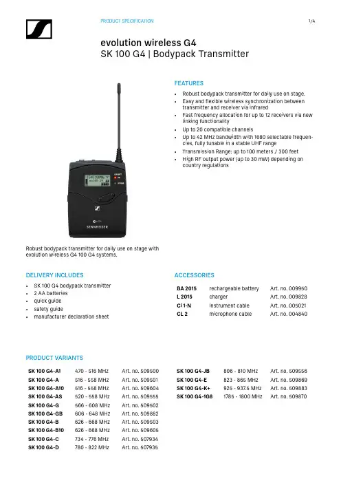
FEATURES• Robust bodypack transmitter for daily use on stage.• Easy and flexible wireless synchronization betweentransmitter and receiver via infrared • Fast frequency allocation for up to 12 receivers via newlinking functionality • Up to 20 compatible channels• Up to 42 MHz bandwidth with 1680 selectable frequen-cies, fully tunable in a stable UHF range • Transmission Range: up to 100 meters / 300 feet • High RF output power (up to 30 mW) depending oncountry regulationsDELIVERY INCLUDES• SK 100 G4 bodypack transmitter • 2 AA batteries • quick guide • safety guide• manufacturer declaration sheetRobust bodypack transmitter for daily use on stage with evolution wireless G4 100 G4 systems.ACCESSORIESBA 2015rechargeable battery Art. no. 009950L 2015chargerArt. no. 009828Ci 1-N instrument cable Art. no. 005021CL 2microphone cableArt. no. 004840PRODUCT VARIANTSSK 100 G4-A1470 - 516 MHz Art. no. 509500SK 100 G4-A 516 - 558 MHz Art. no. 509501SK 100 G4-A10516 - 558 MHz Art. no. 509604SK 100 G4-AS 520 - 558 MHz Art. no. 509555SK 100 G4-G 566 - 608 MHz Art. no. 509502SK 100 G4-GB 606 - 648 MHz Art. no. 509882SK 100 G4-B 626 - 668 MHz Art. no. 509503SK 100 G4-B10626 - 668 MHz Art. no. 509605SK 100 G4-C 734 - 776 MHz Art. no. 507934SK 100 G4-D780 - 822 MHzArt. no. 507935SK 100 G4-JB 806 - 810 MHz Art. no. 509556SK 100 G4-E 823 - 865 MHz Art. no. 509869SK 100 G4-K+925 - 937.5 MHz Art. no. 509883SK 100 G4-1G81785 - 1800 MHzArt. no. 509870SPECIFICATIONSRF characteristicsModulation Wideband FM Frequency ranges A1: 470 - 516 MHzA: 516 - 558 MHzA10: 516 - 558 MHzAS: 520 - 558 MHzG: 566 - 608 MHzGB: 606 - 648 MHzB: 626 - 668 MHzB10: 626 - 668 MHzC: 734 - 776 MHzD: 780 - 822 MHzJB: 806 - 810 MHzE: 823 - 865 MHzK+: 925 - 937.5 MHz1G8: 1785 - 1800 MHz Transmission frequencies Max. 1680 receivingfrequencies, adjustable in25 k Hz steps20 frequency banks, eachwith up to 12 factory-presetchannels, no intermodula-tion1 frequency bank with up to12 programmable channels Switching bandwidth up to 42 MHzNominal/peak deviation±24 kHz / ±48 kHz Frequency stability≤ ±15 ppmRF output power at 50 ΩMax. 30 mWPilot tone squelch Can be switched off AF characteristicsCompander system Sennheiser HDXAF frequency response Mic: 80 – 18,000 HzLine: 25 – 18,000 Hz Signal-to-noise ratio (1 mV,peak deviation)≥ 110 dBATotal harmonic distortion(THD)≤ 0.9 %Max. microphone/lineinput voltage3 VeffMicrophone/lineinput impedance40 kΩ, unbalanced / 1 MΩInput capacitance SwitchableSetting range for inputsensitivity60 dB,adjustable in 3 dB steps Overall deviceTemperature range-10 °C to +55 °CPower supply 2 AA batteries, 1.5 V orBA 2015 accupack Nominal voltage 3 V battery /2.4 V rechargeable battery Current consumption at nominal voltage:typ. 180 mAwith transmitter switchedoff: ≤ 25 µAOperating time Typically 8 h Dimensions Approx. 82 x 64 x 24 mm Weight (incl. batteries)approx. 160 gDIMENSIONS3,5mm Klinke 3,5mm plugARCHITECT‘S SPECIFICATIONThe compact bodypack transmitter shall be for use with a companion receiver as part of a wireless RF transmission sys-tem.The transmitter shall operate within twelve UHF frequency ranges, with a switching bandwidth of up to 42 MHz: 470 – 516 M Hz, 516 – 558 MHz, 520 – 558 MHz, 566 – 608 MHz, 606 – 648 MHz, 626 – 668 MHz, 734 – 776 MHz, 780 – 822 MHz, 823 – 865 MHz, 806 – 810 MHz, 925 – 937.5 MHz, 1785 – 1800 MHz; transmission frequencies shall be 1,680 per range and shall be tunable in 25 kHz steps. The transmitter shall feature 20 fixed frequency banks with up to 12 compatible frequen-cy presets and 1 user bank with up to 12 user programmable frequencies.The transmitter shall be menu-driven with a backlit LC display showing the current frequency, frequency bank and chan-nel number, metering of AF level, transmission status, lock status, pilot tone transmission, muting function, and battery status. An auto-lock feature shall be provided to prevent settings from being accidentally altered.The transmitter parameters shall either be configurable in the associated receiver’s menu and synchronized with the transmitter via an integrated infrared interface or shall be programmable in the transmitter menu.The transmitter shall be equipped with a mute switch, which shall be switchable between “AF on/off”, “RF on/off” and “Disabled” via the user interface.Nominal/peak deviation shall be ±24 kHz/±48 kHz. Frequency stability shall be ≤ ±15 ppm. RF output power at 50 Ω shall be 30 mW (typical).The transmitter shall incorporate the Sennheiser HDX compander system and a defeatable pilot tone squelch. Audio fre-quency response shall range from 80 – 18,000 Hz (microphone) or 25 - 18,000 Hz (line). Signal-to-noise ratio at 1 mV and peak deviation shall be ≥ 110 dBA. Total harmonic distortion (THD) shall be ≤ 0.9 %. Input sensitivity shall be adjustable within a 60 dB range in steps of 3 dB.Power shall be supplied to the transmitter by two 1.5 V AA size batteries or by one Sennheiser BA 2015 rechargeable accupack. Nominal voltage shall be 2.4 V for a rechargeable battery or 3 V for a battery, current consumption shall be typical 180 mA at nominal voltage; ≤ 25 µA when transmitter is switched off. Operating time shall be typical 8 hours. The transmitter shall have a rugged metal housing; dimensions shall be approximately 82 x 64 x 24 mm (3.23" x 2.52" x 0.94"). Weight including the batteries shall be approximately 160 grams (0.35 lbs). Operating temperature shall range from−10 °C to +55 °C (+14 °F to +131 °F).The transmitter shall be the Sennheiser SK 100 G4.Sennheiser electronic GmbH & Co. KG · Am Labor 1 · 30900 Wedemark · Germany · 。
SCR100用户手册版本:1.1版日期:2009年12月内容介绍本文档主要介绍SCR100产品的安装注意事项及连线方法,并简要介绍了考勤软件的相关操作。
重要申明首先感谢您选择我公司的产品。
在使用前,请您仔细阅读本产品的说明书。
以避免设备受到不必要的损害!本公司提醒您正确使用,将得到良好的使用效果和验证速度。
非经我公司书面同意,任何单位和个人不得擅自摘抄、复制本手册内容的部分或全部,并不得以任何形式传播。
本手册中描述的产品中,可能包含我公司及其可能存在的许可人享有版权的软件,除非获得相关权利人的许可,否则,任何人不能以任何形式对前述软件进行复制、分发、修改、摘录、反编译、反汇编、解密、反向工程、出租、转让、分许可以及其他侵权软件版权的行为,但是适用法禁止此类限制的除外。
由于产品的不断更新,我公司不能承诺实际产品与该资料一致,同时也不承担由于实际技术参数与本资料不符所导致的任何争议,任何改动恕不提前通知。
目录1.使用须知 (1)1.1 产品功能简介 (1)1.2正面图 (1)1.3安装注意事项 (2)1.4系统安装示意图 (4)1.5通讯连接示意图 (5)2.安装 (6)2.1固定后盖板 (6)2.2连接外围设备 (7)2.2.1门磁连接线 (8)2.2.2出门按钮连接线 (8)2.2.3报警器连接线 (9)2.2.4门锁连接线 (9)2.2.5 以太网连接线 (13)2.2.6 RS232连接线 (14)2.2.7 RS485接口线 (15)2.2.8 Wiegand输出连接线 (16)2.2.9 电源连接线 (17)2.3 固定设备 (18)2.4安装后的检查 (18)3. 考勤软件简介 (19)3.1 登记设备 (19)3.2登记用户和ID卡 (20)3.3 上传和下载 (22)3.3.1 上传到设备 (23)3.3.2 下载到电脑 (24)3.4实时监控 (24)4. 其它 (26)4.1复位键 (26)4.2防拆开关 (27)1. 使用须知1.1 产品功能简介SCR100是中控科技推出的全球第一款基于TCP/IP 的门禁控制器和读头,射频卡无屏无按键专业门禁机,增加射频卡类门禁产品系列,为系统门禁方案提供更多的产品选择,该产品即可作为一体机单独控锁,也可以作为门禁控制器连接射频卡门禁读头使用,实现主从机或者反潜功能,标准的TCP/IP 协议可实现跨网段、跨网关连接组网,可内置Webserver 通过网络访问查询记录等。

SmartKey Access Controller Manual SK100系列单门控制器手册目录第一章1、SmartKey SK100单门控制器1、1简介1、2系统构造1、2、1控制器1、2、2读卡器1、2、3门磁开关1、2、4电控锁1、2、5其他输入/输出设备1、2、6电源1、2、7与PC机相连1、2、8卡片第二章2、安装2、1接线图2、1、1LED指示灯2、1、2终端电阻2、2读卡器的安装2、3电控锁、门磁和出门按钮的安装2、3、1电控锁的安装2、3、2门磁2、3、3出门按钮2、4其他输入/输出设备的安装2、5电源2、6与PC机联网工作2、7控制器多阶层通讯方式2、8给控制器通电第三章3、控制器的设置3、1设置控制器的ID地址3、2 在控制器中增加、删除一张卡片3、3 门的互锁设置3、4 门磁常态值设定3、5 通讯波特率的设定3、6 控制器时间设定和调整3、7 控制器内存的动态调整3、8 修改控制器的登录密码3、9 同卡延时时间设置3、10 删除控制器的全部记录第四章3、功能特点及技术参数3、1技术指标3、2功能特性第五章4、故障及排除4、1控制器为什么会不在网?4、2刷卡后为何不能开门?4、3通电状态下读卡器为什么不能读卡?4、4控制器LCD显示乱码第六章5、结束附录一控制器接线图附录二布线施工规范第一章1、Smartkey SK100单门控制器1、1 简介本手册讲述了SK100单门控制器安装及使用规范。
控制器必须由专业人员进行安装及操作。
SK100单门控制器是基于16位单片机开发而成的、具备许多先进特性的新一代智能控制器。
我们希望你能够细心阅读本手册以便你能感受到此系统的全部特性,并能在安装和使用过程中正确操作。
SK100单门控制器具有人性化的功能菜单介面,操作简单,功能强大。
本手册适合SK100, SK100E和SK100M型号的控制器1、2 系统构造首先有必要解释一下SK100单门控制器以及本手册频繁用到的一些基本名词。

PLS-K-100升级版产品手册Product ManualsVersion 2.0中英文版CN&EN上海派欧机电设备有限公司Shanghai Paiou Electrical & Mechanical Equipment Co. LTD目录一、产品概述Product overview ............................. 错误!未定义书签。
二、性能指标Technical Parameter ......................... 错误!未定义书签。
三、尺寸图Technical Parameter ............................. 错误!未定义书签。
四、接口Interface .................................................. 错误!未定义书签。
五、通信协议与传输方式Communication Protocol and Output Format错误!未定义书签5.1端口配置USART Interface .......................... 错误!未定义书签。
5.2控制流字符Control flow char (8)5.3 命令Command Frame ............................... 错误!未定义书签。
5.4命令Commands (10)5.5测量模式Measure Modes (17)5.6状态码Status Codes (17)六、示范Demonstration (18)6.1连接到USB2TTL转换器............................. 错误!未定义书签。
6.2串口测试软件............................................. 错误!未定义书签。
七、联系我们Contact us ........................................ 错误!未定义书签。


_1_减速机操作手册B 1010_1040_CN 重要提示..............................................2 适用范围..............................................3 安全须知..............................................41 减速机型号及附件......................................5 1.1 NORD 减速电机型号举例说明.........................5 1.2 减速电机的铭牌....................................62 设备的运输及储存......................................7 2.1收货及检验 ........................................7 2.2设备的搬运 . (7)2.3设备的储存 (8)3 设备的安装............................................9 3.1安装前的准备和检验 .. (9)3.2减速电机的安装 (10)3.3 减速机空心轴的安装...............................12 3.4 扭矩臂的安装.....................................13 3.5空心轴锁紧盘的安装 . (14)3.6 IEC 标准电机的连接................................16 3.7逆止器的连接 . (17)3.8电机的连接 (18)4 电气接线.............................................195 设备的运行...........................................23 5.1 检查油位.........................................23 5.2 激活IEC 适配器自动补油杯.........................24 5.3 减速机效率.......................................25 5.4 检查减速电机.....................................25 5.5 自检项目清单.....................................266 减速机的维修与保养...................................27 6.1 维修与保养.......................................27 6.2 减速电机的全面维修保养...........................29 6.3 润滑油的注油量...................................30 6.4 润滑油的品牌表...................................377 常见故障现象及分析...................................38附件一、安装位置表..................................... 39附件二、零件清单........................................45附件三、螺栓力矩........................................58附表一 减速机各形式及附件的代号与含义...................59附表二 电机各形式及附件的代号与含义.....................60 _2_减速机操作手册B 1010_1040_CN重要提示① 本操作和维护手册(以下简称手册)是减速电机供货不可缺少的组成部分。

Infrared thermometer KIRA Y 100 with dual laser sighting is a key tool to diagnose, inspect and check any temperature, with the advantage of using “no-contact” technology. You can safely measure surface temperatures of hot objects, dangerous or difficult to access. Perfect tool to take temperature in a house, a garage, a workshop, an office, a car, a kitchen etc...Spectral response ..................8 - 14 µmOptical .....................................D.S : 20:1 (13 mm at 260 mm)Temperature range .................From -50 to +800°CAccuracy*...............................From -50 à +20°C : ±2.5°CFrom +20 to +300°C : ±2% of reading ±2°C From +300°C to +800°C : ±2% of readingInfrared repeatability ..............From -50 to +20°C : ±1.3°CFrom +20 to +800°C : ±0.5% or ±0.5°CDisplay resolution ..................0.1°C Response time .......................150 msEmissivity ...............................Adjustable from 0.10 to 1.0 (pre-set at 0.95)Over range indication ............Display indication : « ---- »Dual laser sighting .................Wave length : from 630 nm to 670 nmOutput < 1mW, Class 2 (II)Positive or negativetemperature indication ................Automatic (no indication for a positivetemperature)(-) sign for a negative temperatureDisplay ....................................4 digits with LCD backlighted display Auto-extinction .......................Automatic after 7 seconds of inactivity High/low alarm .......................Flashing signal on display and beep signalwith adjustable thresholdsPower supply ..........................Alkaline 9V batteryAutonomy ...............................105 h (inactive laser and backlight)20 h (active laser and backlight)Use temperature .....................From 0 to +10°C for a short periodFrom +11 to +50 °C for a long periodStorage temperature ..............From -10°C to +60°CRelative humidity ...................From 10 to 90%HR in operating modeand > 80%RH in storageDimensions .............................145 x 95 x 40 mmWeight .....................................180 g (included battery)Make sure that the target is larger than the size of the laser sighting.Technical featuresDistance from the targetKIRAY 100Infrared thermometerDistance Diameter 254260508mm 12.71325.4mmD:S=20:113 mm at 260 mmYES NO*Accuracy for an ambient temperature from 23 to 25°C (with a relative humidity lower than 80% RH)Kimo KIRAY 100 Infrared Thermometer1 – Up button. It allows to increment emissivity and high/low alarm thresholds.This button also allows in measurement mode to activate or deactivate the laser.2 – Mode button. It allows to navigate through the modes (emissivity, lock, high alarm, low alarm).3 – Down button. It allows to decrement emissivity and high/low alarm thresholds.This button also allows in measurement mode to activate or deactivate thebacklight.123Battery compartmentTriggerDescriptionSet technical unit (°C/°F)LCDbacklighted display Up buttonMode buttonDown buttonIR sensor(infrared)KIRAY 100 buttons1 – Technical unit °C/°F2 – Low battery indicator3 – Emissivity value = 0.95 (factory setting)4 – Max temperature indicator.5 – Temperature value6 – Current measurement indicator7 – HOLD indicator (fixed measurement)8 – Laser in operation indicator9 – Lock indicator (continuous measurement)10 – High alarm symbol (fixed : activated alarm ; flashing + beep : alarm thresholds exceeded)11 – Low alarm symbol (fixed : activated alarm ; flashing + beep : alarm thresholds exceeded)Display●Case with passer-by belt ●User manualCE CertificationThis device meets with following standards' requirements.EN 50081-1 : 1992, Electromagnetic compatibility, Part 1EN 50082-1 : 1992, Electromagnetic compatibility, Part 2Infrared thermometer, how does it work ?Infrared thermometers canmeasure the surfacetemperature of an object. Its optic lens catches the energy emitted and reflected by the object. This energy is collected and focused onto a detector. This information is displayed as temperature. The laser pointer is only used to aim at the target.Laser sighting Infrared sensorEmitted energy by theobject as radiationSupplied withOutput laser sighting。

(2) Function edit interface 2) Motor parameter setting optionsSet up the motor speed and movement direction.Time Lapse Mode1 Setting interfaceSpacing Distance: sets the interval running distanceInterval Time: sets the interval time between each shotsRun Distance: sets the total running distanceShot: sets the total number of shots.4) Live Motion ModeLive Motion mode: includes Manual Mode and Auto modeManual Mode: for manual operationAuto mode: for automatic movementAuto Mode setting interfaceJoystick Center→Start/Stop:starts or stops running when you press the joystick(When restart, the running direction for sliding plate is the same asprevious time, also the sliding plate will continue the back and forthmovement until it reaches the next instruction.)Mount the camera equipped with quick-release plate onto sliding plate.Connect the rail sliding palte with camera by using camera cable. Turn onthe camera and adjust it to automatic mode. Choose “Time Lapse Time2"mode on the remote control, press “Interval" using the up-downbutton and see the words flashing. Adjust to left and right using thejoystick. Set an appropriate value and press “ok". Press “Rec Time"using the up-down button and see the words flashing. Adjust to the leftand right using the joystick. Set an appropriate value. Exit and press “Start"to check whether the camera take photos according to the values you set.When the blue 2.4GHz indicator l ights up and the display screen showsoperation interface, the remote controller succeeded to connect withSelect "Motor Set" using the up-down buttons, press "ok" to enter "MotorSet"menu, press "ok" and choose SPEED, press "+/-" to adjust speed (thelarger the value, the faster the speed) to fastest and then exit "Motor Set"menu. Select "Live Motion Mode", press "ok" to enter the menu, choose"Manual Mode" and enter the menu. Move the joystick to check if thesliding plate moves well or not.。
SK100 ACCESS CONTROL SYSTEM TECHNICAL MANUAL产品技术手册V ersion 2.0对本手册所包含的所有信息,包括URL链接和其他网上资料,本公司有权未经通知,自行修改。
所举例引用的公司名称、组织机构、产品、人名以及事件,均与任何真实公司名称、组织机构、产品、人名和事件无关。
用户应遵守所有知识产权保护法律。
本手册任何部分在未经Singapore SmartKey Technology International Private Limited书面同意的情况下,不得以任何形式(电子媒体、影印、记录或其他)再版、存储或引用。
手册中提到的所有其他产品,其知识产权均为其相关拥有者所具有。
© 2005 Singapore SmartKey Technology International Private Limited.版权所有此产品符合欧洲以下标准:EMC Directive: 89/336/EEC目录1. SmartKey SK100系列控制器 (1)1.1简介 (1)1.2系统构成 (1)1.2.1 SK100单门控制器 (1)1.2.2读卡器 (1)1.2.3 门磁 (3)1.2.4 电控锁 (3)1.2.5 开门按钮 (4)1.2.6 其它输入/输出设备 (4)1.2.7电源 (4)1.2.8 与PC机相连接 (4)2. 安装 (5)2.1 SK100系列控制器接线图 (5)2.1.1控制器上的指示灯 (5)2.1.2 终端电阻 (5)2.2 与读卡器的连接 (7)2.3 与电控锁相连接 (8)2.4 与门磁的连接 (8)2.5 与开门按钮的连接 (9)2.6 与其它输入/输出设备的连接 (9)2.7 与电源的连接 (10)2.8 与PC机的连接 (11)2.9 控制器多阶层通讯方式 (12)2.10 给控制器通电 (13)3. 菜单操作 (13)3.1 系统菜单 (13)3.1.1 初始化系统 (14)3.1.2 设置控制器的ID地址 (14)3.1.3修改登录密码 (14)3.1.4 删除所有记录 (14)3.1.5 动态调整 (14)3.1.6 设置同卡延迟时间 (14)3.1.7 设置波特率 (15)3.1.9 修改安全密码 (15)3.1.10 设置键盘开门 (15)3.1.11 设置防尾随 (15)3.2 时间菜单 (15)3.2.1日期设置 (16)3.2.2 时间设置 (16)3.2.3 校正时间误差 (16)3.2.4 设置继电器定时 (16)3.2.5 设置时段 (17)3.2.6 设置时区 (17)3.2.7 设置时区表 (17)3.2.8 假日设置 (18)3.2.9 设置群组 (19)3.3 读卡器菜单 (19)3.3.1 设置读卡器的控制方向 (19)3.3.2 设置动作模式 (20)3.4 卡片菜单 (20)3.4.1 感应加卡 (20)3.4.2 位置码加卡 (20)3.4.3 感应删除卡片 (20)3.4.4 删除全部卡片 (21)3.4.5 位置码删卡 (21)3.4.6 按卡片序号删卡 (21)3.4.7 依群组增加卡片 (21)3.5 门菜单 (21)3.5.1设置返潜回 (22)3.5.2 设置开门时间 (22)3.5.3 自动开门时区表 (22)3.5.4 设置密码取消时区表 (22)3.5.5 设置多卡认证 (22)3.5.6 设置互锁 (22)3.5.7设置密码开门时区表 (23)3.5.8 设置门磁的常态值 (23)3.5.9 设置报警输出 (23)3.6 高级菜单 (23)3.6.1 重置反潜回 (24)3.6.2 设置报警键 (24)3.6.3 设置卡号输出字节 (24)3.6.4 设置卡号显示方式 (24)3.7 查询 (24)3.7.1 控制器ID号 (24)3.7.2 控制器层级 (25)3.7.3 控制器序列号 (25)3.7.4 卡片数量 (25)3.7.5 记录数量 (25)3.7.6 软件版本号 (25)3.7.7 同卡延迟时间 (25)3.7.8 卡片最大存储量 (25)3.7.9 记录最大存储量 (25)3.7.10 监控通讯状态 (25)3.8 开门命令 (26)3.8.1 键盘开门 (26)3.8.2 密码开门 (26)3.9 菜单一览表 (27)附录1 电缆规格 (29)附录2 电源规格 (30)附录3 控制器后盖安装尺寸 (31)SK100系列控制器说明书1. SmartKey SK100系列控制器1.1简介本手册讲述了SK100控制器安装及使用规范。

目录1.一般安全措施general safety measures (1)2.安装设置installation settings (1)2-1运输注意事项Transportation notice (1)2-2组装场所Assembly site (2)2-3配管piping。
(2)2-4电器配线Electrical wiring (3)3.运转操作Operation (3)3-1运转前检查项目Inspection items before operation (3)3-2控制操作Control operation (3)4.维修保养Maintenance (4)4-1清理Clear (4)4-2储存Storage (5)5.故障排除Trouble shooting (5)5-1渗漏leakage (5)5-2异常报警及排除Exception alarm and troubleshooting (5)1.一般安全措施在使用本冷却机前,请先详细了解这些安全要求。
使用本冷却机时请遵守这些安全要求以避免火灾、电击或人身伤害。
(1)维持工作区域干净并通风良好,杂乱或昏暗的环境易造成意外。
(2)不可在危险环境操作:请勿在潮湿、被雨淋或有潜在爆炸性的场所使用本冷却机。
(3)勿使儿童接近:所有非操作人员皆应在工作区域之外的安全场所。
(4)使用适当的电线:请使用可承受本冷却机额定电流且状况良好的电源线。
(5)请勿堆积物品在本冷却机上:请勿在冷却机上方放置任何物品,物品掉落容易造成人身伤害或机械损伤。
(6)更换电线前,请先将电源关闭。
(7)若有任何修理或更换零件时,请注意下列事项:(A)首先请将操作开关关闭,并切掉电源,再更换零件。
(B)若需要用到气焊的场合,请避免火直接碰到油或油气而产生火灾。
(C)若需要排放冷媒时,请在通风良好的场所排放,以免窒息。
2.安装设置本冷却机是为精密机械而设计的水冷却装置,它在精密机械上,能提供高精度的水温控制。

江苏省苏科仪表有限公司目录一、概述 (1)二、主要技术指标 (1)三、型号说明 (3)四、操作说明 (4)五、报警 (8)六、变送输出 (9)七、打印功能 (9)八、通讯说明 (10)九、举例 (11)十、端子接线 (13)十一、关于SK-600智能光柱调节仪的几点说明 (16)十二、常见故障处理 (17)江苏省苏科仪表有限公司一、概述SK-100智能测控仪是智能型、高精度的数显温度、压力、液位测量控制仪表,与温度、压力、液位传感器及变送器配接可构成各种量程和规格的温度、压力、液位测控系统。
SK-100智能测控仪的输入信号可通过内部微型继电器任意改变,输入端子只需3个就能满足热电偶、热电阻、0~10m A或4~20m A标准电流、0~5V、1~5V标准电压信号的要求。
主要特点:◆采用当今最先进的ATMEL单片微机作主机,减少了外围部件,提高了可靠性。
◆集多种输入型号、输出方式于一机。
◆采用W ATCHDOG电路、软件陷阱与冗余、掉电保护、数字滤波等技术,注重现场容错能力,使整机具有很强的抗干扰能力。
◆采用双四位LED数码显示,可同时显示测量值与报警点设定值。
二、主要技术指标:基本误差:0.2%FS±1个字分辨力:1、0.1显示:双四位LED数码管显示输入信号:标准电流0~10m A、4~20m A标准电压0~5V,1~5V热电偶K、S、B、T、E、J、WRE、N江苏省苏科仪表有限公司热电阻Pt100、Cu50、Cu100冷端补偿误差:±1℃报警输出:二限报警或四限报警,每个输出根据需要可设定为上限报警、下限报警或禁止使用,继电器输出触点容量AC220V/3A或AC220V/1A。
变送输出:4~20m A(负载电阻≤500Ω)、0~10m A(负载电阻≤1000Ω)1~5V、0~5V(负载电阻≥200KΩ)通讯输出:接口方式——隔离串行双向通讯接口RS485/RS422/RS232/Modem波特率——300~9600bps内部自由设定馈电输出:DC24V/30m A温度补偿0~50冷端温度自动补偿,误差:±1℃电源:开关电源85~265V AC功耗:4W环境温度:0~50℃环境湿度:<85%RH面板尺寸:160mm×80mm、96mm×96mm、96mm×48mm、72mm×72mm、48mm×48mm三、型号说明江苏省苏科仪表有限公司江苏省苏科仪表有限公司四、操作说明HA-HA报警灯LA-LA报警灯OUT-输出指示灯COM- 通讯指示灯AT-自整定状态灯PV-测量值显示窗SV-设定值显示窗(二)上电自检⑴按仪表的端子接线图连接好仪表的电源、输入、输出、报警等接线。
SK-A100激光测距传感器用户手册上海申稷光电科技有限公司Shanghai SenkyLaser Photoelectric Technology Co. LTD 版本:V2.0 日期:2021.1.4Version: V2.0 Date: 2021.1.4说明本文档用于指导用户使用SK-A100测距激光雷达。
文中介绍了产品性能、结构尺寸、通讯协议以及使用是注意的事项。
本文的解释权归上海申稷光电科技有限公司所有。
本文档可能与所销售最新产品版本存在差异,具体以销售工程师提供的解释为准。
文档中如果存在不清楚的地方,请联系对应销售,或者联系邮箱*****************.目录1.产品概述Product overview (4)2.性能参数 Performance parameters (5)3.关键指标Key index (6)4.机械参数Mechanical parameters (7)5.输出接口Output interface (8)6.通讯协议Communication protocol (9)RS232通讯协议 (9)RS485 自由协议 (10)RS485 RTU标准协议 (13)电流环4-20mA (13)0-5V电压信号 (13)7.注意事项Matters needing attention (14)7.1影响因素 Influence Factor (14)7.2安全注意事项 Safety Precautions (15)8.上位机调试指南Debugging guide (16)1.产品概述Product overviewSK-A100激光测距传感器采用激光相位法测距原理。
可以通过激光的发射和接收,以非接触方式快速而准确的测量到自然目标之间的距离值。
将SK-A100激光测距传感器固定一个位置,开始工作后,可以快速发射一束可见红色激光,测到目标物后激光漫反射信号被传感器接收镜头接收信号;光速一定的前提下,相位法精确计算发射接收的时间差,即刻快速获取目标物到传感器之间的距离值。
The KISS -100 is a full featured compact table top unit and by far the lowest cost automated selective solder-ing machine available. The PCB and through hole com-ponents are automatically fluxed and soldered using the proven ‘traveling mini–solder wave” soldering process.The KISS -100 includes the following:Standard Features:∙ Will process PCBs 12” x 12” (300mm x 300mm) and up to 24” (600mm) long PCBs using a manual “step over” ∙ Universal PCB location rails with multiple PCB positions ∙ Automated Fiducial Correction∙ Windows 7 O/S with SWAK programming interface∙ Programming camera (used for manual fiducial location) ∙ Rapid setup time to “first production” using the machine “teach” functions or available Offline programming∙ Step and repeat capability in both X and Y axis for multiple boards in a panel∙ Lead alloy solder pot and pump assembly included—lead free alloy (all titanium) and HMP alloy pot and pump avail-able∙ Programmable solder wave flow rate ∙ 6mm and 12mm “Bullet” nozzles ∙ Heated Nitrogen to the solder nozzle∙ Precision KFS -SP atomizing flux applicator∙ Set the time/temp profile for each individual component type for maximized process control and TAKT∙ Absolute control over all critical process parameters:- Solder temperature interlocked to within 10°C - Height and travel speed of the solder wave - Programmable initial pre -heat soak time ∙ Set -up kit containing all necessary support tools∙ One year warranty covering the entire machine and two years for the solder pot and pump assemblyAdvantages:Simple and Affordable…..The KISS -100 is used to solder through hole components on SMT boards within close proximity of adjacent compo-nents. This process overcomes the limitations and high labor costs of operator dependent soldering with a truly flexible automated flux application and molten solder deliv-ery system.The KISS -100 couples high throughput with precise pro-cess controls. The programmable features provide the tools to set all process parameters including solder height, flux speed, solder temperature, panelization programming, contact dwells, travel distances and speeds.. Once set, the system will repeat precisely.The KISS -100 will out produce 3 or more operators solder-ing with an iron while significantly increasing the solder joint quality and to a predictable schedule.“You can expect a ROI of 2-3 months or less”Process Overview:The operator places the components into the PCB, then the PCB is placed onto the universal PCB location rails. The cycle is started by pressing the dual green buttons. The Automated Fiducial Correction identifies the start point. Flux is automati-cally applied to the solder sites. The mini solder wave is moved under the component to be soldered. The solder noz-zle raises to “wet” the first pins. The solder wave travels the length of the component soldering the through hole leads to the PCB. At the completion of the travel the solder pot lowers and moves to the next site. All programmed sites are fluxed and soldered in the same cycle. An automated stepping func-tion allows solder arrays of boards in an X -Y matrix. After completing the cycle the pot can be programmed to return to the start position ready for the next cycle.ACE Production Technologies , Inc.3010 N. First Street, Spokane Valley, WA 99216 (509) 924-4898 l http:/www.ace ModelKISS -100“Keep It Simple Soldering”12” x 12” PCB Platform(300mm x 300mm)Made in AmericaACE Production Technologies, Inc.3010 N. First Street, Spokane Valley, WA 99216 (509) 924-4898 l http:/www.ace KISS -100 on the optional supportbenchSet the zero point, then choose the flux width and solder nozzle and “paint” the process paths. It is that easy……….Programming:The programming is accomplished by one of two methods; on the machine or with the optional Offline Teach program-ming interface software. On the machine uses the set up camera viewed on the monitor and point -and -click method to set the flux and solder pattern in real time. Usually an average board can be programmed within 10 minutes. You can fine tune the X,Y and Z positions, speeds, solder wave height and other parameters to perfect the process.Optionally, at your desktop import a JPEG (photo) or the Gerber file into the SWAK program. Pick the solder nozzle size (this becomes your curser). Choose the start/stop po-sitions for all devices to be soldered. The process path becomes highlighted and script is automatically created for you. Circular or angular interpolation allows the soldering of large round arrays in a spiral pattern and connectors not perpendicular to the X -Y plane (see the SWAK data sheet and video).Programming the flux pathsApplyingthe flux Programming the solder pathsSoldering thecomponentsOptions:∙ Additional solder pot/pump assemblies for Pb, Sn or HMP alloys∙ Additional “Bullet” or “Wave” solder nozzles and W -75mm wide wave nozzle for mass wave soldering ∙ Process witness camera∙ Offline programming software∙ Support bench (required for 220V)∙ Universal PCB location rack with adjustable fingers to hold the PCB in position suitable for processing∙ Skyhook fixture which fits on the PCB location rails and has adjustable ‘hook’ for pulling the bow from the PCBKISS -100 Specifications:PCB Panel Size Minimum Maximum 2” x 2” 12” x 12”(50mm x 50mm) (300mm x 300mm)(can handle PCBs up to 24” x 12” (600mm x 300mm) with manual slide over)Safe “Keep Away” (distance to adjacent pads) 1mmMotion ∙ Z -Axis Accuracy/Repeatability +/-.002" Speed .5 inches per second ∙ X and Y Axis Accuracy/Repeatability +/-.002"Speed 1 inch per second Solder Pot∙ Temperature PID proportioning (0-400°C) ± 2°C ∙ Solder Capacity 30 lbs. (14kg) ∙ Pump PC controlledSoftware Windows 7 O/S and SWAK programming interface Physical ∙ Dimensions machine only: 41" wide x 38" deep x 32" high (1041mm wide x 965mm deep x 812mm high) w/support bench: 60" wide x 41" deep x 59" high (1524mm wide x 1041mm deep x 1498mm high) ∙ Weight machine only: 400 lbs. (180 kg) w/support bench: 700 lbs. (317 kg) ∙ Load height on bench 44" high (1117mm high)Facilities∙ Power Domestic 120VAC/1 Ph/60 Hz 15 ampsInternational 208-230VAC/1 Ph/60 Hz 8 amps ∙ Air 90 (minimum) to 100 (maximum) PSI ∙ Nitrogen 99.999% pure, 30-50 CFH @ 60(minimum) to 100 (maximum) PSI。
SK100产品手册Product Manuals Version1.0中英文版CN&EN上海申稷光电科技有限公司Shanghai Senky Photoelectric Technology Co.LTD目录一、SK100产品概述Product overview (4)二、性能参数Technical Parameter (5)三、外形尺寸Technical Parameter (6)四、接口Interface (7)4.1供电 (7)4.2通信线路 (7)五、通讯协议与传输方式Communication Protocol and Output Formt85.1端口配置Port Configuration (8)5.2协议Communication Agreement (8)5.3错误代码Error Code (9)5.4数据解析方式 (9)六、注意事项Matters Needing Attention (11)6.1影响因素Influence Factor (11)6.2安全注意事项Safety Precautions (12)6.3责任范围Scope of Liability (13)6.4重大使用危险Major Operational Risk (14)七、联系我们Contact us (15)订货号型号供电信号其他参数1000006SK100 3.3V TTL常温1000007SK100 3.3V TTL高低温款一、SK100产品概述Product overviewSK100激光测距模块为我司研发的高精度测距模块,具有测量精度高,测量速度快,安装操作简单等特点。
已广泛用于家装测量,工业控制等各领域。
模块安装和使用前请仔细阅读安装和操作相关章节,防止损坏模块。
产品特点:体积小巧重量轻测距距离远,可达100m精度高,最高可达1mm耐高低温-40~+60℃,常温款0-40℃二、性能参数Technical Parameter型号model SK100室内量程Indoor range0.03-100m室外量程Outdoor range0.03-30m输出频率output frequency2Hz重复精度accuracy2mm绝对精度Absolute accuracy±2mm分辨率resolution1mm盲区Blind area3cm光源Light635nm,<1mW,红色激光,二类安全激光通讯接口Communication interface UART TTL串口电平Serial level V TTL=3.3V工作温度Operating temperature 0-40℃(常温款)-40-+60℃(高低温款)工作电压Working voltage DC+3.3V 工作电流Working current80mA 功率Power0.27W 体积volume72*40*18mm 重量weight21g三、外形尺寸Technical Parameter四、接口Interface正确的接入电源和通信链路,是保证模块正常工作的前提条件,错误的接入操作可能会导致模块工作异常,甚至损坏。