快压机操作指示-4-3
- 格式:doc
- 大小:129.50 KB
- 文档页数:7

得宝机器的操作代码及错误代码 E001 主电机(M1)不正常;主电机基板装置不正常;主基板装置不正常;编码传感器(PS7)不正常当印鼓旋转指示灯亮,编码传感器;(PS7)在1秒内不能检查边缘 E002 升降电机(M2)不正常;升降上限传感器(PS9)不正常;升降下限传感器(MS6)不正常;驱动基板不正常;主基板不正常;升降机运作不正常当升降电机(M2)向上运动在9秒内升降机不能到达上限自检信息指示灯亮当升降电机(M2)向下运动在9秒内升降机不能到达下限自检信息指示灯亮 E003 裁切电机(M5)不正常;在操作侧(MS1)上的裁切限位不正常;在非操作侧(MS2)的裁切限位不正常;驱动基板不正常;主基板装置不正常;蜡纸在裁切装置部分卡纸裁切电机在裁切电机驱动信号发出3秒内不能到达可移动裁切刀的限位开关自检指示灯亮 E004 组合指示灯不正常;变压器装置不正常;CCD不正常;AD基板不正常;主基板不正常组合灯亮度检测,由CCD接收的光量不能到达规定值(只履行一次光量检查,电源闭合) E005 油墨滚筒升\降电机不正常电机在油墨滚筒升\降电机驱动信号送出15秒内不能触及相关开关 E006 触压电机不正常送出触压电机旋转指示令后25秒内,电机未能触及相关开关 E008 1\F基板装置不正常;IPC1\F基板装置不正常;在在线制版时,主基板装置和1\F基板装置之间出现信息错误 E009 直流稳压电源不正常;热敏头基板不正常;热敏头不正常开始制版时,热敏头驱动电压没有达到规定值 E201 ADF出故障 E301 A分类机传送电机出故障 E302 A分类机箱装置出故障E303 B分类机传送电机出故障 E304 B分类机箱装置出故障 E305 分类机桥电路电机故障 E306 A分类机订书机出故障 E307 B分类机订书机出故障得宝DP一体机操作代码序号分类说明 00 版本显示 ROM版本显示 01 功能检测滚筒转速显示/调节排纸带速/油墨滚筒升降电机动作/触压开关操作 03 动作检测纸带分组器动作检测 04 动作检测补充油墨 SP05 传感器和开关显示排版\天地限位\天地中心\原稿盖板\返回位置的各传感器用[0][1]或2位数值表示传感器状态印刷键:按下此键表示[显示1],释放此键[显示2] 显示1 [ **] 卸版传感器的接收光量(PS3 [00]—[63 无蜡纸≤45 有蜡纸≥无蜡纸时的值 PS05 显示2 [****] 天地限位传感器(PS10)遮光=1 天地中心传感器(PS11)遮光=1 原稿压板传感器(PS2)遮光=1 停止位置传感器(PS1)遮光=1 SP06 传感器开关显示 A/C模式传感器\B方式检验传感器\编码器\压印辊传感器\滚筒停止\堵纸传感器\着版、卸版位置传感器\卡纸\印鼓停止位置,卡纸位置检测传感器原稿方式键:文字方式键显示传感器状态清单如下用0 和1 表示传感器状态按下印刷键,显示如下状况显示 1 [****] 编码检验(PS7) 0或1 每读8次在0和1之间转换升降机上限传感器(PS9)遮光=1 A/C方式检测传感器(PS30)遮光=1 B方式检测传感器(PS30)遮光=1 如果按下印刷键并立刻松开,会出现下列状态显示2 [****] 印鼓蜡纸着版/脱版位置传感器(PS6)遮光=1 卡纸传感器接收光遮光=1 印鼓停止/卡纸检测位置传感器遮光=1 P滚筒传感器(PS7)遮光=1 原稿方式键下表为图像方式键显示状态如果按下印刷键并立即松开,会出现下列显示显示3 [****] 卡纸传感器接收光量 0----255 缺纸-----剩纸 07 传感器开关显示切刀限位开关(限位)\滚筒转动开关(有无转动)\版纸设置\纸开关\滚筒盖开关用0和1显示开关的状态印刷键:按下此键显示 [显示1],松开此键,出现[显示2] 显示1 [****] 滚筒旋转开关(SW3) PUSH=1 裁切刀限位开关(返操作侧)(MS2) PUSH=1 裁切刀限位开关(操作侧)(MS1) PUSH=1 [****] 前盖开关 SW (MS5)盖打开 =0 用纸开关SW(MS7) PUSH=1 升降下限开关SW(MS6) PUSH=0 蜡纸调节开关SW(SW4) PUSH=1 08 传感器开关显示扫描器\CCD传感器\接纸板检测开关(升降机下降)\卷芯满开关\给纸板设置开关\滚筒有无用0和1表示开关状态按下印刷键即可显示显示 [****] 滚筒检测开关 SW(MS4)滚筒检测=1 升降机下限开关SW(SW2) PUSH=1 卷蕊已满开关SW(MS8) PUSH=1 上盖开/关检测开关SW(MS2)盖子打开=0 09 动作检测DP2050=》》》滚筒停止位置检测 DP31===》蜡纸着版位置,卡纸检测位置,蜡纸脱版位置,印鼓停止位置 10 动作检测灯管\扫描电机运动检查 11 传感器开关显示原稿浓度值显示 12 动作检测 AD电路板存储 13 传感器开关显示末端标志传感器按下印刷键显示下列开关状态显示 [****] LO触压限位开关开=1 触压中心开关开=1 油墨滚升/降开关开=1 按下印刷键并立即松开,将会出现下列状态显示[**] 尾部标志传感器(PS3)的接收光量 00 63 14 总计数制版总数显示重新设置15 动作检测供墨电机运行检测 16 调整\说明联机制版时,制版开始位置的修正 17运行检测检测切刀电机运行 18 运行检测检测反转电机运行 19 总计数显示印刷总数,重新设置 20 运行检测检测版夹电机的运行及版夹夹紧位置 21 功能检测 ADF 功能检测 22 调整\说明在制版边纵向倍率补正量设定 23 调整\说明图象方式与原稿扫描暗度的确定 000 标准------001----010----011—100—101----110---111为最大 24 调整\说明印刷边纵向倍率修正量设定 000 标准------001----010----011—100—101----110---111为最大(1等级:0.25) 25调整\说明应用自动进稿器时,修正原稿基底的白色度 000 标准------001----010----011—100—101----110---111为最大 26 调整\说明修正图像方式下原稿浓度白基底的白色度 000 标准------001----010----011—100—101----110---111为最大 27 调整\说明将所有帮助程序进行初始化处理 28 调整\说明纸带分组器,蜂鸣器,磁卡计数器的设定 29 调整\说明调节蜡纸纵向进给长度(蜡纸头余量的调节 000 标准------001----010----011—100—101----110---111为最大 PS30 运行检测测试文本的制版和印刷===》》测试样张 31 调整\说明预印刷张数设定 0000(0张)------0001(1)----0010(2)----0011(3)->---1111(15张 32 调整\说明首张印速\卸版故障检测设置 *0** 第一张约45转 *1** JOG速度(15转 33 调整\说明文字方式白度补正 (原稿浓度白基底修正 000* ----*-001----*010----*011—*100—*101----*110-最大标准值---*111 35 调整\说明扫描器顶端的起始阅读位置 0***标准 ----1***----*000----*001—*010—*011----*100---*101--*110--*111 36 调整\说明扫描器纵向边(操作边)起始阅读位置 0***标准 ----1***----*000----*001—*010—*011----*100---*101--*110--*111 37 调整\说明应用扫描器时制版的起始位置 0***标准 ----1***----*000----*001—*010—*011----*100---*101--*110--*111 40 调整\说明当使用扫描器时,修正轮廓最亮处的浓度状态 41 调整\说明自动复位设置\重复计数显示42 调整\说明纸张选择规格设定 43 调整\说明热敏头电阻值设定 44 调节/参数调节设置热敏头电阻值级别的设定 45 调节/参数调节特殊用纸长度设定(下位4Bit)46 调节/参数设置特殊用纸长度设定(上位4Bit) 47 调节/参数调节特殊用纸宽度设定(下位4Bit) 48 调整\说明横向扫描时缩小量的调节 49 调整\说明读取侧中心倍率设定 50 调整\说明文字方式原稿读取浓度设定 51 调整\说明调整测试文本的制版浓度 52 调整\说明联机条件设定 53 调整\说明联机制版时横向(操作侧)制版开始位置调整 54 调节/参数调节主基板分类机功能检测 55 调整\说明油墨检测,切刀运转方式设定 56 调整\说明联机制版时,横向制版开始位置调整 57 调整\说明选择控制语言开关 59 末端传感器设置(图像档H--13) 60 调节/参数调节选择自动清除方式和良好启动方式 61 调节/参数调节显示参数 62 调节/参数设置显示选择的参数。
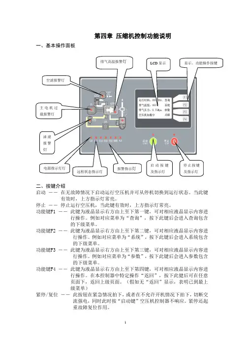
第四章 压缩机控制功能说明一、基本操作面板二、按键介绍启动 ――在无故障情况下启动运行空压机并可从停机切换到运行状态。
当此键有效时,上方指示灯常亮。
停止 ――停止运行空压机,当此键有效时,上方指示灯常亮。
功能键F1 ――此键为液晶显示右方由上至下第一键,可对相应液晶显示内容进行操作。
例如对应菜单为“查询”,按下此键后会进入查询包含的下级菜单。
功能键F2 ―― 此键为液晶显示右方由上至下第二键,可对相应液晶显示内容进行操作。
例如对应菜单为“系统”,按下此键后会进入系统包含的下级菜单。
功能键F3 ―― 此键为液晶显示右方由上至下第三键,可对相应液晶显示内容进行操作。
例如对应菜单为“参数”,按下此键后会进入参数包含的下级菜单。
功能键F4 ―― 此键为液晶显示右方由上至下第四键,可对相应液晶显示内容进行操作。
在本控制器中特定操作“返回”,按下此健后可在任意页面下,返回上级页面。
(假如无“返回”显示,表明已到最上级菜单)紧停/复位 ―― 此按钮在紧急情况拍下,或者在不允许开机情况下拍下,切断交流强电,同时此时按“启动键”空压机控制器不响应。
紧停还起重故障复位作用。
三、空压机操作使用介绍3.1 开机和主页面控制器通电后,操作面板上电源信号灯亮,STOP 灯亮。
屏幕显示开机页面(图4.1)欢迎使用螺杆空气压缩机图4.1五秒后系统自动进入缺省页面运行时间:00000Hr 查询排气温度:000℃系统排气压力:0.00MPa 参数空压机停机中功能图4.2缺省页面屏幕第一行为累计运行时间;第二行为排气温度值;第三行为排气压力值;第四行为运行状态和故障报警。
若空压机有故障则显示故障内容,若同时有多个故障则显示最先出现的故障。
故障排除后按紧停键复位显示。
若空压机有报警则交替显示报警状态和运行状态,若同时有多个报警则按优先级先后显示。
屏幕右边四个功能按键依次为:“查询”、“系统”、“参数”、“功能”。
“查询”功能键按下后可查看空压机当前的运行状态(比如温度,压力,电压,电流,时间等等。
远红外线收缩包装机的安全操作规程一、目的本规程编制的目的,是为了使每位操作员工都能严格按规定程序做事,熟悉机器设备的性能,以避免发生错误,保证安全生产。
二、适用范围本规程适用于采用使用远红外线的收缩包装设备。
三、操作要点1.合上侧热开关。
2.合上上热开关,调节上热旋钮至4档左右。
3.合上下热开关,调节下热旋钮至4档左右。
4.合上输送开关,调节输送旋钮至4-5档。
5.第一部操作完成后,让机器运转3分钟后再合上热风天并(实际操作中也可不开热风天关)。
6.放上已经装好收缩膜的物品,即可进行收缩色装。
7.在实际情况中如果收缩后皱纹过多,可减速低输送速度或提高加热速度,反之,如果出现过缩现象,则可减低温度。
8.包装结束后,先关闭三组加热开关,让输送电机和热风电机继续运行10分钟左右,再切断整个电源。
四、注意事项1、本机为两相220V电压,三脚插头,其中一条为机壳接地安全线,切勿将此线接入220V电压中。
2、本机共有九条加热管,二条作为侧热,加热时非常红亮。
三条上热,四条为下热,加热时亮度可调节。
3、本机一定要水平安装,否则容易走偏。
4、本机使用三个月以后,应检查收缩室内电线老化情况,酌情更换。
5、严禁在机器工作时把手伸入收缩室内,造成严重的烧烫伤。
喷码机的安全操作规程一、目的本规程编制的目的,是为了使每位操作员工都能严格按规定程序做事,熟悉机器设备的性能,以避免发生错误,保证安全生产。
二、适用范围本规程适用于公司的所有喷码设备。
三、作要点1、严格按使用说明书操作本设备。
2、切勿在喷码机附近吸烟或使用明火,喷码机使用的油墨和溶剂是易燃物质。
3、在进行清洁和维护之前,必须确保电源已断开,接通电源时,机箱和喷头上都有致命的高压。
(切勿取下喷码机机盖,机盖只能由有资格的维修工程师打开)。
4、溶剂具有潜在的危害油墨和深剂时,请配戴符合欧洲或国际有关指令要求的护目镜。
操作时,请配戴好安全眼镜与抗深剂的手套。
也可擦拭隔离霜,但在油墨溶剂可能接角到皮肤的情况下必须配戴抗溶剂的手套。

KD3800全自动液压压砖机使用说明书(机械部分)广东科达机电股份有限公司二零零一年五月目录一、总则二、机械概述三、安全说明四、安装过程五、操作规程六、维护与保养七.压制砖坯规格表八、用户自购备件明细表九.随机附件明细表附图一、压机外形图附图二、压机主体附图三、液压部阀组结构图附图四、布料装置结构图附图五、复合顶出装置结构图附图六、模具安装连接尺寸图(一、二)附图七、液压气动原理图附图八、压制曲线图附图九、地基图附图十、压机吊装图附图十一、冲头开关箱附图十二、锁模安装示意图附图十三、复合顶出系统装模示意图一.总则1.在压机使用之前,操作人员及日常维护人员需经过培训及仔细阅读说明书的全部内容,这样对操作人员、维修人员及设备自身的安全很重要。
本手册中所述的产品及材料会因技术原因或工作原因随时更改,我们保留更改的权利,恕不另行通知。
说明书的内容属于有价技术资料,不得交付第三方复印或转让。
2.严格按本说明书操作、维护压机,未按本说明书操作、维护产生的不良后果本公司不负责任。
3.用户对说明书必须妥善保管,为便于查阅,说明书应放在靠近设备的地方,使操作和维修人员能在需要的时候及时查阅。
4.对工作循环和机器结构进行的任何修改请向科达集团的产品支持人员咨询,只有他们才有权进行这项工作。
5.压机的使用寿命为10年,本手册也应妥善保管10年以上。
对使用非原装配件导致的设备损坏本公司不承担责任。
6.压机铭牌KD公称压制力(t)科达陶机二.机械概述1.设备概述KD3800全自动液压压砖机(以下简称科达系列压机)是全自动化设备,专门用于陶瓷墙地砖生产过程中的粉料压制成型。
它由主机部分、液压部分和电气控制部分组成,本机采用液压传动,用可编程控制器实现控制功能。
生产砖坯的粉料一般为喷雾干燥塔生产的颗粒状粉料,含水率一般为6-8%。
压砖的过程是:主油缸带动动梁上下运动,组装在动梁上的上模头对粉料施以压力,压制成型的砖坯由顶出装置顶出模腔,然后布料装置将砖坯推出,由另外的辅机运走, 砖坯被推出的同时, 顶出装置的顶砖缸下降,使模具的下模形成料腔, 布料装置将粉料布入模腔,以备再次压制砖坯。
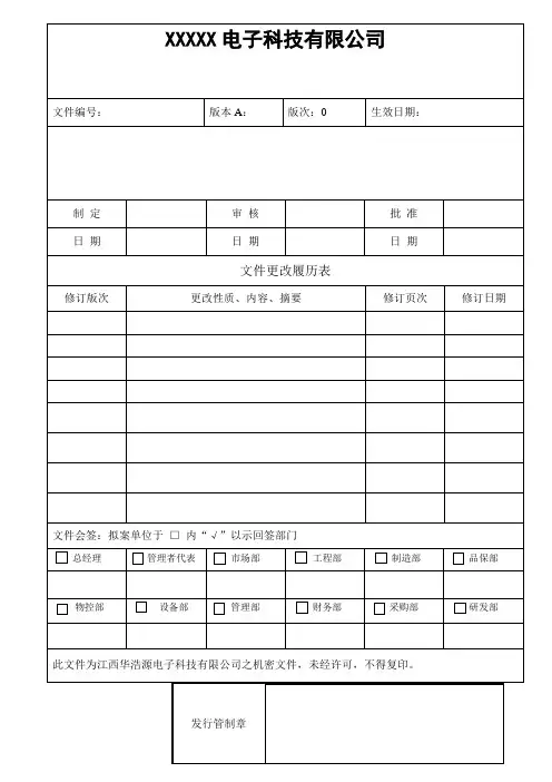
XXXXX电子科技有限公司文件编号:版本A:版次:0 生效日期:制定审核批准日期日期日期文件更改履历表修订版次更改性质、内容、摘要修订页次修订日期文件会签:拟案单位于□内“√”以示回签部门总经理管理者代表市场部工程部制造部品保部物控部设备部管理部财务部采购部研发部此文件为江西华浩源电子科技有限公司之机密文件,未经许可,不得复印。
发行管制章XXXXX电子科技有限公司快压机操作指引规范制作单位:文件编号:生效日期:版本号:总页数:第1页共3页1.0目的:规范员工操作,提高工作技能。
2.0适用范围:本规范适用于本公司快速层压机的操作。
3.0操作程序3.1打开电源开关进入参数设置:如下图指示第一步:进入第二步:参数设定第三步:温度设定3.2层压机自动程序:合模→预压压力→预压计时→升压至成型压力→热压计时→全压(补压/泄压)→热压时间到→自动开模3.3工作液压力低压:10kg/c㎡高压:140 kg/c㎡3.4工作台面规格450mm×382mm3.5最高工作温度:≤200℃快压机操作指引规范生效日期:版本号:总页数:第2页共3页4.0操作内容4.1开机先检查设备是否正常,液压缸油位是否处于使用状态下。
4.2 生产前必须要先做首板检查,包括外观和性能检测(浸焊性、剥离强度、整体的厚度)等。
4.3在生产过程中如果出现参数异常立即按急停,不必关闭电源、以便于上下模自动恒温。
4.4 FPC板压制检OK后必须烘烤,烘烤温度:160℃,时间:1小时;除非有特殊规定以外的不用烘烤。
4.5生产完毕后先将热盘合模然后在关闭电源以便于保持热盘的清洁度。
4.6使用单面离型膜时,离型油面必须贴于板面。
(用美纹胶粘离型膜两面、不粘的一面为离型油面)各类辅料型号分类摆放,以免混乱。
4.7在压合过程中必须每批板做首检,首检交由品质部确认OK后方可进行批量生产,中途每张板必须目视自检一次。
4.8机器设定最大压力不可超过140 kg/C㎡,设定最高温不可超过200℃,压合板总厚度(包括补强)不能超过0.4mm5.0各材料清洁及更换频率5.1每班生产前必须对热盘、硅胶垫、工作台面等全部清洁一遍。
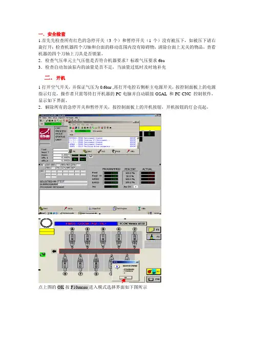
一.安全检查1.首先先检查所有红色的急停开关(3个)和暂停开关(1个)没有被压下,如被压下请右旋打开;检查机器四个刀轴和台面的移动范围内没有障碍物,清除台面上无关的物品,查看机器的四个刀轴上刀具是否锁紧,2.检查气压单元主气压值是否符合机器要求?标准气压要求6ba3.检查自动加油泵内的油量是否不足,当油量过低时及时地补充二.开机1打开空气开关,并保证气压为0.6bar ,再打开电控右侧柜主电源开关,按控制面板上的电源指示灯亮,操作者只需等待打开机器的PC电脑并自动联接OSAL 和FC-CNC 控制软件,显示如下界面,2.解除所有的急停开关和暂停开关,按控制面板上的开机按钮,开机按钮的灯会亮起,点上图的OK 按F10menu进入模式选择界面如下图所示鼠标点击上图右上角的F2显示加式参数列表,鼠标点击上图右上角的F3显示台面上压料夹摆放坐标列表,鼠标点击上图右下角的F7显示加工程式时刀具参数,包括各个刀具的转向直径补偿量转速鼠标点击上图右下角的F10menu进入模式选择界面如下图所示左边的F1~F9以次代表F1Heads 刀具参数,刀具的直径转速旋转方向,F2 Clamp /posit 压料夹坐标列表压料夹坐标位置F4 Feed 加工速度可以编辑加工速度F5 Mamual 进入手动模式F6Testing cycle 测试模式,可对多个或单个刀轴进行加工测试检查,F7Program 程式管理模式F8disconect 联接状态在图标为绿色的情况下表示PC 和NC为联接状态F9 exit 退出FCCN控制界面三.激活小键盘和打开安全门开机后鼠标点击上图右侧的F4opendoor打开安全门为绿色时表示激活鼠标点击上图右侧的F5keypad激活小键盘,为绿色时表示激活(正常状态下开机后KEYPAD和KEYPADENABLESPINDLE都要求是高亮黄颜色激活状态如下图所示)四.机器开机回原点将台面上方的压料气缸压下,再将小键盘上的速率旋钮打到最小,按控制面板上的回原点按钮或者按上图右边的F2autohome,然后通过旋转小键盘上的速率旋钮将各轴的移动速度渐渐加快,左右四个刀轴会自动远离台面移动到机器设定的原点后,台面X轴才会自动移动退回到原点位置,在机器移动前确认机器的移动范围内没有人员和物料以免造成碰撞五.手动模式按F6JOG 为绿色时,如下图所示此时将小键盘上的速率旋钮打到最小,按小键盘上的+X,小键盘上的速率旋钮调大,X轴会移动台面,如按电脑上的1或3或4,再按小键盘上的+Y,1号刀头2号刀头3号刀头4号刀头会分别向台面方向移动,按-Y各刀轴会分别向远离台面方向移动五.程式调入与激活先在专用的编程软件里将刀具路径编写好,然后产生NC代码,才可以把NC代码调用。
Table of contents1. PREVENT UNAUTHORIZED OPERATION. Do not permit anyone to operate this equipment unless they have read and thoroughly understood this manual.2. WEAR SAFETY GLASSES.3. AVOID PINCH POINTS. Do not rest your hand on the crimp ring. Keep your hands clear of all moving parts. Do not allow anyone, other than the operator, close to the equipment while it is in operation.4. MAINTAIN DIES WITH CARE. Dies used in the T-420 crimp machine are hardened steel, offering the best combination of strength and wear resistance for long life. Hardened dies aregenerally brittle and careshould be taken to avoidany sharp impact. Neverstrike a die with a hardenedinstrument.5. USE ONLY SPECIFIEDDANFOSS PRODUCTS.Make hose assemblies usingonly Danfoss's hose andDanfoss fittings specified forthis assembly equipment.6. VERIFY CORRECT CRIMPDIAMETERS. Check andverify correct crimpdiameters of all fittings aftercrimping. Do not put anyhose assemblies into serviceif the crimp diameters donot meet Danfoss crimpspecifications.7. MAKE SURE ALL DIES ARECOMPLETELY IN PLACE,the spacer ring rests againstthe locator bracket, and thepusher halves are closedbefore crimping.8. DO NOT OVER PRESSURIZE.Do not exceed the 5,000 psihydraulic pressure suppliedto the machine9. DIE CHANGE. DO NOTINSERT/REMOVE DIESWHILE THE POWER ISON OR MACHINE IS INOPERATION.10. SECURE THE EQUIPMENTTO A STABLE WORKSURFACE. Prior tooperation, secure thecrimp machine to a stablework surface to preventthe equipment fromtipping. See pages 4-5 formounting instructions.11. UNPLUG THE POWERSUPPLY WHEN NOT INUSE.12. KEEP WORK AREA CLEAN.Cluttered areas andbenches invite accidents.13. DO NOT OPERATEWITHOUT THE BASEADAPTER RING IN PLACE.Safety instructionsT-420 Crimp machineDanfoss's hose and Danfoss hose fittings should only be assembled using Danfoss approved assembly equipment. Do not use any combinationsof Danfoss's hose, Danfoss hose fittings, or Danfoss assembly equipment with hose, hose fittings, or assembly equipment supplied by another manufacturer.Danfoss hereby disclaims any obligation or liability (including incidental and consequential damages) arising from breach of contract, warranty, or tort (under negligence or strict liability theories) should Danfoss hose, Danfoss hose fittings, or Danfoss assembly equipment be used withany hose, hose fittings, or assembly equipment supplied by another manufacturer, or in the event that product instructions for each specified hose assembly are not followed. (Reference SAE J1273 – Recommendedpractice for hydraulic hose assemblies).Failure to follow Danfoss processes and product instructions and limitations could lead to premature hose assembly failures, resulting in property damage, serious injury, or death.Danfoss fitting tolerances are engineering to match Danfoss's hose tolerances. The combination or use of Danfoss's hose and hose fittings supplier by another manufacturer may result in the production of unreliable and/or unsafe hose assemblies and is neither recommended nor authorized by Danfoss.Read and understand the operator’s manual before attempting to operate any equipment.Section PageSafety instructions 2Specifications and equipment 3T-420 Crimp machine 3Power source options 3Mounting instructions 4 - 5Check-out procedure 6Operating instructions 7-8Adapter rings 8Spacer ring and nominal crimp diameter measurement 8Troubleshooting procedures 9-10Repair and replacement items 112Danfoss T-420 Crimp machine operator´s manual December 20223Danfoss T-420 Crimp machine operator´s manual December 2022CAUTION: The above pumps have the pressure relief valveset at 4,000 - 4,200 PSI, Damage to the press may result and warranty may be voided if higher pressures are used.Specifications and equipment T-420 Crimp machine and accessoriesT-420 Crimp machineThe T-420 is a versatile machine ideal for your shop, factory, construction, and mine locations. Large capacity combined with lever-activated crimping givesyou wide coverage and a quick and simple way to make factory-quality hose assemblies. The T-420 press offers crimping capabilities through 1-1/4”. I.D. four spiral hose.Weight 210 lbs.Size 22”high, 20-1/2”deep, 10”wide T-421U Electric pump (220 volt) T-421UCSA CSA approved Dimensions 7½” high, 10” wide, 22” long Weight 75 lbs.Pressure 4000-4200 psi Reservoir capacity 6 Quarts Outlet port size ¾-16 Straight thread Motor 1HP , 3450 RPM, 220 volts, 60 cycle, Single Phase Hydraulic oil ISO 32 (SAE 10W)Flow 2.5 GPM to 750 psi. 0.5 GPM above 4000 psi *For low temperature applications automatic transmission fluid can be substituted.Note: It is recommended that the electric pump be used on a 15 amp. fused circuit. Pump wired for 220 volts, single phase.T-421U-110 Electric pump (110 volt) For dimensional data other than voltage information, refer to T-421U see above.T-421U-110CSA CSA approved Note: It is recommended that the electric pump be used on an individual 30 amp. fused circuit. Pump wired for 100 volts, single phase Pump kit part numbers ET420-007 110 volt electric pump kit with hose assembly ET420-007CSA 110 volt electric pump kit with hose assembly, CSA approved ET420-008 220 volt electric pump kit with hose assembly ET420-008CSA 220 volt electric pump kit with hose assembly, CSA approvedCrimp machine part numbersT-420-1 Base T-420 machineT-420-1CSA Base T-420 machine, CSA approvedCrimp machine and tooling package part numbersT-420-001 Contains T-420 crimper, 220v pump kit,T420TP-1001 tooling packageT-420-002 Contains T-420 crimper, 110v pump kit,T420TP-1001 tooling packageT-420-001CSA Contains T-420 crimper, 220v pump kit,T420TP-1001 tooling package, CSA approvedT-420-002CSA Contains T-420 crimper, 110v pump kit,T420TP-1001 tooling package, CSA approvedCrimp machine and tooling package part numbersT420TP-1001 New placement tooling packageCapabilities: Braided -4 thru -20, Spiral -8 thru -20T420TP-1002 Winner tooling packageCapabilities: Braided -4 thru -20, Spiral -6 thru -20*both packages exclude -5 and -10 sizes4Danfoss T-420 Crimp machine operator´s manual December 2022Mounting InstructionsC-40X CabinetThe C-40X Stock Cabinet is designed specifically for the T-420-1press and T-421U electric pump. Holes are pre-drilled so that thepress and pump can be mounted conveniently on top of thecabinet. The C-40X cabinet has 40 heavy duty plastic drawerswhich divide into two, three or four compartments providingample space for a large selection of hose ends and adapters.CAUTION: It is recommended these instructions be read thoroughly prior to set-up, and then used as a guide during actual assembly.STEP 1: Remove packaging from C-40X cabinet.STEP 2: Remove shipping carton from T-420-1 press. There aretwo 1/2”-13 tapped holes in top of plate which may be used forlifting purposes (figure 1 ).STEP 3: Using an adequate lifting device, raise the press to theleft side of cabinet. Align holes in press support brackets withpredrilled holes in cabinet. Insert bolts (found in cabinet) throughtop of cabinet. Washers and nuts are installed from underneath.Tighten.STEP 4: The T-421U Electric Pump mounts on the right side ofthe cabinet. Predrilled holes align the pump. Insert bolts throughtop of cabinet. Washers and nuts are installed from underneath.Tighten.STEP 5: Remove plug from outlet port in pump.STEP 6: Locate press/pump connecting hose assembly (T-410-22) and remove 4315X8 For-Seal adapter. Thread adapter intooutlet port in pump (step 5).STEP 7: Connect Hose assembly (T-410-22) to For-Seal adapteron press and pump. Tighten.STEP 8: Before the electric pump (T-421U) can be activated,the male and female electrical disconnects must be mated. Thefemale half and wire harness is shipped with the T-421U pump.Both male and female halves are keyed so that they can be con-nected in only the correct position. After the connection is made,tighten the knurled nut.STEP 9: Plug electric cord into a grounded 220 volt, 60 cycle,single phase outlet. THE PUMP MUST BE ON A 15 AMP FUSEDELECTRICAL CIRCUIT. If using T-421U-110 110v pump, plug elec-tric cord into a grounded 110 volt, 60 cycle, single phase outlet.The pump must be on a 30 amp fused electrical circuit.FF91420 CartHoles are pre-drilled for the T-420 and ET4001 crimp machines.FF91420 Cart½ -13UNC-2Bx ¾DP . TAPPED HOLES(2 PLACES)Figure 1 - Lifting hole Layout on Top PlateMounting Instructions Bench/Work TableThe following method of mounting your T-420 equipment package is offered as a guide and may be varied to suit your particular needs.1. Prepare mounting surface for T-420 press and pump.IMPORTANT: Care should be taken to ensure themounting surface is capable of supporting the weight of the press (210 lbs.) and power source (75 lbs.)2. Remove shipping carton from T-420-1 press. There aretwo 1/2-13 tapped holes in top of plate which may be used for lifting purposes (see Figure 1, Page 4).3. Using an adequate lifting device, raise the press tothe mounting surface. Align holes in press supportbrackets with holes in mounting surface. Insert boltsthrough top of mounting surface. Washers and nuts are installed from underneath. Tighten.4. Place the T-421U power unit on mounting surface tothe right and slightly behind the T-420-1 press5. Mark mounting hole location for power unit and drillholes in mounting surface.6. Replace power unit and align holes on mountingsurface with base plate on power unit. Insert boltsthrough top of mounting surface. Washers and nutsare installed from underneath. Tighten.7. Remove plug from outlet port in pump.8. Locate the T-421U power unit on mounting surface tothe right and slightly behind the T-420-1 press.9. Connect Hose assembly (T-410-22) to 4315X8 For-Sealadapter on press and pump. Tighten.10. Before the electric pump (T-421U) can be activated,the male and female electrical disconnects mustbe mated.11. Plug electric cord into a grounded, 220 volt, 60 cycle,single phase outlet. THE PUMP MUST BE ONAN INDIVIDUAL 15 AMP FUSED ELECTRICALCIRCUIT.If using T-421U-110 pump, plug electric cord inot a grounded 110 volt, 60 cycle, single phase outlet. The pump must be ona 30 amp fused electrical circuit.Figure 2 -Typical T-420 Equipment Set Up on Shop/Work Table5Danfoss T-420 Crimp machine operator´s manual December 2022Check out proceduresCAUTION: Throughout the Check-out Procedure check hoseassembly/adapter connections for any leaks. TIGHTEN if necessary.CHECK oil level in power unit. The oil reservoir was filled at the factory; however, if oil is required use ISO 32 (SAE 10W) hydraulic oil or equivalent.1. Remove pipe plug from fluid fill port on top ofreservoir and replace with plastic breather cap.2. Plug power cord into 220 volt, 60 cycle, single phaseoutlet. It is recommended that the pump be on anindividual 15 amp fused electrical circuit. If usingT-421U-110 pump, plug power cord into 110 volt,60 cycle, single phase outlet. It is recommended thatthe pump be on an individual 30 amp fused electrical circuit.3. Pull activating lever down. Pusher halves will close.Continue to pull activating lever down until pump is activated. Hold down until pump bypasses.4. Release activating lever. Pump will stop and pusherwill retract.5. Repeat Steps 3 and 4 approximately six times.This will purge the hydraulic system.Check-out using electric pump(T-421U or T-421U-110)6Danfoss T-420 Crimp machine operator´s manual December 20227Danfoss T-420 Crimp machine operator´s manual December 2022Operating instructions1. Measure the appropriate insertion depth and scribe aT-marking on the hose. Insert the hose into the fitting.The socket should cover a portion of the depth markingor be fully bottomed out into the fitting.3. Insert hose assembly from bottom between collethalves. Our optimized tooling provides built in fittinglocators, ensuring correct alignment for optimal crimpposition. 5. Release activating lever. Pusher will automatically retract and pusher halves will open. Remove factory quality crimped hose assembly and visually inspect.6. To ensure a proper crimp has been completed, measurethe nominal crimp diameter as shown in figure on page 82. To establish the crimp settings and tooling needed,access the PowerSource Crimp Spec Tool from the ToolsMenu on PowerSource.Select proper size collet for hose type and size beingcrimped. Apply grease to outside of each collet segment.Insert collet in cavity of base plate. Place spacer ring ontop of collet if called for in the crimp spec.4. Pull activating lever down. Pusher halves will close.Continue to pull activating lever down (pump will activate)until pusher contacts the base plate. The crimp is complete.8Danfoss T-420 Crimp machine operator´s manual December 20228Operating instructions Spacer ring and nominal crimp diameter measurementSpacer ringTypical spacer ring illustratingboth sides of ringNominal crimp diameter measurementMeasuring crimp diameters should be a part of the normal hose assembly procedure. To ensure a proper crimp diameter reading, follow these steps:1. Measure the diameter in the middle of the crimped portion of the hose end.2. Place the caliper in a position to allow for a measurement across the pressed (flat) portion of the crimp.3. See crimp diameters in crimp specifications.MaintenanceCollet assembly lubrication Every 30 crimps = Re-lubricate sliding surfaces of dies Every 250 crimps = R emove old grease and re-lubricate Base adapter ring lubrication Every 250 crimps = Remove old grease and re-lubricate Every 1,000 crimps = R emove old grease, inspect forwear or damage and re-lubricate if okay.Flat sideCounterbore side9Danfoss T-420 Crimp machine operator´s manual December 20229Troubleshooting proceduresT-421U and T-421U-110 Electric pumpTroubleshooting T-421U and T-421U-110 electric pump IMPORTANT: Pressure must be relieved from system before disconnecting hose, installing gauge or removing valves from pump.Check fuse, loose wire connections, switch malfunctions or damaged cord. Pump electric cord must be plugged into a grounded 220 volt, 60 cycle, single phase outlet on a 15 amp fused electrical circuit. If using T-421U-110, pump electric cord must be plugged into a grounded 110 volt, 60 cycle, single phase outlet on a 30 amp fused electrical circuit.Check oil level - after assembly and system has been purged of air the fluid level should be 1/2”from top of reservoir. Clean, anti-wear type, hydraulic oil having a (ISO 32) 300 SSU/100 F is recommended. Use only if operating temperature is above 0°F or below 160°F. Oil is needed to: 1) Transmit power easily through system 2) Lubricate moving parts 3) Provide seal clearances between parts 4) To cool or dissipate heat Clean or Reset Relief Valve - A 6000 PSI pressure gauge, a 5/16” Allen wrench, a 1” socket and a screwdriver are required. Remove cap from relief valve. Remove adjustment screw, spring and ball. Ball should be attached to spring. Check ball and seat for possible scoring. Replace spring and ball in cavity. Insert a small punch through spring against ball. Give punch a moderate tap to seat ball. Return adjustment screw to original position making sure adjustment screw is at least one turn from bottoming. Remove 3/8” NPTF plug from port above check valve and install 6000 PSI pressure gauge. With 6000 PSI pressure gauge in place operate unit to full crimping position. Gauge should read 4000-4200 PSI. To raise setting, turn screw in (clockwise); to lower turn screw out (counterclockwise) in 1/4 turn increments. After each adjustment recycle and read gauge for proper setting. Run a cycle of the crimping system for final gauge reading before removing gauge and reinstalling pipe plug. Shuttle Valve - If the shuttle valve is in a closed position and pusher will not retract it may be helpful to tap the shuttle valve cap several times to dislodge any silt that may be causing stem to bind. If this does not free valve and allow pusher to retract use extreme caution prior to proceeding with shuttle valve removal as the system is still under pressure. It may be advisable to relieve pressure at a hose connection to avoid an oil bath. After pressure is removed from system, remove cap and valve cartridge. Soak cartridge in a PETROLEUM BASED SOLVENT ONLY (clean Stoddard solvent). Do not use Triethene, Gasoline or Paint Thinner as they will damage the 0-Ring Seals. If cartridge disassembly is required, use care in removing stem as it has a .0005 metal seal fit. Rotate stem in solvent and push from seat end to remove from cartridge. Do not lose the loose ball. Wash parts in clean solvent and examine for any surface markings. If necessary, polish with a fine crocus cloth. After final cleaning reassemble cartridge. Shake cartridge and check for free movement of ball and stem. Replace cartridge if not functional at this point. Reassemble shuttle valve into its cavity and check crimping cycle prior to using system.Step 1:Step 2:Step 3:Step 4:10Danfoss T-420 Crimp machine operator´s manual December 2022Troubleshooting proceduresT-421U and T-421U-110 Electric pumpTroubleshooting T-421U and T-421U-110 Electric Pumps (For steps please refer to page 9)11Danfoss T-420 Crimp machine operator´s manual December 2022T-420 Repair and replacement itemsCatalognumber Description T-420-1M Micro-switch for T-420-1 pressT-420-28 Tool locator bracketT-420-B Pusher bolt and washersW-EQCR-TE006-E Shroud decalT-420-H HandleT-420-L Light bulbT-420-LA Light assemblyT-420-LS Light switchT-420-P Pusher set (2) with wear plates and screwsT-420-S Press shroud with decalsT-420-26 Insert – base plateT-420-G Linkage assemblyT-420-2R RackT-420-2K Pinion shaft assembly(incl’d T-420-2G, T-420-2R and T-420-2S)T-420-2S Replacement pinion gear shaft140-06745 Pusher wear plates includes (1) left and (1) right140-06748 Pusher wear plates screws (1)FF91042 Cart for ET4001 or T-420Assembly EquipmentT-420 Repair and replacement itemsDanfoss can accept no responsibility for possible errors in catalogs, brochures, and other printed material.Danfoss reserves the right to alter its products without notice. This also appliesto products already on orderprovided that such alterations can be made without subsequent changes being necessary in specifications already agreed. All trademarks in this material are property of the respective companies. Danfoss and the Danfoss logotype are trademarks of Danfoss A/S. All rights reserved.AN436777624684en-000101© Danfoss | Danfoss T-420 Crimp machine operator´s manual | Machines, Tools & Accessories | JC | December 2022。
HK043系列一体机简要说明安全注意事项!危险由于没有按要求操作,可能造成死亡或重伤的场合。
1、不要安装在含有爆炸气体或可燃气体的环境里,否则有引发爆炸的危险。
2、必须由具有专业资格的人员进行配线作业,否则有触电的危险。
3、确认输入电源处于完全断开的情况下,才能进行配线作业,否则有触电的危险。
4、通电情况下,不要用手触摸控制端子,否则有触电的危险。
!注意由于没有按要求操作,可能造成中等程度伤害或轻伤,或造成物质损害的场合1、配线安装时,不要将铁屑、电线屑落入一体机内部,否则有火灾及物质损坏的危险。
2、不要安装在阳光直射或雨水溅到的地方,否则有损坏器件的危险。
3、严禁将电源输入端子接上交流220V电源,否则有火灾及器件损坏的危险。
4、通电前,请再次确认配线是否正确,错接可能会导致器件损坏的危险。
使用注意事项●一体机的安装位置尽量远离高电压、强电流、高频率等对周围有较强干扰的设备。
●请一定在一体机外部组成紧急停电电路,制止正反动作同时进行的连锁电路、上下限定位连锁电路。
●一体机指令集有88条指令,如果程序中含有超出这88条指令范围的指令,运行时会出错。
●在通电的状态下,不能带电插拔任何端子及通讯线,否则会导致一体机控制器内部元件损伤。
●在下载梯形图时,下载完毕后,将拨码开关拨到RUN,等一体机控制器运行后,才能断电,否则,程序得不到固化。
●对于变更运行中的程序、强制输出、RUN、STOP等操作,必须熟读使用手册,充分确认其安全之后进行。
1导言HK043系列一体机结构小巧,功能强大,带有2路AB相脉冲计数,2路高速脉冲输出及基本的开关量输入输出功能,模拟量输入、输出,RS485(MODBUS)通讯等功能。
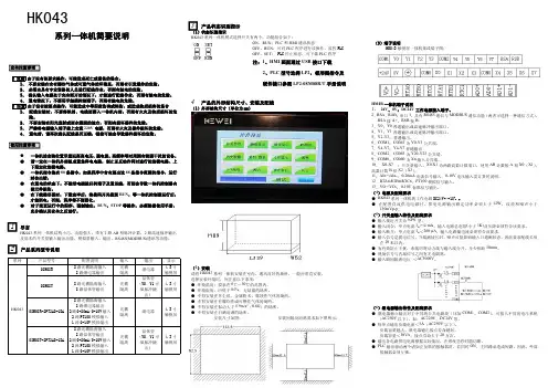
2产品系列型号说明系列产品型号配置说明输入输出显示HK04308M08R8路光耦隔离输入8路继电器输出光耦隔离继电器4.3寸触摸屏08M08T8路光耦隔离输入8路晶体管输出光耦隔离晶体管(Y0、Y1可做脉冲输出)4.3寸触摸屏08M08R-2PT2AD-1DA8路光耦隔离输入8路继电器输出2路0-20mA/0-10V输入2路PT100模拟输入1路0-10V模拟输出光耦隔离继电器4.3寸触摸屏08M08T-2PT2AD-1DA8路光耦隔离输入8路晶体管输出2路0-20mA/0-10V输入2路PT100模拟输入1路0-10V模拟输出光耦隔离晶体管(Y0、Y1可做脉冲输出)4.3寸触摸屏3产品状态识别指示(1)状态识别指示HK043系列一体机模式选择开关有两个,功能组合如下:ON、RUN:PLC和HMI通讯状态OFF、RUN:可对PLC程序进行读操作、监控PLCOFF、SET:PLC停止状态,可下载PLC程序注:1、HMI画面通过USB接口下载2、PLC型号选择LP2,梯形图指令及硬件接口参照LP2-08M08R/T手册说明4产品的外形结构尺寸、安装及配线(1)外形结构尺寸(单位为mm)(2)安装请将HK043系列一体机安装在室内、通风良好的场所。
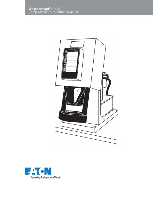
2EATON Weatherhead ET4020 Crimp Machine Operator’s Manual W-EQCR-TM020-E1 August 2010Safety Instructions . . . . . . . . . . . . . . . . . . . . . . . . . . . . . . . . . . . . . . . . . . . . . . . . . . . . . . . . . . . . . . . . . . . . . . . . .3Specifications . . . . . . . . . . . . . . . . . . . . . . . . . . . . . . . . . . . . . . . . . . . . . . . . . . . . . . . . . . . . . . . . . . . . . . . . . . . . .4Accessories . . . . . . . . . . . . . . . . . . . . . . . . . . . . . . . . . . . . . . . . . . . . . . . . . . . . . . . . . . . . . . . . . . . . . . . . . . . . . . .4Setup and Installation . . . . . . . . . . . . . . . . . . . . . . . . . . . . . . . . . . . . . . . . . . . . . . . . . . . . . . . . . . . . . . . . . . . . . .4Operating InstructionsLoading and Unloading Die Cages . . . . . . . . . . . . . . . . . . . . . . . . . . . . . . . . . . . . . . . . . . . . . . . . . . . . . . . .5Operating the Keypad . . . . . . . . . . . . . . . . . . . . . . . . . . . . . . . . . . . . . . . . . . . . . . . . . . . . . . . . . . . . . . . . . .5Entering a Number into the Display . . . . . . . . . . . . . . . . . . . . . . . . . . . . . . . . . . . . . . . . . . . . . . . . . . . . . . .6Storing a Number from the Display . . . . . . . . . . . . . . . . . . . . . . . . . . . . . . . . . . . . . . . . . . . . . . . . . . . . . . .6 Recalling a Number from the Display . . . . . . . . . . . . . . . . . . . . . . . . . . . . . . . . . . . . . . . . . . . . . . . . . . . . .6Crimping Procedures . . . . . . . . . . . . . . . . . . . . . . . . . . . . . . . . . . . . . . . . . . . . . . . . . . . . . . . . . . . . . . . . . . . . . . .7Calibration . . . . . . . . . . . . . . . . . . . . . . . . . . . . . . . . . . . . . . . . . . . . . . . . . . . . . . . . . . . . . . . . . . . . . . . . . . . . . . .8MaintenanceMaintenance Intervals . . . . . . . . . . . . . . . . . . . . . . . . . . . . . . . . . . . . . . . . . . . . . . . . . . . . . . . . . . . . . . . . .9Machine Maintenance Procedures . . . . . . . . . . . . . . . . . . . . . . . . . . . . . . . . . . . . . . . . . . . . . . . . . . . . . . . .9 Die Cage Maintenance Procedures . . . . . . . . . . . . . . . . . . . . . . . . . . . . . . . . . . . . . . . . . . . . . . . . . . . . . . .9Troubleshooting Tips . . . . . . . . . . . . . . . . . . . . . . . . . . . . . . . . . . . . . . . . . . . . . . . . . . . . . . . . . . . . . . . . . . . . . .10Crimp Machine Components . . . . . . . . . . . . . . . . . . . . . . . . . . . . . . . . . . . . . . . . . . . . . . . . . . . . . . . . . . . . . . .11Die Cage Components . . . . . . . . . . . . . . . . . . . . . . . . . . . . . . . . . . . . . . . . . . . . . . . . . . . . . . . . . . . . . . . . . . . . .12Electrical Schematics . . . . . . . . . . . . . . . . . . . . . . . . . . . . . . . . . . . . . . . . . . . . . . . . . . . . . . . . . . . . . . . . . . 13-14Hydraulic Schematic . . . . . . . . . . . . . . . . . . . . . . . . . . . . . . . . . . . . . . . . . . . . . . . . . . . . . . . . . . . . . . . . . . . . . .15Table of ContentsSafety Instructions WARNING1. P revent Unauthorized operation. Do not permit anyoneto operate this equipment unless they have read andthoroughly understand this manual.2. Wear safety glasses.3. A void pinch points. Do not rest your hand on the crimpring. Keep your hands clear of all moving parts. Do not allow anyone, other than the operator, close to theequipment while it is in operation.4. M aintain dies with care. Dies used in the ET4020crimp machine are hardened steel, offering the bestcombination of strength and wear resistance for longlife. Hardened dies are generally brittle and care should be taken to avoid any sharp impact. Never strike a die with a hardened instrument.5. U se only specified Weatherhead products. Make hoseassemblies using only Weatherhead hose and fittingsspecified for this assembly equipment.6. V erify correct crimp diameters. Check and verify correctcrimp diameters of all fittings after crimping. Do not put any hose assemblies into service if the crimp diameters do not meet Weatherhead crimp specifications.7. M ake sure all dies are completely in place and the cageis positioned properly on the pressure plate.8. D o not over pressurize. Do not exceed the 10,000psi hydraulic pressure supplied to the machine. Thissetting is preset at the factory and should not requireadjustment.Note: All components used to connect the pump andcrimp cylinder must meet the criteria set forth in theMaterial Handling Institute Specification #IJ100 forhydraulic jacking applications.9. D ie change. Do not insert/remove dies while the poweris on.10. S ecure the equipment to a stable work surface. Prior tooperation, secure the crimp machine to a stable worksurface to prevent the equipment from tipping.11. U nplug the power supply when not in use.12. K eep work area clean. Cluttered areas and benchesinvite accidents.Failure to follow Eaton process and product instructions and limitations could lead to premature hose assembly failures, resulting in property damage, serious injury or death. Weatherhead® fitting tolerances are engineered to match Weatherhead hose tolerances. The use of Weatherhead fittings on hose supplied by other manufacturers and/orthe use of Weatherhead hose fittings supplied by other manufacturers, may result in the production of unreliable and unsafe hose assemblies and is neither recommended nor authorized by Eaton.Read and understand the operator’s manual before attempting to operate any equipment.Eaton hereby disclaims any obligation or liability (including incidental and consequential damages) arising from breach of contract, warranty, or tort (under negligence or strict liability theories) should Weatherhead hose, fittings or assembly equipment be used with the hose, fittings or assembly equipment supplied by another manufacturer, or in the event that product instructions for each specified hose assembly are not followed.Safety Instructions3EATON Weatherhead ET4020 Crimp Machine Operator’s Manual W-EQCR-TM020-E1 August 2010SpecificationsElectrical RequirementsET4020-115 115-Volt AC single phase (50/60) HzCircuit with a minimum of 25 ampsET4020-230 208 to 230-Volt AC single phase (50/60) HzCircuit with a minimum of 15 ampsCrimp Machine DimensionsWidth 14.25 inchesDepth 25.75 inchesHeight 28.50 inchesWeight 238 poundsProduction CapacityWeatherhead braided and spiral hydraulic hoses which use Z or 430U series hose ends through -20 sizeDie Cage Conversion KitThe following contains components necessary to convert one die cage from the FT1330 configuration to the ET4020 configuration.Part number ..........................................................FT1380-2-3 Die Holder KitA set includes four plates and mounting hardware that can hold up to eight die cages. This kit attaches to the sides of the Weatherhead ET4020 crimp machine.Part number ..........................................................FT1380-2-4Die CagesPart number ...............................................FT1380-275-M070 ...................................................................FT1380-275-M090 ...................................................................FT1380-275-M120 ...................................................................FT1380-200-M150 ...................................................................FT1380-200-M180 ...................................................................FT1380-200-M210 ...................................................................FT1380-200-M240 ...................................................................FT1380-200-M280 ...................................................................FT1380-200-M320 ...................................................................FT1380-200-M370 ...................................................................FT1380-200-M420 ...................................................................FT1381-200-M465 1. M ount your Weatherhead ET4020 crimp machine onto a workbench that will support at least 300 pounds. Secure the unit using the holes provided in the corners of the crimp machine base.2. R emove the plug from the hydraulic reservoir vent port and replace it with the vent cap that is supplied with the unit.3. C AUTION: Failure to do so will cause cavitation and damage to the pumping mechanism. Hand tighten the vent cap.CAUTION: Provide electrical service with a dedicated ciruit (per the crimp machine electrical requirements) to eliminate the possibility of a low-voltage situation.4. N ever use an extension cord, always plug directly into the power outlet.SpecificationsAccessoriesSetup and Installation4EATON Weatherhead ET4020 Crimp Machine Operator’s Manual W-EQCR-TM020-E1 August 2010Operating InstructionsTo load the die cage, press and hold the RETRACT switch (figure 1) until the crimp ring reaches the “full retract” position and stops. The die cage may be inserted or removed in this position (figure 2). The ET4020 crimp machine will automatically retract when it has reached the setting entered on the keypad (this is when crimp is complete).1. T he DISPLAY shows the three-digit setting that will determine the crimp diamater. The ratio of the crimp diameter change to the DISPLAY change is 1 to 1. For example, if you crimp a fitting at a setting of 120, and the crimp diameter is .035 inch too large, you will need to decrease the DISPLAY by .035 to (120-035) = 085. A display of 085 should produce the correct crimp diameter.2. T he STORE button is used to store the DISPLAY reading in any of the 10 numbered keys. The green light next to the STORE button will illuminate when you are working in the STORE mode.Loading and Unloading Die CagesFigure 1Figure 2Operating the Keypad“Full retract” position5 EATON Weatherhead ET4020 Crimp Machine Operator’s Manual W-EQCR-TM020-E1 August 2010Operating Instructions3. T he ENTER button is used to put any three-digit number into the DISPLAY. The green light next to the ENTER button will illuminate when you are working in the ENTER mode.4. T he numbered keys have two functions:a. I n the Enter mode, their numeric value is put into theDISPLAY.b. In the STORE mode, they act as 10 different locationsin which to store a DISPLAY setting.Entering a Number into the Display1. T urn the power control switch on the back of the crimp machine to the ON position. The work light and the DISPLAY will illuminate to show that the power is on.2. P ress the ENTER button (the green light next to the ENTER button will illuminate).3. P ress three numerical buttons in less than five seconds. (If more than five seconds elapse, the display reverts back to its previous setting.) After the third number is entered, the display will remain.4. T he ET4020 is now ready to crimp to the DISPLAY setting.Storing a Number from the Display as a Preset1. E nter a three-digit number as described in the procedure above.2. P ress the STORE button. (The green light next to the STORE button will illuminate.)3. P ress and hold down any one of the ten numerical buttons for three seconds. (At the end of three seconds, the green light next to button will illuminate, indicating that the display has been stored to that button.)Recalling a Preset into the Display1. M ake sure that the STORE and ENTER lights are off. (If one is on, it will go off in five seconds if left untouched.)2. P ress the button that has the stored setting for a given hose and fitting style. This setting will then be seen in the DISPLAY.Operating the Keypad (cont.)6EATON Weatherhead ET4020 Crimp Machine Operator’s Manual W-EQCR-TM020-E1 August 20107EATON Weatherhead ET4020 Crimp Machine Operator’s Manual W-EQCR-TM020-E1 August 2010Crimping ProceduresRefer to the current Weatherhead Crimp Specifications bulletin for complete and detailed crimp specification information for each hose and fitting style.1. R etract the crimp ring by depressing the retract switch until the crimp ring is fully retracted. Select the proper die cage from the current Weatherhead Crimp Specifications bulletin. Slide the die cage into the cage holder slots.2. P ress the proper PRESET button or key in a value to the DISPLAY (see example).3. P osition the fitting within the crimp cage according to the corresponding figure in the current Weatherhead Crimp Specifications bulletin. (Z Series fitting is shown in Figure 3).4. T o crimp the fitting, depress the CRIMP switch. The crimp ring will rise until the fitting is fully crimped (Figure 4). It will then stop and begin to retract, signifying that the crimp is complete. Remove your finger from the CRIMP switch. The crimp ring will automatically retract.Hint: Retraction can be halted at any point by momentarily depressing the RETRACT switch, and then resumed by depressing and holding the RETRACT switch.5. V erify correct crimp diameter.Reminder:Full retraction is required for changing die cages.WARNING: Maintain clear distancefrom all moving parts.Figure 3Figure 4Example: Enter the number “300” into the DISPLAY and start the crimping process. If the dies crimp the fitting, measure the crimp diameter and decrease the DISPLAY setting by the same amount that you wish to decrease the crimp diameter. If the dies don’t touch the fitting, lower the DISPLAY setting by 050 to “250” and try to crimp the fitting again. If that still isn’t enough, continue to reduce the DISPLAY setting by 050 increments until the dies make contact with the fitting. Then measure the crimp diameter and decrease the DISPLAY setting by the same amount that you wish to decrease the crimp diameter.If a display setting of “250”, using H28008 hose with Z Series fittings produces a crimp diameter of 1.124 inches, subtract the crimp specification (0.990 inches) from the diameter that you need measured (1.124-0.990=0.134). Then, subtract “134” from the DISPLAY setting (250-134=116) and change the DISPLAY to “116”. Crimp the fitting again and measure the crimp diameter. If the crimp diameter is still too large, repeat this process.Proper Crimping Position for Z Series Fittings8EATON Weatherhead ET4020 Crimp Machine Operator’s Manual W-EQCR-TM020-E1 August 2010CalibrationMust do Part I and Part IIWARNING: Maintain clear distancefrom all moving parts.The calibration procedure below will calibrate the Weatherhead ET4020 crimp machine to the original factory setting. While new machines are calibrated at the factory and will be ready to use out of the crate, this procedure should be followed if the crimp machine has been disassembled or has had components replaced. The procedure requires the use of an FT1380-200-M240 die cage, a Z Series -8 fitting and a Z Series -12 fitting.Caution: While in the calibration mode, follow the instructions precisely and press the keys deliberately. If a mistake is made, the calibration procedure must be started over from the beginning.Part I1. I nsert an FT1380-200-M240 die cage.2. P ress the STORE and ENTER buttons simutaneously, then release. Both button lights will now be illuminated and will remain so until the calibration procedure is finished.3. E nter in the value of “100” using the keypad. (Don’t hit enter.)4. C enter a Z Series -8 fitting (without a hose) in the die cage, holding the socket or fitting in place with a pencil or other suitable tool. Crimp the socket by depressing the crimp switch until the machine retracts by itself, indicating a completed cycle. Allow the crimp ring to return to the “soft retract” position.5. U sing a set of calipers, measure the crimp diameter. The preferred method is to use the average of the four pairs of indentations.6. L ocate the crimp diameter in Table A, below. Using the keypad, enter in the three-digit Display Reading that corresponds to the Crimp Diameter.Note: If your Crimp Diameter falls between the numbers shown in Table A, simply determine or interpolate the Display Reading, since the numbers are a direct ratio.Part II1. E nter in the value of “400” using the keypad. (Don’t hit enter.)2. C enter a Z Series -12 fitting (without a hose) in the die cage, holding the socket or fitting in place with a pencil or other suitable tool. Crimp the socket by depressing the crimp switch until the machine retracts by itself, indicating a comleted cycle.3. R epeat steps 5 and 6 at left, except use Table B instead of Table A for the -12 fitting.4. A fter the three-digit Display Reading is entered, the machine will automatically exit the calibration mode.Calibration Example Part I Crimp a Z Series -8 fitting and measure the four crimp diameters around the socket. For example, the diameters measure .942, .946, .945 and .945 inches, to obtain the average diameter, add the four diameters and divide that sum total by 4. (.942+.946+.945+.945) = 3.778 = 0.9445 = 0.945 4 4 (round to nearest thousandth)Look at the Crimp Diameter column in Table A and find your average diameter. If it falls between two numbers, as this one does, interpolate the desired setting. In this case, you would enter 045. If your crimp diameter was .940, you would enter 040; if it was .942, you would enter 042.Part II Crimp a Z Series -12 fitting and measure the four crimp diameters around the socket. This time, let’s say that the diameters measure 1.247, 1.249, 1.249 and 1.248 inches. Average the measures by adding the four diameters and dividing that sum total by 4.(1.247+1.249+1.249+1.248) = 4.993 = 1.24825 = 1.2484 4(round to nearest thousandth)Look at the Crimp Diameter column in Table B and find your average diameter. If it falls between two numbers, as this one does, interpolate the desired setting. In this case, you would enter 348. If your crimp diameter was 1.250, you would enter 350; if it was 1.249, you would enter 349.Table A for -8Crimp Display Diameter Reading 0.940 0400.950 0500.960 0600.970 0700.980 0800.990 0901.000 1001.010 110Table B for -12Crimp Display Diameter Reading 1.240 3401.250 3501.260 3601.270 3701.280 3801.290 3901.300 4001.310 410Maintenance IntervalsDie Cage Lubrication Crimp Ring Maintenance Maintenance ProceduresEvery 50 crimps Relube sliding surfaces of dies Every 500 crimps Remove old grease and relube Every 1000 crimps Die cage maintenanceEvery 500 crimps Remove old grease and relube Every 2000 crimps Remove old grease, inspect forwear or damage and relube if okay Use NEVER•SEEZ lubricant (Weatherhead part numberFT1092)Machine Maintenance Procedures1. S liding surfaces must be kept free of dirt and other abrasive materials.2. A ll exposed black metal surfaces should be coated occasionally with a light film of oil to prevent corrosion.3. P eriodically check the oil level in the fluid reservoir of the hydraulic power unit. Maintain the oil level according to the indicator on top of the reservoir. Add ENERPAC hydraulic oil as needed.Note: Completely retract the crimp ring when checking the oil level.Die Cage Maintenance Procedures1. L ubricate the die cage. For maximum service, ET4020die cages require lubrication at 50-crimp intervals withNEVER•SEEZ (Weatherhead Part Number FT1092).FT1092 is an eight ounce container that will providesufficient lubricant for about 5,000 crimps.Periodically remove NEVER•SEEZ residue that has builtup on the sides of the dies and in the crimp ring duringthe crimping process. NEVER•SEEZ residue becomescontaminated with metal and plating chips and airbornecontaminants, which can cause premature wear of thedies and crimp ring. It should carefully be removed withoutmixing it with newly applied NEVER•SEEZ.2. D ie cage maintenance should be performed at 1000-crimp intervals or every six months, which ever occursfirst. Die cages should be free of grease and debris andinspected for worn or damaged components.a. T he sliding surface of the dies should appear smoothwith no apparent galling. Galled dies must bereplaced. Individual dies in a cage can be replacedwithout replacing all eight dies.b. R eplace springs that show any sign of damage orcollapse such as those which are shorter than theother springs.c. T he spring plate should appear smooth with noapparent galling. Galled spring plates must bereplaced.d. I nspect remaining components, and replace thosethat are badly worn.Reassemble components, and liberally apply NEVER•SEEZto the die surface which slides along the spring plate.Torque the die cage bolts to 50 in. -lbs.Ensure that all dies slide in and out freely.9EATON Weatherhead ET4020 Crimp Machine Operator’s Manual W-EQCR-TM020-E1 August 201010EATON Weatherhead ET4020 Crimp Machine Operator’s Manual W-EQCR-TM020-E1 August 2010Crimp Machine ComponentsEATON Weatherhead ET4020 Crimp Machine Operator’s Manual W-EQCR-TM020-E1 August 2010Die Cage ComponentsFT1380-2-9 FT1380-2-9A FT1381-2-9Detail Number Bill of Material Bill of Material Bill of Material Description Qty Req’d1 FT1330-2-9-21 FT1330-2-9-2 FT1330-2-9-21 Die Spring 8 or 16*2 FT1380-2-9-3 FT1380-2-9-2 FT1381-2-9-3 Front Plate 13 FT1330-2-9-13 FT1330-2-9-3 FT1330-2-9-13 Spring Plate 14 FT1330-2-9-55 FT1330-2-9-5 FT1381-2-9-55 Cap Screw 45 FT1330-2-9-66 FT1330-2-6-6 FT1381-2-9-66 Spacers 46 FT1380-2-9-1 FT1380-2-9-1 FT1380-2-9-1 Back Plate 1*The FT1380-200-NO. (FT1380-2-9) and FT1381-200-NO (FT1391-2-9) require 16 springs and the FT1380-201-NO. (FT1380-2-9A) requires 8 springs.12EATON Weatherhead ET4020 Crimp Machine Operator’s Manual W-EQCR-TM020-E1 August 2010Electrical SchematicsElectrical Schematic for ET4020-115 (115V model)Electrical Schematic for ET4020-230 (230V model)EATON Weatherhead ET4020 Crimp Machine Operator’s Manual W-EQCR-TM020-E1 August 20101314EATON Weatherhead ET4020 Crimp Machine Operator’s Manual W-EQCR-TM020-E1 August 2010Terminal PinBlock NumberVoltage Wire Color Description TB1 1 +12V AC Black From transformer (2 wires) Black To work lightTB1 2 +0V AC White From transformer (2 wires) White To work light TB1 3 None Green To earth ground TB2 1 +4.04V DC Orange To transducer TB2 2 +4.04 to 0.04V DC* Red To transducer TB2 3 +0.04V DC Brown To transducer TB2 4 +5V DC Red Crimp switch TB2 5 0V DC White Switch common TB2 6 +5V DC Red Retract switch TB3 1 +24V AC Orange To dump valveTB3 2 +24V AC RedTo motor contractor*The voltage at TB2 pin 2 varies between 4.04V DC and 0.04V DC, depending on the position of the crimp ring.Electrical SchematicsTerminal Blocks and Pin Numbers (115V and 230V models)15EATON Weatherhead ET4020 Crimp Machine Operator’s Manual W-EQCR-TM020-E1 August 2010Hydraulic SchematicSEQUENCE1. Pump on – Cylinder advances2. Valve energized – Cylinder retracts3. Pump and valve de-energized – Cylinder holds position© 2010 Eaton Corporation All Rights Reserved Printed in USADocument No. W-EQCR-TM020-E1Supersedes W-EQCR-TM020-E August 2010EatonHydraulics Group USA 14615 Lone Oak Road Eden Prairie, MN 55344USATel: 952-937-9800Fax: 952-294-7722/hydraulicsEatonHydraulics Group Europe Route de la Longeraie 71110 Morges SwitzerlandTel: +41 (0) 21 811 4600Fax: +41 (0) 21 811 4601EatonHydraulics Group Asia Pacific Eaton Building4th Floor, No. 3 Lane 280 Linhong Rd. Changning District Shanghai 200335ChinaTel: (+86 21) 5200 0099Fax: (+86 21) 5200 0400。
2024年压机操作及注意事项1、压机开机步骤1.1检查压机内部有无异物,特别是压机检修了的部位。
1.2检查压机地坑液压管道是否有泄漏和液压管道各个手动阀门是否在正常位置。
1.3检查液压站各管道是否有泄漏、各个手动阀门是否打开、设备上不能有异物。
1.4检查热油泵房内各个手动阀门的位置,每个二次循环回路中泵周围的进回油手动阀要打开。
热油泵周围的异物要清理干净。
1.5检查压缩空气房各个手动阀是否打开,设备上是否有异物。
1.6查看压机屏幕上的报警清单并将影响压机运行的报警消除,必要时需到现场检查。
2、开机步骤2.1去空压机房开起空压机。
2.2到主控室启动控制电源(rangeison)2.3启动开机报警(automaticstart)2.4启动液压泵和热油泵。
(液压油温度低于35度,会有油温低报警,钢带、链条不能张紧,当报警消除后就可以了)2.5到压机现场操作面板上先打手动,然后张紧钢带、链条,启动驱动。
手动转动压机,压机速度控制在100mm/s左右。
然后再到压机四周检查,看压机是否运行正常,如果正常,就将压机现场和主控室压机操作面板上的“手动/自动”先择到“自动”。
让压机自动运行状态下升温。
升温时每台热油泵都要分段升温。
当温度都达到设定温度时,再将温度设定值设高,这样逐步升温,升到生产时所需温度为止。
(这样有利于保护刚带)3、压机停机步骤3.1排空压机内板坯。
3.2调出压机冷机专用文件“Cooling”,并通知热能压机要降温。
3.3压机自动运行降温。
3.4待各加热区温度都降至100度一下,将压机打到手动状态。
3.5在控制台上关闭电源“rangeoff”。
4、压机在生产过程中发生急停时的处理步骤4.1压机操作人员首先要先判断压机发生急停是什么原因引起的,待查明原因后,才能到压机现场尽快用手动排空压机内的板坯。
4.2首先将操作台打成手动模式,再点动主压缸控制键进行泄压,压机主压缸卸压后,再在压机电脑控制屏幕上将压机框架升高,框架升高的高度至少是压机框架升高前框架最低位置的两倍高度。
系统名称 SYSTEM:主题 SUBJECT:文件编号 DOCUMENT NO:生产管理作业规范快压作业规范ALX-PWI-007PAGE 1/4 RVE C***** 目录 ****项目内容页次ITEM DESCRIPTIONS PAGE1 目录 12 修定履历 13 目的 24 范围 25 定义 26 参考文件 27 流程 28 作业细则 3-49 附件 4*****修定履历*****文件修订记录版本修订理由,内容简述修订人修订日期核准审核制定制定日期修定日期系统名称 SYSTEM :主 题 SUBJECT : 文件编号 DOCUMENT NO :生产管理作业规范快压作业规范ALX- PWI-007PAGE2/4RVEC1. 目的:为使用权快速成压制生产工艺有据可依,保证产品品质及交期顺利达成。
2. 范围:本指引适用于快速压制生产工艺。
3.定义:无 4. 参考文件:4.1《快压机操作说明书》 5. 流程:流程图 责任人员 说明记录表格生产员工生产员工生产员工生产员工生产员工IPQC 生产员工确认来料及制作指示是否相符检查压机运作依要求进行参数设定压合作业《首板检验规范》根据首板进行批量生产《制程检验报告》OK 品流入下工序首板检验报告》《IPQC 抽检报告》《生产日报表》NGOK不合格处理批量生产参数设定作业准备 压合首检 NG 抽检 转下工序物料准备OK系统名称 SYSTEM:主题 SUBJECT:文件编号 DOCUMENT NO:生产管理作业规范快压作业规范ALX-PWI-007PAGE 3/4 RVE C6.作业细则:6.1作业准备:6.1.1操作前双手必须戴手套或指套.6.1.2确认物料料号\数量与流程卡是否相符.6.1.3将生产所需用品或工具置放于台面规定区域内.6.1.4根据不同类型之产品确定压合生产条件.6.1.5调整压合温度、预压时间、压力为设定条件值。
6.1.6确认副资材有无破裂或皱折等损坏现象则必须立即更换。
安全操作规程汇总招商局物流(天津)有限公司招生局物流(天津)有限公司文件招运输字〔2016〕4号—————————————————————签发人:杜宝忠公司所属各部门:为加强安全生产工作,确保年度安全生产方针、目标的完成,杜绝安全生产事故的发生,现将《道路普通货物运输操作规程》等13个安全操作规程下发,望各部门认真学习并坚决贯彻执行。
2016年2月公章主题词:安全操作规程招商局物流(天津)有限公司办公室2016年2月4日印发目录道路普通货物运输操作规程一、车辆和设备基本要求(一)车辆安全技术状况必须符合《机动车运行安全技术条件》的要求。
(二)车辆的技术状况必须符合规定的二级车况标准。
(三)车辆必须配置符合安全行驶的标志,并按规定使用。
(四)车辆车厢地板必须平整完好,周围栏板要牢固。
(五)各种装卸机械、工具,要有可靠的安全系数;卸货物的机械及工具,要消除产生火花的措施。
(六)根据装运货物性质的需要,必须配备相应的捆扎、防水和防散失等用具。
(七)运输车辆必须配备消防器材并定期检查、保养,发现问题应立即更换或修理。
二、运输规则(一)普通货物运输车辆严禁超范围运输。
严禁超载、超限。
(二)运输不同性质货物,其配装必须按相关规定的要求执行。
(三)运输货物必须根据货物性质,采取对应的遮阳、控温、防爆。
防静电、防火、防震、防水、防冻、防撒漏等措施。
(四)运输货物时,必须采取防污染环境的措施,并遵守国家有关货物运输的管理规定。
(五)运输货物的车厢必须保持清洁干燥,不得任意排弃车上残留物;运输结束后被污染过的车辆及工具,必须按规范性的方法到具备条件的地点进行车辆清洗消毒处理。
(六)夏季高温期间限制运输的货物,必须按有关规定执行。
(七)运输货物的车辆不得在居民聚集点、行人稠密地段、政府机关、名胜古迹、风景浏览区停车。
如需在上述地区进行装卸作业或临时停车,必须采取安全措施。
(八)运输货物的车辆禁止搭乘无关入员。
三、具体作业要求(一)通则1.汽车运输必须符合汽车运输普通货物规则的规定。
文件编号版本号01文件名称生效日期复审日期姓名岗位签名日期制定人审核人审核人批准人颁发部门:分发部门:文件编号版本号01文件名称生效日期复审日期一.目的和范围1.规范阿特拉斯XXXX空压机的操作、巡检、日常保养,以及时处理空压机故障、加强预防性保养,有效保证其正常运行。
2.适用于阿特拉斯XXXX空压机,储气罐等辅助设施。
二.缩写及定义无三.相关文件无四.记录无五.职责1.操作工:负责空压机的运行监控、维修保养实施等工作。
2.公用工程主任:负责日常管理、制定维修保养计划并监督指导实施。
六.工作程序1.开机启动前检查1.1.检查进出口空气过滤器是否装好,过滤网是否干净。
1.2.如果安装了后冷却器,请关闭冷凝水排卸阀。
1.3.打开排气阀。
1.4.接通电源,并检查电源指示灯是否亮起。
1.5.保持油池中润滑油不应低于油观视窗中心位置。
1.6.检查各运动部位是否灵活,各联接部位是否紧固,润滑系统是否正常,电机及电器控制设备是否安全可靠。
1.7.空压机操作前应检查防护装置及安全附件是否完好齐全。
文件编号版本号01文件名称生效日期复审日期1.8.检查排气管路是否畅通。
1.9.接通水源,打开各进水阀,检查冷却器水量,使冷却水畅通。
1.10.关闭所有冷凝水收集器的手动排卸阀。
1.11.空压机启动前确保空压机处于空载状况,严禁负载起动空压机。
2.起动2.1.按起动按钮。
压缩机开始运行,自动运行指示灯会亮起。
2.2.当自动运行指示灯亮起时,Elektronikon 电脑控制器会自动控制压缩机:速度将不断改变以使排气量与耗气量匹配,并且压缩机在必要时会起动和停机。
2.3.操作过程中保持所有门都关闭。
3.操作中巡行检查3.1.检查机器本体、管线、阀门、储气罐、有无泄漏,机器本体及管线有无异常振动.3.2.检查进排气阀、主机运行有无异常震动、温度是否过高,润滑油温度、液位是否正常。
3.3.检查干燥机运行情况,确认自动排水是否正常。
油压机(裁切机)安全操作规范油压机,也常被称为裁切机,是个常常用于制造业和印刷业中的机械设备。
它采纳压缩空气或超高压电力将薄膜材料或其它一般材料切割成所需的形状。
由于其操作过程中牵涉到高压液压系统和不安全的切割刀具,假如操作不当,将会带来极大的安全风险。
因此,我们需要施行严格的安全操作规范,以确保每次操作都能安全、快速、高效地完成。
1. 保持机器平衡稳固在操作油压机时,需要确保机器已经安装坚固,并保持平衡稳定。
如需要将机器移动,肯定要将切刀和工作台移动至最低位置,确认吊运绳具已经固定在合适的部位,以免引起机器倾斜、翻转等不安全情况。
2. 维护压力参数的正常调整在使用油压机之前,首先要了解设备的相应参数,例如最大压力可以承受多少、机器所需要的电、油压等参数。
此外,可通过油压机的调整阀,调整设备所需要的压力,以充足不同的生产需求。
保持设备工作压力正常、合理,能够有效降低机器损坏、爆炸等不安全情形的发生。
3. 确认刀具安装正确,切割方向正确在使用油压机的刀具时,肯定要牢记工厂的相关规范,正确安装刀具,并调整切割方向。
工作中,不得在未清理和检查保护罩的情况下进行工作,以免显现机器损坏或人员损害的情况。
4. 定期检查油品的情况由于油压机运转过程中需要大量的润滑油才能保持其高效运转,因此要时刻关注油品的情况。
依据设备说明书操作,检查设备上的油液表,并定期清理过滤网。
如发觉有沉淀、浑浊或气泡等情况,需要适时更换相关的油品,以避开设备损坏或人员伤亡事件的发生。
5. 操作前确认设备处于安全状态操作前,要每次确认设备处于安全状态,确保工作台和切割刀都处于封闭状态,刀刃位于合适的位置和清楚的距离线之间。
在深入操作之前,查看机体表面是否存在齿轮、气缸以及电线等物件聚积的情况,可以有效保证机器的安全操作。
6. 避开超负荷操作并清理果皮纸等杂物通过对杂物的身份确认,诸如必需避开果皮纸、布料等杂物进入切割刀内。
假如切割刀呈现杂物连续运转、工作台上找到障碍等情况,就会导致油压机无法正常工作,甚至设备故障的情况。