
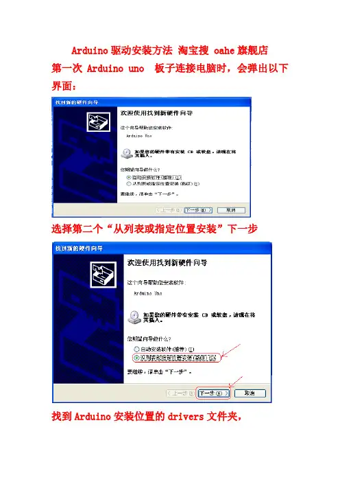
Arduino UNO驱动安装方法
- 格式:doc
- 大小:159.50 KB
- 文档页数:3
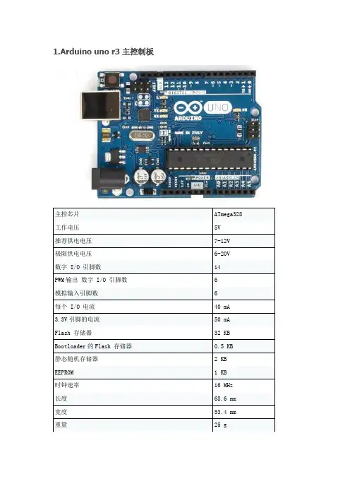
1.Arduino uno r3主控制板主控芯片ATmega328 工作电压5V推荐供电电压7-12V极限供电电压6-20V数字 I/O 引脚数14PWM输出数字 I/O 引脚数 6模拟输入引脚数 6每个 I/O 电流40 mA3.3V引脚的电流50 mA Flash 存储器32 KB Bootloader的Flash 存储器0.5 KB静态随机存储器 2 KB EEPROM 1 KB时钟速率16 MHz长度68.6 mm 宽度53.4 mm 重量25 gArduino uno r3主控制板的GRBL引脚定义2.A4988步进电机驱动模块输入电压8~35V最小驱动电压8V,输出驱动能力最大35V ,2A。
功能及优点∙低RDS(开)输出∙自动电流衰减模式检测/选择∙混合与慢电流衰减模式∙对低功率耗散同步整流∙内部UVLO∙交叉电流保护∙ 3.3 及5 V 兼容逻辑电源∙过热关机电路∙接地短路保护∙加载短路保护∙五个可选的步进模式:全、1/2、1/4、1/8 及1/16A4988引脚定义3.arduino cnc shield V3 扩展板输入电压范围12~36V。
GBRL专用cnc模块,完全兼容GBRL的arduino uno r3接口和A4988步进电机驱动模块接口。
引脚定义细分设置扩展板共划分为4个步进电机安装区域,每个区域设置相同。
使用跳线帽将对应两个排针短接。
0代表不短接,1代表短接。
M0M1M2细分000全细分1001/2细分0101/4细分1101/8细分1111/16细分这里推荐1/16细分,因为在进行激光雕刻时,速度比较慢,步进电机低速震动较大,需要更高的细分降低震动。
4.继电器模块控制信号5V,光耦隔离,带常开、常闭(可实现高、低电平触发)或直接高低电平触发,带安装孔。
继电器最大输出:直流30V/10A,交流250V/10A引脚定义如图3.2.2 模块接线主控制器-扩展板-驱动板堆叠主控制器堆叠上扩展板插上细分跳线帽插上驱动板X轴双驱,接法连线图。

Arduino Uno Rev3 SMDModel:A000073User ManualProgramming:The Arduino Uno can be programmed with the (Arduino Software (IDE)). Select "Arduino/Genuino Uno from the Tools > Board menu (according to the microcontroller on your board). For details, see the reference and tutorials.∙On Rev1 boards: connecting the solder jumper on the back of the board (near the map of Italy) and then rese ing the 8U2.∙On Rev2 or later boards: there is a resistor that pulling the 8U2/16U2 HWB line to ground, making it easier to put into DFU mode.extra layer of protection. If more than 500 mA is applied to the USB port, the fuse willautomatically break the connection until the short or overload is removed.Differences with other boards:The Uno differs from all preceding boards in that it does not use the FTDI USB-to-serial driver chip. Instead, it features the Atmega16U2 (Atmega8U2 up to version R2) programmed as a USB-to-serial converter.Power:The Arduino Uno board can be powered via the USB connection or with an external power supply. The power source is selected automatically.External (non-USB) power can come either from an AC-to-DC adapter (wall-wart) or battery. The adapter can be connected by plugging a 2.1mm center-positive plug into the board's power jack. Leads from a battery can be inserted in the GND and Vin pin headers of the POWER connector.The board can operate on an external supply from 6 to 20 volts. If supplied with less than 7V,however, the 5V pin may supply less than five volts and the board may become unstable. If using more than 12V, the voltage regulator may overheat and damage the board. The recommended range is 7 to12 volts.The power pins are as follows:∙Vin. The input voltage to the Arduino/Genuino board when it's using an external power source (as opposed to 5 volts from the USB connection or other regulated power source). You can supply voltage through this pin, or, if supplying voltage via the power jack, access it through this pin.∙5V.This pin outputs a regulated 5V from the regulator on the board. The board can be supplied with power either from the DC power jack (7 - 12V), the USB connector (5V), or the VIN pin of the board (7-12V). Supplying voltage via the 5V or 3.3V pins bypasses the regulator, and can damage your board.We don't advise it.∙3V3. A 3.3 volt supply generated by the on-board regulator. Maximum current draw is 50 mA.∙GND. Ground pins.∙IOREF. This pin on the Arduino/Genuino board provides the voltage reference with which the microcontroller operates. A properly configured shield can read the IOREF pin voltage and select the appropriate power source or enable voltage translators on the outputs to work with the 5V or 3.3V.Memory:The ATmega328 has 32 KB (with 0.5 KB occupied by the bootloader). It also has 2 KB of SRAM and 1 KB of EEPROM (which can be read and written with the EEPROM library).Input and Output:See the mapping between Arduino pins and ATmega328P ports. The mapping for the Atmega8, 168, and 328 is identical.Each of the 14 digital pins on the Uno can be used as an input or output,using pinMode(),digitalWrite(), and digitalRead() functions. They operate at 5 volts.Each pin can provide or receive 20 mA as recommended operating condition and has an internal pull-up resistor (disconnected by default) of 20-50k ohm. A maximum of 40mA is the value that must not be exceeded on any I/O pin to avoid permanent damage to the microcontroller.In addition, some pins have specialized functions:Serial: 0 (RX) and 1 (TX). Used to receive (RX) and transmit (TX) TTL serial data. These pins are connected to the corresponding pins of the ATmega8U2 USB-to-TTL Serial chip.External Interrupts: 2 and 3. These pins can be configured to trigger an interrupt on a low value, a rising or falling edge, or a change in value. See the attachInterrupt() function for details.PWM: 3, 5, 6, 9, 10, and 11. Provide 8-bit PWM output with the analogWrite() function.SPI: 10 (SS), 11 (MOSI), 12 (MISO), 13 (SCK). These pins support SPI communication using the SPI library.LED: 13. There is a built-in LED driven by digital pin 13. When the pin is HIGH value, the LED is on, when the pin is LOW, it's off.TWI: A4 or SDA pin and A5 or SCL pin. Support TWI communication using the Wire library.The Uno has 6 analog inputs, labeled A0 through A5, each of which provide 10 bits of resolution (i.e. 1024 different values). By default they measure from ground to 5 volts, though is it possible to change the upper end of their range using the AREF pin and the analogReference() function. There are a couple of other pins on the board:AREF. Reference voltage for the analog inputs. Used with analogReference().Reset. Bring this line LOW to reset the microcontroller. Typically used to add a reset button to shields which block the one on the board.Communication:Arduino/Genuino Uno has a number of facilities for communicating with a computer, another Arduino/Genuino board, or other microcontrollers. The ATmega328 provides UART TTL (5V) serial communication, which is available on digital pins 0 (RX) and 1 (TX). An ATmega16U2 on the board channels this serial communication over USB and appears as a virtual com port to software on the computer. The 16U2 firmware uses the standard USB COM drivers, and no external driver is needed. However, on Windows, a .in file is required. The Arduino Software (IDE) includes a serial monitor which allows simple textual data to be sent to and from the board. The RX and TX LEDs on the board will flash when data is being transmitted via the USB-to-serial chip and USB connection to the computer (but not for serial communication on pins 0 and 1).A SoftwareSerial library allows serial communication on any of the Uno's digital pins.The ATmega328 also supports I2C (TWI) and SPI communication. The Arduino Software (IDE) includes a Wire library to simplify use of the I2C bus; see the documentation for details. For SPI communication, use the SPI library.Automatic (Software) ResetRather than requiring a physical press of the reset button before an upload, the Arduino/Genuino Uno board is designed in a way that allows it to be reset by software running on a connectedcomputer. One of the hardware flow control lines (DTR) of the ATmega8U2/16U2 is connected to the reset line of the ATmega328 via a 100 nanofarad capacitor. When this line is asserted (taken low), the reset line drops long enough to reset the chip. The Arduino Software (IDE) uses this capability to allow you to upload code by simply pressing the upload button in the interface toolbar. This means that the bootloader can have a shorter timeout, as the lowering of DTR can be well-coordinated with the start of the upload.This setup has other implications. When the Uno is connected to either a computer running Mac OS X or Linux, it resets each time a connection is made to it from software (via USB). For the following half-second or so, the bootloader is running on the Uno. While it is programmed to ignore malformed data (i.e. anything besides an upload of new code), it will intercept the first few bytes of data sent to the board after a connection is opened. If a sketch running on the board receives one-timeconfiguration or other data when it first starts, make sure that the software with which itcommunicates waits a second after opening the connection and before sending this data.The Uno board contains a trace that can be cut to disable the auto-reset. The pads on either side of the trace can be soldered together to re-enable it. It's labeled "RESET-EN". You may also be able to disable the auto-reset by connecting a 110 ohm resistor from 5V to the reset line; see this forum thread for details.Revisions:Revision 3 of the board has the following new features:∙ 1.0 pinout: added SDA and SCL pins that are near to the AREF pin and two other new pins placed near to the RESET pin, the IOREF that allow the shields to adapt to the voltage provided from the board.In future, shields will be compatible with both the board that uses the AVR, which operates with 5V and with the Arduino Due that operates with 3.3V. The second one is a not connected pin, that is reserved for future purposes.∙Stronger RESET circuit.∙Atmega 16U2 replace the 8U2.。

NU-LINK DRIVER FOR ARDUINO ®IDE USER MANUALARM ® Cortex ®-M0 32-bit MicrocontrollerNuMicro ®FamilyNu-Link Driver for Arduino ®IDEUser ManualThe information described in this document is the exclusive intellectual property ofNuvoton Technology Corporation and shall not be reproduced without permission from Nuvoton.Nuvoton is providing this document only for reference purposes of NuMicro microcontroller based systemdesign. Nuvoton assumes no responsibility for errors or omissions.All data and specifications are subject to change without notice.For additional information or questions, please contact: Nuvoton Technology Corporation.NU-LINK DRIVER FOR ARDUINO® IDE USER MANUAL Table of Contents1Overview (3)2Arduino IDE Installation (4)3Hardware Setup (6)4NuEdu Evaluation Board Pin Out (8)NuEdu-M451 Board (8)4.1NuEdu-NUC240 Board (9)4.2NuEdu-NANO130 Board (10)4.3NuEdu-UNO Board (11)4.45Sample Code (12)NuEdu-M451 Board (12)5.1NuEdu-NUC240 Board (13)5.2NuEdu-NANO130 Board (14)5.3NuEdu-UNO Board (15)5.46Revision History (16)NU-LINK DRIVER FOR ARDUINO ®IDE USER MANUAL1 OVERVIEWArduino is an open-source electronics platform based on easy-to-use hardware and software. The NuMicro ®NuEdu-UNO Evaluation Board is an Arduino compatible hardware using NuMicro MCU as the microcontroller. Its function can be extended with Arduino add-ons. Users can use Arduino IDE to develop their applications and leverage large number of open source samples.Figure 1-1 NuEdu-UNO Board with Different Add-onsThe next chapter introduces the steps to install Arduino ®IDE and apply patch to support NuMicro NuEdu Evaluation Board.NU-LINK DRIVER FOR ARDUINO® IDE USER MANUAL 2 ARDUINO IDE INSTALLATIONPlease follow the steps below to install Arduino® 1.5.8 IDE and apply patch to support NuMicro MCU. Refer to Arduino official website for the usage of Arduino® IDE.Figure 2-1 Download Arduino ® 1.5.82.Extract arduino-1.5.8-windows.zip to the installation path.Figure 2-2 Extract Arduino® 1.5.8NU-LINK DRIVER FOR ARDUINO ®IDE USER MANUAL3. Double-click NuMicro Arduino patch (NuMicro_Patch_For_Arduino1.5.8.exe), and input theFigure 2-3 Install NuMicro Arduino Patch4. After successfully applying the patch, five board names NuEdu-M451, NuEdu-NUC240,NuEdu-NANO130, NuEdu-UNO, and NuMaker-TRIO can be found in Arduino IDE as shownFigure 2-4 Installation CompleteNU-LINK DRIVER FOR ARDUINO® IDE USER MANUAL 3 HARDWARE SETUPThe Arduino® IDE consists of source code editor, project build tool and also supports firmware download and UART debug function. To download firmware to NuEdu evaluation board, PC must be connected with the on-board Nu-Link Me using USB cable. The NuEdu Evaluation Board can print out debug message through the USB virtual COM (VCOM) interface.Figure 3-1 NuEdu-UNO Hardware SetupFigure 3-2 USB Connection on NuEdu-UNONU-LINK DRIVER FOR ARDUINO ®IDE USER MANUALThe VCOM function can be used in Arduino IDE, Keil and IAR. To enable VCOM function on Nu-Link Me, all SW2 pins need to turn to ON position. Otherwise, turn pin2~4 to OFF position. For the usage of different NuEdu Evaluation Boards, please refer to the user manual respectively.Figure 3-3 Switch Default as UART ModePin Name Disable VCOMNU-LINK DRIVER FOR ARDUINO® IDE USER MANUAL 4 NUEDU EVALUATION BOARD PIN OUTThis chapter shows the pin out of different NuEdu Evaluation Boards.NuEdu-M451 Board4.1Figure 4-1 NuEdu-M451 Pin OutNU-LINK DRIVER FOR ARDUINO ®IDE USER MANUALNuEdu-NUC240 Board4.2Figure 4-2 NuEdu-NUC240 Pin OutNU-LINK DRIVER FOR ARDUINO® IDE USER MANUALNuEdu-NANO130 Board4.3Figure 4-3 NuEdu-NANO130 Pin OutNU-LINK DRIVER FOR ARDUINO ®IDE USER MANUALNuEdu-UNO Board4.4Figure 4-4 NuEdu-UNO Pin OutNU-LINK DRIVER FOR ARDUINO® IDE USER MANUAL 5 SAMPLE CODENuEdu-M451 Board5.1The following table lists the Arduino samples which have been tested on M451 NuEdu board.NU-LINK DRIVER FOR ARDUINO ®IDE USER MANUALNuEdu-NUC240 Board5.2The following table lists the Arduino samples which have been tested on NUC240 NuEdu board.NU-LINK DRIVER FOR ARDUINO® IDE USER MANUALNuEdu-NANO130 Board5.3The following table lists the Arduino samples which have been tested on NANO130 NuEdu board.NU-LINK DRIVER FOR ARDUINO ®IDE USER MANUALNuEdu-UNO Board5.4The following table lists the Arduino samples which have been tested on NUC131 NuEdu board.NU-LINK DRIVER FOR ARDUINO® IDE USER MANUAL 6 REVISION HISTORY2014.11.10 1.00 1. Initially issued.2015.3.20 1.01 1. Merged NuEdu-M451, NuEdu-NUC240, NuEdu-NANO130, NuEdu-UNO, and NuMaker-TRIO intothe same platform group.2. Updated sample list to include SernsorsKit_37in1samples.NU-LINK DRIVER FOR ARDUINO ®IDE USER MANUALImportant NoticeNuvoton Products are neither intended nor warranted for usage in systems or equipment, any malfunction or failure of which may cause loss of human life, bodily injury or severe property damage. Such applications are deemed, “Insecure Usage”.Insecure usage includes, but is not limited to: equipment for surgical implementation, atomic energy control instruments, airplane or spaceship instruments, the control or operation of dynamic, brake or safety systems designed for vehicular use, traffic signal instruments, all types of safety devices, and other applications intended to support or sustain life.All Insecure Usage shall be made at customer’s risk, and in the event that third parties lay claims to Nuvoton as a result of customer’s Insecure Usage, customer shall indemnify the damages and liabilities thus incurred by Nuvoton.。

UNO-S2 Keypad Installation ManualSAFETY INFORMATION UNO-S2 Keypad21.Read Instructions - All the safety and operating instructions should be read before the appliance is operated.2.Retain Instructions - The safety and operating instructions should be retained for future reference.3.Heed Warnings - All warnings on the appliance in the operating instructions should be adhered to.4.Follow Instructions - All operating and user instructions should be followed.5.Water and Moisture - The appliance should not be used near water; for example, near a bathtub, washbowl, kitchen sink,laundry tub, in a wet basement, or near a swimming pool.6.Wall or ceiling Mounting - The appliance should be mounted to a wall or ceiling only as recommended by the manufacturer.7.Ventilation - The appliance should be situated so that its location or position does not interfere with its proper ventila-tion. For example, the appliance should not be situated on a bed, sofa, rug, or similar surface that may block the ventila-tion openings, or placed in a built-in installation, such as a bookcase or cabinet that may impede the flow of air through the ventilation openings.8.Heat - The appliance should be situated away from heat sources such as radiators, heat registers, stoves, or other appli-ances (including amplifiers) that produce heat.9.Power Sources - The appliance should be connected to a power supply only of the type described in the operatinginstructions or as marked on the appliance.10.Grounding or Polarization - Precaution should be taken so that the grounding or polarization means of an appliance is notdefeated.11.Power Cord Protection - Power supply cords should be routed so that they are not likely to be walked on or pinched byitems placed upon or against them, paying particular attention to cords at plugs, receptacles, and the point where they exit from the appliance.12.Object and Liquid Entry - Care should be taken so that objects do not fall and liquids are not spilled into the enclosurethrough the openings.13.Damage Requiring Service - The appliance should be serviced by qualified service personnel when: the power supply cordor the plug has been damaged; or objects have fallen, liquid has been spilled into the appliance; or the appliance has been exposed to rain; or the appliance does not appear to operate normally; or the appliance has been dropped or the enclosure is damaged.14.Servicing - The user should not attempt to service the appliance beyond that described in the operating instructions. Allother servicing should be referred to qualified service personnel.Precautions:1.Power – WARNING: BEFORE TURNING ON THE POWER FOR THE FIRST TIME, READ THE FOLLOWING SECTION CAREFULLY.All models are designed for use with either AC120V, 60Hz or AC240, 50Hz voltages. The unit will autoswitch to either of these voltages.2.Do Not Touch The UNO-S2 With Wet Hands – Do not handle the unit or power cord when your hands are wet or damp. Ifwater or any other liquid enters the cabinet, take the UNO-S2 to a qualified service person for inspec tion.3.Care – Periodically wipe off the front and side panels of the cabinet with a soft cloth. Do not use rough material, thin-ners, alcohol or other chemical solvents or cloths since this may damage the finish or remove the panel lettering.TABLE OF CONTENTSUNO-S2 Keypad Front Panel..............................................................................................4-5 Operation. (6)User Menu................................................................................................7-8 Settings (9)Update Port (10)Rear Panel (11)Keypad Connections..............................................................................12-13 Keypad Diagnostics Menu......................................................................14-15 Keypad Firmware Update......................................................................16-17 Keypad Location..................................................................................18-19IR Receiver Connection (20)Technical Specifications (21)Warranty..............................................................................................22-233USER GUIDEUNO-S2 Keypad Front Panel4USER GUIDEUNO-S2 Keypad Front Panel5LCD PANEL - 12-character backlit display shows status of the room, source,volume, and moreSOURCE SELECT BUTTON - Scrolls through the sources directly connected to the CAV6.6/CAM6.6. Press and hold brings up the USER MENU for Loudness, Bass,Treble, etc.VOLUME UP/DOWN BUTTONS - Raises and lowers the volume for the room IR RECEIVER - Receives IR signals and passes them to the controller and source equip-ment. Also used when operating the UNO Keypad by using the SRC2 remote COMMAND KEYS - Pressing the command keys controls the source equipment POWER BUTTON - Turns room ON or OFF when pressed once, press and hold a second time will turn on or off all CAV6.6/CAM6.6 roomsF1 AND F2 BUTTONS - Selects Favorite 1 or Favorite 2 - preset user-selected favorite settings per room3246715USER GUIDEUNO-S2 Keypad Operation6MODE:“DND”- Do Not Disturb“SHARED”- Same source selected in multiple rooms“SYS ON”- Indicates system on“PARTY”- Party Mode enabled“MASTER”- Master Keypad in Party Mode12-character displayVolume IndicatorIndicates the middle of setting range1423USER GUIDEUNO-S2 Keypad User Menu7Zone On/Offto turn on the UNO System Keypad. This also turns on the cor-responding CAV6.6/CAM6.6’s room, and any presets previously assigned will be activated, including settings for bass, vol-to turn off the UNO System Keypad. This will also put the correspon-ding CAV6.6/CAM6.6’s room into a stand-by state.System All On/Offand holding for 3 seconds, after an ini-tial room has been turned on. An “All Off”after the room has been turned off.System On Indicatoris illuminated by a green backlight and the "SYS ON" iconremains visible.Source Select Buttonscrolls through the six A/V source sources are sequentially selected, each source's name appears on the keypad LCD panel. When a source is selected in more than one room, the “SHARED” icon will is also used to enter the User Menu with a press and hold action. (See next page for User Menu)Volume Up/Down ButtonsF1 and F2 Buttons buttons are user favorite presets. These presets can be selected at any time to recall source selection, vol-ume, favorite channel, disc, etc. To store a favorite preset: first, adjust the room set-tings and select a source to be stored.continuedUSER GUIDEUNO-S2 Keypad User Menu8orbutton until SAVED is dis-played on the LCD panel. Now a press andrelease of the button will recall the favoriteto select a disc orchannel (e.g., channel 45). Wait for the key-pad to show the source name, then pressand hold the F1 or F2 within 15 seconds ofsetting the numeric selection to save thesetting.Command KeysThe command keys allow control of theselected source at the UNO Keypad. Thecommand keys are activated with a pressand release, or press and hold to accesssecondary functions.UNO-S2 User MenuThe User Menu allows the user to adjustthe audio properties and control functionsof a particular room.The following keys are used to navigateand make changes while using the UserMenu:T o exit the User Menu, press and releaseAdjust feature setting (increment).Adjust feature setting (decrement).The following features make up the UserMenu:ONPARTYUSER GUIDEUNO-S2 Keypad Settings9Feature and Setting:1. BASS -10 < Bass:Flat > +102. TREBLE -10 < Treble:Flat > +103. LOUDNESS (more bass, fuller sound)On or Off4. BALANCE Left -10 < Center > Right +105. TURN ON VOL (default room volume level)0 to 1006. BG COLOR (keypad background light)Amber or Green or Off7. DO NOT DSTRB -On or Off (default)Do Not Disturb means do not disturb this room or selected source. This stops pages from being sent to this room, stops an “All Off," "All On" or Party Mode command from affecting this room. When another UNOSystems Keypad selects the same source, a DND icon will appear alerting the user the source is in Do Not Disturb mode. 8. PARTY MODE - Master (Enable/Disable)When in “PARTY MODE” the system is primari-ly controlled by a “MASTER” Keypad. Party Mode links all rooms to the same source which is selected by the Master Keypadroom. Any keypad in the system can become a Master Keypad (if enabled) but only one Master Keypad may exist at a time in Party Mode. Selecting Master Keypad mode from another keypad will transfer Master Keypad control to that room and release it from the first. When the source selected in the Master Keypad room is changed then the source for all rooms changes as well.Volume level changes at the Master Keypad will be reflected in all rooms in Party Mode.Non-Master zones in Party Mode can tem-porarily override Master Keypad volume level adjustments for their particular room prefer-ence. F1 and F2 favorite presets selected from the Master Keypad will be enabled in all rooms in Party Mode. Master Keypad will not change Bass, Treble, or Loudness adjust-ments for any other rooms other than the Master Keypad room. Every other keypad will still operate its respective bass, treble, bal-ance and loudness adjustments for that room. 9. FRONT (AUX) A/V IN - Enabled/Disabled Allows the system to select a seventhsource option through the controller's front panel AUX connection for use with cam-corders, game consoles, etc.10SETUP BUTTON - Activates Installer Setup Mode for the UNO-S2 keypad OS UPDATE PORT - Port used for UNO keypad OS software updates12INSTALLER GUIDEUNO-S2 Keypad Rear Panel11EXTERNAL IR RECEIVER IN CONNECTOR - Connection for external IR Receiver OS UPDATE JUMPER - Selects “Run” or “OS Update” mode RESET BUTTON - Reset whenever changing from RUN to OS update110 PUNCHDOWN CONNECTOR - Termination for CAT-5 connection between the UNO-S2 Keypad and the CAV6.6/CAM6.6 controller1234INSTALLER GUIDEUNO-S2 Keypad Connections12INSTALLER GUIDE UNO-S2 Keypad ConnectionsCAT-5 ConnectionThe UNO-S2 Keypad uses a 110-punch-down terminal to provide a simple installation and strong connection for CAT-5 cable’s eight conductors. Punchdown terminals require the use of a punchdown tool which has been pro-vided with the keypad kit. Attach the CAT-5 cable to the 110-punchdown ter-minal on the UNO-S2 Keypad as shown, matching the conductor colors to the connection color guide. The keypad will not operate properly if the terminations deviate from the required connection order.Take care when using an impact 110 punchdown tool, as this may overspread the contact points. Use of the impact tool may propel stray bits of wire and jacket into the keypad’s chassis and possibly cause a short in the circuitry. Gently shake or blow air through the keypad chassis to remove stray wire before the keypad is installed into the junction box.OS Update PortThe OS Update Port is is used to update the UNO-S2 Keypad operating system software in the future. When an update is released, it will be available online through the Document Center at.Look for the Technical Documents under Multi-source/Multi-room products. The Programming Cable is available from Russound, Part #2500-121036. Jumper SettingThe jumper settings on the back of the UNO-S2 Keypad can be set for “Run” and “OS Update.” The jumper setting must be in the “Run” position before the keypad is mounted into the junction box, and must remain set in “Run” to operate the key-pad. The jumper will be set to “OS Update” only while updating the keypad’s operating systems.Caution13INSTALLER GUIDEUNO-S2 Keypad Diagnostics Menu14The Diagnostics Menu allows theinstaller to run a diagnostic checkon the keypad and to verify thefirmware version. The DiagnosticsMenu also contains the updatefirmware procedure for updatingthe UNO-S2’s firmware.To access the Diagnostics Menu,press and hold the Setup buttonon the right side of the keypaduntil “DIAGNOSTICS” appears onthe display. The menus are out-lined in the diagram on the nextpage.When finished, press and releasethe Setup button again (except forthe Update Firmware where thepower must be cycled).Note:Do not change Controller IDsettings in this menu. Controller IDis set in the Controller SetupMenu of the controller only.INSTALLER GUIDEUNO-S2 Keypad Diagnostics Menu15INSTALLER GUIDEUNO-S2 Keypad Firmware Update16INSTALLER GUIDEUNO-S2 Keypad Firmware Update17INSTALLER GUIDEUNO-S2 Keypad Location18INSTALLER GUIDEUNO-S2 Keypad Location Installation LocationThe best infrared remote performance is achieved with the keypad installed away from any direct sunlight, plasma TV, and low voltage lighting controls. Also consid-er convenience when choosing a location. Choose a place that is easily seen from the position where a person is most likely to be located.Check whether or not you can route the wire to the location you have chosen. Keypad InstallationTo install a double-gang keypad, you will need to use a 36 ci UL/CSA approved plastic double-gang electrical box.Route CAT-5 wire to the junction box fromthe CAV6.6/CAM6.6.Use the supplied 110 punchdown toolto connect each wire to its correspon-ding color labeled on the punchdownterminal (See page 12 for details).Ensure jumper setting on the keypad isin the “RUN” position.Mount the keypad in the electrical boxand attach the cover plate. Repeat thesteps until all keypads are installed.19INSTALLER GUIDEIR Receiver ConnectionBack ofUNO-S220TECHNICAL SPECIFICATIONSUNO-S2 Keypad SpecificationsDimensions: 3.65"W x 1.125"D x 4.3"H(9.2 x 10.9 x 2.8 cm)Fits 2-Gang UL/CSA Approved Work BoxWeight:9 oz. (255 g)Power Requirements:12 VDC 180mACAT-5 Connection:110 punchdownAll trademarks are the property of their respective owners.21WARRANTY22Warranty RepairThe Russound UNO-S2 is fully guaranteed against all defects in materials and workman-ship for two (2) years from the date of purchase. During this period, Russound will replace any defective parts and correct any defect in workmanship without charge for either parts or labor.For this warranty to apply, the unit must be installed and used according to its written instructions. If service is necessary, it must be performed by Russound. The unit must be returned to Russound at the owner's expense and with prior written permission. Accidental damage and shipping damage are not considered defects, nor is damage resulting from abuse or from servicing by an agency or person not specifically authorized in writing by Russound.This Warranty does not cover:• Damage caused by abuse, accident, misuse, negligence,or improper installation or operation•Power surges and lightning strikes•Normal wear and maintenance•Products that have been altered or modified•Any product whose identifying number, decal, serial number, etc.has been altered, defaced or removedWARRANTY Russound sells products only through authorized Dealers and Distributors to ensure that customers obtain proper support and service. Any Russound product purchased from an unauthorized dealer or other source, including retailers, mail order sellers and online sell-ers will not be honored or serviced under existing Russound warranty policy. Any sale of products by an unauthorized source or other manner not authorized by Russound shallvoid the warranty on the applicable product.Damage to or destruction of components due to application of excessive power voids the warranty on those parts. In these cases, repairs will be made on the basis or the retailvalue of the parts and labor. To return for repairs, the unit must be shipped to Russoundat the owner's expense, along with a note explaining the nature of service required. Besure to pack the unit in a corrugated container with at least three (3) inches of resilientmaterial to protect the unit from damage in transit.Before returning a unit for repair, call Russound at (603) 659-5170 for a ReturnAuthorization number. Write this number on the shipping label and ship to:RussoundATTN: Service ,5 Forbes Road, Newmarket, NH 03857Due to continual efforts to improve product quality as new technology and techniquesbecome available, Russound/FMP, Inc. reserves the right to revise system specificationswithout notice.23Russound5 Forbes Road, Newmarket, NH 03857tel 603.659.5170 • fax 603.659.5388e-mail:*****************28-1141 Rev. 4 11/30/05。