RAYCHEM电伴热系统施工及维护手册
- 格式:pdf
- 大小:8.69 MB
- 文档页数:91
SPECIFICATION GUIDELINEHOT WATER TEMPERATURE MAINTENANCESPECIFICATION GUIDELINEHOT WATER TEMPERATURE MAINTENANCES12 – Hot Water ServicesApplication: Domestic Hot Water Services (DHWS)nVent RAYCHEM - HWAT-M system complete with HWAT-Eco controller, SBS-xx-HV-ECO-10 control panel, or ACS-30 control & Monitoring system and RAYCHEM cold applied RayClic connection devices.The RAYCHEM HWAT-M hot water temperature maintenance system will provide a constant maintenance temperature of 50-55°C across a single pipe hot water distribution system.The Product shall be manufactured, supplied and delivered by:nVent Ltd.3 Rutherford RoadStephenson Industrial EstateWashington, Tyne & WearNE37 3HXTel (UK): 0800 969 013Tel (Ireland) 1800 654 241E-mail (UK): ************************E-mail (Ireland): *****************The heating cables shall be specifically designed for this application and shall comply with HSEHS (G) 70 as does the RAYCHEM Hot Water Maintenance System by nVent.The heating cables shall be capable of demonstrating a lifetime in excess of 40 years and have been used for this application for at least 20 years.The heating cables and accessories shall be warranted for a minimum of 10 years, with the control devices being warranted for a minimum of 2 years. When installed by nVent or by a trained Certified Pro installer (named by the manufacturer), a 12 Year Warranty on heaters and accessories and 6 Years on controls is applicable.The domestic hot water supply has been designed as a single pipe system. No return pipes shall be fitted.All hot water service pipes shall be fitted with an energy efficient, self-regulating heating cable system, RAYCHEM HWAT-M, as manufactured by nVent, to compensate for heat losses and variably maintain pipe temperatures in the range 50-65°C.The self-regulating heating cables shall have modified polyolefin electrical insulation (radiation cross-linked, to ensure long life expectancy), laminated aluminium foil layer (for increased chemical ingress protection), tinned-copper braid and modified polyolefin over-jacket with metre marks for ease of installation. The self-regulating index of the heating cable shall be at least 0.25. The cable shall also comply with EN62395-1.SPECIFICATION GUIDELINEHOT WATER TEMPERATURE MAINTENANCEInterconnection and termination shall be with cold applied, insulation displacement connectors and gel type end seals, UV resistant, IP 68, 65°C rated, as manufactured by nVent and known as RayClic.Control of HWAT circuits shall be via an energy saving, programmable controller to provide adjustable maintained temperatures in the range 50-55°C, as manufactured by nVent. The controller shall have a boiler temperature sensor (i.e. HWS flow temp) and alarm system, 7-day programmable temperature/time function, integrated clock, pre-set specific building programs, Legionella prevention cycle capability, password protection, optical and acoustic alarm fault messages. Acceptable control solutions include: -RAYCHEM HWAT-ECO Controller-RAYCHEM SBS-xx-HV-ECO-10 Control Panel including electrical protection devices.-RAYCHEM ACS-30 Control & Monitoring system with centralized user interface and decentralized power and control modules.The HWAT cables shall be installed ‘straight traced’(i.e. not spirally wound), within their maximum circuit lengths, tested and commissioned strictly in accordance with the manufacturer’s instructions, preferably by a specialist installer named by the manufacturer. The commissioning report must be registered to gain benefit from the product warranty. The system should be installed to within 1000mm of each outlet or blending valve, or as close as is reasonably practicable, and in accordance with hot water maintenance regulations.Insulation selection and thickness shall be in strict accordance with the HWAT design guide, taking into account variations in ambient temperature, and must be applied without delay after the heating cable installation. Affix suitable “Electrically Traced” warning labels to the outer insulation, placed no less than 3m apart, on alternate sides of the pipe and visible from all sections.All HWAT circuits shall be controlled and monitored via an approved control solution including integrated MCB’s (BS EN 60898 type C or D) and RCD (30 mA sensitivity, tripping within 100 ms). All connections between the electrical supply, control panel and HWAT circuits shall be installed by an approved electrical contractor.SPECIFICATION GUIDELINEHOT WATER TEMPERATURE MAINTENANCEControl SystemsThe Single Pipe DHWS (HWAT) system shall be controlled by either of the following control solutions, selected in function of the size of the DHWS distribution system:-HWAT-ECO-SBS-xx-HV-ECO-10 Control Panel-ACS-30 Control and monitoring systemHWAT-ECO Control DeviceAll HWAT circuits shall be controlled via an energy saving, programmable controller to provide an adjustable maintained temperature and known as RAYCHEM HWAT ECO, manufactured by nVent.The controller shall have the following functions:-Adjustable maintenance temperatures in the range 50-55°C (or 55-65°C with HWAT-R cable)-Integrated power-off timer-Boiler temperature (HWS flow temp) tracking-Master/slave function for large hot water systems. One control unit (=Master) shall be programmable; the other control units (=slaves) shall automatically copy the master settings when connected to it. The master control unit shall have the facility to operate a further 8 slave units -BMS connection via a variable DC voltage (0-10V).-IP54 rated-9 editable built-in building specific programmes for temperature maintenance-Automatic summer/winter time and leap year correction programming-Visible and audible alarmSPECIFICATION GUIDELINEHOT WATER TEMPERATURE MAINTENANCESBS-xx-HV-ECO-10 Control PanelAll hot water temperature maintenance trace-heating circuits shall be controlled and monitored via an integrated electrically protected, multi circuit control panel, SBS-xx-HV-ECO-10, by nVent.The HWAT panel shall provide control and monitoring functionality for a multiple circuit single pipe hot water temperature maintenance system including the provision of all electrical and circuit protection devices for safety purposes. The electrical panel shall be approved for use with the HWAT system and be certified for use by nVent.The control panel shall be available, as standard, in the following variants:SBS-03-HV-ECO-10 (Control & monitoring for up to 3 circuits)SBS-06-HV-ECO-10 (Control & monitoring for up to 6 circuits)SBS-09-HV-ECO-10 (Control & monitoring for up to 9 circuits)The panel shall comprise an integrated power load management algorithm to avoid peak power loading.The control and monitoring panel shall have, as a minimum:EN60204-1 and EN60439-1 compliance, CE approved for use with heat tracing systems.RAL7035 (Light Grey) Coated Metal Housing – IP54 rated.A volt free alarm contact to indicate:•RCD or circuit breaker failure mode•Loss of power indicator•Controller or sensor error detection modeA phased switch-on to allow peak load management. The phased switching should be managed by an integrated time-shift duty-cycle control method.An HWAT-ECO control unit as the central control device for standard heating and economy set-back mode programmable functions.Type C circuit protection and residual current device (30 mA rated) per heating circuit.Mounted terminal blocks for easy connection of the heating circuits within the panel.An integrated boiler output temperature sensor for HWS flow temperature tracking capability.All electrical connections between the electrical supply, control panel, and the heating circuits shall be carried out by an approved electrical contractor.SPECIFICATION GUIDELINEHOT WATER TEMPERATURE MAINTENANCEACS-30 Control & Monitoring SystemAll heat-tracing circuits shall be controlled and monitored via an electrically protected, multi circuit control solution, with an integrated centralised user interface terminal (UIT), known as RAYCHEM ACS-30, from by nVent. The UIT shall include 3 customisable alarm outputs forcustomer specification.The control & monitoring (C&M) system shall provide control and monitoring functionality for a multiple circuit heat-tracing system including the provision of all electrical and circuit protection devices.The Control system shall be certified and approved by the manufacturer for use with the heat-tracing system. The C&M system shall be modular for easy design and shall comprise some or all of the following product modules:ACS-30-EU-UIT2 Touch screen colour user interface terminal for control and monitoring of up to 260 individual circuits (Always included in the system).ACS-30-EU-PCM2 power & control modules which include integrated control & monitoring capability and electrical safety for equipment personnel and circuit protection switchgear. The power & control module will also include 5, 10,or 15 heating circuit capability, dependent upon selection, and will include an input (temperature sensor or external device) per circuit for individual heater circuit temperature monitoring (At least one PCM shall be included in the system).ACS-30-EU-Moni-RMM2-E remote monitoring module for the addition of 8 resistance temperature detectors (RTDs) for connection to the ACS-30-EU-PCM or to the - ACS-30-EU-UIT2. Up to 16 RMM modules may be controlled via a single User interface Terminal (UIT).The control system shall be capable of controlling and monitoring up to 260 individual circuits of heat-tracing via a centralised user interface terminal (UIT) for easy system monitoring.The heating circuit power and control modules (PCM) shall be modular, decentralised solutions to enable placement throughout the building, or group of buildings, in proximity to the required heating system to limit the quantity of power cabling.The PCMs shall be connected to the UIT via RS-485 cable for communication, control & monitoring purposes. In the event of power failure or communication failure from the UIT, the PCM shall be capable of continued function for safety and system continuity.The C&M system shall be capable of monitoring circuit by circuit line or ambient temperature, energy consumption, energy usage pattern, and ground fault/earth fault detection. There shall be an alarm function on a circuit by circuit basis. In the event of an alarm, the UIT shall provide details of the alarm reason as well as indicating the specific circuit(s) affected, with the event captured automatically in the event log in the UIT.The control system shall be compliant with European norm EN60439-1 and be tested and CE approved to this standard.SPECIFICATION GUIDELINEHOT WATER TEMPERATURE MAINTENANCEAll UIT and PCM units shall be RAL7035 (light grey) coloured metal enclosures for hard wearing durability. Type C circuit protection and residual current device (30mA rated) shall be included in the PCM per heating circuit. All electrical connections between the electrical supply, UIT, power & control modules, ancillaries, and heating circuits shall be carried out by a qualified and approved electrical contractor.In Engineering Notes ColumnThe domestic hot water supply has been designed as a single pipe DHWS. No return pipes shall be fitted in order to minimise heat loss and improve energy efficiency.All hot water service pipes shall be fitted with the energy efficient, self-regulating heating cables, RAYCHEM HWAT-R, as manufactured by nVent to maintain an adjustable temperature in the range 50-65°C.Termination of the self-regulating heating cables shall be with insulation displacement type connectors and gel type end seals, Rayclic, as manufactured by nVent.The circuits shall be controlled via an energy saving, programmable controller, HWAT ECO*, SBS-xx-HV-ECO-10*, or ACS-30* (*delete as appropriate), as manufactured by nVent, to provide adjustable temperatures in the range 50-65°C.The HWAT cables shall be installed ‘straight traced’ (i.e. not spirally wound), insulated, tested and commissioned strictly in accordance with the HWAT design guide and preferably by nVent or a specialist installer named by them.The cables shall be installed to within 1000mm of each outlet or blending valve, or as close to the draw-off point as is reasonably practicable.Insulation selection and thickness shall be in strict accordance with the HWAT design guide.SPECIFICATION GUIDELINEHOT WATER TEMPERATURE MAINTENANCEAppendix A.UKTel 0800 969 013Fax 0800 968 624************************IrelandTel 1800 654 241Fax 1800 654 240*****************Our powerful portfolio of brands:CADDY ERICO HOFFMAN RAYCHEM SCHROFF TRACER。

一.概述 (2)二.施工规范及依据 ......................... (4)三.施工方法及程序 (5)四.质量验收评定标准及验收方法 (9)五.HSE管理措施............................. .10概述温控伴热电缆(简称电缆)又称自调控电伴热线或自限温电热带。
它是一种电热功率随系统温度自调的带状限温伴热器。
即电缆本身具有自动限温,并随着被加热体系的温度变化能自动调整发热功率的功能,以保证工作体系始终稳定在设定的最佳操作温区正常运行。
1.1 工作原理温控伴热电缆的电热元件,是在两根平行金属母线之间均匀的挤包一层PTC材料(半晶高聚物与炭黑的共混物)制成的芯带。
PTC 材料经熔融挤出、冷却定型之后,分散其中的炭微粒形成无数纤细的导电炭网络。
当它们跨接在两根平行母线上时,就构成芯带的PTC 并联回路。
电缆一端的两根母线与电源接通时,电流从一根母线横向流过PTC材料层到达另一根母线形成并联回路。
PTC层就是连续并联在母线之间的电阻发热体,将电能转化成热能,对操作系统进行伴热保温。
当芯带温度升到相应的高阻区时,电阻大到几乎阻断电流的程度,芯带的温度将达到高限不再升高(即自动限温)。
与此同时,芯带通过护套向温度较低的被加热体系传热,达到稳态时单位时间传递的热量等于电缆的电功率。
电缆的输出功率主要受控于传热过程以及被加热体系的温度。
1.2 主要技术参数低温系列性能参数—标准颜色:黑色—温度范围:最高维持温度65C最高曝露温度85 C最高表面温度85C—施工温度:最低-60 C—热稳定性:由10C至99C间来回循环300次后,电缆发热量维持在90% 以上。
—弯曲半径:20C室温时,为25.4mm -30C低温时,为35mm—绝缘电阻:伴热电缆长度100m环境温度75C时,绝缘电阻最小值为20M D。
中温系列性能参数—标准颜色:褐色—温度范围:最高维持温度105C最高曝露温度135C最高表面温度135C—施工温度:最低-30 C—热稳定性:由10C至149C间来回循环300次后,电缆发热量维持在90%以上—弯曲半径:20C室温时,为25.4mm -30C低温时为35mm—绝缘电阻:伴热电缆长度100m,环境温度75C时,绝缘电阻最小值为20 M Q。
INTRODUCTIONThe HWAT system is a hot water temperature maintenance system that utilizes an electronic controller, self-regulating electric heating cables, and an easy-to-install set of connection kits to provide commercial buildings with immediate hot water at the tap without the use of a water recirculation system.Recirculation systems require the water heater temperature to be at least five degrees above the maintain temperature to compensate for the heat that is lost in the recirculation loop. With HWAT systems, the water in the supply pipe is maintained at a constant temperature along the entire length of the supply pipe so heating the water above the maintain temperature is not required. Recirculation systems also require return lines, pumps, and balancing valves, all of which are all unnecessary with HWAT.A key component of the HWAT system is the HWAT controller. In addition to providing flexible temperature control, the controllers provide energy savings; a heat-up cycle that increases the water temperature in stagnant pipes; Building Management System (BMS) interface; alarm relay to signal power, temperature, or communication problems; a water heater sensor function; and nine predefined programs that can be customized by the user.This step-by-step design guide provides the tools necessary to design a nVent RAYCHEM Hot Water Temperature Maintenance System (HWAT). For additional information, contact your nVent representative or call (800) 545-6258. Also, visit our website at /RAYCHEM .Table of ContentsINTRODUCTION .................................................................................... 1Typical Applications ............................................................................................................. 2Approvals and Code Compliance ..................................................................................... 2Safety Guidelines .................................................................................................................. 2Ground Fault Protection ...................................................................................................... 3Scald Protection ................................................................................................................... 3Design Requirements .......................................................................................................... 3SYSTEM OVERVIEW .............................................................................. 3HWAT Electronic Controllers ............................................................................................. 4HWAT Heating Cables ......................................................................................................... 4RayClic, FTC and HWT Connection Kits ......................................................................... 5DESIGN GUIDELINES ............................................................................ 5Before You Begin (6)Hot Water Temperature Maintenance –HWAT SystemTypical ApplicationsThe HWAT system is designed to be installed and operated in commercialbuildings. Table 1 shows typical HWAT applications, desired maintain temperatureswhen nVent RAYCHEM HWAT-P1 heating cable is used in conjunction with thenVent RAYCHEM HWAT-ECO-GF, or when nVent RAYCHEM HWAT-R2 heatingcable is used in conjunction with the nVent RAYCHEM HWAT-ECO-GF orACS-30 controllers.Table 1 Typical HWAT Applications* with HWAT-R2 only.This design guide covers standard HWAT applications which must meetthe following conditions:• Installed on copper or rigid plastic pipes• Insulated in accordance with the insulation schedule shown in Table 6• Powered at 120 V using HWAT-ECO-GF or at 208 - 277 V using the ACS-30 orHWAT-ECO-GF controller• Operated indoors where the ambient temperature is relatively constant andbetween 60°F (15°C) and 80°F (27°C)If your application does not meet the above conditions, contact yournVent representative for custom design assistance.Approvals and Code ComplianceThe HWAT system components are c-UL-us Listed, CSA Certified, and/orFM Approved in nonhazardous locations.HWAT-P1 and HWAT-R2 heating cables, RayClic and HWT connection kits are UL Listed, CSA certified andFM approved for use in non-hazardous locations. The FTC-HST-PLUS connection kit and the HWAT-ECO-GF controller are c-UL-us Listed and the ACS-CRM and the ACS-CRMS controllers are c-UL-us certified(ACS-UIT3) to US and Canadian standards for us in non-hazardous locations. Refer to the specific productdata sheets for details.The HWAT system is designed in accordance with the following international andnational codes:• International Plumbing Code• International Building Code• International Energy Conservation Code• National Standard Plumbing Code• National Electrical Code• Canadian Electrical Code• ANSI/ASHRAE Standard 188-2018 - Legionellosis: Risk Management for BuildingWater Systems• CIBSE TM13-2013 Minimising the Risk of Legionnaires DiseaseAdditionally, our HWAT solution has numerous state and local code approvals.Contact your nVent representative for further information. Due to its potentialto reduce energy usage and greenhouse gas emissions, HWAT solutions areeligible for LEED points.Safety GuidelinesThe safety and reliability of any heat-tracing system depends on the quality of theproducts selected and on proper design, installation, and maintenance. Incorrectdesign, handling, installation, or maintenance of any of the system componentscan cause underheating or overheating of the pipe or damage to the heating cablesystem and may result in system failure, electric shock, or fire. The guidelinesand instructions contained in this guide are important. Follow them carefully tominimize these risks and to ensure that the HWAT system performs reliably.Pay special attention to safety warnings identified as WARNING.Ground Fault ProtectionTo minimize the danger of fire from sustained electrical arcing if the heatingcable is damaged or improperly installed, and to comply with nVent requirements,agency certifications, and national electrical codes, ground fault equipmentprotection must be used on each heating cable branch circuit. Arcing may notbe stopped by conventional circuit breakers. The HWAT-ECO-GF and ACS-30controllers meet the electrical code requirements for ground fault equipmentprotection.Scald ProtectionHWAT systems present an increased risk of scalding due to the high water Array temperature. Pay special attention to the scald warning to the left.Design RequirementsTo comply with warranty requirements, the design and installation of the HWATsystem must be in accordance with this guide and the additional documentslisted below:• HWAT-ECO-GF Installation and Operations Manual (H60223)• HWAT System Installation and Operations Manual (H57548)• Rayclic Connection Kit Installation Instructions (H55388 and H55092)Installation documents are shipped with the respective products and are alsoavailable on our website at /RAYCHEM.SYSTEM OVERVIEWA complete HWAT system includes one or more HWAT-ECO-GF or ACS-30electronic controllers, HWAT-P1 or HWAT-R2 heating cable and nVent RAYCHEMRayClic connection kits. Fig. 1 illustrates a typical HWAT system. The keycomponents of the system will be described in this section.Fig. 1 Typical HWAT heating cable systemHWAT Electronic ControllersThe HWAT-ECO-GF electronic controller is designed for use with a single circuit ofHWAT-P1 or HWAT-R2 self-regulating heating cable. For large hot water systemsthe ACS-30 distributed controller is available, refer to the ACS-30 data sheet(H58261) for more information. The HWAT-ECO-GF provides a variety of featuresand control options, listed below, for your hot water temperature maintenancesystem.Fig. 2 HWAT-ECO-GF controller• Equipment rated ground fault protection built-in• Intuitive set-up and programming, includes a 5" inch color touch screen• Flexible temperature control of hot water temperature maintenance systems• Energy savings through an integrated function that lowers the maintaintemperature during hours of low water consumption• Heat-up cycle function that increases the water temperature of the hot waterin the pipes• Alarm relay to signal power, temperature or communication problems• Hot water storage and pipe temperature monitoring with high and lowtemperature alarms and automatic system shut down• Seven pre-defined building timer programs that can be customized by the user• Program in advance in power-off mode by using external power bank/chargerand USB connectionHWAT Heating CablesHWAT-P1 or HWAT-R2 self-regulating heating cables are installed on hot watersupply pipes underneath standard pipe insulation. The heating cable adjusts itsFig. 3 HWAT heating cableHWAT heating cables provide the following features:• Adjust power output to reduce the variations in water temperature • Can be cut to length, spliced, teed, and terminated in the field • Designed for use with the HWAT-ECO-GF or ACS-30 controllerrRayClic, FTC and HWT Connection KitsThe RayClic connection system is a simple, fast, and reliable set of connection kits developed for use with HWAT self-regulating heating cables. RayClic connection kits reduce installation time, lowering the total installed cost of the HWAT system. nVent RAYCHEM HWT-P and FTC-HST-PLUS heat shrink kits may also be used.RayClic-PCAlternate lighted end sealFig. 4 RayClic connection kitsDESIGN GUIDELINESThis section describes the seven steps necessary to design an HWAT system:1 Select the heating cable 2 Lay out the heating cable3 Select connection kits and accessories4 Finalize circuit length5 Select control configurations6 Select thermal insulation7 Complete Bill of MaterialsTo assist you with the design, we will carry two design examples through this process. The example details are listed below each step in red.Example 1Example 2An elementary school where 115°F (46°C) is the desired maintain temperature and no heat-up cycle is required. Piping layout showsapproximately 300 ft of pipe with two branches at the same location.A medium security prison where 115°F (46°C) is the desired maintain temperature and a 140°F (60°C) heat-up cycle is required. Pipinglayout shows approximately 700 ft of pipe with two branches at different locations.Before You BeginBefore you begin designing your HWAT system, gather this necessary information:• Desired maintain temperature • Indoor ambient temperature • Supply voltage • Piping layout • Total pipe length • Pipe diametersStep 1 Select heating cableUse Table 2 to select the appropriate system temperature setting. For more information on heat-up cycles, refer to the HWAT-ECO-GF Installation and Operations Manual (H 60223) or ACS-30 Programming Guide (H 58692). Heating Cable Catalog NumberBefore beginning, take a moment to understand the structure underlying heating cable catalog numbers. You will refer to this numbering convention throughout the product selection process. Your goal is to determine the catalog number for the product that best suits your needs.Catalog number: HWAT -P 1 or R 2Voltage P 1 = 120 VR 2 = 208, 240, 277 VFig. 5 Heating cable catalog numberRecord the following information: • Desired maintain temperature (°F/°C) _____________• Indoor ambient temperature (°F/°C) _____________• Supply voltage (V) _____________• Heat-up cycle (Yes/No) _____________• Temperature (°F/°C)_____________Example: Heating Cable Selection Example 1 Example 2Desired maintain temperature 115°F (46°C) 115°F (46°C)Ambient temperature 70°F (21°C) 70°F (21°C)Supply voltage208 Vac208 VacHeat-up cycle required No Yes Heat-up cycle temperature n/a 140°F (60°C)Table 2 HWAT System Temperature Range* For additional information on heat-up cycles, refer to the “Expanded HWAT-ECO-GFElectronic Controller Capabilities” section of the HWAT-ECO-GF Installation and Operations Manual (H 60223).Heating Cable Selection ExampleHeating cable selected HWAT-R 2Step 2 Lay out the heating cableThe piping layout of your building may require more than one HWAT circuit. To determine the number of circuits, group your piping by maintain temperature and location, a step that may require you to consult the plumbing and/or electricalengineer. Calculate the total length of pipe in each group, allowing one foot of heating cable for each foot of pipe. The length of heating cable in each group must not exceed the circuit lengths listed in Table 3.In Step 4, you will calculate the additional cable required to install the connection kits. This will increase the total length of heating cable and may require the needfor additional circuits.Table 3 Maximum Circuit LengthNote: Assumes a minimum water temperature of 50°F (10°C) at startupExample: Lay out circuits Example HWAT heating cable selected HWAT-R 2Length of pipe 700 ft Number of circuits 2Circuit breaker size30 AmpStep 3 Select connection kits and accessoriesHWAT systems are approved and warranted only as a complete system. The appropriate RayClic, FTC or HWT connection kits must be used. Use Table 4 to select the connection kits and accessories necessary for your HWAT system. Refer to the RayClic Connection System data sheet (H 57545) and the FTC Heat Shrinkable Connection Kits Datasheet (H 58159) in the Technical Data section for more information on the products.The appropriate numbers of end seals are included with each connection kit.Table 4 Connection Kits and Accessories* To minimize cable waste, nVent recommends that one RayClic-S be ordered for every 500 feet of cable.Example: Select connection kits and accessories Example Piping layout determined that the following 2 RayClic-PC connection kits and accessories are required. 2 RayClic-T 14 GT-6670 ETLStep 4 Finalize circuit lengthAdditional cable is required for future access at each connection kit. Add the additional cable, as detailed in Table 5, to the estimated circuit lengths from Step 2. Confirm that the maximum lengths shown in Table 3 have not been exceeded. If your circuit lengths are greater than those shown, reconfigureyour heating cable layout to allow for additional circuits.Table 5 Additional Cable Required for Each Connection KitExample: Finalize circuit length ExampleCircuit 1* Circuit 2*Length of heating cable per circuit 350 ft 350 ft Additional cable required RayClic-PC 2 ft 2 ft RayClic-T3 ft 3 ft RayClic-X n/a n/aTotal length of heating cable required355 ft355 ft* In this example, the circuits were evenly divided. Equal circuit lengths are notrequired.Step 5 Select control configurationFor single circuit applications, choose the HWAT-ECO-GF controller. For multi-circuit applications, choose the ACS-30 controller.Example: Select control method Example 1 Example 2TypeIndividual circuit Multi-circuit Number of circuits 1up to 260ControllerHWAT-ECO-GF ACS-30Step 6 Select insulationSelect the size of thermal insulation from Table 6. You will need to know the length and diameter of each pipe used in your application.For pipes 1 1/4 inches and smaller, use insulation that is oversized by 1/4 inch to allow room for insulating over the heating cables. Table 6 specifies IPS (Iron Pipe Size) insulation, which has a greater inner diameter than CTS (Copper Tube Size) insulation.For pipes 3 inches and larger, the thickness of insulation can either be equal to the pipe diameter with a single heating cable or 1/3 the pipe diameter with two heating cables. For example, a 6 inch pipe with 6 inches of insulation and one run of heating cable is equivalent to a 6 inch pipe with 2 inches of insulation and tworuns of heating cable.Table 6 Fiberglass Insulation Selectionpipe diameter with one run of heating cable or 1/3 the pipe diameter with two runs of heating cable.Example: Select InsulationCopper pipe size (in)IPS insulation size (in)Insulation thickness (in)Example 13/41111 1/411 1/21 1/21 1/2Example 211 1/412222 1/22 1/22 1/2Step 7 Complete Bill of MaterialsYou are now ready to compile a Bill of Materials. Using the design results, detail each item as shown in Table 7 below. Fig. 5 illustrates a complete typical HWAT system./RAYCHEM | 11RAYCHEM-DG-H57510-HWATHotWaterTempMaint-EN-2210Fig. 7 Typical configuration for the ACS-30 system Table 7 Bill of Materials (Example)North AmericaTel +1.800.545.6258Fax +1.800.527.5703**********************©2022 nVent. All nVent marks and logos are owned or licensed by nVent Services GmbH or its affiliates. All other trademarks are the property of their respective owners.nVent reserves the right to change specifications without notice./RAYCHEM | 12。

20DESCRIPTIONThe nVent RAYCHEM SBS-XX-CM-20 control panel for ice andsnow prevention systems provides a totally integratedelectrical safety, connection and control solution for nVentRAYCHEM EM2-CM constant wattage heating mats for surfacesnow melting applications. The control panel comprises theVIA-DU-20 multi-sensor control unit for energy efficient groundsurface heating, and integrated electrical safety devices.The SBS-XX-CM-20 panels offer solutions up to 18 maximumcircuits of EM2-CM mats.The panel also includes electrical circuit protectiondevices (C-type circuit breakers) and residual current devices forsafety and peace of mind. The panels needonly be connected to the 400Vac (3 phase) supply. ADVANTAGESFast connection of multiple circuits directly into the control panel• No need for additional connections terminals–3-18 heating circuit can be connected and switched by a single panel–Circuit protection and safety devices integrated into the panel• No need for separate safety devices–Complete system from the manufacturer• System and components specifically selected for high performance ice and snow prevention system controlTECHNICAL DATAControl VIA-DU-20 multi-sensor control unitNominal Voltage (Un)400V (3 Phase)Rated voltage per heater circuit (Ue)230VSensor Ground temperature, moisture, and ambient temperature sensorsApproval CE (Approved to IEC61439)Supply Dependent on selected panel (25A-125A)RCD30mAAmbient temperatures +10ºC to +35ºCLine Circuit breakers20A (Type C) per 3 heater circuit groupInstallation Location IndoorExternal protection rating IP65Colour RAL 7035 (Grey)Enclosure type and material HOFFMAN Brand (nVent), Metal enclosureSelector switch Auto/Manual heating circuit switchingAlarm function1 general potential free alarm contact; alarm light indicator on panel front©2018 nVent. All nVent marks and logos are owned or licensed by nVent Services GmbH or its affiliates. All other trademarks are the property of their respective owners. nVent reserves the right to change specifications without notice.SBS CONTROL PANEL WEIGHT & DIMENSIONS TABLESBS-03-CM-2032600400210SBS-06-CM-2045600600210SBS-09-CM-2045600600210SBS-12-CM-2090800800210SBS-15-CM-2090800800210SBS-18-CM-201151000800300RELATED PRODUCTSThe SBS-XX-CM-20 control panel is compatible with the RAYCHEM EM 2-CM heating mats:RAYCHEM EM 2-CM heating mats (300W/m 2)GM-2XT (for drain line heating)**T he SBS-XX-CM-20 panel includes an additional circuit connection for drain heating capabilities at the edge of heated surfaces or at the lower end of ramps using GM-2XT heating cable (maximum drain line circuit length of 15m).PRODUCT REFERENCETo order the SBS-XX-CM-20 control panel, please reference:1244-006430SBS-03-CM-20Up to 3 Circuit control panel for EM 2-CM surface heating products 1244-006431SBS-06-CM-204-6 Circuit control panel for EM 2-CM surface heating products 1244-006432SBS-09-CM-20 7-9 Circuit control panel for EM 2-CM surface heating products 1244-006433SBS-12-CM-2010-12 Circuit control panel for EM 2-CM surface heating products 1244-008212SBS-15-CM-2013-15 Circuit control panel for EM 2-CM surface heating products 1244-008213SBS-18-CM-2016-18 Circuit control panel for EM 2-CM surface heating productsINSTALLATION INFORMATIONComplete panel wiring information and schematics are provided with the product. All electrical installations must be carried out by an approved electrician in compliance with local electrical requirements and norms.India - NoidaTel +91 120 464 9500Fax +91 120 464 9548*******************India - MumbaiTel +91 22 6775 8800/01Fax +91 22 2556 1491*******************UAETel +971 4 378 1700Fax +971 4 378 1777*******************United KingdomTel 0800 969 013Fax 0800 968 624************************IrelandTel 1800 654 241Fax 1800 654 240*****************South East AsiaTel +65 67685800Fax +65 67322263AustraliaTel +61 2 97920250Fax +61 2 97745931。
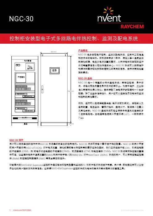
30产品概述和防冻中的电伴热。
该系统拥有多个部件,满足从单一温度监测到接地故障、电压及电流测量的需求,从而将电伴热回路的运行状况等重要信息从现场传递到中心。
NGC-30系统可以按照维护和操作所需将现场所获数据转化成有用的信息,进而将常规检查降到最低。
NGC-30盘柜NGC-30是一个完整的分布式盘柜系统。
其特征包括:易于访问、将电线预先布置在易于访问的端子上。
为便于维护,工业标准仪表箱布线得以优化。
面板装配了漏电保护断路器和一个主断路器。
除了这些标准特性外,用户还可以选择性添加电伴热监测和控制的其他需求。
例如,选项可以包括接触器类型 (电子式或机械式),回路数以及备用数量,电压监测,警报灯指示,盘柜尺寸,电缆接入位置以及其他参数。
NGC-30盘柜系统可包含使用专用通讯线连接的多个互联电路柜。
主柜通常包括用户界面终端 (UIT),一般安装于门上。
NGC-30组件用户可以购买单独的组件并将NGC-30系统集成到自己的控制柜内。
NGC-30系统可按客户需求进行相应配置。
NGC-30的用户界面即用户界面终端(NGC-UIT3-EX)。
对于电流测量、接地故障或者分布控制等的需求逐渐凸显时,我们应该选择卡柜 (CR),机械继电器的卡柜模块 (CRM)、和/或电子式继电器的卡柜模块(CRMS)、变流器模块 (CTM) 和电压模块 (CVM)。
NGC-30系统有两种远程测量模块可选,这些模块是用于温度测量的RMM2和用于数字输入的RMM2-DI。
对于MoniTrace 200N-E 系统的用户,可以使用远程监控模块 (RMM) 和远程控制器模块 (RMC) 等完全兼容的组件。
功能强大的RAYCHEM Supervisor监控软件通过电伴热控制配置和监测的PC 机软件包对系统进行完善。
用户端- 服务器应用可以让世界各地的用户随时访问所有信息。
这使得RAYCHEM Supervisor监控软件成为电伴热解决方案中强有力的管理工具。
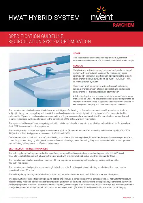
SCOPEThis specification describes an energy efficient system fortemperature maintenance of a domestic potable hot water supply.GENERALThe domestic hot water supply has been designed as a hybridsystem, with recirculation loops on the main supply pipesoptimised by the use of a self-regulating heating cable systemon all branch pipe run outs, known as nVent RAYCHEM HWATas manufactured by nVent.The system shall be complete with self-regulating heatingcables, advanced energy efficient controller and cold appliedcomponents for interconnection and termination.All electrical system components shall be sourced from a singlemanufacturer, under no circumstances shall any components beinstalled other than those supplied by the cable manufacturer, toensure system integrity and meet warranty requirements.The manufacturer shall offer an extended warranty of 10 years for heating cables and components and 2 years for controllers, subject to the system being designed, installed, tested and commissioned strictly to their requirements. The warranty shall be extended to 12 years on heating cables/components and 6 years on controls when installed by the manufacturer or by a trained installer recognised by them. All subject to the completion of the online warranty registration.The system shall be capable of being designed within a BIM model and the manufacturer shall provide a BIM add-in for Autodesk Revit MEP to automate the design process.The heating cables, controls and system components shall be CE marked and certified according to EN codes by BSI, VDE, CSTB, SEV, ÖVE and fulfil the hygiene requirements of DGVW and SVGW.Document submittal shall include all of the following: data sheets (for heating cables, interconnection/termination components and controller), system design guide, typical system schematic drawings, controller wiring diagrams, system installation and operation manual, along with approval certificates upon request.SELF-REGULATING HEATING CABLESThe self-regulating heating cables shall be specifically designed for this application, tested and approved to IEC 62395 andIEEE 515.1, suitable for use with 20A circuit breakers and with a minimum bend radius less than or equal to 10mm.The manufacturer shall demonstrate minimum 40 year experience in producing self-regulating heating cables and beISO-9001 registered.The manufacturer shall provide an extensive global reference list for this application, including installations that have been in operation for over 15 years.The self-regulating heating cables shall be qualified and tested to demonstrate a useful lifetime in excess of 40 years.The construction of the self-regulating heating cables shall include a conductive polymer core (qualified for hot water temperature maintenance), modified polyolefin electrical insulation (radiation cross-linked, to ensure long life expectancy), laminated aluminium foil layer (to protect the heater core from chemical ingress), tinned copper braid with minimum 70% coverage and modified polyolefin over jacket printed with cable model, batch number and metre marks (for ease of installation within maximum circuit length).[Select One Option][Option 1]The self-regulating heating cable shall be nVent RAYCHEM HWAT-R and provide pipe maintained temperatures in the range 50-65°C [Option 2]The self-regulating heating cable shall be nVent RAYCHEM HWAT-M and provide pipe maintained temperatures in the range 50-55°C INTERCONNECTION AND TERMINATION COMPONENTSInterconnection and termination shall be with cold applied insulation displacement connectors and gel type end seals, which are UV resistant, IP68 and 65°C rated, suitable for 2500Vdc insulation resistance test, with Torx head fittings for ease of installation and both audible & visual installation confirmation, known as RayClic, manufactured by nVent.THERMAL INSULATIONInsulation selection and thickness shall be strictly in accordance with the self-regulating heating cable system design guide,with variations in ambient temperature fully considered. Insulation sections shall be applied without delay after the heating cable installation, affixed with suitable warning labels less than 3 m apart on alternate sides and visible from all sections.ENERGY EFFICIENT, CONTROL SYSTEM[Select One Option](Option 1)Multi-Circuit, Multi-Application Distributed Digital Control SystemAll hot water temperature maintenance circuits shall be controlled and monitored using a centralised control system with distributed power and control modules, known as nVent RAYCHEM ACS-30, complete with integrated HWAT ECO, manufactured by nVent.The centralised control system shall provide pre-programmed parameters to provide concurrent control for heating cables used for hot water temperature maintenance, pipe freeze protection, flow maintenance, surface snow melting, roof and gutter de-icing and floor heating applications.The control & monitoring system shall be modular for easy design and include:[select some or all of the following product modules]User Interface Terminal (UIT): a colour touch-screen central user interface terminal for control and monitoring up to 260 heating cable circuits, known as ACS-30-EU-UIT2, manufactured by nVent [always included in the system]Power Connection Module (PCM): to provide distributed power connection, control and monitoring of heating cable circuits, and integrated electrical protection, known as ACS-30-EU-PCM2, manufactured by nVent [at least 1 PCM shall be included in the system, up to 52 PCMs may be connected to each UIT]Remote Monitoring Modules (RMM): to measure additional temperatures for control and monitoring of heating cable tracing circuits, known as ACS-30-EU-Moni-RMM2-E, manufactured by nVent [up to 16 RMM modules may be controlled via a single UIT, with up to 8 RTDs per RMM]The centralised control system shall have the following functions:Multiple circuit, multiple heating cable applicationsModular design and installation - to provide total flexibility, including any future building modificationsControl and monitoring of up to 260 heating cable circuits - through a single user interface terminal (UIT)Central programming through the UIT3 user programmable alarm relays for user specified communication of alarm conditionsProtoNode high performance protocol gateway connection to allow translation from native ModBus to BacNet protocols Distributed power control modules (PCMs) - for placement throughout the building or group of buildings, to provide power connection, circuit protection and integrated control & monitoring in proximity to all required heating cable applications and to limit the power cabling neededPCMs with 1 sensor input per circuit for individual circuit temperature monitoringRemote monitoring modules (RMMs) - to measure additional temperatures for control and monitoringRMMs with up to 8 additional resistance temperature detectors (RTDs)UIT communication with up to 52 PCMs and up to 16 RMMsPCMs shall additionally• Provide 5, 10 or 15 circuits with integrated electrical and circuit protection (either 20A or 32A)• Contain control logic circuitry to ensure continuity of heating cable operation in the event of power failure orcommunication failure with the UIT• Provide circuit by circuit monitoring of line or ambient temperature, energy consumption, energy usage pattern andground fault/earth fault detection• Enable circuit by circuit alarm function, with the UIT providing details of the alarm, the circuit(s) affected and capture automatically in the event log.• Connect to the UIT via RS-485 cable for communication, control & monitoring purposesThe control system shall be compliant with IEC61439 and be tested and CE approved to this standard.The integrated energy efficiency controller shall have the following functions:Adjustable maintenance temperatures in the range 50-65°CWater heater temperature sensor (HWS flow temp) and alarm systemIntegrated power off timer function with 7 day programmable temperature versus time function, 8 editable built-in building specific programs for temperature maintenance, thermal shock program (for use with HWAT R), automatic summer/winter time and leap year correctionVisible and audible alarm5" Colour touch screen user interfacePassword protectionIP54 rated(Option 2)Single Circuit, Single Application ControllerAll self-regulating heating cable circuits shall be controlled with an energy saving thermostat, known as HWAT-T55, manufactured by nVent.The controller shall have the following functions:Digital display for pipe temperature and alarmPipe sensing temperature control with preset temperatures (55°C or 50°C)Maximum circuit length 50m3 operation modes (ON/ECO/OFF)Built in timer for ECO modeDIN rail mountable (35mm)EXECUTIONDesign DeliverablesThe manufacturer shall be able to provide heat loss calculations and corresponding selection of self regulating heating cables with variations in ambient temperature and pipe size and thermal insulation fully considered, system layout and schematic drawings indicating power connections, tees and end seals, electrical schedules indicating cable length and circuit protection, controller configuration listing and wiring diagrams.Installation DeliverablesThe self-regulating heating cables shall be installed in accordance with the design plans, ‘straight traced’ (i.e. not spirally wound) within the manufacturers defined maximum circuit lengths, tested and commissioned strictly in accordance with the manufacturer’s instructions. Installation of thermal insulation shall be closely coordinated with the responsible sub-contractors.[Select One Option][Option 1]The system shall be installed, tested and commissioned by the manufacturer.[Option 2]The system shall be installed and tested by installers trained and recognised by the manufacturer and then commissioned by the manufacturer.[Option 3]The system shall be installed, tested and commissioned by installers trained and recognised by the manufacturer.[Option 4]The system shall be installed, tested and commissioned under periodical supervision by the manufacturer.Electrical ConnectionAll connections between the electrical supply, control panel and self-regulating heating cable circuits shall be installed by an approved electrical contractor. All self-regulating heating cable circuits shall be electrically protected by MCB (BS EN 60898 type C or D) and RCD (30 mA sensitivity, tripping within 100ms).ENGINEERING DRAWING NOTESThe domestic hot water supply has been designed as a hybrid system, with recirculation loops on the main supply pipes optimised by the use of a self-regulating heating cable system on all branch pipe run outs, known as nVent RAYCHEM HWAT as manufactured by nVent.Interconnection and termination shall be with cold applied insulation displacement connectors and gel type end seals, which are UV resistant, IP68 and 65°C rated, suitable for 2500Vdc insulation resistance test, with Torx head fittings for quality of closure and both audible & visual installation confirmation, known as RayClic, manufactured by nVent.The circuits shall be controlled via an energy saving, programmable controller[Select One](Option 1)ACS-30 as manufactured by nVent(Option 2)HWAT-T55 as manufactured by nVentThe self-regulating heating cables shall be installed in accordance with the design plans, ‘straight traced’ (i.e. not spirally wound) within the manufacturers defined maximum circuit lengths, tested and commissioned strictly in accordance with the manufacturer’s instructions. Installation of thermal insulation shall be closely coordinated with the responsible sub-contractors.Insulation selection and thickness shall be strictly in accordance with the self-regulating heating cable system design guide, with variations in ambient temperature fully. Insulation sections shall be applied without delay after the heating cable installation, affixed with suitable warning labels less than 3 m apart on alternate sides and visible from all sections.All connections between the electrical supply, control panel and self-regulating heating cable circuits shall be installed by an approved electrical contractor.©2018 nVent. All nVent marks and logos are owned or licensed by nVent Services GmbH or its affiliates. All other trademarks are the property of their respective owners. nVent reserves the right to change specifications without notice.AustraliaTel +61 2 97920250Fax +61 2 97745931United KingdomTel 0800 969 013Fax 0800 968 624************************India - NoidaTel +91 120 464 9500Fax +91 120 464 9548*******************IrelandTel 1800 654 241Fax 1800 654 240*****************India - MumbaiTel +91 22 6775 8800/01Fax +91 22 2556 1491*******************South East AsiaTel +65 67685800Fax +65 67322263UAETel +971 4 378 1700Fax +971 4 378 1777*******************。

电伴热运行可靠性性能分析及应用、电伴热应用情况介绍:电伴热作为给设备过冬提供保障的保温材料得到了广泛应用,个别作业区的冬防保温全部依赖电伴热带。
随着电伴热带的大量使用,电伴热带的安全平稳运行是冬季能否安全平稳运行的重要保障。
而电伴热出现了一系列问题,,也给冬季安全运行带来了极大的隐患。
运行时间越长出现的问题就越多,一方面要保障冬季安全运行就必须保障电伴热带的安全运行;另一方面电伴热带价格昂贵,增加了昂贵的成本。
如何确保电伴热带的安全平稳运行,已成为迫不及待的问题。
三、电伴热带运行中出现的问题:电伴热系统经过几年的运行后都会或多或少的出现下列问题:1)、安装不规所造成的各种问题:(1)、安装的电伴热带没有紧贴保温设备管壁安装,以及没有按规定方法缠绕(图1,图2),导致这些电伴热带没有起到伴热效果,无法达到需求的伴热效果。
、电伴热平稳运行的重要性:图1图22)、安装人员装保温层时,在打孔时,将伴热带打穿(图3),导致开关跳闸。
图33)、制做电伴热首头不合规范(图4),导致开短路跳闸。
图44)、电伴热安装未考虑防水,尾端进水(图5)短路,导致开关跳闸。
尾端进水短路图5(5)、施工人员在安装电伴热接线盒时,没考虑接线盒进水的进水的可能,造成接线盒进水结冰(图6),最终造成端子排短路。
进水接冰短路图6(6)、在包保温铁皮时,电伴热没有完全固定好,造成伴热带与保温铁皮相互磨损,最终造成伴热带破损(图7)短路。
破损图72)、同一根电伴热带出现一段热一段不热等现象。
3)、弯曲的电伴热出现了不热的现象。
4)、电伴热老化速度快。
5)、电伴热短路造成着火。
6)、使用时间长的电伴热带发热效果降低。
7)、电伴热接线盒容易进水,造成伴热工作不正常。
8)、安装时将绝缘层损坏。
四、问题分析自限式电伴热带内部都是相当于无数个发热电阻的并联回路(图8)组成自调控发热内芯。
从下图中的“冷、暖、热”区域可以看出在低温时导通路径增多,从而允许更大的电流流经母线,在高温时聚合物扩张,导通路径减少,从而减少了伴热线的功率输出(图9)。
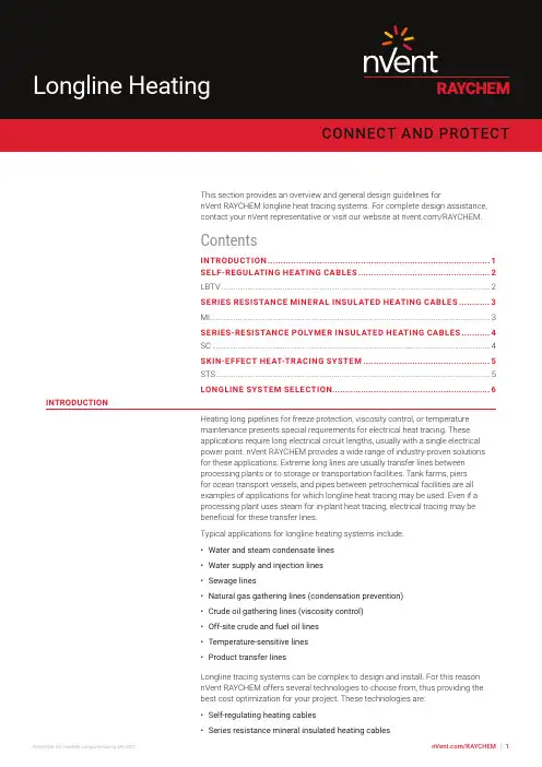
This section provides an overview and general design guidelines fornVent RAYCHEM longline heat tracing systems. For complete design assistance,contact your nVent representative or visit our website at /RAYCHEM.ContentsINTRODUCTION (1)SELF-REGULATING HEATING CABLES (2)LBTV (2)SERIES RESISTANCE MINERAL INSULATED HEATING CABLES (3)MI (3)SERIES-RESISTANCE POLYMER INSULATED HEATING CABLES (4)SC (4)SKIN-EFFECT HEAT-TRACING SYSTEM (5)STS (5)LONGLINE SYSTEM SELECTION (6)INTRODUCTIONHeating long pipelines for freeze protection, viscosity control, or temperaturemaintenance presents special requirements for electrical heat tracing. Theseapplications require long electrical circuit lengths, usually with a single electricalpower point. nVent RAYCHEM provides a wide range of industry-proven solutionsfor these applications. Extreme long lines are usually transfer lines betweenprocessing plants or to storage or transportation facilities. Tank farms, piersfor ocean transport vessels, and pipes between petrochemical facilities are allexamples of applications for which longline heat tracing may be used. Even if aprocessing plant uses steam for in-plant heat tracing, electrical tracing may bebeneficial for these transfer lines.Typical applications for longline heating systems include:• Water and steam condensate lines• Water supply and injection lines• Sewage lines• Natural gas gathering lines (condensation prevention)• Crude oil gathering lines (viscosity control)• Off-site crude and fuel oil lines• Temperature-sensitive lines• Product transfer linesLongline tracing systems can be complex to design and install. For this reasonnVent RAYCHEM offers several technologies to choose from, thus providing thebest cost optimization for your project. These technologies are:• Self-regulating heating cables• Series resistance mineral insulated heating cables• Series-resistance polymer insulated heating cables• Skin-effect tracing systems (STS)All longline heat tracing should be designed with engineering support from nVent.For assistance in selecting the best technology for the application, contact yournVent representative.SELF-REGULATING HEATING CABLESnVent RAYCHEM LBTVFig. 1 LBTV heating cableLBTV heating cables provide electrical freeze protection and temperaturemaintenance up to 150°F (65°C) for long piping systems in both nonhazardousand hazardous locations. This single-phase, self-regulating heating cableprovides freeze protection and low-temperature maintenance for medium-lengthapplications. The parallel circuit design results in a cable that can be cut to lengthin the field.Within the circuit length limitations, the heat output per foot is independent ofcircuit length. The cable is constructed with 10 AWG copper bus wires, permittinglonger circuit length with less voltage drop than the 16 AWG BTV cable bus wires.These heating cables maintain process temperatures up to 150°F (65°C) and canwithstand intermittent exposure to temperatures up to 185°F (85°C). They areapproved for use in nonhazardous and hazardous locations, including areas wherecorrosives may be present.Refer to the data sheets for more detailed information. Data sheets can be foundon /RAYCHEM, or the Technical data sheet section of the IndustrialHeat Tracing Solutions Products & Services Catalogue (H56550).Fig. 2 MI heating cablenVent RAYCHEM mineral insulated heating cables are used in longline applications where high maintain temperatures and/or high exposure temperatures exist, or high power output is required. MI heating cable is used in many applications, including transfer lines. It is rugged and economical, and can be used for lines up to 5000+ feet (1500+ m).A 600-Vac Delta or Wye electrical configuration balances the electrical load well. Designs must be done on a case-by-case basis because the total resistance must be matched to the transformer characteristics.Refer to the Mineral Insulated Cables design guide (H56884) for more detailed information.circuit lengths exceed the ratings of conventional parallel-resistance heating cables and a single power source is needed. Ohmic heating of the conductor provides the heat in this series circuit heating cable. Engineering design by nVent is required since the wattage output depends on the total circuit length and the voltage applied.SC cables are available in single-, double-, and triple-conductor configurations for single- or three-phase system designs. The resistance conductors are electrically isolated with high-temperature, heavy-wall fluoropolymers; a grounding braid; and a final fluoropolymer jacket. Maximum exposure temperatures are 400°F (204°C) for SC cables, 482°F (250°C) for SC/H cables, and 195°F (90°C) for SC/F cables. SC cables are capable of supporting circuit lengths up to 12,000 feet (3659 m) with one power supply point, and voltages up to 600 Vac.SKIN-EFFECT HEAT-TRACING SYSTEMnVent RAYCHEM STSFig. 4 Skin-effect Tracing System (STS)nVent RAYCHEM skin-effect tracing systems (STS) are custom engineered bynVent for each unique application and are ideally suited for long transfer pipelinesover one mile (1.6 km) in length, and for individual circuit lengths up to 31 miles(50 km) in length. Consideration is given to transformer power requirements,control and monitoring designs, conductor wire selection, and the installation ofthe complete system. In the STS heating system, heat is generated on the innersurface of a ferromagnetic heat tube that is thermally coupled to the pipe to beheat traced. An electrically insulated, temperature-resistant conductor is installedinside the heat tube and connected to the tube at the far end. The tube andconductor are connected in series to an AC voltage source. This method of heatingis called skin-effect heating because the return path of the circuit current is pulledto the inner surface (approximately 1 mm) of the heat tube by both the skin effectand the proximity effect between the heat tube and the conductor. The outsidesurface of the heat tube is at ground potential, while the inner surface of the tubecarries full current.Insidesurface toconductorOutsidesurfaceto earthFig. 5 nVent RAYCHEM STS cross sectionThe STS circuit impedance is mainly resistive, generating heat in the heat tubewall and, to a lesser extent, in the insulated conductor. Additional heat results fromeddy currents induced in the heat tube wall.The allowable circuit length is determined by the power output, heat tube size,conductor size, and the carrier pipe temperature. STS cables are available in twodifferent temperature ratings, 302°F (150°C) and 482°F (250°C), and three voltageratings, 2,500V, 5,000V and 10,000V. These cables are also available in differentconductor sizes for design and installation efficiency. The highest installed costcomponent in electrical heat-tracing systems is often the power distributionsystem. This is especially true for long lines where power feeds are unavailable.A nVent RAYCHEM STS system minimizes the number of power supply pointsrequired by offering the longest circuit lengths available to the industry.LONGLINE SYSTEM SELECTIONnVent provides a broad range of options for heat-tracing long lines. Decisionvariables include maintenance temperature, heat-loss circuit length, maximumexposure temperature, power availability, piping system support and construction,thermal insulation k values, and local codes and standards. Use the following tablefor preliminary cable selection and contact nVent for complete system design andoptimization.TABLE 1 SYSTEM CHARACTERISTICS MATRIXNorth AmericaTel +1.800.545.6258Fax +1.800.527.5703**********************Latin America Tel +1.713.868.4800Fax +1.713.868.2333**********************©2022 nVent. All nVent marks and logos are owned or licensed by nVent Services GmbH or its affiliates. All other trademarks are the property of their respective owners. nVent reserves the right to change specifications without notice.。

proper operation and to prevent shock or fire. Read these important warnings and carefully follow all the installation instructions.only. Do not use substitute parts or vinyl electrical tape to make connections.3⁄4 in E507S-LSLine-Sensing Thermostat for Hazardous Locations Installation InstructionsFigure 4. Contactor controlFigure 1. Pipe-sensingFor switching heat-tracing loads greater than 22 A or switching multiple heat-tracing circuits.ØØControl thermostatControl thermostatGFEPD208-V or 240-V supply – 240-V heater Figure 2. Low-temperature alarm ØØControl thermostat GFEPD208-V or 240-V supply Figure 3. High-temperature alarmØØControl thermostatGFEPD208-V or 240-V supply WIRINGINSTALLING THE THERMOSTAT1. Verify that the thermostat issuitable for the area where it is to be installed. 2. Check the line voltage and theheat-tracing load to ensure that the thermostat ratings are not exceeded.3. Mount the unit using unistrut or the RAYCHEM universal mounting bracket (UMB-263757) in a position that prevents condensation from draining into the enclosure from the connecting conduit (see diagram above).POSITIONING THE SENSOR BULB4. Position the bulb in the lower quadrant of the pipe as shown in the diagrams to the left. Place the bulb at least three feet from pipe supports, valves, or other heat sinks; protect the capillary from kinks or bends less than 1⁄2 inch in radius.5. Tape the bulb firmly to the pipe with AT-180 aluminum tape, making sure there is no air space between the bulb and pipe. Do not overlap the bulb and heating cable with the same piece of AT-180 tape.6. For metal-tank-wall sensing, use the BCK-35 bulb clamp(purchased separately) and install the clamp per the instructions provided. Make sure there is no air space between the tank wall and the bulb.For installation on plastic tanks, contact nVent at (800) 545-6258.SETTING THE THERMOSTAT7. Set the thermostat dial to the desired temperature, then finish wiring.8. Complete insulating. Do not turn the system on until the bulb is covered with thermal insulation.9. Fill the piping or tank. Once the thermostat has begun to cycle, check the fluid temperature with an immersed thermostat (best for plastic systems) or an accurate temperature indicator. Adjust the dial setting if necessary.North AmericaTel +1.800.545.6258Fax +1.800.527.5703**********************Europe, Middle East, AfricaTel +32.16.213.511Fax +32.16.213.604**********************Asia PacificTel +86.21.2412.1688Fax +86.21.5426.3167*************************Latin AmericaTel +1.713.868.4800Fax +1.713.868.2333**********************PN 137863。
Cooling System4. Remove the reserve tank from its holder by pulling it straight up.Drain the coolant, then put the tank back in its holder.5. When the coolant stops draining,tighten the drain plug in the bottom of the radiator.6. Mix the recommended antifreeze with an equal amount of purified or distilled water in a clean container. The cooling system capacity is:With 5-speed manual transmission:0.82 US gal (3.1 ,0.68 Imp gal)With automatic transmission:0.79 US gal (3.0 ,0.66 Imp gal)7. Pour coolant into the radiator up to the base of the filler neck.Start the engine and let it run for about 30 seconds. Then turn off the engine.MaintenanceRESERVE TANKRESERVE TANK CAPHOLDERFILLER NECKFill up to hereCooling System8. Fill the reserve tank to the MAX mark. Install the reserve tank cap.9. Check the level in the radiator,add coolant if needed.10.Install the radiator cap, and tighten it to the first stop.11.Start the engine and let it run until the cooling fan comes on two times. Then stop the engine.12.Remove the radiator cap. Fill the radiator with coolant up to the base of the filler neck.13.Start the engine and hold it at 1,500 rpm until the cooling fan comes on. Turn off the engine.Check the coolant level in theradiator and add coolant if needed.14.Install the radiator cap, and tighten it fully.15.If necessary, fill the reserve tank to the MAX mark. Install the reserve tank cap.MaintenanceRESERVE TANKWindshield WashersCheck the level in the windshield washer reservoir at least monthly during normal usage. In bad weather,when you use the washers often,check the level every time you stop for fuel. This reservoir supplies the windshield and rear window washers.The windshield washer reservoir is located behind the driver's sideheadlight. Check the reservoir's fluid level by removing the cap andlooking at the level gauge attached to the cap.Canadian ModelsThe low washer level indicator will light when the level is low (see page 54).Fill the reservoir with a good-qualitywindshield washer fluid. Thisincreases the cleaning capability and prevents freezing in cold weather.When you refill the reservoir, clean the edges of the windshield wiper blades with windshield washer fluid on a clean cloth. This will help to condition the blade edges.Do not use engine antifreeze or a vinegar/water solution in the windshield washer reservoir.Antifreeze can damage your car's paint,while a vinegar/water solution can damage the windshield washer e only commercially-available windshield washer fluid.MaintenanceLEVEL GAUGENOTICETransmission FluidAutomatic TransmissionCheck the fluid level with the engine at normal operating temperature.1. Park the car on level ground. Shut off the engine.2. Remove the dipstick (yellow loop)from the transmission and wipe it with a clean cloth.3. Insert the dipstick all the way into the transmission securely as shown in the illustration.4. Remove the dipstick and check the fluid level. It should be between the upper and lower marks.5. If the level is below the lower mark, add fluid into the filler hole to bring it to the upper mark.Always use Honda PremiumFormula Automatic Transmission Fluid (ATF). If it is not available,you may use a DEXRON ® III automatic transmission fluid as a temporary replacement. However,continued use can affect shift quality. Have the transmission drained and refilled with Honda ATF as soon as it is convenient.6. Insert the dipstick all the way back into the transmission securely as shown in the illustration.The transmission should be drained and refilled with new fluid according to the time and distance recommen-dations in the maintenance schedule.MaintenanceDIPSTICKUPPER MARK LOWERMARKTransmission Fluid, Brake and Clutch FluidCheck the fluid level with the transmission at normal operating temperature and the car sitting on level ground. Remove thetransmission filler bolt and carefully feel inside the bolt hole with your finger. The fluid level should be up to the edge of the bolt hole. If it is not, add Genuine Honda Manual Transmission Fluid (MTF) until it starts to run out of the hole. Reinstall the filler bolt and tighten it securely.If Honda MTF is not available, you may use an API service SG, SH or SJ grade motor oil with a viscosity of SAE 10W-30 or 10W-40 as a temporary replacement. An SG grade is preferred, but an SH or SJ grade may be used if SG is not available. However, motor oil does not contain the proper additives and continued use can cause stiffer shifting. Replace as soon as convenient.The transmission should be drained and refilled with new fluid according to the time and distance recommen-dations in the maintenance schedule.Brake and Clutch FluidCheck the fluid level in the reser-voirs monthly. There are up to two reservoirs, depending on the model.They are:Brake fluid reservoir (all models)Clutch fluid reservoir(manual transmission only)The brake fluid should be replaced according to the time and distance recommendations in the mainte-nance schedule.FILLER BOLTCorrect level5-speed Manual TransmissionMaintenanceBrake and Clutch FluidAlways use Genuine Honda DOT 3brake fluid. If it is not available, you should use only DOT 3 or DOT 4fluid, from a sealed container, as a temporary replacement. However,the use of any non-Honda brake fluid can cause corrosion and decrease the life of the system. Have the brake system flushed and refilled with Honda DOT 3 brake fluid as soon as possible.Brake fluid marked DOT 5 is not compatible with your car's braking system and can cause extensive damage.Brake SystemThe fluid level should be between the MIN and MAX marks on the side of the reservoir. If the level is at or below the MIN mark, your brake system needs attention. Have the brake system inspected for leaks or worn brake pads.Clutch SystemThe fluid should be between the MIN and MAX marks on the side of the reservoir. If it is not, add brake fluid to bring it up to that level. Use the same fluid specified for the brake system.Low fluid level can indicate a leak in the clutch system. Have this system inspected as soon as possible.MaintenanceMAXMIN MAXM INPower SteeringOn DX model and CX model with automatic transmissionCheck the level when the engine is cold. Look at the side of the reservoir. The fluid should be between the UPPER LEVEL and LOWER LEVEL. If it is below the LOWER LEVEL, add power steering fluid to the UPPER LEVEL.Always use Genuine Honda Power Steering Fluid. If it is not available,you may use another power steering fluid as an emergency replacement.However, continued use can cause increased wear and poor steering in cold weather. Have the powersteering system flushed and refilled with Honda PSF as soon as possible.A low power steering fluid level can indicate a leak in the system. Check the fluid level frequently and have the system inspected as soon as possible.Turning the steering wheel to full left or right lock and holding it there can damage the power steering pump.MaintenanceUPPER LEVELLOWER LEVELNOTICEAir Cleaner ElementThe air cleaner element should be replaced according to the time and distance recommendations in the maintenance schedule.ReplacementThe air cleaner element is inside the air cleaner housing in the engine compartment.To replace it:1. Unsnap the four clips and remove the air cleaner housing cover.2. Remove the old air cleaner element.3. Carefully clean the inside of the air cleaner housing with a damp rag.4. Place the new air cleaner element in the air cleaner housing.5. Reinstall the air cleaner housing cover, snap the four clips back into place.MaintenanceCLIPSAIR CLEANER ELEMENT。