8口集线器(HUB)使用说明书
- 格式:doc
- 大小:757.00 KB
- 文档页数:1

HUB,也就是集线器。
它的作用可以简单的理解为将一些机器连接起来组成一个局域网。
而交换机(又名交换式集线器)作用与集线器大体相同。
但是两者在性能上有区别:集线器采用的式共享带宽的工作方式,而交换机是独享带宽。
这样在机器很多或数据量很大时,两者将会有比较明显的。
而路由器与以上两者有明显区别,它的作用在于连接不同的网段并且找到网络中数据传输最合适的路径,可以说一般情况下个人用户需求不大。
路由器是产生于交换机之后,就像交换机产生于集线器之后,所以路由器与交换机也有一定联系,并不是完全独立的两种设备。
路由器主要克服了交换机不能路由转发数据包的不足。
总的来说,路由器与交换机的主要区别体现在以下几个方面:(1)工作层次不同最初的的交换机是工作在OSI/RM开放体系结构的数据链路层,也就是第二层,而路由器一开始就设计工作在OSI模型的网络层。
由于交换机工作在OSI的第二层(数据链路层),所以它的工作原理比较简单,而路由器工作在OSI的第三层(网络层),可以得到更多的协议信息,路由器可以做出更加智能的转发决策。
(2)数据转发所依据的对象不同交换机是利用物理地址或者说MAC地址来确定转发数据的目的地址。
而路由器则是利用不同网络的ID号(即IP地址)来确定数据转发的地址。
IP地址是在软件中实现的,描述的是设备所在的网络,有时这些第三层的地址也称为协议地址或者网络地址。
MAC地址通常是硬件自带的,由网卡生产商来分配的,而且已经固化到了网卡中去,一般来说是不可更改的。
而IP地址则通常由网络管理员或系统自动分配。
(3)传统的交换机只能分割冲突域,不能分割广播域;而路由器可以分割广播域由交换机连接的网段仍属于同一个广播域,广播数据包会在交换机连接的所有网段上传播,在某些情况下会导致通信拥挤和安全漏洞。
连接到路由器上的网段会被分配成不同的广播域,广播数据不会穿过路由器。
虽然第三层以上交换机具有VLAN功能,也可以分割广播域,但是各子广播域之间是不能通信交流的,它们之间的交流仍然需要路由器。

产品概述Tenda 系列10M 以太网集线器为您提供最为便捷、最为经济的小型网络平台。
只需使用通用的网络电缆(双绞线)将各个网络设备与我们的集线器端口相连接,即可接入网络。
您可以通过前面板的LED 指示灯状态查看每个端口的连接状态,非常方便您观察网络情况。
集线器还具备UPLINK 端口,便于和其它网络设备之间级联,适用于您对网络的扩展。
主要特性1. 遵循IEEE802.3 10BASE-T 以太网标准2. 5/8个10Mbps 端口3. 前面板LED 工作状态指示灯4. 塑胶壳迷你桌面型5. 一个Uplink 端口方便扩展网络6. 外接式电源7. 即插即用LED 指示灯集线器的指示灯包括Power、Link/Rx 指示。
指示灯用于设备监控和故障显示。
下面对每个指示灯做出解释。
LED指示灯颜色状态描述 绿色亮 集线器已接通电源 Power— 灭 集线器未通电 绿色亮 端口正常连接到网络 绿色闪烁端口正在通信 Link/Rx— 灭 端口未连接到网络技术指标一般特性标准 IEEE802.3 10BASE-T以太网标准 协议 CSMA/CD数据传输率以太网:10Mbps(半双工)拓扑结构 星型网络电缆 非屏蔽双绞线(UTP) 3,4,5类 最大长度:100米EIA/TIA-568 100欧姆屏蔽双绞线(STP) 最大长度:100米端口数量 5/8个10Mbps端口物理及环境特性AC输入 180-240VAC,50/60Hz AC输出 9V 500mA运行温度 0°C~65°C存储温度 0°C~80°C湿度 5%~90%无凝结EMI FCC Class A,CE Mark Class A,VCCI Class A,BSMI Class A安装方法安装集线器分下列几步:z至少可负重3Kg的表面。
z电源插座与设备应在1.5米以内。
z认真检查电源,核实完全安全连接。
z确认在设备周围,有足够的通风口,可以很好的扩散热量。
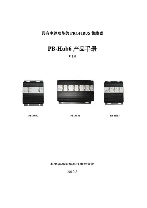
具有中继功能的PROFIBUS 集线器PB-Hub6产品手册V 1.0PB-Hub2PB-Hub6PB-Hub3北京鼎实创新科技有限公司2010-3目录第一章产品概述 (2)1. 产品系列 (2)2. PROFIBUS集线器技术概念 (2)2. PROFIBUS集线器PB-Hub6主要用途 (3)3. 产品特点 (4)4.技术指标 (5)第二章产品结构、安装、指示灯 (6)1.产品外形 (6)2. 外形尺寸 (6)3. 安装 (6)4.电源 (7)5.指示灯 (7)6.上电步骤及故障排除 (8)第一章 产品概述具有中继功能的PROFIBUS 集线器PB-Hub6(以下简称PROFIBUS 集线器或集线器),应用于PROFIBUS 现场总线网络中,可将网络的总线型拓扑结构改变为树型结构或混合型结构,同时保留了中继器的技术功能。
本装置以方便工程现场的安装布线、增加网络的传输距离和站点个数为目的, 同时还具有网络隔离和通信诊断功能。
1. 产品系列PROFIBUS 集线器PB-Hub6是北京鼎实创新科技公司网络部件系列中的产品。
网络部件系列产品型谱见下表1-1所示:表1-1 网络部件系列产品列表:型号品名网络协议技术指标其他网络协议¾ 6 PROFIBUS DP 接口¾波特率自适应0~12M PROFIBUS 集线器 其他标准 PB-Hub6PROFIBUS¾无主/从端口之分别RS485网络¾物理层转换,与上层协议无关PB-Hub3同上 PROFIBUS其他标准 ¾3 PROFIBUS DP 接口RS-485网络 ¾其余同上PB-Hub2 PROFIBUS 中继器 PROFIBUS其他标准¾2 PROFIBUS DP 接口 RS-485网络¾其余同上¾波特率:9.6K~12M ,拨码开关设置¾光纤类型:多模玻璃光纤,波长850nm 其他标准 PB-OLM02 PROFIBUS 光纤模块 PROFIBUS¾光纤通讯距离:2Km RS485网络¾光纤接口类型:4×ST 口 ¾光纤链路模式:总线型,星型¾2×9孔D 型 PB-DS50BPROFIBUS 插头 PROFIBUS其他标准¾终端电阻开关 RS485网络 ¾诊断指示灯 ¾2×9孔D 型 CO-CNCT-2CANopen 插头 CANopen其他标准¾终端电阻开关 CAN 网络¾诊断指示灯2. PROFIBUS 集线器技术概念PROFIBUS-DP 采用基于RS485技术的物理层,是目前应用最普遍的一种形式。

详细信息隔离型RS232/485到4路RS485集线器。
有效隔离从口RS485之间、从口RS485和主口RS485之间干扰。
RS485主口和从口支持256个从站,超强信号放大能力。
可实现RS485网络的中继、扩展与隔离。
可以作为有源、隔离型RS232转RS485转换器。
宽电压输入、支持导轨安装。
RS485接反指示,接反时指示灯常亮。
ZLAN9440/9410概述ZLAN9440是一款可通过一路RS485/232主口扩展出4路RS485从口的工业级隔离型4口RS485集线器。
可以有效的实现RS485网络的中继、扩展与隔离。
ZLAN9440同时可以作为有源的隔离型的RS232转RS485转换器。
如果只需要一路有源隔离型RS232转RS485则型号是ZLAN9410。
如需8口485HUB,请选择ZLAN9480A。
ZLAN9440的主口端同时提供隔离型RS485和RS232两种接口,从口端扩展出4路隔离型RS485接口。
一般RS485接线时要求手拉手接线方式,需要避免主站为中心的星型连接。
但是某些情况下为了方便,需要采用星型连接,此时采用RS485 HUB可以有效隔离多个RS485之间的连线干扰。
ZLAN9440有源隔离型RS485集线器产品是专门针对工业现场恶劣环境而设计的,对于那些要求高可靠性和安全性的场合尤其适合。
光电隔离功能可以有效的使RS485主从设备之间彼此隔离开来,避免因主从设备间的地电位差、以及静电、雷击和浪涌对RS485主从设备造成的损害,同时也有效的避免了主从设备端的地电位差而在设备间产生的地环流对RS485设备造成的损害。
ZLAN9440有4大应用方式:1. 隔离:有效隔离RS485网络的主从端;同时隔离4个从站。
2. 中继:可以有效延长RS485网络的通讯距离。
3. 扩展:可以实现1路RS485到4路RS485的扩展,成倍增加网络内RS485设备的数量。
4. 转换:还可以实现1路RS-232到4路RS485的转换。

四星电子PROFIBUS集线器FS-PBHUB-4FS-PBHUB-6用户手册德阳四星电子技术有限公司版权所有侵权必究目录前言 (3)版权声明 (3)版本信息 (3)产品包括 (3)一、PROFIBUS网络的基本特点 (4)二、PROFIBUS集线器的主要用途和特点 (5)三、产品特性及主要技术参数 (8)四、外部结构及管脚定义 (9)五、内部原理框图 (12)六、PROFIBUS集线器的应用方案 (13)七、常见问题解答 (15)八、订货信息 (17)前言感谢您使用德阳四星电子技术有限公司出品的系列现场总线网络产品。
使用前请务必仔细阅读此用户手册,你将领略其完善的功能和简洁的操作方法。
本用户手册将详细介绍四星电子的六口PROFIBUS集线器FS-PBHUB-6和四口集线器FS-PBHUB-4的使用方法,型号中的FS字符是德阳四星电子技术有限公司注册商标的缩写。
本产品主要用于PROFIBUS、MPI、PPI现场总线网络,可将网络的总线型拓扑结构改变为星型结构或混合型结构,同时也实现了中继器的技术功能。
本装置以方便工程现场的安装布线、增加网络的传输距离和站点数量为目的, 同时还具有网络隔离和信号指示诊断功能。
请用户按照用户手册中的技术规格和性能参数进行操作,本公司不承担由于用户操作不当造成的财产损失或人身伤害责任。
本公司有权在未经声明前根据技术发展的需要对本手册内容和产品功能进行更改。
版权声明本手册版权属于德阳四星电子技术有限公司所有,任何人和机构未经本公司书面同意进行全部或部分的内容复制将承担相应的法律责任。
版本信息文档名称:《四星电子PROFIBUS集线器用户手册》版本:V2.0修改日期:2011-05-13,2012-07-03,2013-06-03,2022-03-30产品包括1、FS-PBHUB-6 1台,或FS-PBHUB-4 1台。
FS-PBHUB-6为六口集线器,FS-PBHUB-4为四口集线器,其它功能完全相同。
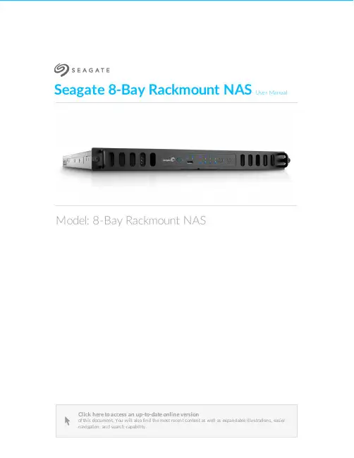
Seagate 8-Bay Rackmount NASUser ManualClick here to access an up-to-date online version of this document. You will also find the most recent content as well as expandable illustrations, easiernavigation, and search capability.Model: 8-Bay Rackmount NAS. . . . . . . . . . . . . . . . . . . . . . . . . . . . . . . . . . . . . . . . . . . . . . . . . . . . . . . . . . . . . . . . . . . . . . . . . . . . . . . . . . . . . . . .. . . . . . . . . . . . . . . . . . . . . . . . . . . . . . . . . . . . . . . . . . . . . . . . . . . . . . . . . . . . . . . . . . . . . . . . . . . . . . . . . . . . . . . . . . . . . . . . . . . . . . . . . . . . . . . . . . . . . . . . . . . . . . . . . . . . . . . . . . . . . . . . . . . . . . . . . . . . . . . . . . . . . . . . . . . . . . . . . . . . . . . . . . . . . . . . . . . . . . . . . . . . . . . . . . . . . . . . . . . . . . . . . . . . . . . . . . . . . . . . . . . . . . . . . . . . . . . . . . . . . . . . . . . . . . . . . . . . . . . . . . . . . . . . . . . . . . . . . . . . . . . . . . . . . . . . . . . . . . . . . . . . . . . . . . . . . . . . . . . . . . . . . . . . . . . . . . . . . . . . . . . . . . . . . . . . . . . . . . . . . . . . . . . . . . . . . . . . . . . . . . . . . . . . . . . . . . . . . . . . . . . . . . . . . . . . . . . . . . . . . . . . . . . . . . . . . . . . . . . . . . . . . . . . . . . . . . . . . . . . . . . . . . . . . . . . . . . . . . . . . . . . . . . . . . . . . . . . . . . . . . . . . . . . . . . . . . . . . . . . . . . . . . . . . . . . . . . . . . . . . . . . . . . . . . . . . . . . . . . . . . . . . . . . . . . . . . . . . . . . . . . . . . . . . . . . . . . . . . . . . . . . . . . . . . . . . . . . . . . . . . . . . . . . . . . . . . . . . . . . . . . . . . . . . . . . . . . . . . . . . . . . . . . . . . . . . . . . . . . . . . . . . . . . . . . . . . . . . . . . . . . . . . . . . . . . . . . . . . . . . . . . . . . . . . . . . . . . . . . . . . . . . . . . . . . . . . . . . . . . . . . . . . . . . . . . . . . . . . . . . . . . . . . . . . . . . . . . . . . . . . . . . . . . . . . . . . . . . . . . . . . . . . . . . .. . . . . . . . . . . . . . . . . . . . . . . . . . . . . . . . . . . . . . . . . . . . . . . . . . . . . . . . . . . . . . . . . . . . . . . . . . . . . . . . . . . . . . . . . . . . . . . . . . . . . . . . . . . . . . . . . . . . . . . . . .. . . . . . . . . . . . . . . . . . . . . . . . . . . . . . . . . . . . . . . . . . . . . . . . . . . . . . . . . . . . . . . . . . . . . . . . . . . . . . . . . . . . . . . . . . . . . . . . . . . . . . . . . . . . . . . . . . . . . . . . . .. . . . . . . . . . . . . . . . . . . . . . . . . . . . . . . . . . . . . . . . . . . . . . . . . . . . . . . . . . . . . . . . . . . . . . . . . . . . . . . . . . . . . . . . . . . . . . . . . . . . . . . . . . . . . . . . . . . . . . . . . .. . . . . . . . . . . . . . . . . . . . . . . . . . . . . . . . . . . . . . . . . . . . . . . . . . . . . . . . . . . . . . . . . . . . . . . . . . . . . . . . . . . . . . . . . . . . . . . . . . . . . . . . . . . . . . . . . . . . . . . . . . . . . . . . . . . . . . . . . . . . . . . . . . . . . . . . . . . . . . . . . . . . . . . . . . . . . . . . . . . . . . . . . . . . . . . . . . . . . . . . . . . . . . . . . . . . .Contents1Regulatory Compliance 2Introduction 3Safety Guidelines 4System Overview 5System LEDs 6Setting Up 7Operation 8Software 9Hardware Maintainance Precautions Front chassis Rear chassis Blinking purple LED: Confirm the connection 10Getting Help Troubleshooting topics . . . . . . . . . . . . . . . . . . . . . . . . . . . . . . . . . . . . . . . . . . . . . . . . . . . . . . . . . . . . . . . . . . . . . . . . . . . . . . . . . . . . . . . . . . . . . . . . . . . . . . . . . . . . . . . . . . Remove the front cover . . . . . . . . . . . . . . . . . . . . . . . . . . . . . . . . . . . . . . . . . . . . . . . . . . . . . . . . . . . . . . . . . . . . . . . . . . . . . . . . . . . . . . . . . . . . . . . . . . . . . . . . . . . . . . . . . . Front chassis information . . . . . . . . . . . . . . . . . . . . . . . . . . . . . . . . . . . . . . . . . . . . . . . . . . . . . . . . . . . . . . . . . . . . . . . . . . . . . . . . . . . . . . . . . . . . . . . . . . . . . . . . . . . . . . . . . . Replace a power supply unit (PSU). . . . . . . . . . . . . . . . . . . . . . . . . . . . . . . . . . . . . . . . . . . . . . . . . . . . . . . . . . . . . . . . . . . . . . . . . . . . . . . . . . . . . . . . . . . . . . . . . . . . . . . . . . . . . . . . . . Replace a hard drive . . . . . . . . . . . . . . . . . . . . . . . . . . . . . . . . . . . . . . . . . . . . . . . . . . . . . . . . . . . . . . . . . . . . . . . . . . . . . . . . . . . . . . . . . . . . . . . . . . . . . . . . . . . . . . . . . . Replace a fan . . . . . . . . . . . . . . . . . . . . . . . . . . . . . . . . . . . . . . . . . . . . . . . . . . . . . . . . . . . . . . . . . . . . . . . . . . . . . . . . . . . . . . . . . . . . . . . . . . . . . . . . . . . . . . . . . . Remove the rear cover . . . . . . . . . . . . . . . . . . . . . . . . . . . . . . . . . . . . . . . . . . . . . . . . . . . . . . . . . . . . . . . . . . . . . . . . . . . . . . . . . . . . . . . . . . . . . . . . . . . . . . . . . . . . . . . . . . Rear chassis information . . . . . . . . . . . . . . . . . . . . . . . . . . . . . . . . . . . . . . . . . . . . . . . . . . . . . . . . . . . . . . . . . . . . . . . . . . . . . . . . . . . . . . . . . . . . . . . . . . . . . . . . . . . . . . . . Installed components . . . . . . . . . . . . . . . . . . . . . . . . . . . . . . . . . . . . . . . . . . . . . . . . . . . . . . . . . . . . . . . . . . . . . . . . . . . . . . . . . . . . . . . . . . . . . . . . . . . . . . . . . . . . . . . . . . Replace the battery . . . . . . . . . . . . . . . . . . . . . . . . . . . . . . . . . . . . . . . . . . . . . . . . . . . . . . . . . . . . . . . . . . . . . . . . . . . . . . . . . . . . . . . . . . . . . . . . . . . . . . . . . . . . . . . . . . RAM . . . . . . . . . . . . . . . . . . . . . . . . . . . . . . . . . . . . . . . . . . . . . . . . . . . . . . . . . . . . . . . . . . . . . . . . . . . . . . . . . . . . . . . . . . . . . . . . . . . . . . . . . . . . . . . . Adding a DIMM (RAM) to an empty slot . . . . . . . . . . . . . . . . . . . . . . . . . . . . . . . . . . . . . . . . . . . . . . . . . . . . . . . . . . . . . . . . . . . . . . . . . . . . . . . . . . . . . . . . . . . . . . . . . . . . . . . . . . . . . . . . Remove a DIMM (RAM). . . . . . . . . . . . . . . . . . . . . . . . . . . . . . . . . . . . . . . . . . . . . . . . . . . . . . . . . . . . . . . . . . . . . . . . . . . . . . . . . . . . . . . . . . . . . . . . . . . . . . . . . . . . . . . . . . The 8-bay Rackmount NAS will not turn on.. . . . . . . . . . . . . . . . . . . . . . . . . . . . . . . . . . . . . . . . . . . . . . . . . . . . . . . . . . . . . . . . . . . . . . . . . . . . . . . . . . . . . . . . . . . . . . . . . . . . . . . . . . . . . . . . . . The 8-bay Rackmount NAS turns off when I connect a USB device.4567891011121212121416172224242527273030333436363637Regulatory ComplianceIntroduc onSafety GuidelinesSystem OverviewSystem LEDsSe ng UpOpera onSo wareHardware MaintainanceThe 8-bay Rackmount NAS has a front and rear chassis, each with its own cover. Review the details below for hardware module locations and, where applicable, replacement.Precau onsHot-swapping means that you can perform maintenance or upgrade hardware while the NAS is powered on. The 8-bay Rackmount NAS features three hot-swappable parts: hard drives; fans; and power supply units.Prior to performing hardware maintenance on other parts of the NAS (such as RAM and the battery),power off the product and disconnect the power from the power supply. Use NAS OS or a short push on the power button to shut down the NAS before unplugging the power cables.During operation, all provided hardware (including the installed drives in their frames) should remain in place for optimal air flow. Users with less than eight disks are not required to install empty disk trays in the enclosure. Airflow and fan performance are regulated by temperature.Observe all conventional ESD precautions when handling 8-bay Rackmount NAS parts. Avoid contact with backplane components and module connectors, etc.In most instances, the top cover should be removed only when the unit has been turned off and allowed to cool down. Potential hazards of opening the cover while the product is operating includes, but is not limited to, hot surfaces and exposed parts.Front chassisRemove the front cover1. Power down the NAS using NAS OS and unplug the power supplies. Wait for the components to completely cool before moving to Step2.2. Slide the NAS toward you until it locks into position.Refer to the product'sWarranty before performing any hardware repairs or maintenance that is not described in this manual.3. Release the cover by simultaneously pushing both front latches toward you.4. Lift the cover and remove it from the NAS.Front chassis informa on1. Fans (x3)2. Frame 1, hard drives 1 - 43. Hard drive LEDs; SATA connections4. Frame 2, hard drives 5 - 8Replace a power supply unit (PSU)For optimal power management, the power load for the NAS is shared between the two PSU. If one should fail, all power will automatically run from the active PSU, guaranteeing continuous NAS operation. To help extend the lifetime of your hardware, make certain to replace a failed PSU as soon as possible. Follow the instructions below to replace a PSU:1. Locate the PSU on the rear of the NAS.2. Unlock the PSU by pushing its latch toward the handle.3. Remove the PSU by pulling the handle away from the NAS.4. Insert the replacement PSU into the empty PSU slot.Replace a hard driveIf a failed hard drive is under warranty, make certain to contact Seagate customer support to receive a replacement disk.When adding or replacing hard drives, consider using Seagate hard drives that are optimized for use with your 8-bay Rackmount NAS. See Seagate Enterprise Drives for further information.1. Power down the system, unplug the power supply, and remove the cover as described above.2. Push the disk’s lock button to open the latch.Important info:Replace a faulty drive with a drive of equal or greater capacity.When handling drives, make sure that they are placed (and stored) on a cushioned surface. Important info:When following the instructions below, make certain to place the new or replacement disk on the drive guides before connecting the ends to the SATA ports. Attachingthe drive to the SATA ports before placing it on the guides will damage the SATA connections.3. Place the disk on the NAS’s hard drive guides. Confirm that the disk is correctly aligned on the guides bygently pushing it away from the SATA connection.4. Slide the disk into the SATA connection.5. Close the disk’s latch.6. Repeat the steps for each disk.7. Replace the cover and slide the NAS into the rack. To unlock the rails, pull the rail fasteners on each sidetoward you. Secure the NAS to the rack using the two front screws.8. Log on to the Seagate 8-bay Rackmount NAS from a workstation on your network to manage the newstorage.9. Rebuild the NAS volume. For details, refer to Software.Replace a fanCaution: The fans are hot-swappable and can be replaced when the NAS is powered on. Youmust use caution when removing a fan. In most instances, the fan will stop rotating once it isremoved from its slot. However, moving parts can cause severe damage to your hands andbody.1. Remove the cover as described above.2.Using your forefinger and thumb, pinch the clips that secure the fan to its slot.3. Lift the fan from its slot. Show caution when removing the fan since moving parts can cause severe damage. The fan should stop rotating once it is removed from its slot.Important info:The NAS is temperature controlled via an internal sensor. When removing one of the three fans, the other two will turn faster to maintain the required operational temperature.The faster rotation will be sudden and can become loud. If your NAS fans appear to be louderthan normal, confirm that the room's temperature is within operational range (see SafetyGuidelines ).4. Insert the replacement fan into the empty slot.Rear chassisRemove the rear cover1. Power off, unplug the power supplies, then wait for the components to completely cool.2. Slide the NAS toward you until it locks into position.3. Remove the two screws on the rear cover.4. Slide the cover toward the rack and remove it from the NAS.Rear chassis informa on1. PCIe slots2. Battery3. Central Processing Unit (CPU)4. RAM slots5. Power supplies (x2) Installed componentsInstalled componentsThe rear chassis is shipped with the following:1. PCIe: SATA extender (do not remove the SATA extender or add third-party PCIe boards to the NAS)2. Battery: 3V Lithium Battery (CR2032)3. CPU: Intel® Ivy Bridge 2.3GHz4. RAM: 4GB DDR3 DIMM ECC (x1)5. Power supplies: 100 to 240 VAC, 50 to 60 Hz (x2)Replace the ba eryThe battery is located next to the PCIe slots and protected by the extension card support. To remove the extension card support, you will need a Torx screwdriver with a T6 point.Use caution when replacing the battery. There is a strong risk of explosion if the battery is replaced by an incorrect type.1. Power off the system, unplug the power supply, and remove the rear cover as described above.2. Remove the screws from the extension card support.3. Gently unfasten the extension card support from the extension card and remove it to provide access tothe battery.4. Use one hand to press the battery's retaining clip away from the batter and use the other hand to lift thebattery from its socket.5. Insert the replacement battery into the battery socket.6. Connect the extension card support to the extension card and fasten its screws.7. Replace the rear cover and connect the power supply cables.8. Power on the NAS.Make certain to dispose of used batteries according to the applicable laws for your region.RAMAdding a DIMM (RAM) to an empty slot1. Power off the NAS, unplug the power supply, and remove the cover as described above.2. Locate an empty DIMM slot and press its retaining clips outward.3. Align the DIMM on the slot's socket. Make certain that the edge of the DIMM's notch matches the key forthe socket.4. Hold the DIMM on both ends and carefully insert it into the socket. The DIMM is properly inserted whenyou cannot push it further and the retaining clips snap into place.Important info: Always insert the DIMM vertically to avoid damaging the notch. You may have toapply a limited amount of force on the DIMM's edges when pushing it into the socket.Remove a DIMM (RAM)1. Power off the NAS, unplug the power supply, and remove the cover as described above.2. Press the retaining clips outward to unlock the DIMM from its socket.3. Hold the DIMM on its two ends and lift it from the socket.Blinking purple LED: Confirm the connec onA blinking purple LED indicates that the backplane and motherboard cannot communicate. Follow the steps below to determine if the cable is properly seated:1. Power off the 8-bay Rackmount NAS.2. Remove the rear cover.3. Confirm that the communication cable between the backplane and motherboard is firmly connected. Thecable is located directly in front of the PCIe SATA Extender.4. If the connection is loose, try to fix it into place.5. Install the rear cover.6. Power on the 8-bay Rackmount NAS.If the LED continues to blink purple, contact Seagate support.Ge ng HelpIf you are having issues with your product, first consult this user manual and the troubleshooting topics below. If the problem persists, refer to:The Seagate NAS OS User Manual Seagate Technical SupportWarranty rights and responsibilitiesT roubleshoo ng topicsThe 8-bay Rackmount NAS will not turn on.Q: Can you confirm that the NAS is receiving power?A: Make sure the power cord is properly connected, then push the power button until the Status LED turns ON.Q: Have you connected a USB storage device?A: The NAS may be attempting to boot from it. Unplug the device and retry to reboot the system.Q: Does the motherboard battery need to be replaced?A: A non-functioning motherboard battery could prevent the system from booting. Contact Seagate support for confirmation and help.Q: Is there a problem with one or both power supply units?A: Connect a monitor, mouse, and keyboard, and turn your product on. If you don't see anything on themonitor,that means that the problem may result from the NAS's power supply units. Your NAS has redundant power supplies that allow for one to fail. Contact Seagate support if you believe that one or both power supplies have failed. In the rare case in which both power supplies fail at the same time, you may be asked to send NAS to Seagate for review.Note:Seagate is dedicated to providing high quality products that enrich the lives of our customers. To help Seagate offer the best customer support, we encourage you to create anaccount and register your product at Seagate Product Registration . You can give us importantfeedback as well as receive updated information on your Seagate device.______________________________________________________________________________________The 8-bay Rackmount NAS turns off when I connect a USB device. Q: Have you connected more than three bus-powered USB devices or is one of your devices drawing an inordinate amount of power?A: Connect no more than three bus-powered USB devices and/or make sure that none of the devices is drawing an inordinate amount of power.Q: Did the product turn off as soon as the USB device and the 8-bay Rackmount NAS's USB port came into contact?A: The USB device may have caused a short circuit. Unplug any USB devices you have connected since the failure and reboot the product.。
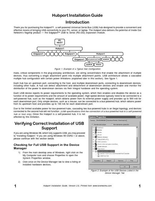
Hubport Installation GuideIntroductionThank you for purchasing the Hubport ™, a self-powered Universal Serial Bus (USB) hub designed to provide a convenient and effective means of bringing USB connectivity to your PC, server, or laptop. The Hubport also delivers the potential of Inside Out Network’s flagship product — the Edgeport ™ USB to Serial (RS-232) expansion module.Hubs, critical components in the plug-and-play architecture, are wiring concentrators that enable the attachment of multiple devices, thus converting a single attachment point into multiple attachment points. USB architecture allows a cascaded multiple hub configuration with certain power limitations (explained later in this section). See figure 1.Each hub has an upstream port, connecting to the host, and multiple downstream ports, connecting to downstream devices,including other hubs. A hub can detect attachment and detachment of downstream devices and enable and monitor the distribution of the power to downstream devices via their integral hardware and the operating system.Each USB device reports its power requirements to the operating system, which then enables and disables the device as a function of its power requirements and the amount of available power. High-speed devices typically need to be connected to a self-powered hub, such as the Hubport, which obtains power from its external power supply and provides up to 500 mA for each downstream port. Only simple devices, such as a mouse, can be connected to a bus-powered hub, which obtains power from its upstream host and provides up to 100 mA for each downstream port.Due to the limited available power for bus-powered hubs, cascading two bus-powered hubs is an illegal topology, and devices connected to the second hub will not function. (USB specifications limit the connection of a bus-powered hub to a self-powered hub or host only.) Since the Hubport is a self-powered hub, it is not affected by this limitation.Verifying Correct Installation of USBSupportIf you are using Windows 98, which fully supports USB, you may proceed to “Installing Hubport.” If you are using Windows 95 OSR2.1 or above,please continue with the section below.Checking for Full USB Support in the Device Manager1)From the main desktop area of Windows, right click on the My Computer icon and choose Properties to open the System Properties window.2)Click once on the Device Manager tab to view a listing of installed hardware devices.Figure 1: Example of a Typical Hub ConfigurationPCHOST HubportHubportEdgeportEdgeportEdgeportscannerbus-powered hubjoystick mouseFigure 2: Example of the USB Devices Listed in theDevice Manager Tab3)In the Device Manager tab, your hardware devices are in alphabetical order and should include a Universal serialbus controller toward the bottom of the list. Double click on this device to open it.In order for the Hubport and other USB devices to work properly at least two devices are required and will be listed. Although the exact name of each manufacturer’s device listing can vary, the names of these two required USB devices should include the following descriptive words:•USB Root Hub•USB Host ControllerFigure 2 shows an example of what you might see listed under the Universal serial bus controller. If you do not see one or both of these devices, go to “Determining Why Support Is Not Present.”Installing HubportPlugging Hubport Into Your PCPlug in the power supply. Plug the flat end of the UBS cable into the downstream A connector located in the back of your computer or USB hub port. Plug the D-shaped end into the Hubport.If previously installed, the Hubport will be listed in the System Device Manager and is ready for immediate use. With the initial installation, the Update Device Driver Wizard automatically appears and you may continue with “Installing the Drivers” below. If the Update Device Driver Wizard does not appear, go to the preceeding section, “Verifying Correct Installation of USB Support.”Installing the DriversTo install your Hubport drivers:1Click on NEXT to initiate a search for the updated driver device.2)Click on FINISH to continue with the installation.You have now successfully installed your Hubport!Determining Why Support Is Not PresentTo verify that the necessary hardware, a USB Host Controller, is installed in your system, make sure that your PC has USB connectors. If not, then this system will not support USB regardless of the Windows version. You will need to purchase a PCI USB controller card, such as the Step Up Kit™ from Inside Out Networks. If your PC has USB connectors, verify that the USB hardware is enabled in your system BIOS configuration.In some cases your manufacturer may have elected to ship your PC without the USB support drivers installed. If the two USB device manager hardware listings are absent in your Device Manager, proceed to the next section, “Installing Microsoft USB Support.”After installing USB Support from your Microsoft Windows 95 OEM system disk, check your Device Manager again. If the two devices are not present or Windows Plug & Play does not auto detect the Hubport, try the following:1)If only the HOST Controller is listed in the Device Manager then remove it and reboot.2)From the Control Panel, open the System Properties and select “Check for a device labeled ?UNKNOWN.” IfROOT HUB and HOST Controller are listed, then remove them and reboot.If, after rebooting, the Add Hardware Wizard finds the USB devices and requires new drivers, such as UHCD.SYS, you can locate the drivers in the C:\WINDOWS\SYSTEM directory. If, after following the proceedures decribed in this guide, you still cannot install you Hubport, please call (512)301-7080 and ask for Technical Support.Installing Microsoft USB SupportMicrosoft provides a supplemental program (usbsupp.exe) to allow users to upgrade Windows 95 version OSR2 to support the Universal Serial Bus. In order to install this support perform the following steps:1)Insert your Microsoft Windows 95 OEM system disk into your CD drive.2)In the START menu, select RUN.3)Type <CD drive letter>:\other\usb\usbsupp.Follow the instructions on the screen.After rebooting, continue with the “Installing Hubport” section.Note that Windows 95 version 4.0.950 and 4.0.950a do not support the upgrade path to USB. Unfortunately, Microsoft has not provided an upgrade path to OSR2 from earlier versions of Windows. OSR2 must be preinstalled by your PC vendor. Contact your PC vendor for more information.Copyright © 1998 by Inside Out Networks. All rights reserved.Version 2.0 November 1998Hubport, Edgeport, and Step-Up Kit are trademarks of Inside Out Networks. All other products are trademarks or registered trademarks of their respective owners. Information in this documentation is subject to change without notice and does not represent a commitment on the part of Inside Out Networks Inc.Inside Out Networks provides this document “as is,” without warranty of any kind, either expressed or implied, including, but not limited to, the particular purpose. Inside Out Networks may make improvements and/or changes to this documentation or to the product(s) and/or program(s) described in this documentation at any time.Inside Out Networks assumes no responsibility of any errors, technical inaccuracies, or typographical errors that may appear in this documentation, nor liability for any damages arising out of its use. Changes are made periodically to the information herein; these changes may be incorporated in new editions of the publication.For U.S. Government use:Any provision of this document and associated computer programs to the U.S. Government is with “Restricted Rights.” Use, duplication, or disclosure by the gov-ernment is subject to the restrictions set forth in, subparagraph (c) (1) (ii) of the Rights in Technical Data and Computer Software clause of DFARS 52.277-7013.For non-U.S. Government use:These programs are supplied under a license. They may be used, disclosed, and/ or copied only as supplied under such license agreement. Any copy must contain the above copyright notice and restricted rights notice. Use, copying, and/or disclosure of the programs is strictly prohibited unless otherwise provided for in the license agreement.Federal Communications Commission (FCC)Regulatory Information (USA only)This equipment has been tested and found to comply with the limits for a Class B digital device, pursuant to Part 15 of the FCC Rules. These limits are designed to provide reasonable protection against harmful interference in a residential installa-tion. This equipment generates, uses, and can radiate radio frequency energy and, if not installed and used in accordance with the instructions, may cause harmful inter-ference to radio communications. However, there is no guarantee that interference will not occur in a particular installation. If this equipment does cause harmful inter-ference to radio or television reception, which can be determined by turning the equipment off and on, the user is encouraged to correct the interference by one or more of the following measures:±Reorient or relocate the receiving antenna.±Increase the separation between the equipment and the receiver.±Connect the equipment into an outlet that is on a circuit different from the receiver.±Consult the dealer or an experienced radio/TV technician for help.Warning: The connection of a non-shielded interface cable to this equipment will invalidate the FCC Certification for this device.Department of Communication (DOC) Notice(Canada only)This Class B digital apparatus meets the requirements of the Canadian Interfer-ence-Causing Equipment Regulations.Cet appareil numérique de la Classe B respecte toutes les exigences du Règlement sur le matériel brouiller du Canada.Declaration of Conformity (DOC)according to ISO/IEC Guide 22 and EN 45014Manufacturer’s Name:Inside Out NetworksManufacturer’s Address:8313 Highway 71 West, Suite BAustin, Texas 78735 USAdeclares that the productProduct Name:Hubport/7, Hubport/4Model Number(s):301-1010-07, 301-1010-04, 301-1011-04Product Options:Allconforms to the following Product Specifications:Safety:IEC 950:1991 +A1, A2, A3/EN 60950:1992 + A1, A2, A3UL 1950, 3rd edition, CSA No. 950EMC:FCC Title 47 CFR, Part 15 Class BFCC/CISPR 22/85 Class B (ANSI C63.4 1992)EN 55022 Class B (1994 w/A1 1995)EN 50082-1:1992 - Generic ImmunityIEC 801-2:1991/prEN 55024-2:1992 - kV CD, 8 kV ADIEC 801-3:1994/prEN 55024-3:1991 - 3V/mIEC 801-4:1988/prEN 55024-4:1992 - 0.5 kV Signal Lines,1 kV Power LinesSupplementary InformationThe Product herewith complies with the requirements of the following Direc-tives and carries the CE marking accordingly.±the EMC Directive 89/336/EEC (including 93/68/EEC)±the Low V oltage Directive 73/23/EEC (including 93/68/EEC)This device complies with Part 15 of the FCC Rules. Operation is subject to the following two conditions: (1) this device may not cause harmful interference, and (2) this device must accept any interference received, including interference that may cause undesired operation.Quality ManagerAustin, Texas April, 1998To Contact Inside Out Networks...Our Web Page is located at , where you may download drivers and get current product information.For more information on Inside Out Networks’ products, you may contact us by E-Mail at ******************* or at the address and telephone number below. For sales, you may contact us by E-mail at ********************.For technical support, you may contact us at (512) 301-7080.Inside Out Networks, 8313 Hwy. 71 West, Suite B, Austin, TX 78735 ph: (512) 301-7080 fax: (512) 301-7060。
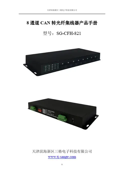
8通道CAN转光纤集线器产品手册型号:SG-CFH-821天津滨海新区三格电子科技有限公司一、概述1.1产品用途SG-CFH-821可以实现将8路消防主机的CAN信号通过光纤汇总到一台总控室消防主机上,实现消防主机间的光纤通信。
该产品具有级联扩展功能,可实现三级级联。
产品使用方便,配置简单。
1.2产品特点凡具有CAN接口的各类设备都可以通过本产品实现光纤的互联互通。
如:具有CAN接口的消防主机及各类传感器等都可以使用该产品进行互联通信。
1.3技术指标1)电源电压:12~24V宽电压供电。
2)额定功率7.2W(24V/300mA)。
3)8路光纤接口,单模、SC口(可选择其他接口,LC FC等)、单双纤可选,波长1310nm。
4)两路协议型CAN接口,支持CAN2.0A和CAN2.0B协议,符合ISO/DIS 11898规范;用于连接主机及扩展级联使用。
5)环境温度:运输和存储:-40℃~+70℃。
工作温度:-20℃~+60℃。
6)工作相对湿度:5~95%(无结露)。
7)外形尺寸:(长)330mm×(宽)134mm×(厚)34mm。
8)安装方式:机架安装。
9)防护等级:IP20。
10)重量:约300g。
二、安装及使用2.1接口说明2.1.1电源接口产品电源接口采用两种形式,5.08压线端子排和DC2.1接线插头方式,用户可根据具体需求自行选择接线方式。
接线端子排线序如下:2.1.2CAN 接口EL 和EH 为集线器级联CAN 接口,可连接下一台CAN 集线器的ML 和MH 。
ML 和MH 连接总控室消防主机的CANL 和CANH 。
符号定义V+电源正极,12-24VDCG 电源负极〨外部大地接线DC2.1电源头接线端口2.1.3指示灯状态各指示灯状态如下表所示:符号定义状态说明Pow 电源指示灯熄灭电源未接通常亮电源接通Err CAN 错误指示灯熄灭没有CAN 错误常亮CAN 通道通信错误CM 主机CAN 指示熄灭CAN 总线未接收数据常亮CAN 总线在接收数据CE 扩展CAN 指示熄灭CAN 总线未接收数据常亮CAN 总线在接收数据CS1光纤1数据指示灯熄灭没有数据收发常亮有数据收发功能符号定义CAN 级联扩展接口EL 级联CAN 总线低EH 级联CAN 总线高主机CAN 接口ML 消防主机CAN 总线高MH 消防主机CAN 总线低接地G接地CS2光纤2数据指示灯熄灭没有数据收发常亮有数据收发CS3光纤3数据指示灯熄灭没有数据收发常亮有数据收发CS4光纤4数据指示灯熄灭没有数据收发常亮有数据收发CS5光纤5数据指示灯熄灭没有数据收发常亮有数据收发CS6光纤6数据指示灯熄灭没有数据收发常亮有数据收发CS7光纤7数据指示灯熄灭没有数据收发常亮有数据收发CS8光纤8数据指示灯熄灭没有数据收发常亮有数据收发F1光纤1连接指示灯熄灭光纤没有连接上常亮光纤正常连接F2光纤2连接指示灯熄灭光纤没有连接上常亮光纤正常连接F3光纤3连接指示灯熄灭光纤没有连接上常亮光纤正常连接F4光纤4连接指示灯熄灭光纤没有连接上常亮光纤正常连接F5光纤5连接指示灯熄灭光纤没有连接上常亮光纤正常连接F6光纤6连接指示灯熄灭光纤没有连接上常亮光纤正常连接F7光纤7连接指示灯熄灭光纤没有连接上常亮光纤正常连接F8光纤8连接指示灯熄灭光纤没有连接上常亮光纤正常连接2.1.4CAN 波特率配置CAN 波特率配置采用拨码开关方式配置,拨码开关如下所示:把拨码开关第1位打开ON,即根据拨码开关进行速率配置。
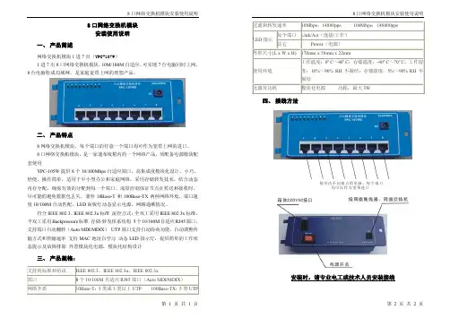
8口网络交换机模块安装使用说明 第 1 页 共 1 页8口网络交换机模块 安装使用说明一、 产品简述网络交换机模块1进7出(YPC-107W )1进7出8口网络交换机模块,10M/100M 自适应、可实现7台电脑同时上网,8台电脑组成局域网,是家庭宽带上网的理想产品。
二、 产品特点8网络交换机模块,每个端口的任意一个端口均可作为宽带上网的进口。
8口网络交换机模块,是一家通布线箱内的一个网络产品,须配备电源模块配套使用YPC-105W 提供8个10/100Mbps 自适应端口,高集成度模块化设计,小巧、轻便,操作简单,适用于中小型办公和家庭网络。
采用存储转发技术,结合动态内存分配,确保有效的分配到每一个端口。
流量控制保证节点在传送和接收时,尽可能的避免数据包丢失。
兼容10Base-T 和100Base-TX 两种网络环境,端口速度10/100M 自动匹配。
LED 面板灯动态显示电源、网路通断情况。
符合IEEE 802.3、IEEE 802.3u 标准 流控方式:全双工采用IEEE 802.3x 标准,半双工采用Backpressure 标准 存储-转发体系结构 5个10/100M 自适应RJ45端口,支持端口自动翻转(Auto MDI/MDIX ) UTP 端口支持自动协商功能,自动调整传输方式和传输速率 支持MAC 地址自学习 动态LED 指示灯,提供简单的工作状态提示及故障排除 外置模块化电源,模块化结构设计三、 产品规格:支持的标准和协议 IEEE 802.3、IEEE 802.3u 、IEEE 802.3x端口 8个10/100M 自适应RJ45端口(Auto MDI/MDIX ) 网络介质10Base-T :3类或3类以上UTP 100Base-TX :5类UTP8口网络交换机模块安装使用说明 第 2 页 共 2 页过滤和转发速率10Mbps:14880pps100Mbps:148800pps每个端口 Link/Act (连接/工作) LED 指示其它Power (电源)外形尺寸(L x W x H) 170mm x 58mm x 22mm使用环境工作温度:0ºC ~40ºC ;存储温度:-40ºC ~70ºC ,工作湿度:10%~90% RH 不凝结;存储湿度:5%~90% RH 不凝结电源及功耗模块化电源 功耗:最大3W四、 接线方法接室内不同地点的电脑。

Sales and Technical Support 1-800-225-7724The use of Ethernet in manufacturing operations offers nu-merous advantages including enhanced information flow with the enterprise system, ease of maintainability and simplified access to the Internet for use in remote monitoring and diag-nostics. The challenge in achieving these benefits on the factory floor is designing a network that will stand up to condi-tions much harsher than the office environment for which most Ethernet components were designed.The ENHSA is an 8 port switch that overcomes this hurdle and provides the user with a great deal of network design flexibility. The rugged construction enables the device to mounted anywhere in the factory (side of the machine, build-ing pillar, rafters, etc.) When mated with an RJ-Lnxx cordset, the ENHSA provides a sealed, IEC IP67 rated connection, that prevents ingress from common factory contaminants such as dirt, oil and water.While this manual explains the basic functionality of the unit, no programming is required to get the unit up and running. The ENHSA should function upon making the power and network connection as described within. Should you encoun-ter a problem with operation of your unit, please contact our technical support staff at 1-800-225-7724.Machine Mount IndustrialEthernet Active SwitchENHSAURR812RJ-Lnxx Machine Mount Industrial Ethernet Switch - Users ManualSection 1General Information Page 4Section 2LED Indicators Page 5Section 3Installation Page 6Section 4Switching Features Page 7 - 8Section 5Expanding the NetworkPage 9Conditions/WarrantyAll products sold by Woodhead L.P. are manufactured to be free from defects in material and workmanship for twelve (12) months from the date of delivery, provided there has been normal use. Should any defect in material or workmanship occur during the above time period in any part of the product as determined by Woodhead L.P.’s inspection of the defective part, Woodhead L.P. agrees, in its discretion, either to replace (not including installation) or repair the defective product free of charge and to deliver said part F.O.B. Woodhead L.P’s place of business; provided however, the buyer (i) gives prompt notice of the defect to Woodhead L.P., (ii) establishes its normal use and service of the product, and (iii) returns such defective part to Woodhead L.P. at the Buyer’s own expense. The aforementioned warranty extends only to the original purchaser of the product. WOODHEAD L.P. EXPRESSLY DISCLAIMS ANY AND ALL OTHER WARRANTIES OF ANY KIND WHATSOEVER AS TO THE PRODUCTS, INCLUDING, BUT NOT LIMITED TO, EXPRESS OR IMPLIED WARRANTIES AS TO MERCHANTABILITY, FITNESS FOR PURPOSE SOLD, AND DESCRIPTION OR QUALITY OF THE PRODUCTS.Any specifications described herein, or in any Woodhead L.P. written proposals, are only estimates and not intended as an express warranty. Any samples submitted by Woodhead L.P. to Buyer, any descriptions, illustrations or forecasts in trade literature, brochures or other documentation shall not be constructed as warranties as to substance, performance, or illustra-tions shall not constitute any breach of these terms or conditions by Woodhead L.P. .In no such event shall Woodhead L.P. be liable for any damages, ordinary, incidental, or consequential, including damages for loss of production, loss of anticipated profits or savings, or for any claims asserted against Buyer by a third party arising directly or indirectly from out of or in connection with the manufacture, sale, use or defect of the products. Woodhead L.P. shall in no event be liable for any physical injuries or death arising directly or indirectly from out of or in connection with the manufacture, sale, use or defect of the products. Buyer’s sole remedy shall be the terms of the warranty set forth above.Not withstanding anything to the contrary, where any product is delivered to Buyer that does not comply with the agreed terms between Buyer and Woodhead L.P. , or in any event of any loss or damage howsoever arising out of the products, the aggregate liability to Woodhead L.P. to Buyer shall be limited to and shall not exceed a sum which equals the price upon which such liability is based.INSTALLATION AND HAZARDOUS AREA WARNINGS:All power, input and output (I/O) wiring must be in accordance with Class I, Division 2 wiring methods and in accordance with the authority having jurisdiction.WARNING (EXPLOSION HAZARD) -SUBSTITUTION OF COMPONENTS MAY IMPAIR SUITABILITY FORCLASS 1, DIVISION 2.WARNING (EXPLOSION HAZARD) -WHEN IN HAZARDOUS LOCATIONS, DISCONNECT POWER BEFOREREPLACING OR WIRING UNITS.WARNING (EXPLOSION HAZARD) -DO NOT DISCONNECT EQUIPMENT UNLESS POWER HAS BEENSWITCHED OFF OR THE AREA IS KNOWN TO BE NONHAZARDOUS.FCC Statement:This equipment has been tested and found to comply with the limits for a Class A digital device, pursuant to Part 15 of the FCC Rules. These limits are designed to provide reasonable protection against harmful interference when the equipment is operated in a commercial environment. This equipment generates, uses, and can radiate radio frequency energy and, if not installed and used in accordance with the instruction manual, may cause harmful interference to radio communications. Operation of this equipment in a residential area is likely to cause harmful interference in which case the user will be required to correct the interference at his own expense.Copyright & Trademarks:Copyright WOODHEAD CONNECTIVITY, All Rights Reserved. RJ-Lnxx is a registered trademark of WOODHEAD CONNECTIV-ITY.Note: All information in this document is subject to change without notice.Sales and Technical Support 1-800-225-772434RJ-Lnxx Machine Mount Industrial Ethernet Switch - Users ManualThis manual will help you install and maintain the RJ-Lnxx ENHSAURR8 Industrial Ethernet Switch.This unmanaged switch is extremely easy to install and operate because no user configuration is required. Once the Ethernet connections are made and the unit is powered up it will immediately begin to operate.The vast majority of Ethernet networks are configured in a star topology, requiring Hub devices to direct messages between the stations on the network. While this can be accomplishedwith a Repeater Hub which receives a message then broadcasts it out all ports, this is an inefficient use of bandwidth. Additionally, all stations connected via a Repeater Hub share a collision domain ,meaning only one station can transmit at any one time. The ENHSAURR8 is an active switch, which unlike a Repeater Hub will intelligently route Ethernet messages only out the appropriate port. This switch is also a store and forward device, enabling multiple stations to communicate with the switch simultaneously. In factory automation environments, this function is essential for transmission of time critical information in a deterministic fashion.The RJ-Lnxx Industrial Ethernet Switch supports both 10BaseT (10 Mbps) and 100BaseTx (100 Mbps).Each port will independently auto-sense the speed allowing you to interface to regular or fast Ethernet devices.These general specifications apply to the ENHSAURR8. Refer to the separate data sheet or the WOODHEAD CONNECTIVITY Network Products Catalog for complete specifications.PortsEight 10/100BaseT(x), Shielded RJ45Required Power10 - 30 VDC, 1.9 Watt typical (80 mA @ 24 VDC) Mini Connector Ethernet StandardsIEEE 802.3 (10BaseT), 802.3u (100BaseTX), 802.3x (Full Duplex)Ethernet ProtocolsAll standard IEEE 802.3 protocols supported Speed Per Port10 or 100 Mbps (half duplex), 20 or 200 Mbps (full duplex)Ethernet Isolation1200 V olts RMS (for 1 minute)Operating Temp.-40 to 80 °C Humidity5 to 95% (non-condensing)IP Rating IEC IP67The RJ-Lnxx Industrial Ethernet Switch meets the following standards.Electrical safety - UL 508, CSA C22/14; EN61010-(IE1010) (PENDING)EMI emissions - FCC part 15, ICES 003 Class A; EN55022 (PENDING)EMC immunity - EN50082-1(IEC801-2,3,4) (PENDING)Hazardous locations – UL 1604, CSA C22.2/213 (Class 1, Div. 2), Groups A, B, C, D;Cenelec EN50021 (Zone 2)(PENDING)Section 1 General Information5Sales and Technical Support 1-800-225-7724The RJ-Lnxx Industrial Ethernet Switch has communication LEDs for each port and a power LED.Refer to the picture below for the location of these LEDs.Activity/Link Indicator Power IndicatorThis LED will be on solid when proper power has been applied to the unit.The activity (ACT) and link (LNK) indication is combined into one LED on the RJ-Lnxx Industrial Ethernet Switch. There is one of these LEDs per port.OFF – This would indicate that there is not a proper Ethernet connection (Link) between the port and another Ethernet device. Make sure the proper cable is in use and that it has been plugged securely into the ports at both ends. See section 5 for proper Ethernet cabling.ON Solid (not flashing) – This would indicate that there is a proper Ethernet connection (Link) between the port and another Ethernet device, but no communications activity is detected.Flashing - This would indicate that there is a proper Ethernet connection (Link) between the port and another Ethernet device, and that there is communications activity.This LED indicates what speed of communications is detected on the port. There is one ofthese LEDs per port.OFF – A 10 Mbp Power LED s (10BaseT) connection is detected.ON – A 100 Mbps (100BaseTx) connection is detected.(Mbps = Megabits per Second)Section 2 LED Indicators6RJ-Lnxx Machine Mount Industrial Ethernet Switch - Users ManualThe ENHSAURR8 is designed to mount in harsh environments without the need for a separate enclosure. Screws holes are located on each of the 4 corners of the switch,enabling a number 8 screw to be used to attach the switch to the side of a machine or any other solid e the diagram below as a template for drilling and tapping the mounting screw holes.The switch may be placed in the orientation that best suits the incoming Power andEthernet cables.The ENHSAURR8 is powered by 10 - 30 VDC, and is designed to be brought in via a sealed 4 pole mini connector. As shown below, pins 2 and 3 are used as the DC negative and DC positive input, respectively.The individual jacks within the switch are shielded, as are most versions of RJ-Lnxx cordsets. Each Ethernet channel should be brought to ground only at one point. Pin 4serves as a common connection point to take the individual Ethernet cable shields to ground. If the shields of any the cables have been brought to ground at another point,Pin 4 should not be connected in order to avoid possible ground loops.4321 1. Not Used 2. V-3. V+4. Ground For Cable Shields10.1”256.5mm 2.96”75.2mm 0.1930.39”9.9mm10BaseT and 100BaseTxEthernet (100BaseTx) has a maximum speed of 100 Mbps. The RJ-Lnxx Industrial Ethernet Switchautomatically supports both types.1.4Gbps combined bandwidthWith full duplex and 100BaseTx communications, each port can provide a full 200 Mbps of datathroughput.1K MAC addresses with automatic address learning, aging and mi-grationThe port used for a given MAC address is automatically learned when a frame is received from thataddress. A time stamp is also placed in memory when a new entry is made. This time stamp is usedwith the aging feature. The entry will be added to the table or the associated port will be changed(migration) as needed. The aging option will remove unused MAC addresses from the table after300 seconds.Auto-sensing speed and flow controlThe RJ-Lnxx Industrial Ethernet Switch will auto-negotiate with the connected device to determinethe optimal speed (10 Mbps vs. 100 Mbps) and flow control for each port.Automatic power savingIf there is no cable on a port most of the circuitry for that port is disabled to save power.Backoff operationThe RJ-Lnxx Industrial Ethernet Switch will drop a packet after 16 collisions.Back pressure for half-duplexThe RJ-Lnxx Industrial Ethernet Switch will apply “back pressure” which will inhibit stations fromtransmitting for 20 ms, when necessary with half-duplex operation. This “back pressure” willenable the switch to clear its buffer and reduce congestion on busy networks.Broadcast storm protectionBroadcasts and multicasts are limited to 25% of the available bandwidth.BufferingSRAM is used for buffering the messages. There are 1024 (128 bytes each) buffers available. Eachport is allocated 205 buffers.Unmanaged operationThe RJ-Lnxx Industrial Ethernet Switch requires no supervisory processor to operate properly.Flow controlThe RJ-Lnxx Industrial Ethernet Switch automatically supports flow control frames on both thetransmit and receive sides.Sales and Technical Support 1-800-225-77247ForwardingThe RJ-Lnxx Industrial Ethernet Switch supports store and forward mode. It will forward messages with known addresses out only the appropriate port. Messages with unknown addresses, broad-cast messages, and multicast messages will get forwarded out all ports except the source port. The RJ-Lnxx Industrial Ethernet Switch will not forward error packets, 802.3x pause frames, or “local”packets.Full/Half duplex operationThe RJ-Lnxx Industrial Ethernet Switch automatically supports (auto-senses) both full and half duplex flow control.Illegal framesIllegal frames as defined by IEEE 802.3 will be dropped. This includes short frames, long frames, and FCS error frames.IEEE 802.3 compliantThe RJ-Lnxx Industrial Ethernet Switch strictly abides to the IEEE 802.3 standard for 10BaseT and 100BaseTx Ethernet communications.Late collisionIf a packet experiences collisions after 512 bit times of transmission then the packet will be dropped.Plug and playThis means that every function or feature of the RJ-Lnxx Industrial Ethernet Switch is automatic and that there are no optional parameters that need to be set. Just plug in your Ethernet cables, apply power, and the unit will immediately begin to operate.Protocol independentThe RJ-Lnxx Industrial Ethernet Switch will work with all popular Ethernet protocols and networks such as TCP/IP, the Internet (IP), UDP, NetBEUI, and many more. It is compatible with all protocols that run over standard Ethernet (IEEE 802.3). In fact, it will support packets of different protocols simultaneously.Woodhead Connectivity3411 Woodhead Dr.Northbrook, IL 60062Phone: 847-272-7990Fax: 847-272-8133In order to expand the network beyond just the devices directly connected to an individual switch, it is necessary to “uplink” that switch into another. The far right portof the top row (based upon the switch being oriented as shown below) of the ENHSAURR8 is designated as the uplink port. Any messages for addresses not directly connected to that switch will be forwarded out of that port, and any incoming messages from other devices will be received on that port.It also necessary to use that specific port for the uplink to ensure wiring continuity. Like most switches, the ENHSAURR8 electronically swaps signals so that transmit and receive signals properly line up without having to use a cross over cable. The uplink port does not swap the signals, as this function will be accomplished by the upstream switch.Below is a graphical example of the devices connected to two switches being linkedtogether by uplinking to an upstream switch.Section 5 Expanding the Network10RJ-Lnxx Machine Mount Industrial Ethernet Switch - Users Manual We sincerely hope that you never experience a problem with any WOODHEAD CONNECTIVITY product. If you do need service, call our toll free technical support line at 1-800-225-7724. A trained specialist will help you to quickly determine the source of the problem. Many problems are easily resolved with a single phone call.The ENHSAURR8 carries a one year warranty. Due to the procedure used to provide IEC IP67sealing the unit can not be reopened and reparied.To obtain support for RJ-Lnxx products:Latest product info : Phone: 1-800-225-7724Fax: 1-847-272-8133E-mail:**********************************Mailing address: Woodhead Connectivity, 3411 Woodhead Dr., Northbrook, IL 60062Section 5 Technical Support。

发布时间:2009-9-81、设备说明目前我们使用最多的CREATOR 快捷中控主机PGMII 有8个串口,通过这8个串口可以控制或者说是对8个设备进行发码控制,一但超出了8个设备的话,就必须用到串口分配器,但一般比较少人对串口分配器有所了解,特别是它的编码方式。
CREATOR 快捷的串口分配器型号为CR-UART8,支持8路串口分配输出,通过RS-232与主机通信,将主机发送过来的数据转换成指定的波特率并从相应的COM1-COM8输出口输出。
1)、CR-UART8前面板:①输入COM 口(RS-232)②电源灯、ID 灯、接收发送灯③各COM口指示灯2)、CR-UART8后面板:①8路输出串口(COM1-COM8)②输入COM口(RS-232)③CR-NET口和ID COOE④电源接口(12V、1A)3)、CR-UART8与设备的连接:CR-UART8与设备的连接比较简单,我们以PGMII中控连接CR-UART8来控制8*8AV矩阵为例来说明。
首先是PGMII的其中一个串口(例如是第一个串口COM1)连接到CR-UART8后面板的输入COM口,如下图红色圈所圈起的位置。
接着是CR-UART8的其中一个串口(例如是第一个串口COM1)连接到8*8AV矩阵上,如下图蓝色圈所圈起的位置。
CR-UART8分配器需要额外连接一个12V的外接电源,如下图绿色圈所圈起的位置。
最后是无线接受器连接PGMII中控,如下图黄色圈所圈起的位置。
(从底到上,AV矩阵、PGMII中控、CR-UART8分配器、无线接收器。
)(红色圈——中控连接到8路COM口分配器。
)(蓝色圈——CR-UART8分配器连接到AV矩阵。
)(绿色圈——CR-UART8分配器连接电源线12V、1A。
)(黄色圈——无线接收器连接到中控。
)2、编码说明1)、在PGMII中控连接CR-UART8分配器的串口上一定要填上它的波特率38400 (如下图)。
AlluméEteintVoyant d'alimentationActivité (clignotant)Pas de lien (éteint)Liaison 1000 Mbits/sLiaison 10 /100 Mbits/sVoyants de portÉtape 1. Positionnement du CommutateurÉtape 3. Branchez l'alimentationÉtape 4. Vérifiez l'étatÉtape 2. Connectez l'équipementGS608v3Routeur en optionInternetOrdinateur ServeurGuide d'installationModem enoptionCommutateur Gigabit Ethernet à 8 ports GS608v3Septembre 2012Ce symbole a été apposé conformément à la directive européenne 2002/96 sur la mise au rebut des équipements électriques et électroniques (directive WEEE - Waste Electrical and ElectronicEquipment). En cas de mise au rebut de ce produit dans un État membre de l'Union européenne, il doit être traité et recyclé conformément à cette directive.NETGEAR, le logo NETGEAR et Connect with Innovation sont des marques commerciales et/ou des marques déposées de NETGEAR, Inc. et/ou des filiales de NETGEAR aux Etats-Unis et/ou dans d'autres pays. Les informations sont sujettes à changement sans préavis. Les autres marques et noms de produits sont desmarques commerciales ou des marques déposées de leurs détenteurs respectifs. © NETGEAR, Inc. Tous droits réservés.Pour une utilisation en intérieur dans tous les pays de l'UE et la Suisse.Pour consulter la déclaration de conformité complète, rendez-vous sur le site /app/answers/detail/a_id/11621/.Conditions : NETGEAR se réserve le droit d'apporter des modifications aux produits décrits dans ce document sans préavis afin d'en améliorer la conception, les fonctions opérationnelles et/ou la fiabilité. NETGEAR décline toute responsabilité quant aux conséquences de l'utilisation des produits ou des configurations de circuits décrits dans le présent document.SpécificationsSpécification DescriptionInterface réseauConnecteur RJ-45 pour 10BASE-T, 100BASE-TX, ou 1000BASE-TCâble réseau Catégorie 5e (Cat 5e) ou meilleur câble Ethernet Ports8Adaptateur secteur Entrée CC 12V @ 1,0 A Consommation de courant 4W max.Poids 0,35 kg (0,77 lb)Dimensions (L × P × H)177 mm x 117 mm x 31mm 4,6 po. x 7 po. x 1,2 po.Température de fonctionnement 0° à 40° C (32° à 104° F)Humidité de fonctionnement 10%-90% d'humidité relative, sans condensationConformitéélectromagnétique CE Classe B, FCC Classe B, VCCI Classe B, C-Tick Classe B, KC BHomologations de sécuritéMarquage CE, KCSupport techniqueAprès l'installation de votre périphérique, notez le numéro de série inscrit surl'étiquette de votre produit. Il vous sera nécessaire pour enregistrer votre produit à l'adresse https://.Vous devez enregistrer votre produit avant de pouvoir utiliser l'assistancetéléphonique de NETGEAR. NETGEAR vous recommande d'enregistrer votre produit sur le site Web de NETGEAR. Pour obtenir des mises à jour de produits et accéder au support Web, rendez-vous à l'adresse .。
电源 上联口
8口集线器(HUB )使用说明书
◆8口集线器功能简介
8口集线器外观如下图,提供1个数据接入口,7个用户接口,速率10Mbps 。
可以组建小型的家庭局域网,满足多电脑上网需求。
端口的链路/收发指示灯(Link/Receive )动态显示链路的连接情况(灯亮)以及数据收发情况(灯闪)。
◆线路连接
集线器背面接线图如下:
端口1为数据上联口,连接宽带接口/ADSL Modem 等网络设备,提供以太网数据接入。
端口2~8为7个用户接口,连接电脑或在集线器级联时连接下级集线器。
电源为直流7.5V/1A ,可由模块所配的稳压电源供给或由其他配线箱外引入电源(电源可通过暗管或配线箱面板右下方的进入孔引入箱中)。
数据端口采用标准RJ -45接口,连接交换机等网络设备时采用交叉网线,连接电脑等终端设备时采用直连网线,最大连接距离100m 。
网线制作请咨询网络专业人士;连接好网线两端接口,网线制作有误,该端口的指示灯不亮。