CX-T02 CX-T03多功能电子定时器说明书
- 格式:pdf
- 大小:1.55 MB
- 文档页数:2

CX-T02型、CX-T03型可编程多功能电子定时器使用说明书一、产品简介:CX-T02型、CX-T03型可编程多功能电子定时器,是一个以微电脑处理器为核心配合电子电路等组成的电源开关控制装置。
它可预设定每天或一周内20次不同时间的开/关控制,还具有倒计时、任意循环定时、键盘锁定功能和12/24小时制转换功能。
本机内置一枚可充电镍氢电池作为备用电源,在脱离市电电源的情况下,仍可保持计时显示和储存的各项数据达9个月以上。
它采用便携式移动插头形式和微功耗待机电路,可以控制电热水器、电饭煲、饮水机、电动自行车限时充电控制、灯具等各种电器。
您使用本产品后,各种电器将根据您的要求实现自动开启和关闭,既省电又方便,是真正的节电产品。
二、技术参数:执行标准:GB/T14536.1-1998 GB/T14536.8-1996额定电压:220V ~50Hz额定电流:CX-T02型10A(阻性)CX-T03型16A(阻性)工作温度:-20~70℃计时误差:≤±1秒/天三、系统功能介绍:1.液晶全屏字符,如右图所示:2. 本机在时钟状态下,按“模式”键可将工作状态设定为所需的方式。
设定顺序为:关自动开循环 Z Z(倒计时)关电源输出处于经常关闭状态。
自动电源输出处于执行编写的定时开/关程序状态。
开电源输出处于经常开启状态。
循环电源输出按照您设定的开启时间长度和间隔时间长度(关闭时长)来循环工作。
Z Z电源输出处于倒计时(延时关机)状态,最长时间为 23小时59分,最短为1分钟。
C 按此键后系统将清除所有储存的数据,系统恢复到初始状态。
四、操作方法在本机进入时钟状态后,可按以下方法进行操作:(一)、校正星期和时间:按“模式”键将定时器工作状态设定为“关”,在此状态下左手按住“时钟”键不放,右手按“日期”键,将星期调整为当前日期,调整好日期(星期)后再按“时”和“分”键将时钟调整为当前的标准时间。
(二)、设定倒计时(延时关机)时间:按“模式”键将工作状态切换至Z Z状态,电源输出即处于开启状态(初始默认时间为8小时),屏幕显示如右图所示:在此状态下,按“时”或“分”键修改您所需要本机开启通电的时间,每按一次“时”或“分”键,时间将减少1小时或1分钟,最大设定时间为23小时59分。
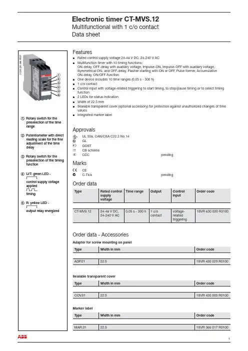
FeaturesRated control supply voltage 24-48 V DC, 24-240 V AC Multifunction timer with 10 timing functions:ON-delay, OFF-delay with auxiliary voltage, Impulse-ON, Impulse-OFF with auxiliary voltage, Symmetrical ON- and OFF-delay, Flasher starting with ON or OFF , Pulse former, Accumulative ON-delay, ON/OFF-functionOne device includes 10 time ranges (0.05 s - 300 h)1 c/o contactControl input with voltage-related triggering to start timing, to stop/pause timing or to select timing function2 LEDs for status indication Width of 22.5 mmSealable transparent cover (optional accessory) for protection against unauthorized changes of time valuesIntegrated marker label½½½½½½½½½ApprovalsA UL 508, CAN/CSA C22.2 No.14C GL D GOSTK CB scheme ECCCpendingMarksa CE bC-TickpendingOrder dataOrder data - AccessoriesAdapter for screw mounting on panelSealable transparent coverMarker labelᕃᕆᕇᕄᕅᕈ2C D C 251 048 F 0t 07ቢ Rotary switch for thepreselection of the time range ባ Potentiometer with directreading scale for the fi ne adjustment of the time delay ቤ Rotary switch for thepreselection of the timing function ብ U/T: green LED -Vcontrol supply voltage applied W timing ቦ R: yellow LED -Voutput relay energizedApplicationThe CT -S range timers are designed for use in industrial applications. They operate over a universal range of supply voltages and a large time delay range, within compact dimensions. The easy-to-set front-face potentiometers, with direct reading scales, provide accurate time delay adjustment.Multifunction timers are ideally suited for service and maintenance applications, because one device can replace a number of time relays with different functions, voltage and time ranges. This reduces inventory and saves money.Operating modeThe CT -MVS.22 with 2 c/o contacts offers 11 timing functions. The function is rotary switch selectable on the front of the unit. Each function is indicated by an international function symbol.One of 10 time ranges, from 0.05 s - 300 h, can be selected with an other rotary switch. The fi ne adjust-ment of the time delay is made via an internal potentiometer, with a direct reading scale, on the front of the unit.Timing is displayed by a fl ashing green LED labelled U/T.Function diagramsRemarksLegend:G Control supply voltage not applied / Output contact open B Control supply voltage applied / Output contact closed A1-Y1/B1 Control input with voltage-related triggeringTerminal designations on the device and in the diagrams:The c/o contact is designated 15-16/18. Control supply voltage is applied to terminals A1-A2. Function of the yellow LED:The yellow LED R glows as soon as the output relay energizes and turns off when the output relay de-energizes.A ON-delayThis function requires continuous control supply voltage for timing. Timing begins when control supply voltage is applied. The green LED fl ashes during timing. When the selected time delay is complete, the output relay energizes and the fl ashing green LED turns steady. If control supply voltage is interrupted, the output relay de-energizes and the time delay is reset.15-18A1-A215-162C D C 252 011 F 0207green LEDt = adjusted time delayFunction diagramsA + Accumulative ON-delayThis function requires continuous control supply voltage for timing. Timing begins when control supply voltage is applied. The green LED fl ashes during timing. When the selected time delay is complete, the output relay energizes and the fl ashing green LED turns steady. Timing can be paused by closing control input A1-Y1/B1. The elapsed time t 1 is stored and continues from this time value when A1-Y1/B1 is re-opened. This can be repeated as often as required. If control supply voltage is interrupted, the output relay de-energizes and the time delay is reset.B OFF-delay with auxiliary voltageThis function requires continuous control supply voltage for timing.If control input A1-Y1/B1 is closed, the output relay energizes immediately. If control input A1-Y1/B1 is opened, the time delay starts. The green LED fl ashes during timing. When the selected time delay is complete, the output relay de-energizes and the fl ashing green LED turns steady.If control input A1-Y1/B1 recloses before the time delay is complete, the time delay is reset and the out-put relay does not change state. Timing starts again when control input A1-Y1/B1 re-opens. If control supply voltage is interrupted, the output relay de-energizes and the time delay is reset.AB Symmetrical ON- and OFF-delayThis function requires continuous control supply voltage for timing.Closing control input A1-Y1/B1 starts the ON-delay t 1. When timing is complete, the output relay ener-gizes. Opening control input A1-Y1/ B1 starts the OFF-delay t 2. Both timing functions are displayed by the fl ashing green LED. When the OFF-delay t 2 is complete, the output relay de-energizes.If control input A1-Y1/B1 opens before the ON-delay t 1 is complete, the time delay is reset and the out-put relay remains de-energized. If control input A1-Y1/B1 closes before the OFF-delay t 2 is complete, the time delay is reset and the output relay remains energized.If control supply voltage is interrupted, the output relay de-energizes and the time delay is reset.15-18t A1-A2 15-16A1-Y1/B12C D C 252 016 F 0207green LEDt = adjusted time delay1 + t2 = tt 3 = pause timing15-1615-18A1-A2 A1-Y1/B12C D C 252 014 F 0207green LEDt = adjusted time delay15-1615-18t A1-A2 A1-Y1/B12C D C 252 018 F 0207green LED1 = adjusted ON-delay t2 = adjusted OFF-delay t 1 = t 2Function diagramsCA Impulse-ONThis function requires continuous control supply voltage for timing.The output relay energizes immediately when control supply voltage is applied and de-energizes after the set pulse time is complete. The green LED fl ashes during timing. When the selected pulse time is com-plete, the fl ashing green LED turns steady.If control supply voltage is interrupted, the output relay de-energizes and the time delay is reset.CB Impulse-OFF with auxiliary voltageThis function requires continuous control supply voltage for timing.If control supply voltage is applied, opening control input A1-Y1/B1 energizes the output relay immedi-ately and starts timing. The green LED fl ashes during timing. When the selected pulse time is complete, the output relay de-energizes and the fl ashing green LED turns steady.Closing control input A1-Y1/B1, before the pulse time is complete, de-energizes the output relay and resets the pulse time.If control supply voltage is interrupted, the output relay de-energizes and the time delay is reset.DE Flasher, starting with ON or OFFApplying control supply voltage starts timing with symmetrical ON / OFF times. The cycle starts with an ON time fi rst.Closing control input A1-Y1/B1, with control supply voltage applied, starts the cycle with an OFF time fi rst. The ON / OFF times are displayed by the fl ashing green LED, which fl ashes twice as fast during the OFF time.If control supply voltage is interrupted, the output relay de-energizes and the time delay is reset.H Pulse formerThis function requires continuous control supply voltage for timing.Closing control input A1-Y1/B1 energizes the output relay immediately and starts timing. Operating the control contact switch A1-Y1/B1 during the time delay has no effect. The green LED fl ashes during tim-ing. When the selected ON time is complete, the output relay deenergizes and the fl ashing green LED turns steady. After the ON time is complete, it can be restarted by closing control input A1-Y1/B1. If control supply voltage is interrupted, the output relay de-energizes and the time delay is reset.15-18A1-A2 15-162C D C 252 020 F 0207green LEDt = adjusted pulse time15-1615-18A1-Y1/B1A1-A2 2C D C 252 022 F 0207green LEDt = adjusted pulse time15-18A1-A2 A1-Y1/B115-162C D C 252 024 F 0207green LEDt = adjusted flashing time15-18A1-A2 15-16A1-Y1/B12C D C 252 026 F 0207green LEDt = adjusted pulse timeFunction diagramsG ON/OFF-functionThis function is used for test purposes during commissioning and troubleshooting.If the selected max. value of the time range is smaller than 300 h (front-face potentiometer “Time sector” not 300 h), applying control supply voltage energizes the output relay immediately and the green LED glows. Interrupting control supply voltage, de-energizes the output relay.If the selected max. value of the time range is 300 h (front-face potentiometer “Time sector” = 300 h) and control supply voltage is applied, the green LED glows, but the output relay does not energize. Time settings and operating of the control inputs have no effect on the operation.Connection diagram15-16/18 1. c/o contactA1-A2Rated control supply voltage U S 24-48 V DC or 24-240 V AC A1-Y1/B1Control inputWiring instructionsControl input(voltage-related triggering)The control input Y1/B1 is triggered with electric potential against A2. It is possible to use the control supply voltage from terminal A1 or any other voltage within the rated control supply voltage range.15-18A1-A215-162C D C 252 028 F 0207green LEDTime sector ≠ 300 hTime sector = 300 hY1/A1A1B115A2161815Y1/B11816A22C D C 252 004 F 0b 06L(+)N(-)2C D C 252 102 F 0b 06L(+)L(+)N(-)L(-)2C D C 252 103 F 0b 06Technical dataData at T= 25 °C and rated values, if noting else indicatedaTechnical diagramsLoad limit curveA C v o l t a g e [V ]D C v o l t a g e [V ]2C D C 252 150 F 0206AC load (resistive)DC load (resistive)Derating factor Fcos ϕD e r a t i n g f a c t o r F2C D C 252 124 F 0206Contact lifetimeS w i t c h i n g c y c l e s2C D C 252 148 F 0206Dimensionsin mmCT -MVS.122C D C 252 188 F 0b 05Dimensions accessoriesin mmADP .01 - Adapter for screw mounting on panelCOV .01 - Sealable transparent coverMAR.01 - Marker labelSynonymsUsed expression Alternative expression(s)Used expression Alternative expression(s)1 c/o contact1 SPDTvoltage-relatedwet / non-fl oating2C D C 252 187 F 00052C D C 252 185F 00052C D C 252 186 F 0005As part of the on-going product improvement, ABB reserves the right to modify the characteristics of the products described in this document. The information given is non-contractual. For further details please contact (/contacts) the ABB company marketing these products in your country.D o c u m e n t n u m b e r : 2C D C 111 089 D 0201 (08/2007)ABB STOTZ-KONTAKT GmbHEppelheimer Strasse 82, 69123 Heidelberg, Germany Postfach 10 16 80, 69006 Heidelberg, GermanyInternet /lowvoltage Ǟ Control Products。

文案大全此文档由恒飞电器提供 由杭州寰宇世极功放编写※系统概述:M P 3智能音乐播放器:采用世界最先进的微电脑控制技术。
将广播自动分区播放、外部音频和麦克风录音存储等先进功能综合为一体。
内存大小由你选择: (分别可用U 盘或T F 卡设计),成为广播设备的典范之精品,达到国内领先水平。
广泛适用于校园自动广播音乐打铃、外语广播教学听力考试系统。
※综合功能:M P 3自动广播、智能分区广播、日常教学广播、消防紧急广播、背景音乐播放、外语教学及听力考试广播功能。
※技术参数:信噪比:>90d B ; 谐波失真:<0.1%;频响范围:20H z -18K ; 电压:220V※前面板介绍(由于机型不同布局略有不同)01、电源灯及开关02、插U 盘或连接电脑U S B 囗03、电源灯 (T F 卡插囗)04、显示屏;05、菜单上,下,左,右控制选择键; 06、确定,停止,返回键; 07、咪,输入,监听音量控制键; 08、分区1,2,3,4,5,6按键 09、分区及电源全开全关按键; 10、手动与自动切换按键;重要提示:当你插入新U 盘或TF 卡时,必须先把它插在本机上并开关本机电源,让它自动生成AUDIO 文件夹后并把有编号的MP3歌曲装到AUDIO 文件夹内才可以播放。
※后面板介绍(由于机型不同布局略有不同)2注:短路输入端囗: 当这个端囗有短路信号输入时,本机会立刻播放你放在內存里AL A RM 文件夹内的这一首曲目,AL A RM 这文件夹內只能放一首用于紧急报警用的歌曲,其它需要定时播放的歌曲要放在A U DI O 文件夹內,如歌曲的路径放错则定时播放将不执行。
短路输出端囗: 这个端囗与功放电源和分区的动作同步,即当有定时点到时,这端囗即短路,当定时歌曲放完或设定了结束时间到了即断开,这端囗作用是用于控制电源时序器接多台功放之用。
※设备连接图(由于机型不同布局略有不同)※音乐播放步骤一:按面板上的” 确定” 键,进入主菜单。
CX-T02型、CX-T03型可编程多功能电子定时器使用说明书一、产品简介:CX-T02型、CX-T03型可编程多功能电子定时器,是一个以微电脑处理器为核心配合电子电路等组成的电源开关控制装置。
它可预设定每天或一周内20次不同时间的开/关控制,还具有倒计时、任意循环定时、键盘锁定功能和12/24小时制转换功能。
本机内置一枚可充电镍氢电池作为备用电源,在脱离市电电源的情况下,仍可保持计时显示和储存的各项数据达9个月以上。
它采用便携式移动插头形式和微功耗待机电路,可以控制电热水器、电饭煲、饮水机、电动自行车限时充电控制、灯具等各种电器。
您使用本产品后,各种电器将根据您的要求实现自动开启和关闭,既省电又方便,是真正的节电产品。
二、技术参数:执行标准:GB/T14536.1-1998 GB/T14536.8-1996额定电压:220V ~50Hz额定电流:CX-T02型10A(阻性)CX-T03型16A(阻性)工作温度:-20~70℃计时误差:≤±1秒/天三、系统功能介绍:1.液晶全屏字符,如右图所示:2. 本机在时钟状态下,按“模式”键可将工作状态设定为所需的方式。
设定顺序为:关自动开循环 Z Z(倒计时)关电源输出处于经常关闭状态。
自动电源输出处于执行编写的定时开/关程序状态。
开电源输出处于经常开启状态。
循环电源输出按照您设定的开启时间长度和间隔时间长度(关闭时长)来循环工作。
Z Z电源输出处于倒计时(延时关机)状态,最长时间为 23小时59分,最短为1分钟。
C 按此键后系统将清除所有储存的数据,系统恢复到初始状态。
四、操作方法在本机进入时钟状态后,可按以下方法进行操作:(一)、校正星期和时间:按“模式”键将定时器工作状态设定为“关”,在此状态下左手按住“时钟”键不放,右手按“日期”键,将星期调整为当前日期,调整好日期(星期)后再按“时”和“分”键将时钟调整为当前的标准时间。
(二)、设定倒计时(延时关机)时间:按“模式”键将工作状态切换至Z Z状态,电源输出即处于开启状态(初始默认时间为8小时),屏幕显示如右图所示:在此状态下,按“时”或“分”键修改您所需要本机开启通电的时间,每按一次“时”或“分”键,时间将减少1小时或1分钟,最大设定时间为23小时59分。
CX-T02C、CX-T03C型可编程时间(温度)电子定时器使用说明书一、产品简介:CX-T02C、CX-T03C型可编程时间(温度)定时器,是一个以单片微处理器为核心配合电子电路等组成的一个电源开关控制装置。
它可预设定每天或一周内8次不同时间的开/关控制,并具有温度自动控制功能、键盘锁定功能和12/24小时制转换功能。
本机内置一枚可充电镍氢电池作为备用电源,在脱离市电电源的情况下,仍可保持计时显示和储存的各项数据达9个月以上。
它可以按时间或温度控制各种电器的自动定时开关。
二、技术参数:执行标准:GB/T14536.1-1998 GB/T14536.8-1996额定电压:220V ~ 50Hz额定电流:CX-T02C 10A (国标插头标准)CX-T03C 16A (国标插头标准)工作温度:-20~70℃计时误差:≤±1秒/天温控范围:0~99℃温控误差:≤±1℃三、系统功能介绍:1.液晶全屏字符和外形尺寸,如右图所示:2. 按“模式”键可将工作状态设定为所需的方式,设定顺序为:取暖开自动关制冷。
3.在不带温控和没有设定温度时:从开自动时,定时器即开启,在到达设定的自动关闭时间程序时才关闭。
从关自动时,定时器即关闭,在到达设定的自动开启时间程序时才开启。
关电源输出处于经常关闭状态。
自动电源输出处于执行编写的定时开/关程序状态。
开电源输出处于经常开启状态。
取暖设定的温度值高于当前温度时,定时器自动开启,温度设定范围0~99℃。
制冷设定的温度值低于当前温度时,定时器自动开启,温度设定范围0~99℃。
四、操作方法在本机进入时钟状态后,可按以下方法进行操作:工作状态操作方法功能开/自动/关按“时钟”键 +“星期”键修改当前星期开/自动/关按“时钟”键 +“时”键修改当前时间(小时)开/自动/关按“时钟”键 +“分”键修改当前时间(分)开/自动/关按“时钟”键 +“设定”键转换12/24小时制式开/自动/关按“时钟”键 +“模式”键转换夏时制开/自动/关按“时钟”键 +“S/A”键3秒键盘锁定和键盘解锁开/自动/关按“定时”键进入开/关程序(PRG)编写状态编程(PRG)状态按“星期”键进行编写程序中的星期选择编程(PRG)状态按“时”键进行编写程序中的时间(小时)选择编程(PRG)状态按“分”键进行编写程序中的时间(分)选择编程(PRG)状态按“S/A”键清除当前输入的程序和恢复最近的程序编程(PRG)状态按“时钟”键退出编程,返回时钟状态(一)、校正星期和时间:左手按住“时钟”键不放,右手按“星期”键,将星期调整为当前日期,调整好日期(星期)后再按“时”和“分”键将时钟调整为当前的标准时间。
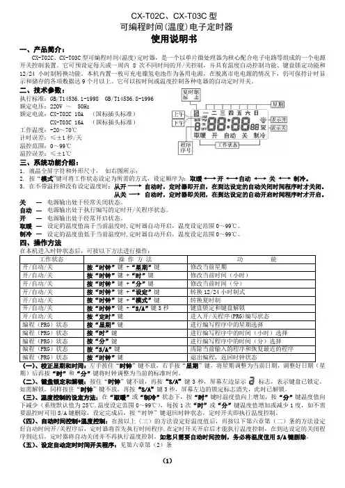
遥控器定时程序操作详解光催化空气净化消毒器壁挂式,柜式,移动式三种使用的遥控器定时程序相同。
现单拿壁挂式LTS-B832/2做定时操作说明。
在设定定时程序前首先确定设备上时钟显示的时间是否正确,若不正确则使用遥控器上“对时”键和“+”,“—”键进行时间调节。
详见说明书。
在时钟显示正确后便可以进行定时操作例:医院手术室想要每天上午08:00到11:00进行光催化消毒一次,下午14:00到17:00进行光催化消毒一次。
晚上00;00到01:00进行臭氧消毒一次。
操作如下,按下遥控器上“催化调节”键可发现显示屏左侧出现“日历1”“定开”然后小时的数字在闪烁,按“+”“—”键调节数字到08,然后接着按下“催化调节”键就会跳到分钟的数字在闪烁,按“+”“—”键调节数字到00。
定开的时间就设定好了。
接着按下“催化调节”键显示屏左侧出现“日历1”“定关”然后小时的数字在闪烁,按“+”“—”键调节数字到11,然后接着按下“催化调节”键就会跳到分钟的数字在闪烁,按“+”“—”键调节数字到00。
上午的光催化定时时段就设定好了。
接着按下“催化调节”键可发现显示屏左侧出现“日历2”“定开”然后小时的数字在闪烁,按“+”“—”键调节数字到14,然后接着按下“催化调节”键就会跳到分钟的数字在闪烁,按“+”“—”键调节数字到00。
定开的时间就设定好了。
接着按下“催化调节”键显示屏左侧出现“日历2”“定关”然后小时的数字在闪烁,按“+”“—”键调节数字到17,然后接着按下“催化调节”键就会跳到分钟的数字在闪烁,按“+”“—”键调节数字到00。
下午的光催化定时时段就设定完毕。
在光催化定时时段设定完毕后,要启动程序就按下“催化定时”键,让显示屏上显示出“日历1”和“日历2"。
当显示屏上左侧无任何显示时,则定时程序未启动。
臭氧定时操作同光催化定时操作是相同的,只是臭氧的“日历1”,“日历2”在显示屏的右侧显示。
遥控操作按钮也在遥控器右侧。
定时器说明书定时器说明书定时器-NHR-2100系列数显定时器使用说明书一、产品介绍定时器-NHR-2100系列数显定时器采用全自动贴片封装工艺,具有很强的抗干扰能力。
六位LED数码显示,显示范围宽。
带多种输出功能:定时报警控制、计时报警控制、485/232通讯、200mS脉宽输出等,计时功能可带按键启动、停止、清零功能,并可选外接按钮。
功能强大,适用于各种场合。
三、仪表面板 1)面板指示:PV:显示测量值;在参数设定状态下,显示参数符号和参数值A/T:定时功能时PV显示当前时间时分秒,指示灯亮;计时功能时PV显示累计时间时分秒,指示灯亮。
B/D:定时功能时PV显示年月日,指示灯亮AL1:报警指示灯AL2:备用 Hz:备用 C:备用T:计时器、定时器指示灯亮注:外形尺寸为96*48mm时,无Hz、C、T指示灯。
1四、参数设置 1)菜单设置★注:选择计时功能时,参数“T1”和“T2”、“T3”无效,并且进入菜单设置时不显示“T1”和“T2”、“T3”。
选择定时功能时,参数“A-MODE”,并且进入菜单设置时不显示“A-MODE”。
2)参数设置(以更改通讯地址为例)23)参数说明A、通讯设置参数说明:B、功能设置参数说明:C、定时计时设置参数说明:3注:选择计时功能时,参数“T1”和“T2”、“T3”无效,并且进入菜单设置时不显示“T1”和“T2”、“T3”。
选择定时功能时,参数“A-MODE”无效,并且进入菜单设置时不显示“A-MODE” ,默认定时时间到就报警。
五、仪表接线图注:不同外型仪表后盖接线端子的方向不一样,见示意图六、仪表选型X/□1/□/□X-□ NHR-2100□-□定时器① ②③ ④⑤ ⑥4NHR-2100定时器没有脉宽输出与外部事件输入功能,用“X”补上。
型号举例:NHR-2100A-X/D1/X-A5。
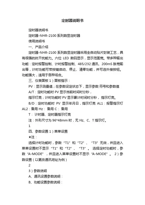
本说明书适用于天美时 T2P103DH 、T49866等采用Intelligent Quartz智能石英机芯的手表。
飞返计时器第4中间指针调节重新调节第4 中间指针的步骤:1.把表冠拔到如上图所示的.和两个指针分别会自动重置到所在弧线的开始端。
2.第4中间指针应该指向12点钟的位置。
如果第4中间指针在拉出表冠到最外部的位置后的5秒钟内没有指向12点钟的位置,可以按按钮A或者B来逆时针或者顺时针移动该指针直到它指向12点钟的位置。
3.把拔出的表冠推回到“关闭位置”-第二时区最上面的指针“Upper hand”显示第二时区的时间。
注意它的刻度是24小时。
午夜时指针可以在两端。
中午时在中间位置。
通常来说,时区的差异是按小时递增的。
在这种情况下,第二时区的分钟值和手表的分针所指向的时间一致。
怎样调节第二时区:1.把表冠拉到中间档。
上针显示第二时区的时间,第4中针显示第二时区的分钟数。
2.假设第二时区的时间和第一时区(当前时区)拥有相同的分钟数,第4中针应该和第一时区的分针指向同一刻度。
如果这两个指针指向不一致,或者如果第二时区的分钟和第一时区不一样,按按钮B来移动第4中针到期望的位置。
3.按按钮A来移动上针(按一个小时递增)来调节时间。
按住按钮A可以快速移动上针。
4.设置完成后,推进拔出的表冠。
飞返计时器该手表提供一个4小时的飞返计时器。
1.按按钮A启动。
第4中针显示以0.2秒精度的秒数。
底针显示分钟的最后一位数字,改数字最大为10并一直重复。
上针显示总时间,包含时和分,以10分钟为单位。
计时器记可以记时到4个小时直到自动停止。
2.再按一下按钮A可以停止计时器。
所有的指针都会停止转动。
3.可以按按钮A来恢复计时器。
4.按按钮B来重置飞返计时器到零位置。
计时器重置后,所有的指针都会回到0位置。
8秒钟后,手表恢复显示第二时区的时间。
5.当计时器运行时,按住按钮B可以重置,重启飞返计时器。
松开按钮B会重启计时器。
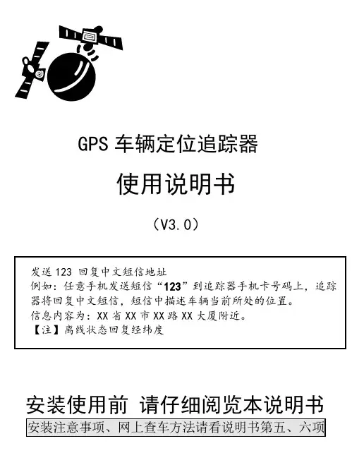
GPS车辆定位追踪器使用说明书(V3.0)发送123 回复中文短信地址例如:任意手机发送短信“123”到追踪器手机卡号码上,追踪器将回复中文短信,短信中描述车辆当前所处的位置。
信息内容为:XX省XX市XX路XX大厦附近。
【注】离线状态回复经纬度安装使用前请仔细阅览本说明书安装注意事项、网上查车方法请看说明书第五、六项一、常用指令1.任意手机编辑短信CQ发送到定位器手机卡号可以重启定位器。
2.任意手机编辑短信SZCS,123456,JZ=0发送到定位器手机卡号可以关闭基站定位。
出厂设置JZ=1(默认是打开)二、技术参数1.GPS性能跟踪灵敏度:<-160dBm启动时间:冷启动45秒、热启动3秒定位精度: 10米速度精度: 0.3米/秒2.GSM性能频率: GSM 900/1800最大发射功率: 1W3.整机主要技术参数整机尺寸:86mm×54mm×16mm工作电压: 9V~30V最大工作电流: < 250mA(12V)普通模式工作电流: < 15mA(12V)工作温度: -20 ℃~ +70 ℃工作湿度: 20 ~ 95%三、状态指示追踪器侧面有3个指示灯,用于指示运行状态1.SIM卡指示灯灯的状态含义长亮设备开机且SIM卡正常慢闪设备开机但SIM卡不正常灭设备未开机2.GSM信号强度指示灯灯的状态含义长亮信号4格(满格)慢闪信号3格快闪信号1-2格灭无信号3.GPS信号强度指示灯灯的状态含义长亮成功定位慢闪可以搜到卫星但不能定位快闪GPS模块在工作但没搜到星灭GPS模块被关闭或工作不正常四、安装方法1.安装SIM卡打开SIM卡仓盖,插入SIM卡并扣紧,关闭SIM卡仓盖。
2.安装主机建议由经销商指定的专业机构进行安装,并注意以下事项:1)为避免窃贼破坏,主机安装应尽量隐蔽;2)避免与发射源放在一起,比如倒车雷达、其它车载通讯设备等;3)避开高温、高湿的环境;4)使用捆扎带或双面胶贴固定,以免影响振动检测的效果;5)GPS天线为内置,则主机安装时务必保证正面朝上,且上方无金属物遮挡;3.安装电源线1)本设备标准供电为9V-30V,红色线为电源正极,黑色为电源负极;2)电源负极请选择单独接地,搭铁,勿与其它地线共接;五、使用说明产品的正确使用步骤如下:安装→开机→短信(或网上)操作接通车辆电源后,设备将会自动开机。
ZD-B03/D03使用说明书产品功能周定时循环开关功能,即,以周为单位,循环开关,每天最多设置24条(12组)开关命令。
举例:每周的周一到周五6点开7点关,10点再开,12点再关,最多24条。
适用范围:需要每天固定时间开关多次的电器设备,如苗圃浇灌、雨林缸等。
使用说明:按键说明定时键:①设置定时②长按2秒可以进入上一次所设置完成的定时程序的查看和修改画面时钟键:设置定时器当前的时钟时间取消键:①取消当前正在进行的设置行为,之前所设置的内容无效,不会被保留②长按2秒钟可以取消正在运行的定时程序,进入无定时状态开关键:更改定时器当前的开关状态左右键:设置定时或设置时钟的过程中移动光标的位置+ - 键:控制光标所在位置数值的变化确定键:确定并执行正在设置的内容复位键:重新启动定时器使用说明:一、无论设置定时,设置时钟还是设置开关状态,都需要按确定键后才能设置有效。
二、设置时钟→先按时钟键→按左右键移动光标位置,按“+ -”切换数值变化→按确定键设置完成三、设置定时→先按定时键→左右键移动光标位置,按“+ -”键切换数值变化,根据自身需要设置具体星期组合、开关时间和开关命令(星期组合可以任意设置)→将光标移动到下一条位置并按确定键进入下一条的设置画面→根据自身需要重复上面的步骤依次设置最多24条开关命令(在设置过程中可以通过上一条和下一条查看和修改所设置的开关命令,非常方便)→按确定设置完成四、查看和修改定时按住定时键不放2秒钟后进入上一次设置完成的定时设置画面,可以通过上一条和下一条查看原来的设置是否有错误,并可以直接进行修改,然后按确定开始执行修改后的程序五、设置开关状态→先按开关键→继续按开关键切换当前的开关状态→按确定键设置完成六、取消定时按住取消键不放2秒钟可以取消正在运行的定时程序,进入无定时状态,开关状态保持不变使用案例说明假如您公司的饮水机需要在周一到周五的上午7点钟开启,晚12点钟关闭,下午2点钟开启,晚上9点关闭→先按定时键→将光标移动到星期的位置,通过“+-”键切换星期组合为周一到周五,即将周一到周五显示,周六周日不显示(默认为全部显示)→设置第一条命令为7点开→将光标移动到下一条位置,并按确定→设置第二条命令为12点关(星期组合默认跟上一条保持不变)→重复上面的步骤设置第三条为14点开,设置第四条为21点关→按确定键设置完毕,插上电源以后定时器会在周一到周五按时开关产品规格额定电压:220V 最大电流:B03 10A / D03 15A工作频率:50HZ 最大功率:B03 2200W / D03 3200W固有损耗:≤2W 可编程数:24条(12组)×7天时间设置范围:1秒~1周可设置精度:1秒电池:内置可充电电池特殊情况说明1、当有定时程序正在执行时,进入设置画面,则定时程序转入后台照常执行,不会因为进入设置过程而中断定时程序的执行,只有用户设置完新程序并按确定键后,才会擦除原有的定时程序而执行新的定时程序。
CX-T02(W)型、CX-T03型可编程多功能电子定时器使用说明书一、产品简介:CX-T02(W)型、CX-T03型可编程多功能电子定时器,是以微电脑处理器为核心配合电子电路等组成的电源开关控制装置。
它可预设定每天或一周内20次不同时间的开/关控制,还具有倒计时、任意循环定时、键盘锁定功能和12/24小时制转换功能。
本机内置一枚可充电镍氢电池作为备用电源,在脱离市电电源的情况下,仍可保持计时显示和储存的各项数据达9个月以上。
它采用便携式移动插头形式和微功耗待机电路,可以控制电热水器、电饭煲、饮水机、电动自行车限时充电控制、灯具等各种电器。
您使用本产品后,各种电器将根据您的要求实现自动开启和关闭,既省电又方便,是真正的节电产品。
二、技术参数:执行标准:GB/T14536.1-2008 GB/T14536.8-2010额定电压:220V ~50Hz额定电流:CX-T02(W)型10A(阻性)CX-T03型16A(阻性)工作温度:-20~70℃计时误差:≤±1秒/天三、系统功能介绍:1.液晶全屏字符,如右图所示:2. 本机在时钟状态下,按“模式”键可将工作状态设定为所需的方式。
设定顺序为:关自动开循环 Z Z(倒计时)关电源输出处于经常关闭状态。
自动电源输出处于执行编写的定时开/关程序状态。
开电源输出处于经常开启状态。
循环电源输出按照您设定的开启时间长度和间隔时间长度(关闭时长)来循环工作。
Z Z电源输出处于倒计时(延时关机)状态,最长时间为 23小时59分,最短为1分钟。
C 按此键后系统将清除所有储存的数据,系统恢复到初始状态。
S/A 时钟状态时夏时制转换、12/24小时制转换的按键,在设定自动程序时是清除数据的按键。
模式工作状态功能转换的按键。
四、操作方法在本机进入时钟状态后,可按以下方法进行操作:(一)、校正星期和时间:按“模式”键将定时器工作状态设定为“关”,在此状态下左手按住“时钟”键不放,右手按“星期”键,将星期调整为当前日期,调整好日期(星期)后再按“时”和“分”键将时钟调整为当前的标准时间。
SZ12-ZYT02微电脑时控开关货号:602wxr9ld0426使用说明书◆使用之前请务必仔细阅读本说明书,以便正确使用本产品。
◆读后请将说明书妥善保管。
功能和用途:本产品能根据用户设定的时间,自动打开和关闭各种用电设备的电源。
控制对象可以是路灯、霓虹灯、广告招牌、生产设备、广播电视设备等一切需要定时打开和关闭的电器设备和家用电器。
性能指标:◆标准工作电源220V/50Hz◆计时误差<±2秒/天◆适用电源范围160~240V◆环境温度-25~60℃◆开关容量阻性16A感性10A◆相对温度<95%◆消耗功率<4VA ◆外形尺寸50×100×74mm◆时控范围1分~168小时◆重量160g◆有10组开关时间,手动、自动两用显示屏显示符号解释操作说明定◆7、检查完后,再按"时钟"键,使显示屏显示当前时间;◆8、按“自动/手动”键,将继电器调至当前控制设备开关状态,再将显示屏下方符号"AOTO"(自动)调至出现,时设置 ◆1、先检查时钟显示是否与当前时间一致,如需重新准,按住“时钟”键的同时,查看显示屏所显示的时间是否与当前时间一样。
分别按住“校星期”、“校时”、“校分”键,将时钟调到当前时间;◆2、按一下“定时”键,显示屏左下方出现“1开”字样(表示第一次开启时间)。
然后按“校星期”选择五天工作制、每日相同、每日不同的工作模式,再按“校时”、“校分”键,输入所需开启的时间; ◆3、再按一下“定时”键,显示屏左下方出现“1OFF”字样(表示第一关闭时间),再按“校星期”、“校时”、“校分”键,输入所需关闭的日期和时间;◆4、继续按动“定时”键,显示屏左下方将依次显示“2ON、2OFF、3ON、3OFF、……、10ON、10OFF”,参考步骤2、3设置以后各次开关时间。
◆5、如果每天不需设置10组开关,,则必须按“取消/恢复”键,将多余各组的时间消除,使其在显示屏上显示“--:--”图样(不是00:00);◆6、定时设置完毕时,应按“时钟”键检查各次定时设定情况,是否与实际情况一致,若不一致,请按校时、校分、校星期时行调整或重新设定;此时,时控开关才能根据所高设定的时间自动开关、关电路。