【书评】成功的交易80%靠心理,只有20%靠方法-自律的交易者
- 格式:pdf
- 大小:218.57 KB
- 文档页数:3

FireFa ce800中文说明及设置之前本站的一位朋友传给我的,在此分享给大家,(FF400同样适用)FIREFA CE800使用说明感谢您选择了Firef ace 800,如果您在购买FFace800之前没有使用过RME公司生产的其他产品,建议您还是耐心的把这片文章看完,否则在使用中您会遇到很多问题,祝您阅读中有所收获。
Firefa ce 800是RM E公司在经过了两年多的开发和研制后,制造出来的一款具有24bit/192kHz的火线专业音频接口,它配备了丰富的模拟和数字接口,总共有28个通道的输入输出端口。
其中包括:● 8个平衡方式的模拟输入/输出接口。
● 2组ADAT数字输入/输出接口。
(每路ADAT可以同时传输8路信号,并且可以用来传输SPD IF信号使用)●4路前置☒话放。
●还包括 ☒ordclo ck同步输入/输出。
●✋✋☒输入/输出。
●一路耳机☒监听。
还支持时间码同步可选择LTC,Video和VITC。
并且他支持多种计算机操作系统,window s 2000 SP4, window s XP , XP 64.Mac os X和MacOS X x86.它的驱动安装也十分简单。
FIREFA CE800的安装,这里我先介绍PC的安装方法首先要从http://www.rme-audio.com/englis h/downlo ad/driver s.htm下载一个FO R window s的驱动解压缩.fut_wi n_fir e.zip将我们的Fi refac e 800通过1394火线与电脑连接,打开Fire face800电源开关,计算机会检测到新硬件,系统检测到新硬件会弹出这个对话筐,我们选择从列表或指定位置安装(高级),选择驱动解压后的路径。
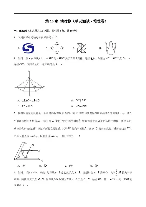
第13章轴对称(单元测试·培优卷)一、单选题(本大题共10小题,每小题3分,共30分)1.下列图形中是轴对称图形的是()A .B .C .D .2.如图,点A 在直线l 上,△ABC 与AB C '' 关于直线l 对称,连接BB ',分别交AC ,AC '于点D ,D ¢,连接CC ',下列结论不一定正确的是()A .BACB AC ∠=∠''B .CC BB '' C .BD B D =''D .AD DD ='3.我们知道光的反射是一种常见的物理现象.如图,某V 型路口放置如图所示的两个平面镜1l ,2l ,两个平面镜所成的夹角为1∠,位于点D 处的甲同学在平面镜2l 中看到位于点A 处的乙同学的像,其中光的路径为入射光线AB 经过平面镜1l 反射后,又沿BC 射向平面镜2l ,在点C 处再次反射,反射光线为CD ,已知入射光线2AB l ∥,反射光线1CD l ∥,则1∠等于()A .40︒B .50︒C .60︒D .70︒4.如图,已知a b ∥,直线l 与直线a ,b 分别交于点A ,B ,分别以点A ,B 为圆心,大于12AB 长为半径画弧,两弧相交于点M ,N ,作直线MN 分别交直线a ,b 于点D 、C ,连接AC ,若135∠=︒,则BAD ∠的度数是()A .35︒B .55︒C .65︒D .70︒5.如图,在等腰Rt ABC △,90BAC ∠=︒,AB AC =,BD 为ABC V 的角平分线,过点C 作CE BD ⊥交BD 的延长线与点E ,若2CE =,则BD 的长为()A .3B .4C .5D .66.如图,90ACB AED ∠=∠=︒,CAE BAD ∠=∠,BC DE =,若BD AC ∥,则ABC ∠与CAE ∠间的数量关系为()A .2ABC CAE∠=∠B .ABC CAE ∠=∠C .290ABC CAE ∠+∠=︒D .2180ABC CAE ∠+∠=︒7.某平板电脑支架如图所示,其中AB CD =,EA ED =,为了使用的舒适性,可调整AEC ∠的大小.若AEC ∠增大16︒,则BDE ∠的变化情况是()A .增大16︒B .减小16︒C .增大8︒D .减小8︒8.如图,在ABC V 中,80BAC ∠=︒,边A 的垂直平分线交BC 于点E ,边AC 的垂直平分线交AC 于点F ,连接AE ,AG .则EAG ∠的度数为()A .35︒B .30︒C .25︒D .20︒9.如图,在Rt △ABC 中,∠ACB =90°,AC =3,BC =4,AD 是△ABC 的角平分线,若P ,Q 分别是AD 和AC 边上的动点,则PC +PQ 的最小值是()A .65B .2C .125D .5210.如图,在ABC V 中,90BAC ∠=︒,A 是高,BE 是中线,C 是角平分线,C 交A 于G ,交BE 于H ,下面说法:①ACF BCF S S = ;②AFG AGF ∠=∠;③2FAG ACF ∠=∠;④BH CH =.其中正确的是()A .①②③④B .①③C .②③D .①③④二、填空题(本大题共8小题,每小题4分,共32分)11.如图,在ABC V 中,分别以点B 和点C 为圆心,大于12BC 的长为半径画弧,两弧相交于点M 、N ,作直线MN ,交AB 于点D ,连接CD ,若ABC V 的周长为24,9BC =,则ADC △的周长为.12.如图,直线m n ∥,点A 是直线m 上一点,点B 是直线n 上一点,AB 与直线m ,n 均不垂直,点P为线段AB 的中点,直线l 分别与m ,n 相交于点C ,D ,若90,CPD CD ∠=︒=m ,n 之间的距离为2,则PC PD ⋅的值为.13.如图,A EGF ∠=∠,F 为BE CG ,的中点,58DB DE ==,,则AD 的长为.14.如图所示,在平面直角坐标系中,ABC V 满足45,90BAC CBA ∠=︒∠=︒,点A ,C 的坐标分别是()()2,0,3,5--,点B 在y 轴上,在坐标平面内存在一点D (不与点C 重合),使ABC ABD △≌△,且AC 与AD 是对应边,请写出点D 的坐标.15.如图,60AOB ∠=︒,C 是BO 延长线上一点,12cm OC =,动点M 从点C 出发沿射线CB 以2cm /s 的速度移动,动点N 从点O 出发沿射线OA 以1cm /s 的速度移动,如果点M 、N 同时出发,设运动的时间为s t ,那么当t =s 时,MON △是等腰三角形.16.如图,锐角ABC 中,30A ∠=︒,72BC =,ABC 的面积是6,D ,E ,F 分别是三边上的动点,则DEF 周长的最小值是.17.如图,在平面直角坐标系中,点1A ,2A ,3A ,4A ,…在x 轴正半轴上,点1B ,2B ,3B ,…在直线()0y x =≥上,若()11,0A ,且112A B A △,223A B A △,334A B A △,…均为等边三角形,则线段20212022A A 的长度为.18.如图,将长方形纸片ABCD 沿EF 折叠(折线EF 交AD 于E ,交BC 于F ),点C D 、的对应点分别是1C 、1D ,1ED 交BC 于G ,再将四边形11C D GF 沿FG 折叠,点1C 、1D 的对应点分别是2C 、2D ,2GD 交EF 于H ,给出下列结论:①2EGD EFG∠=∠②2180EFC EGC ∠=∠+︒③若26FEG ∠=︒,则2102EFC ∠=︒④23FHD EFB∠=∠上述正确的结论是.三、解答题(本大题共6小题,共58分)19.(8分)在ABC V 中,90ACB ∠=︒,AC BC BE ==,AD EC ⊥,交EC 延长线于点D .求证:2CE AD =.20.(8分)如图,点P 是AOB ∠外的一点,点E 与点P 关于OA 对称,点F 与点P 关于OB 对称,直线FE 分别交OA OB 、于C 、D 两点,连接PC PD PE PF 、、、.(1)若20OCP F ∠=∠=︒,求CPD ∠的度数;(2)若求=CP DP ,13CF =,3DE =,求CP 的长.21.(10分)如图,在ABC V 中,AD 平分BAC ∠,点E 为AC 中点,AD 与BE 相交于点F .(1)若38,82ABC ACB ∠=︒∠=︒,求ADB ∠的度数;(2)过点B 作BH AD ⊥交AD 延长线于点H ,作ABH 关于AH 对称的AGH ,设BFH △,AEF △的面积分别为12,S S ,若6BCG S V =,试求12S S -的值.22.(10分)已知:OP 平分MON ∠,点A ,B 分别在边OM ,ON 上,且180OAP OBP ∠+∠=︒.(1)如图1,当BP OM ∥时,求证:OB PB =.(2)如图2,当90OAP ∠<︒时,作PC OM ⊥于点C .求证:2OA OB AC -=.23.(10分)已知,在ABC V 中,90CAB ∠=︒,AD BC ⊥于点D ,点E 在线段BD 上,且CD DE =,点F 在线段AB 上,且45BEF ∠=︒(1)如图1,求证:DAE B∠=∠(2)如图1,若2AC =,且2AF BF =,求ABC V 的面积(3)如图2,若点F 是AB 的中点,求AEF ABCS S的值.24.(12分)如图,在ABC V 中,90ACB ∠=︒,30ABC ∠=︒,CDE 是等边三角形,点D 在边AB 上.(1)如图1,当点E 在边BC 上时,求证DE EB=(2)如图2,当点E 在ABC V 内部时,猜想ED 和EB 数量关系,并加以证明;(3)如图3,当点E 在ABC V 外部时,EH AB ⊥于点H ,过点E 作GE AB ,交线段AC 的延长线于点G ,5AG CG =,3BH =,求CG 的长.。

TI067D/06/en 50108972Technical InformationProline Promass 84F, 84MCoriolis Mass Flow Measuring SystemThe universal and multivariable flowmeter for liquids and gasesfor custody transferApplicationsThe Coriolis measuring principle operates independently of the physical fluid properties, such as viscosity and density.•Extremely accurate, verified measurement of liquids (other than water) and for gases under high pressure (> 100 bar)•Fluid temperatures up to +200 °C •Process pressures up to 350 bar•Mass flow measurement up to 2200 t/h Approvals for custody transfer:•PTB, NMiApprovals for hazardous area:•ATEX, FM, CSA, TIISApprovals in the food industry/hygiene sector:•3A, FDAConnection to process control system:•HARTRelevant safety aspects:•Secondary containment (up to 100 bar), Pressure Equipment DirectiveFeatures and benefitsThe Promass measuring devices make it possible to simultaneously record several process variables (mass/density/temperature) for various process conditions during measuring operation.The Proline transmitter concept comprises:•Modular device and operating concept resulting in a higher degree of efficiency•Diagnostic ability and data back-up for increased process qualityThe Promass sensors, tried and tested in over 100000 applications, offer:•Multivariable flow measurement in compact design •Insensitivity to vibrations thanks to balanced two-tube measuring system•Efficient protection against forces from piping thanks to robust construction•Easy installation without taking inlet and outlet runs into accountProline Promass 84F, 84M2Endress+HauserTable of contentsFunction and system design. . . . . . . . . . . . . . . . . . . . .3Measuring principle . . . . . . . . . . . . . . . . . . . . . . . . . . . . . . . . . . . 3Measuring system . . . . . . . . . . . . . . . . . . . . . . . . . . . . . . . . . . . . . 4Input . . . . . . . . . . . . . . . . . . . . . . . . . . . . . . . . . . . . . .5Measured variable . . . . . . . . . . . . . . . . . . . . . . . . . . . . . . . . . . . . 5Measuring range in non-custody transfer mode . . . . . . . . . . . . . . . 5Measuring range in custody transfer mode . . . . . . . . . . . . . . . . . . 6Operable flow range . . . . . . . . . . . . . . . . . . . . . . . . . . . . . . . . . . . 6Input signal . . . . . . . . . . . . . . . . . . . . . . . . . . . . . . . . . . . . . . . . . 6Output. . . . . . . . . . . . . . . . . . . . . . . . . . . . . . . . . . . . .7Output signal . . . . . . . . . . . . . . . . . . . . . . . . . . . . . . . . . . . . . . . . 7Signal on alarm . . . . . . . . . . . . . . . . . . . . . . . . . . . . . . . . . . . . . . 7Load . . . . . . . . . . . . . . . . . . . . . . . . . . . . . . . . . . . . . . . . . . . . . . 7Low flow cut off . . . . . . . . . . . . . . . . . . . . . . . . . . . . . . . . . . . . . . 7Galvanic isolation . . . . . . . . . . . . . . . . . . . . . . . . . . . . . . . . . . . . . 7Power supply. . . . . . . . . . . . . . . . . . . . . . . . . . . . . . . .8Electrical connection Measuring unit . . . . . . . . . . . . . . . . . . . . . . 8Electrical connection, terminal assignment . . . . . . . . . . . . . . . . . . 9Electrical connection Remote version . . . . . . . . . . . . . . . . . . . . . . 9Supply voltage . . . . . . . . . . . . . . . . . . . . . . . . . . . . . . . . . . . . . . . 9Switching on the power supply in custody transfer mode . . . 9Cable entry . . . . . . . . . . . . . . . . . . . . . . . . . . . . . . . . . . . . . . . . . 9Cable specifications,remote version . . . . . . . . . . . . . . . . . . . . . . . . . . . . . . . . . . . . . . 9Power consumption . . . . . . . . . . . . . . . . . . . . . . . . . . . . . . . . . . 10Power supply failure . . . . . . . . . . . . . . . . . . . . . . . . . . . . . . . . . . 10Potential equalisation . . . . . . . . . . . . . . . . . . . . . . . . . . . . . . . . . 10Performance characteristics. . . . . . . . . . . . . . . . . . . .10Reference operating conditions . . . . . . . . . . . . . . . . . . . . . . . . . . 10Maximum measured error . . . . . . . . . . . . . . . . . . . . . . . . . . . . . 10Repeatability . . . . . . . . . . . . . . . . . . . . . . . . . . . . . . . . . . . . . . . . 12Influence of medium temperature . . . . . . . . . . . . . . . . . . . . . . . . 12Influence of medium pressure . . . . . . . . . . . . . . . . . . . . . . . . . . . 13Operating conditions: Installation . . . . . . . . . . . . . . .13Installation instructions . . . . . . . . . . . . . . . . . . . . . . . . . . . . . . . . 13Inlet and outlet runs . . . . . . . . . . . . . . . . . . . . . . . . . . . . . . . . . . 17Length of connecting cable . . . . . . . . . . . . . . . . . . . . . . . . . . . . . 17System pressure . . . . . . . . . . . . . . . . . . . . . . . . . . . . . . . . . . . . . 17Operating conditions: Environment. . . . . . . . . . . . . .18Ambient temperature range . . . . . . . . . . . . . . . . . . . . . . . . . . . . 18Storage temperature . . . . . . . . . . . . . . . . . . . . . . . . . . . . . . . . . . 18Degree of protection . . . . . . . . . . . . . . . . . . . . . . . . . . . . . . . . . . 18Shock resistance . . . . . . . . . . . . . . . . . . . . . . . . . . . . . . . . . . . . . 18Vibration resistance . . . . . . . . . . . . . . . . . . . . . . . . . . . . . . . . . . 18Electromagnetic compatibility (EMC) . . . . . . . . . . . . . . . . . . . . . 18Operating conditions: Process. . . . . . . . . . . . . . . . . .18Medium temperature range . . . . . . . . . . . . . . . . . . . . . . . . . . . . 18Medium pressure range (nominal pressure) . . . . . . . . . . . . . . . . 18Limiting flow . . . . . . . . . . . . . . . . . . . . . . . . . . . . . . . . . . . . . . . 19Pressure loss . . . . . . . . . . . . . . . . . . . . . . . . . . . . . . . . . . . . . . . 20Custody transfer measurement . . . . . . . . . . . . . . . . .22Custody transfer variables . . . . . . . . . . . . . . . . . . . . . . . . . . . . . 22 Suitability for custody transfer measurement, approval by the Standards Authorities, repeated calibration due to legal metrology controls . . . . . . . . . . . . . . . . . . . . . . . . . . . . . . . . . . . . . . . . . . 22Definition of terms . . . . . . . . . . . . . . . . . . . . . . . . . . . . . . . . . . . 22 Verification process . . . . . . . . . . . . . . . . . . . . . . . . . . . . . . . . . 23Stamp points . . . . . . . . . . . . . . . . . . . . . . . . . . . . . . . . . . . . . . . 24Mechanical construction . . . . . . . . . . . . . . . . . . . . . .25Design / dimensions . . . . . . . . . . . . . . . . . . . . . . . . . . . . . . . . . 25Weight . . . . . . . . . . . . . . . . . . . . . . . . . . . . . . . . . . . . . . . . . . . 53Material . . . . . . . . . . . . . . . . . . . . . . . . . . . . . . . . . . . . . . . . . . . 53Material load curves . . . . . . . . . . . . . . . . . . . . . . . . . . . . . . . . . . 55Process connections . . . . . . . . . . . . . . . . . . . . . . . . . . . . . . . . . . 60Human interface . . . . . . . . . . . . . . . . . . . . . . . . . . . .61Display elements . . . . . . . . . . . . . . . . . . . . . . . . . . . . . . . . . . . . 61Unified control concept for both types of transmitter: . . . . . . . . . 61Language groups . . . . . . . . . . . . . . . . . . . . . . . . . . . . . . . . . . . . 61Remote operation . . . . . . . . . . . . . . . . . . . . . . . . . . . . . . . . . . . . 61Certificates and approvals . . . . . . . . . . . . . . . . . . . . .61CE mark . . . . . . . . . . . . . . . . . . . . . . . . . . . . . . . . . . . . . . . . . . 61Ex approval . . . . . . . . . . . . . . . . . . . . . . . . . . . . . . . . . . . . . . . . 61Sanitary compatibility . . . . . . . . . . . . . . . . . . . . . . . . . . . . . . . . . 61Other standards and guidelines . . . . . . . . . . . . . . . . . . . . . . . . . . 61Pressure device approval . . . . . . . . . . . . . . . . . . . . . . . . . . . . . . 61Approval for custody transfer . . . . . . . . . . . . . . . . . . . . . . . . . . . 62Suitability for custody transfer measurement . . . . . . . . . . . . . . . . 62Ordering information. . . . . . . . . . . . . . . . . . . . . . . . .63Accessories . . . . . . . . . . . . . . . . . . . . . . . . . . . . . . . .63Documentation . . . . . . . . . . . . . . . . . . . . . . . . . . . . .63Registered trademarks. . . . . . . . . . . . . . . . . . . . . . . .63Proline Promass 84F, 84MEndress+Hauser 3Function and system designMeasuring principleThe measuring principle is based on the controlled generation of Coriolis forces. These forces are always present when both translational and rotational movements are superimposed.F C = 2 · ∆m (v · ω)F C = Coriolis force ∆m = moving mass ω = rotational velocityv = radial velocity in rotating or oscillating systemThe amplitude of the Coriolis force depends on the moving mass ∆m, its velocity v in the system, and thus on the mass flow. Instead of a constant angular velocity ω, the Promass sensor uses oscillation.In the Promass F and M sensors, two parallel measuring tubes containing flowing fluid oscillate in antiphase, acting like a tuning fork. The Coriolis forces produced at the measuring tubes cause a phase shift in the tube oscillations (see illustration):•At zero flow, in other words when the fluid is at a standstill, the two tubes oscillate in phase (1).The phase difference (A-B) increases with increasing mass flow. Electrodynamic sensors register the tube oscillations at the inlet and outlet.System balance is ensured by the antiphase oscillation of the two measuring tubes. The measuring principle operates independently of temperature, pressure, viscosity, conductivity and flow profile.Density measurementThe measuring tubes are continuously excited at their resonance frequency. A change in the mass and thus the density of the oscillating system (comprising measuring tubes and fluid) results in a corresponding, automatic adjustment in the oscillation frequency. Resonance frequency is thus a function of fluid density. The microprocessor utilises this relationship to obtain a density signal.Temperature measurementThe temperature of the measuring tubes is determined in order to calculate the compensation factor due to temperature effects. This signal corresponds to the process temperature and is also available as an output.The temperature measurement cannot be used to generate data for invoicing in applications subject to legal metrology controls.Proline Promass 84F, 84M Measuring system The measuring system consists of a transmitter and a sensor. Two versions are available:•Compact version: transmitter and sensor form a single mechanical unit.•Remote version: transmitter and sensor are installed separately.4Endress+HauserProline Promass 84F, 84MEndress+Hauser 5InputMeasured variable•Mass flow (proportional to the phase difference between two sensors mounted on the measuring tube to register a phase shift in the oscillation)•Fluid density (proportional to resonance frequency of the measuring tube)•Fluid temperature (measured with temperature sensors)Measuring range in non-custody transfer modeMeasuring ranges for liquids (Promass F, M):Measuring ranges for gasesThe full scale values depend on the density of the gas. Use the formula below to calculate the full scale values:g max(G) = g max(F) ⋅ ρ(G) / x [kg/m 3]g max(G) = Max. full scale value for gas [kg/h]g max(F) = Max. full scale value for liquid [kg/h]ρ(G) = Gas density in [kg/m 3] for process conditionsx = 160 (Promass F DN 8...100, M); x = 250 (Promass F DN 150...250)Here, g max(G) can never be greater than g max(F)Calculation example for gas:•Sensor type: Promass F, DN 50•Gas: air with a density of 60.3 kg/m 3 (at 20 °C and 50 bar)•Measuring range: 70000 kg/h •x = 160 (for Promass F DN 50)Max. possible full scale value:g max(G) = g max(F) ⋅ ρ(G) / x [kg/m 3] = 70000 kg/h ⋅60.3 kg/m 3 ÷ 160 kg/m 3 = 26400 kg/h Recommended full scale values See →Page 19ff. (“Limiting flow”)DN Range for full scale values (liquids) g min(F)...g max(F)80...2000 kg/h 150...6500 kg/h 250...18000 kg/h 400...45000 kg/h 500...70000 kg/h 800...180000 kg/h 100 (only Promass F)0...350000 kg/h 150 (only Promass F)0...800000 kg/h 250 (only Promass F)0...2200000 kg/hProline Promass 84F, 84M6Endress+HauserMeasuring range in custody transfer modeMeasuring ranges for liquids in mass flow (Promass F, M):Measuring ranges for liquids in volume flow (also LPG) (Promass F, M):Measuring ranges for high pressure fuel gases CNG (Promass M):Operable flow range Over 20 : 1 for verified device Input signalStatus input (auxiliary input):U = 3...30 V DC, R i = 5 k Ω, galvanically isolated.Configurable for: totalizer reset, positive zero return, error message reset, start zero point adjustmentDN Range for mass flow (liquids) Q min [kg/min]...Q max [kg/min]Smallest measured quantity[kg]8 1.5...300.515 5...10022515...30054035...700205050 (10005080)150...3000100100 (only Promass F)200...4500200150 (only Promass F)350...12000500250 (only Promass F)1500 (35000)1000DN Promass FDN Promass MRange for volume flow (liquids)(with P = 1 kg/dm 3)Q min [l/min]...Q max [l/min]Smallest measured quantity[l]88* 1.5...300.51515* 5...10022525*15...30054040*35...700205050*50 (1000508080)150...3000100100200...4500200150350 (12000500250)1500 (35000)1000* NMi approval onlyDNRange for mass flow (liquids)Q min [kg/min]...Q max [kg/min]Smallest measuredquantity [kg]Maximum pressure[bar]80.1...100.2160 / 350*150.3...400.5160 / 350*251.0 (100)2.0160 / 350** High pressure versionProline Promass 84F, 84MEndress+Hauser 7OutputOutput signalCurrent output:Active/passive selectable, galvanically isolated, time constant selectable (0.05...100 s), full scale value selectable, temperature coefficient: typically 0.005% o.r./°C, resolution: 0.5 µA •Active: 0/4...20 mA, R L < 700 Ω (for HART: R L ≥ 250 Ω)•Passive: 4...20 mA; supply voltage V S 18...30 V DC; R i ≥ 150 ΩPulse / frequency output:For custody transfer measurement, two pulse outputs can be operated, phase-shifted 90°.Passive, galvanically isolated, open collector, 30 V DC, 250 mA•Frequency output: full scale frequency 2...10000 Hz (f max = 12500 Hz), on/off ratio 1:1, pulse width max. 2 s. For phase-shifted double pulse max. 5000 Hz.•Pulse output: pulse value and pulse polarity selectable, pulse width configurable (0.05…2000 ms)Signal on alarmCurrent output:Failsafe mode selectable (for example, according to NAMUR recommendation NE 43)Pulse / frequency output:Failsafe mode selectableStatus output:De-energised by fault or power supply failureLoadSee “Output signal”Low flow cut offSwitch points for low flow cut off are selectable.Galvanic isolation All circuits for inputs, outputs, and power supply are galvanically isolated from each other.Nominal diameter Low flow cutoff / factory settings (v ∼ 0.04 m/s)[mm]SI units [kg/h]US units [lb/min]88.000.3001526.00 1.0002572.00 2.60040180.00 6.60050300.0011.00080720.0026.0001001200.0044.0001502600.0095.0002507200.00260.000Proline Promass 84F, 84M8Endress+HauserPower supplyElectrical connection Measuring unitConnecting the transmitter, cable cross-section: max. 2.5 mm2A View A (field housing)B View B (stainless steel field housing)C View C (wall-mount housing)aCable for power supply: 85...260 V AC, 20...55 V AC,16...62 V DC Terminal No. 1: L1 for AC, L+ for DC Terminal No. 2: N for AC, L- for DCb Signal cable: Terminals No. 20–27 →Page 9c Ground terminal for protective earth d Ground terminal for signal cable shielde Service connector for connecting service interface FXA 193 (FieldCheck, FieldTool)fCover of the connection compartmentProline Promass 84F, 84MEndress+Hauser9Electrical connection, terminal assignmentPromass 84Replacements for modules which are defective or which have to be replaced can be ordered as accessories.Electrical connection Remote versionSupply voltage85...260 V AC, 45...65 Hz 20...55 V AC, 45...65 Hz 16...62 V DCSwitching on the power supply in custody transfer modeIf the device is started in custody transfer mode, for example also after a power outage, system error No. 271 “POWER BRK. DOWN” flashes on the local display. The fault message can be acknowledged or reset using the "Enter" key or by means of the status input configured accordingly.!Note!For correct measuring operation, it is not mandatory to reset the fault message.Cable entryPower supply and signal cables (inputs/outputs):•Cable entry M20 x 1.5 (8...12 mm)•Threads for cable entries, 1/2" NPT, G 1/2"Connecting cable for remote version:•Cable entry M20 x 1.5 (8...12 mm)•Threads for cable entries, 1/2" NPT, G 1/2"Cable specifications,remote version•6 x 0.38 mm 2 PVC cable with common shield and individually shielded cores •Conductor resistance: ≤ 50 Ω/km •Capacitance core/shield: ≤ 420 pF/m •Cable length: max. 20 m•Permanent operating temperature: max. +105 °COperation in zones of severe electrical interference:The measuring device complies with the general safety requirements in accordance with EN 61010, the EMC requirements of EN 61326/A1, and NAMUR recommendation NE 21/43.Terminal No. (inputs/outputs)Order variant 20 (+) / 21 (-)22 (+) / 23 (-)24 (+) / 25 (-)26 (+) / 27 (-)84***-***********MStatus inputFrequency output 2Frequency output 1Current output HARTProline Promass 84F, 84M10Endress+HauserPower consumptionAC: <15 VA (including sensor)DC: <15 W (including sensor)Switch-on current•max. 13.5 A (< 50 ms) at 24 V DC •max. 3 A (< 5 ms) at 260 V ACPower supply failureLasting min. 1 power cycle:•EEPROM or HistoROM T-DAT saves measuring system data if power supply fails.•HistoROM/S-DAT: exchangeable data storage chip which stores the data of the sensor (nominal diameter, serial number, calibration factor, zero point, etc.)•See Note on Page 9 (switching on the power supply in custody transfer mode)Potential equalisationNo measures necessary.Exception: explosion protected equipment must be included in the potential equalization.Performance characteristics!Note!The accuracy solely refers to the measuring device suitable for custody transfer measurement and not to the measuring system.Reference operating conditionsError limits following ISO/DIS 11631:•20...30 °C; 2...4 bar•Calibration systems as per national norms•Zero point calibrated under operating conditions•Field density calibrated (or special density calibration)Maximum measured errorThe following values refer to the pulse/frequency output. Deviation at the current output is typically ±5 µA.Mass flow (liquid):±0.10% ± [(zero point stability / measured value) x 100]% o.r.Mass flow (gas):Promass F:±0.35% ± [(zero point stability / measured value) x 100]% o.r.Promass M:±0.50% ± [(zero point stability / measured value) x 100]% o.r.Volume flow (liquid)Promass F:±0.15% ± [(zero point stability / measured value) x 100]% o.r.Promass M:±0.25% ± [(zero point stability / measured value) x 100]% o.r.o.r. = of readingZero point stability (Promass F, M):Sample calculationMaximum measured error in % of reading (example: Promass 84 F / DN 25)Calculation example (mass flow, liquid):Given: Promass 84 F / DN 25, measured value flow = 8000 kg/hMax. measured error: ±0.10% ± [(zero point stability / measured value) x 100]% o.r.Maximum measured error → ±0.10% ±0.54 kg/h ÷ 8000 kg/h ⋅ 100% = ±0.107%Density (liquid)Standard calibration (1g/cc = 1 kg/l):Promass F ±0.01 g/cc Promass M ±0.02 g/ccDNMax. full scale value [kg/h] or [l/h]Zero point stabilityPromass F [kg/h] or [l/h]Promass M [kg/h] or [l/h]820000.0600.1001565000.2000.32525180000.5400.904045000 2.25 2.255070000 3.50 3.50801800009.009.0010035000014.00−150********.00−250220000088.00−Special density calibration (optional), not for high temperature versionPromass F±0.001 g/ccPromass M±0.002 g/ccAfter field density calibration or under reference conditions:Promass F±0.0005 g/ccPromass M±0.0010 g/ccTemperaturePromass F, M:±0.5 °C ±0.005 x T (T = fluid temperature in °C)Repeatability Mass flow (liquid):±0.05% ± [1/2 x (zero point stability / measured value) x 100]% o.r.Mass flow (gas):±0.25% ± [1/2 x (zero point stability / measured value) x 100]% o.r.Volume flow (liquid):Promass F:±0.05% ± [1/2 x (zero point stability / measured value) x 100]% o.r.Promass M:±0.10% ± [1/2 x (zero point stability / measured value) x 100]% o.r.o.r. = of readingZero point stability: see “Max. measured error”Calculation example (mass flow, liquid):Given: Promass 84 F / DN 25, measured value flow = 8000 kg/hRepeatability: ±0.05% ± [(1/2 x zero point stability / measured value) x 100]% o.r.Repeatability → ±0.05% ±1/2 ⋅ 0.54 kg/h ÷ 8000 kg/h ⋅ 100% = ±0.053%Density measurement (liquid)Promass F:±0.00025 g/cc (1 g/cc = 1 kg/l)Promass M:±0.0005 g/ccTemperature measurement±0.25 °C ±0.0025 x T (T = fluid temperature in °C)Influence of medium temperature When there is a difference between the temperature for zero point adjustment and the process temperature, the typical measured error of the Promass sensor is ±0.0002% of the full scale value / °C.Influence of medium pressureThe table below shows the effect on accuracy of mass flow due to a difference between calibration pressure and process pressure.Operating conditions: InstallationInstallation instructionsNote the following points:•No special measures such as supports are necessary. External forces are absorbed by the construction of the instrument, for example the secondary containment.•The high oscillation frequency of the measuring tubes ensures that the correct operation of the measuring system is not influenced by pipe vibrations.•No special precautions need to be taken for fittings which create turbulence (valves, elbows, T-pieces, etc.), as long as no cavitation occurs.•For mechanical reasons and in order to protect the pipe, it is advisable to support heavy sensors.•Please refer to the verification ordinances for the installation conditions of the approval for custody transfer in question.!Note!The necessary steps for creating a measuring system and obtaining approval from the Standards Authorities must be clarified with the authority for legal metrology controls responsible.Mounting locationEntrained air or gas bubbles in the measuring tube can result in an increase in measuring errors Avoid the following locations:•Highest point of a pipeline. Risk of air accumulating.•Directly upstream of a free pipe outlet in a vertical pipeline.Mounting locationDN Promass F [% o.r./bar]Promass M [% o.r./bar]Promass M / (high pressure)[% o.r./bar]8No influence 0.0090.00615No influence 0.0080.00525No influence 0.0090.00340-0.0030.005-50-0.008No influence -80-0.009No influence−100-0.012−−150-0.009−−250-0.009−−o.r. = of readingThe proposed configuration in the following diagram, however, permits installation in a vertical pipeline. Pipe restrictors or the use of an orifice plate with a smaller cross-section than the nominal diameter prevent the sensor from running empty during measurement.Installation in a vertical pipe (e.g. for batching applications)1Supply tank2Sensor3Orifice plate, pipe restrictions (see Table)4Valve5Batching tankDN815254*********)1501)2501)∅ Orifice plate, pipe6 mm10 mm14 mm22 mm28 mm50 mm65 mm90 mm150 mm restriction1) only Promass FOrientationMake sure that the direction of the arrow on the nameplate of the sensor matches the direction of flow (direction in which the fluid flows through the pipe).VerticalRecommended orientation with upward direction of flow (View V). When fluid is not flowing, entrained solids will sink down and gases will rise away from the measuring tube. The measuring tubes can be completely drained and protected against solids build-up.HorizontalThe measuring tubes must be horizontal and beside each other. When installation is correct the transmitter housing is above or below the pipe (View H1/H2). Always avoid having the transmitter housing in the same horizontal plane as the pipe.Please note the special installation instructions! see Page16In order to ensure that the maximum permissible ambient temperature for the transmitter (–20...+60 °C, optional –40...+60 °C) is not exceeded, we recommend the following orientations:m = For fluids with low temperatures, we recommend the horizontal orientation with the transmitter head pointing upwards (Fig. H1) or the vertical orientation (Fig. V).n = For fluids with high temperatures, we recommend the horizontal orientation with the transmitter head pointing downwards (Fig. H2) or the vertical orientation (Fig. V).Special installation instructions for Promass F"Caution!The two measuring tubes for Promass F are slightly curved. The position of the sensor, therefore, has to be matched to the fluid properties when the sensor is installed horizontally .Promass F, installed horizontally1Not suitable for fluids with entrained solids. Risk of solids accumulating.2Not suitable for outgassing fluids. Risk of air accumulating.HeatingSome fluids require suitable measures to avoid loss of heat at the sensor. Heating can be electric, e.g. with heated elements, or by means of hot water or steam pipes made of copper. "Caution!•Risk of electronics overheating! Consequently, make sure that the adapter between the sensor andtransmitter and the connection housing of the remote version always remain free of insulating material. Note that a certain orientation might be required, depending on the fluid temperature see Page15.•When using electrical heat tracing whose heat is regulated using phase control or by pulse packs, it cannot be ruled out that the measured values are influenced by magnetic fields which may occur, (i.e. at valuesgreater than those permitted by the EC standard (Sinus 30 A/m)). In such cases, the sensor must bemagnetically screened (except for Promass M).The secondary containment can be shielded with tin plates or electric sheets without privileged direction(e.g. V330-35A) with the following properties:–Relative magnetic permeability µr≥ 300–Plate thickness d ≥ 0.35 mm•Information on permissible temperature ranges →Page18Special heating jackets which can be ordered as accessories from Endress+Hauser are available for the sensors.Thermal insulationSome fluids require suitable measures to avoid loss of heat at the sensor. A wide range of materials can be used to provide the required thermal insulation.Zero point adjustmentAll Promass measuring devices are calibrated with state-of-the-art technology. The zero point determined inthis way is imprinted on the nameplate. Calibration takes place under reference operating conditions.→Page10ff.Consequently, the zero point adjustment is generally not necessary for Promass!Experience shows that the zero point adjustment is advisable only in special cases:•To achieve highest measuring accuracy also with very small flow rates.•Under extreme process or operating conditions (e.g. very high process temperatures or very high viscosityfluids).Note the following before you perform a zero point adjustment:•A zero point adjustment can be performed only with fluids that contain no gas or solid contents.•Zero point adjustment is performed with the measuring tubes completely filled and at zero flow(v = 0 m/s). This can be achieved, for example, with shut-off valves upstream and/or downstream of thesensor or by using existing valves and gates.–Normal operation → valves 1 and 2 open–Zero point adjustment with pump pressure → Valve 1 open / valve 2 closed–Zero point adjustment without pump pressure → Valve 1 closed / valve 2 openZero point adjustment and shut-off valvesInlet and outlet runs There are no installation requirements regarding inlet and outlet runs.Length of connecting cable Max. 20 meters (remote version)System pressure It is important to ensure that cavitation does not occur, because it would influence the oscillation of themeasuring tube. No special measures need to be taken for fluids which have properties similar to water undernormal conditions.In the case of liquids with a low boiling point (hydrocarbons, solvents, liquefied gases) or in suction lines, it isimportant to ensure that pressure does not drop below the vapour pressure and that the liquid does not startto boil. It is also important to ensure that the gases that occur naturally in many liquids do not outgas. Sucheffects can be prevented when system pressure is sufficiently high.Consequently, it is generally best to install the sensor:•downstream from pumps (no danger of vacuum),•at the lowest point in a vertical pipe.。

FU80-胆机中的战斗机xxxxFU80-胆机中的战斗机经过几个月的努力,先后试验了N种电路,我的FU80终于完成了,由于FU80工作电压高,灯丝电流大11A,发热量大,所以这次比较谨慎,全部过程是用示波器和假负载进行调试的。
为便于调试,我是做了一段1000HZ的音频用电脑播放进行调试。
电路输入级开始用的是6N8P SRPP+6P3P推动,经试验推动不足,实测FU80功率输出只有8~10瓦,如果用CD机播放功率可能大些。
后改用6N9P+6P3P推动,功率略有提高,还是不满意,之后又在另一个声道改用6J4P+6P3P推动,这次增益足够,接上喇叭试听,音量电位器只能转动1毫米,要么是无声,要么是震耳欲聋,调整了6J4P的廉栅极电压到100伏,接上10K 负反馈后,增益降低,用电脑播放一段发烧碟,效果不错,原来6J4P的声音也是这么甜美,点上一只烟,靠在椅子上,凝视着音箱开始慢慢的品位,这时看到音箱前面的一块瓷砖在震动,心想可能是瓷砖松了吧,没有在意,过了一会儿音箱也开始震动,又一想可能是音箱没放平吧,只顾欣赏音乐,仍是没有在意,片刻之后,桌子开始震动,桌上立着的机箱也开始大幅度震动,观看示波器调到最大分辨率波形也未见异常,声音也正常,心想这可能就是寄生震荡吧,如果不是次声波就是超声波,因为是低频,次声波的可能性大些,马上关机,待管子冷却后再次开机,现象依旧,负反馈加大到20K后现象消除,考虑到负反馈太大会影响音质,负反馈还是恢复到10K,重新调整了6J4P的廉栅极电压,发现廉栅极电压调到60伏时比较稳定,调到100伏时就容易产生寄生震荡。
由于买到了第2天的车票,匆忙改完另一声道后回家过春节。
春节过后,仔细分析觉得如果不用变压器偶合,推动级无须用6P3P,于是又改为6N8PSRPP+6N8P/2+6N8P/2两级放大推动,增益足够,功率可以做到90W,效果也是很好,后又改为6N8P/2阴极输出,听感也是不错。
UL线材标准规格UL1007,300V 80°,电子线32AWG —16AWG ,单根或者裸铜,镀锡铜丝,标准UL758 —。
电子电器设备内部连接线, UL1015,600V 105°电子线32AWG -10AWG ,单根或者裸铜,镀锡铜丝,标准UL758 。
电子电器设备内部连接线, UL1032 ,1000V 90°电子线30AWG —4AWG ,单根或者裸铜,镀锡铜丝,标准UL758 。
电子电器设备内部连接线UL1061,300V 80°电子线30AWG —16AWG ,单根或者裸铜,镀锡铜丝,标准UL758 .电子电器设备内部连接线UL1185,300V 80°单芯屏蔽线,30-4AWG 单根或者裸铜,镀锡铜丝,用于录放音系统,电子电路等UL1429,150V 80°交联PVC 线30-16AWG ,单根或者裸铜,镀锡铜丝标准UL758 电子电器设备内部连接线UL1430,300V 105°交联PVC 线30—16AWG ,单根或者裸铜,镀锡铜丝标准UL758 电子电器设备内部连接线UL1431 600V 105 交联PVC 线30—16AWG ,单根或者裸铜,镀锡铜丝标准UL758 电子电器设备内部连接线UL1704,300V 150° 32—10AWG 镀银,镀锡,镀镍软铜丝,铁氟龙线航空冶金石油仪器仪表,变压器电机引出线UL2096 多芯屏蔽电线 300V 80度30—16AWG 绞合裸铜,2-8芯,镀锡铜丝,电器电子内部连接器,UL758UL2405 双芯屏蔽电线,300V 80度,30—16AWG 电脑,视听设备内部线UL2464,300V 80°电脑线,无屏蔽,单屏蔽,双屏蔽,30AWG—18AWG 绞合裸铜,镀锡铜丝,电子电器内外部连接线UL2468,300V 80°排线,30WAG-16AWG 单根,绞合铜丝,电器电脑内部连接线UL2517/2464/20276—SSS,300V 105°28—16AWG 移动线缆,电子电器,通用线缆,机器人用线缆UL2547,80°多芯屏蔽线缆80度,30—16AWG 2-3芯,录放音响电子系统UL2651 排线300V 105度灰排彩排线,用于IDC 连接器配合PICH 2.54/2。

仿写星空的英语作文蒙娜丽莎80词篇一:以下是一篇为您创作的关于《蒙娜丽莎》的英语作文:Oh my goodness! Have you ever seen the famous painting "Mona Lisa"? Let me tell you all about it.The "Mona Lisa" is like a magical window to another world. When I look at her face, it's as if she's going to speak to me at any moment. Her smile is so mysterious, isn't it?It's not a big, obvious smile. Instead, it's a little bit hidden, making you wonder whatshe's really thinking.Just imagine, she's sitting there, so calm and peaceful. Her eyes, they seem to have seen so many things, don't they? They're like deep pools that you can't see the bottom of.The colors in the painting are not bright and shiny like a rainbow. They're soft and kind of muted, but that just makes it even more special. It's like a gentle song that plays slowly in your heart.People from all over the world come to see the "Mona Lisa". They stand in front of it, lost in thought. Some people are amazed, and some are just silent. Don't you think it's amazing how a painting can have such a big influence?I think the "Mona Lisa" is not just a painting. It's a story, a mystery, and a piece of art that will always shine in the history of the world.篇二:以下是一篇关于《蒙娜丽莎》的80 词左右的英语作文:The Mona Lisa is one of the most famous paintings in the world. Just like a shining star in the art sky! Her smile is so mysterious. It seems to have countless stories to tell. Every time I look at it, I can't help wondering what she's thinking. The colors and strokes used by the artist are so amazing. Isn't it like a magic key that opens the door to our imagination? The Mona Lisa is truly a masterpiece that attracts people from all over the world.篇三:《神秘的蒙娜丽莎》嘿!你知道那幅超级有名的画——蒙娜丽莎吗?每次我看到蒙娜丽莎的画像,就感觉她好像在跟我说话似的。
LG 电梯代码表4017 00 4121 0C 15M/MIN 4018 5B 基站开门延时5秒4126 19 20M/MIN 4019 48 轿厢开门延时2秒4127 0A 1M/MIN 401A 4D 外呼开门延时3秒4128 02 0.25M/MIN 401B 61 残疾人呼梯延时10秒4129 14 2M/MIN 401C 80 412A 85 1:2401D 01基站设置1F 412B 0A 8M/MIN 401E 01 基站412C 12 15M/MIN 401F 01 驻停开关1F ‘01’2F ‘02’3F ‘04’4F ‘08’412D 25 30M/MIN 4020 4172 30 1F 4021 4175 5B 2F 4022 4178 4F 3F 4023 417B 66 4F数据为‘80’可调4026----402A 数据为‘00’不可调417E 6D 5F数据为‘80’可调4026----402A数据为‘00’不可调4181 7D 6F4026 4183 27 7F 4027 4187 7F 8F 4028 418A 6F 9F 4029 418D 3F 10F 402A 4190 0606 11F 402B 4193 5B06 12F 402C 4196 4F06 13F 402D 4199 6606 14F 402E 419C 6D06 15F 402F 419F 16F 4030 41A2 17F 4031 41A5 18F 4032 FF 41A8 19F 4033 FF 1----8 OPB设置此数据是输入41AB 20F 4034 FF 9----16 电路板的信号41AE 21F 4035 FF 17----24 在一般情况下41B1 22F 4036 FF 25 ----32 调整下组数据41B4 23F 4037 FF 33----40 就能起作用41B7 24F 4038 FF 1----8上行外呼41BA 25F 4039 FF 9----16 41BD 26F 403A FF 17----24 41C0 27F 403B FF 25----32 41C3 28F 403C FF 33----40 41C6 29F 403D FF 1----8 下行外呼41C9 30F403E FF 9----16 41CC 31F 403F FF 17----24 41CF 32F 4040 FF 25----32 B FF 6 7D 4041 FF 33----40 1 06,30 7 27 404201 2 5B 8 7F 404301 3 4F 9 6F 404400 4 66 0 3F 404500 5 6D404600404700 空载34 满载35 404800 起动高45 .46中51 52 405748 底47 50 405800 满载台阶上行554060 00 00~60 M/MIN 平层上行534061 80 90~105 M/MIN 下行54 406280 内选保持状态21 40630040640C 16*0.8=11.8~0C 如‘16F’防捣乱40651----8 OPB设置此数据是电路板40669----16 输出信号406717----24406825----32406933----40406A 1----8 上行外呼406B 9----16406C 17----24406D 25----32406E 33----40406F 1----8 下行外呼40709----16407117----24407225----32407333----404074停站数显示停站数4075显示表格数407D 1----8407E 9----16407F 17----24408025----32408133----404083 并联时设置‘FF’并联梯用其他‘00’4084 两台电梯主电梯‘FF’付‘00’4085 FF 并联状态中,群控状态中4090 FF 群控为‘FF’没有为‘00’4091 FF 群控4092NO:1=FF NO:2=AA NO:3=554093NO:1=0F NO:2=0A NO:3=05409E OPB有PASS为‘80’没有‘00’409F 门上有光电为‘80’没有‘00’40A0 0040A3 控制柜后有LAMP板为‘80’无为‘00’40A6 到站灯有为‘80’没有为‘00’40A9 观光梯为‘80’不是为‘00’40B0 数字为‘80’指层为‘00’40B1 OPB内显数字为‘80’指层为‘00’40BF 02 门机型号不同SM----1A 0202SM----G 0203DM----VP 0304DM----VL 0440C9 有消防开关为’80’消防可以用梯‘00’消防归底不可以用梯40CA 有消防开关为‘80’香港专用411333----40 此数据为电脑内数据需要411425----32 停站的楼层输入就能起作411517----24 用41169-----1641171-----8TCD16并行通讯故障4118----- E88010 电梯速度30m/min ‘02’45m/min ‘03’mode22 mode23 60m/min ‘04’90m/min ‘06’105m/min ‘07’120m/min ‘08’150m/min ‘0A’180m/min ‘0C’4119----E88012 主机功率9.5---11kw ‘16’13---15kw ‘17’15---18kw ‘18’411A----E88014 曳引机型号不同TR/MC变速比411B----E88016 钢丝绳比1:1为‘01’,2:1为‘02’411C----E88018 最高层与最低层之间的层站数如‘32F’为‘20’411D----E8801A ‘02’为1个差动变压器‘06’为2个‘0E’为有自动平层‘1E’为有提前开门HVP可以411E----E8801C411F----E8801ETCD70只读存储器ROM系统故障0208----4014 0209----4015 020A----4004 020B----4005 020C----6004 020D----6005 020E----A004 020F----A005。


使用说明书数码相机型号DMC-FX80VQT4A40F0112SM0 ( 18000 A )VQT4A40 (SCH)2亲爱的顾客,我们很高兴能借此机会感谢您购买此款Panasonic 数码相机。
请仔细阅读本使用说明书,并将其妥善保管以备日后参考。
请注意,您的数码相机的实际控件、元件、菜单项等看起来可能与本使用说明书的图例中所显示的略有不同。
请严格遵守版权法。
•若非个人使用,复制先期录制的磁带、磁盘、其他出版物或播放材料都侵犯版权法。
即使是个人使用,也严禁复制某些特定的材料。
安全注意事项∫产品标识警告:为了减少火灾、触电或产品损坏的危险,•请勿让本机遭受雨淋、受潮、滴上或溅上水。
•请勿将花瓶等盛满液体的物品置于本机上。
•请仅使用推荐的附件。
•请勿卸下盖子。
•请勿自行维修本机。
请向有资格的维修人员请求维修。
电源插座应安装在设备附近并应易于触及。
产品位置数码相机底部3(SCH) VQT4A40∫关于电池组•请勿将电池加热或接触明火。
•请勿将电池长时间放置在门窗紧闭受阳光直射的汽车内。
∫关于AC 适配器(提供)•连接了AC 适配器时,本机处于待机状态。
只要AC 适配器和电源插座相连,原电路就会始终“带电”。
注意•如果电池更换得不正确,会有发生爆炸的危险。
请仅用制造商建议使用的类型的电池进行更换。
•废弃电池时,请与当地机构或经销商联系,询问正确的废弃方法。
警告电池有发生火灾、爆炸和灼伤的危险。
请勿拆卸、加热至60x C 以上或焚烧。
注意!为了减少火灾、触电或产品损坏的危险,•请勿将本机安装或置于书柜、壁橱或其他密闭的空间里。
请确保本机通风良好。
VQT4A40 (SCH)4∫使用时的注意事项•请勿使用其他任何电缆,只使用随机提供的USB 连接电缆。
•请始终使用正品的Panasonic AV 电缆(DMW-AVC1: 可选件)。
•请始终使用正品的Panasonic HDMI mini 电缆(RP-CDHM15、RP-CDHM30:可选件)。


高压电机运行F级绝缘最高运行温度之马矢奏春创作F级绝缘最高允许温度是155度,性能参考温度在120度之间。
如果温度不继续上升,电机运行不逾额定电流,就可以长期运行;否则就须检查电机以及改善环境温度(如装置排气扇等)。
绝缘等级是指电动机或变压器绕组采取的绝缘资料的耐热等级。
电动机绕组经常使用的绝缘资料,按其耐热性一般分为A、E、B、F、H五种等级,每一绝缘等级的绝缘资料都有相应的极限允许工作温度,(电机绕组最热点的温度)电机运行绕组绝缘最热点的温度不得超出其规定,否则,将加速绕组绝缘老化,缩短电机寿命;如果温度超出允许值很多,绝缘就会损坏,导致电动机烧毁。
绝缘等级允许最高温度A级 105度E级 120度B级 130度F级 155度H级 180度上述度是摄氏度。
与电动机外壳的温度是有差此外,当外壳达到上述温度时,电动机差未几早已烧了。
电动机的绝缘等级与温升的关系为:A级 55度E级 65度B级 70度F级 85度H级 105度绝缘资料根据热稳定性可分为如下7个等级:1,Y级,90度,棉花2,A级,105度,3,E级,120度4,B级,130度,云母5,F级,155度,环氧树脂6,H级,180度,硅橡胶7,C级,180度以上F级绝缘最高温度是155度,在不超出额定电流时可以长期运行。
F级绝缘电机概况温度80多度是否运行正常?根据分歧绝缘资料耐受高温的能力对其规定了7个允许的最高温度,依照温度大小排列分别为:Y、A、E、B、F、H和C。
它们的允许工作温度分别为:90、105、120、130、155、180和180℃以上.F级可承受155度.所以说运行正常.楼主可以继续观察,只要温度变更不明显,就没有问题.绝缘的耐温是实际温度,和环境温度没有关系.我在试验电机时温度达到120多度很罕见的.楼主说40度,80-40=40,温升才40度,没有问题的.电机使用时间过长,铁心磁化疲劳,绝缘漆有机成分挥发等原因导致电机工作温度会少许升高.如果不放心,可以在停机的时候甩开电源,检测对地绝缘电阻,相间绝缘电阻及三相电阻是否符合要求.如果满足要求,就放心用.运行中如何调整发电机定子温度?发电机冷却有很多方式,一般普遍采取空气冷却。
Holtek 32-Bit 带 Arm® Cortex®-M0+ 内核单片机HT32F52220/HT32F52230使用手册�ove��e� 0�� �01�Revision: V1.10 Date: �ove��e� 0�� �01�目录目录1 简介 (17)概述 (17)特性 (18)单片机信息 (20)方框图 (21)2 文档协议 (22)3 系统结构 ...............................................................................................................................23Arm ® Cortex ®-M0+ 处理器 . (23)总线结构 (24)存储器体系 (25)存储器映射 (26)嵌入式 Flash 存储器 (28)嵌入式 SRAM 存储器 (28)AHB 外设 (28)APB 外设 (28)4 Flash 存储器控制器(FMC) (29)简介 (29)特性 (29)功能描述 (30)Flash 存储器映射 (30)Flash 存储器结构 (31)等待状态设置 (31)启动配置 (32)页擦除 (33)整片擦除 (34)字编程 (35)选项字节描述 (36)页擦除 / 编程保护 (36)安全保护 (38)寄存器列表 (39)寄存器描述 (40)Flash 目标地址寄存器 – TADR (40)Flash 写数据寄存器 – WRDR (41)Flash 操作命令寄存器 – OCMR (42)Flash 操作控制寄存器 – OPCR (43)Flash 操作中断使能寄存器 – OIER (44)Flash 操作中断状态寄存器 – OISR (45)Flash 页擦除 / 编程保护状态寄存器 – PPSR (46)Flash 安全保护状态寄存器 – CPSR (47)目录Flash 向量映射控制寄存器 – VMCR (48)Flash 制造商与设备ID 寄存器 – MDID (49)Flash 页数状态寄存器– PNSR (50)Flash 页大小状态寄存器 – PSSR (51)设备ID 寄存器 – DID (52)Flash 预取控制寄存器 – CFCR (53)自定义 ID 寄存器 n – CIDRn (n = 0 ~ 3) (54)5 电源控制单元(PWRCU) (55)简介 (55)特性 (56)功能描述 .............................................................................................................................................56V DD 电源域 (56)1.5 V 电源域 (58)工作模式 (58)寄存器列表 (60)寄存器描述 (61)电源控制状态寄存器 – PWRSR (61)电源控制寄存器 – PWRCR ...........................................................................................................................62V DD 电源域测试寄存器 – PWRTEST (63)低电压 / 欠压检测控制和状态寄存器 – LVDCSR (64)6 时钟控制单元(CKCU) (66)简介 (66)特性 (67)功能描述 (68)外部高速晶振 – HSE (68)内部高速 RC 振荡器 – HSI (69)锁相环 – PLL (69)内部低速 RC 振荡器 – LSI (71)时钟就绪标志位 (71)系统时钟(CK_SYS)选择 (71)HSE 时钟监控器 (72)时钟输出能力 (72)寄存器列表 (72)寄存器描述 (73)全局时钟配置寄存器 – GCFGR (73)全局时钟控制寄存器 – GCCR (74)全局时钟状态寄存器 – GCSR (75)全局时钟中断寄存器 – GCIR (76)PLL 配置寄存器 – PLLCFGR (77)PLL 控制寄存器 – PLLCR (78)AHB 配置寄存器 – AHBCFGR (79)AHB 时钟控制寄存器 – AHBCCR (80)目录APB 配置寄存器 – APBCFGR (81)APB 时钟控制寄存器 0 – APBCCR0 (82)APB 时钟控制寄存器 1 – APBCCR1 (83)时钟源状态寄存器 – CKST (84)APB 外设时钟选择寄存器 0 – APBPCSR0 (85)APB 外设时钟选择寄存器 1 – APBPCSR1 (86)低功耗控制寄存器 – LPCR (88)单片机调试控制寄存器 – MCUDBGCR (89)7 复位控制单元(RSTCU) (91)简介 (91)功能描述 (92)上电复位 (92)系统复位 (92)AHB 和 APB 单元复位 (92)寄存器列表 (93)寄存器描述 (93)全局复位状态寄存器 – GRSR (93)AHB 外设复位寄存器 – AHBPRSTR (94)APB 外设复位寄存器 0 – APBPRSTR0 (95)APB 外设复位寄存器 1 – APBPRSTR1 (96)8 通用I/O (GPIO) (97)简介 (97)特性 (98)功能描述 (98)默认的 GPIO 引脚配置 (98)通用 I/O – GPIO..............................................................................................................................................98GPIO 锁定机制 .............................................................................................................................................100寄存器列表 .......................................................................................................................................100寄存器描述 .......................................................................................................................................101端口 A 数据方向控制寄存器 – PADIRCR ..................................................................................................101端口 A 输入功能使能控制寄存器 – PAINER .............................................................................................102端口 A 上拉选择寄存器 – PAPUR ..............................................................................................................103端口 A 下拉选择寄存器 – PAPDR ..............................................................................................................104端口 A 漏极开路选择寄存器 – PAODR......................................................................................................105端口 A 输出电流驱动选择寄存器 – PADRVR ...........................................................................................106端口 A 锁定寄存器 – PALOCKR ................................................................................................................107端口 A 数据输入寄存器 – PADINR ............................................................................................................108端口 A 输出数据寄存器 – PADOUTR ........................................................................................................109端口 A 输出置位 / 复位控制寄存器 – PASRR ............................................................................................110端口 A 输出复位寄存器 – PARR ..................................................................................................................111端口 B 数据方向控制寄存器 – PBDIRCR ..................................................................................................112端口 B 输入功能使能控制寄存器 – PBINER (113)目录端口 B 上拉选择寄存器 – PBPUR ...............................................................................................................114端口 B 下拉选择寄存器 – PBPDR ...............................................................................................................115端口 B 漏极开路选择寄存器 – PBODR ......................................................................................................116端口 B 输出电流驱动选择寄存器 – PBDRVR ............................................................................................117端口 B 锁定寄存器 – PBLOCKR .................................................................................................................118端口 B 数据输入寄存器 – PBDINR .............................................................................................................119端口 B 输出数据寄存器 – PBDOUTR ........................................................................................................120端口 B 输出置位 / 复位控制寄存器 – PBSRR ...........................................................................................121端口 B 输出复位寄存器 – PBRR ................................................................................................................1229 复用功能输入/输出控制单元(AFIO) .............................................................................123简介 ...................................................................................................................................................123特性 ...................................................................................................................................................124功能描述 ...........................................................................................................................................124外部中断引脚选择 .......................................................................................................................................124复用功能 .......................................................................................................................................................125锁定机制 ......................................................................................................................................................125寄存器列表 .......................................................................................................................................125寄存器描述 .......................................................................................................................................126EXTI 来源选择寄存器 0 – ESSR0 ..............................................................................................................126EXTI 来源选择寄存器 1 – ESSR1 ..............................................................................................................127GPIOx 配置低寄存器 – GPxCFGLR (x = A, B) ..........................................................................................128GPIOx 配置高寄存器 – GPxCFGHR (x = A, B) .........................................................................................12910 嵌套向量中断控制器(NVIC)..........................................................................................130简介 ...................................................................................................................................................130特性 ...................................................................................................................................................131功能描述 ...........................................................................................................................................132SysTick 校准 .................................................................................................................................................132寄存器列表 .......................................................................................................................................13211 外部中断/事件控制器(EXTI) .......................................................................................133简介 ...................................................................................................................................................133特性 ...................................................................................................................................................133功能描述 ...........................................................................................................................................134唤醒事件管理 ...............................................................................................................................................134外部中断 / 事件引脚配置 ............................................................................................................................135中断和去抖 ...................................................................................................................................................135寄存器列表 .......................................................................................................................................136寄存器描述 .......................................................................................................................................137EXTI 中断配置寄存器 n – EXTICFGRn (n = 0 ~ 15) ................................................................................137EXTI 中断控制寄存器 – EXTICR ...............................................................................................................138EXTI 中断边沿标志寄存器 – EXTIEDGEFLGR .......................................................................................139EXTI 中断边沿状态寄存器 – EXTIEDGESR .. (140)目录EXTI 中断软件置位命令寄存器 – EXTISSCR ..........................................................................................141EXTI 中断唤醒控制寄存器 – EXTIWAKUPCR ........................................................................................142EXTI 中断唤醒极性寄存器 – EXTIWAKUPPOLR....................................................................................143EXTI 中断唤醒标志寄存器 – EXTIWAKUPFLG ......................................................................................14412 模数转换器(ADC) ...........................................................................................................145模数转换器 ......................................................................................................................................145特性 ...................................................................................................................................................146功能描述 ...........................................................................................................................................147ADC 时钟设置 ..............................................................................................................................................147通道选择 .......................................................................................................................................................147转换模式 .......................................................................................................................................................147外部事件启动转换 .......................................................................................................................................150采样时间设定 ...............................................................................................................................................151数据格式 .......................................................................................................................................................151模拟看门狗 ...................................................................................................................................................151中断 ...............................................................................................................................................................152寄存器列表 .......................................................................................................................................153寄存器描述 .......................................................................................................................................154ADC 转换控制寄存器 – ADCCR ................................................................................................................154ADC 转换列表寄存器 0 – ADCLST0 .........................................................................................................155ADC 转换列表寄存器 1 – ADCLST1 .........................................................................................................156ADC 输入采样时间寄存器 – ADCSTR ......................................................................................................157ADC 转换数据寄存器 y – ADCDRy (y = 0 ~ 7) .........................................................................................158ADC 触发控制寄存器 – ADCTCR ..............................................................................................................159ADC 触发源寄存器 – ADCTSR ..................................................................................................................160ADC 看门狗控制寄存器 – ADCWCR ........................................................................................................161ADC 看门狗阈值寄存器 – ADCTR ............................................................................................................162ADC 中断使能寄存器 – ADCIER ...............................................................................................................163ADC 中断原始状态寄存器 – ADCIRAW ...................................................................................................164ADC 中断状态寄存器 – ADCISR ...............................................................................................................165ADC 中断清除寄存器 – ADCICLR ............................................................................................................16613 通用定时器(GPTM) ........................................................................................................167简介 ...................................................................................................................................................167特性 ...................................................................................................................................................168功能描述 ...........................................................................................................................................168计数器模式 ...................................................................................................................................................168时钟控制器 ...................................................................................................................................................171触发控制器 ...................................................................................................................................................172从机控制器 ...................................................................................................................................................173主机控制器 ...................................................................................................................................................175通道控制器 ...................................................................................................................................................176输入级 .. (179)目录正交解码器 ...................................................................................................................................................181输出级 ...........................................................................................................................................................183更新管理 .......................................................................................................................................................187单脉冲模式 ...................................................................................................................................................188非对称PWM 模式 ........................................................................................................................................190触发ADC 开启 .............................................................................................................................................191寄存器列表 .......................................................................................................................................191寄存器描述 .......................................................................................................................................192定时器计数器配置寄存器– CNTCFR ........................................................................................................192定时器模式配置寄存器 – MDCFR .............................................................................................................193定时器触发配置寄存器– TRCFR ...............................................................................................................195定时器控制寄存器 – CTR ...........................................................................................................................196通道0输入配置寄存器 – CH0ICFR ...........................................................................................................197通道1输入配置寄存器 – CH1ICFR ...........................................................................................................199通道2输入配置寄存器 – CH2ICFR ...........................................................................................................200通道3输入配置寄存器 – CH3ICFR ...........................................................................................................201通道0输出配置寄存器 – CH0OCFR .........................................................................................................202通道1输出配置寄存器 – CH1OCFR .........................................................................................................204通道2输出配置寄存器 – CH2OCFR .........................................................................................................206通道3输出配置寄存器 – CH3OCFR .........................................................................................................208通道控制寄存器 – CHCTR ..........................................................................................................................210通道极性配置寄存器 – CHPOLR ................................................................................................................211定时器PDMA /中断控制寄存器 – DICTR ................................................................................................212定时器事件发生器寄存器 – EVGR ............................................................................................................213定时器中断状态寄存器 – INTSR ................................................................................................................214定时器计数器寄存器 – CNTR ....................................................................................................................216定时器预分频器寄存器 – PSCR .................................................................................................................217定时器计数器重载寄存器 – CRR ...............................................................................................................218通道0捕捉/比较寄存器 – CH0CCR ........................................................................................................219通道1捕捉/比较寄存器 – CH1CCR ........................................................................................................220通道2捕捉/比较寄存器 – CH2CCR ........................................................................................................221通道3捕捉/比较寄存器 – CH3CCR ........................................................................................................222通道0非对称比较寄存器 – CH0ACR .......................................................................................................223通道1非对称比较寄存器 – CH1ACR .......................................................................................................224通道2非对称比较寄存器 – CH2ACR .......................................................................................................225通道3非对称比较寄存器 – CH3ACR .......................................................................................................22614 基本功能定时器(BFTM) ................................................................................................227简介 ...................................................................................................................................................227特性 ...................................................................................................................................................227功能描述 ...........................................................................................................................................228重复模式 .......................................................................................................................................................228单次模式 .......................................................................................................................................................229寄存器列表 (230)目录寄存器描述 .......................................................................................................................................230BFTM 控制寄存器 – BFTMCR ...................................................................................................................230BFTM 状态寄存器 – BFTMSR ...................................................................................................................231BFTM 计数器值寄存器 – BFTMCNTR ......................................................................................................232BFTM 比较值寄存器 – BFTMCMPR .........................................................................................................23315 单通道定时器(SCTM) ....................................................................................................234简介 ...................................................................................................................................................234特性 ...................................................................................................................................................235功能描述 ...........................................................................................................................................235计数器模式 ...................................................................................................................................................235时钟控制器 ...................................................................................................................................................236触发控制器 ...................................................................................................................................................237从机控制器 ...................................................................................................................................................238通道控制器 ...................................................................................................................................................240输入级 ...........................................................................................................................................................242输出级 ...........................................................................................................................................................243更新管理 .......................................................................................................................................................245寄存器列表 .......................................................................................................................................246寄存器描述 .......................................................................................................................................247定时器计数器配置寄存器 – CNTCFR ........................................................................................................247定时器模式配置寄存器 – MDCFR .............................................................................................................248定时器触发配置寄存器 – TRCFR ...............................................................................................................249定时器控制寄存器 – CTR ...........................................................................................................................250通道输入配置寄存器 – CHICFR .................................................................................................................251通道输出配置寄存器 – CHOCFR ...............................................................................................................252通道控制寄存器 – CHCTR ..........................................................................................................................253通道极性配置寄存器 – CHPOLR ...............................................................................................................254定时器中断控制寄存器 – DICTR ...............................................................................................................255定时器事件发生器寄存器 – EVGR ............................................................................................................256定时器中断状态寄存器 – INTSR ................................................................................................................257定时器计数器寄存器 – CNTR ....................................................................................................................258定时器预分频器寄存器 – PSCR .................................................................................................................259定时器计数器重载寄存器 – CRR ...............................................................................................................260通道捕捉/比较寄存器 – CHCCR ..............................................................................................................26116 看门狗定时器(WDT) ......................................................................................................262简介 ...................................................................................................................................................262特性 ...................................................................................................................................................262功能描述 ...........................................................................................................................................263寄存器列表 .......................................................................................................................................265寄存器描述 .......................................................................................................................................265看门狗定时器控制寄存器 – WDTCR .........................................................................................................265看门狗定时器模式寄存器 0 – WDTMR0 (266)。
八十大寿祝酒词篇一:80大寿祝寿词80大寿祝寿词各位亲朋好友、家族宗亲:大家上午好!今天是大年初八,在这辞旧迎新之际,我们欢聚一堂,共同庆祝爷爷、奶奶80岁大寿,首先,我谨代表全家向前来参加寿庆的各位亲朋好友、家族宗亲表示热烈的欢迎和衷心的感谢。
1934年---2021年,八十年风风雨雨,八十载春秋冬夏,历经苍桑巨变的新、旧两重天,两位老人用他们那勤劳善良的朴素品格,宽厚待人的处世之道,严爱有加的朴实家风,侍奉长辈,养育儿女,和睦乡邻,操持生计,带领全家一步一步过上了美满幸福的好日子。
如今儿女们一个个成家立业,后辈们一个个长大成人,一家四世同堂,团结和睦,其乐融融,尽享天伦。
但岁月的年轮爬上了老人的额头,染白了您的双鬓。
您把所有的爱,无私奉献给了儿女、后辈,把所有的生活艰辛担在肩上,埋在心里。
爷爷、奶奶你们辛苦了!夕阳无限好,人间重晚情,老有所养,老有所乐,在这里,请允许我代表全家及所有的亲朋好友,共同祝愿爷爷、奶奶身体康健、松鹤长春、益寿延年、晚年幸福!借此机会,也衷心的祝愿各位亲朋好友、家族宗亲新年快乐、事业兴旺、合家欢乐、平安幸福!中午,略备宴席,请大家尽情畅饮,招待不周,敬请海涵。
谢谢大家!下面,寿宴开始:鸣炮!(第一项:第二项:由儿、女代表向老寿星敬酒第三项:拜寿仪式(行跪拜礼)一拜,祝老寿星福如东海、寿比南山;二拜,祝老寿星身体健康、延年益寿;三拜,祝老寿星笑口常开、天伦永享第四项:请老寿星吹灭生日蜡烛,分享生日蛋糕)篇二:父母八十大寿贺词父母八十大寿贺词尊敬的各位嘉宾,各位亲朋好友:大家好!春秋迭易,岁月轮回。
今天,是一个充满幸福吉祥的好日子,是我�H�鄣母赣H和母�H八十�鄢揭约拌�石婚�o念日。
我��欢聚在南�u���]这块福地,举行盛典,一来是感谢父母多年的养育之恩,二来是答谢各位嘉宾和亲友对我们全家的大力支持和帮助。
在这个大喜的日子里,接受我��全家的重托,由我�榻裉斓淖YR�x式致�~。
1.聚四氟乙烯聚四氟乙烯是用于密封的氟塑料之一。
聚四氟乙烯以碳原子为骨架,氟原子对称而均匀地分布在它的周围,构成严密的屏障,使它具有非常宝贵的综合物理机械性能(表14—9)。
聚四氟乙烯对强酸、强碱、强氧化剂有很高的抗蚀性,即使温度较高,也不会发生作用,其耐腐蚀性能甚至超过玻璃、陶瓷、不锈钢以至金、铂,所以,素有“塑料王”之称。
除某些芳烃化合物能使聚四氟乙烯有轻微的溶胀外,对酮类、醇类等有机溶剂均有耐蚀性。
只有熔融态的碱金属及元素氟等在高温下才能对它起作用。
聚四氟乙烯的介电性能优异,绝缘强度及抗电弧性能也很突出,介质损耗角正切值很低,但抗电晕性能不好。
聚四氟乙烯不吸水、不受氧气、紫外线作用、耐候性好,在户外暴露3年,抗拉强度几乎保持不变,仅伸长率有所下降。
聚四氟乙烯薄膜与涂层由于有细孔,故能透过水和气体。
表14-9聚四氟乙烯性能聚四氟乙烯在200℃以上,开始极微量的裂解,即使升温到结晶体熔点327℃,仍裂解很少,每小时失重为万分之二。
但加热至400℃以上热裂解速度逐渐加快,产生有毒气体,因此,聚四氟乙烯烧结温度一般控制在375~380℃。
聚四氟乙烯分子间的范德华引力小,容易产生键间滑动,故聚四氟乙烯具有很低的摩擦系数及不粘性,摩擦系数在已知固体材料中是最低的。
聚四氟乙烯的导热系数小,该性能对其成型工艺及应用影响较大。
其不但导热性差,且线膨胀系数较大,加入填充剂可适当降低线膨胀系数。
在负荷下会发生蠕变现象,亦称作“冷流”,加入填充剂可减轻蠕变程度。
聚四氟乙烯可以添加不同的填充剂,选择的填充剂应基本满足下述要求:能耐380℃高温即四氟制品的烧结温度;与接触的介质不发生反应;与四氟树脂有良好的混入性;能改善四氟制品的耐磨性、冷流性、导热性及线膨胀系数等。
常用的填充剂有无碱无蜡玻璃纤维、石墨、碳纤维、MoS2、A123、CaF2、焦炭粉及各种金属粉。
如填充玻璃纤维或石墨,可提高四氟制品的耐磨、耐冷流性,填充MoS2可提高其润滑性,填充青铜、钼、镍、铝、银、钨、铁等,可改善导热性,填充聚酰亚胺或聚苯酯,可提高耐磨性,填充聚苯硫醚后能提高抗蠕变能力,保证尺寸稳定等。
The FortiGate 80F series provides an application-centric, scalable and secure SD-WANcompact fanless desktop form factor for enterprise branch offices and mid-sized businesses. Protects against cyber threats with system-on-a-chip acceleration and industry-leading secure SD-WAN in a simple, affordable, and easy to deploy solution. Fortinet’s Security-Driven Networking approach provides tight integration of the network to the new generation of security.Security§Identifies thousands of applications inside network traffic for deep inspection and granular policy enforcement§Protects against malware, exploits, and malicious websites in both encrypted and non-encrypted traffic§Prevents and detects against known attacks using continuous threat intelligence from AI-powered FortiGuard Labs security services§Proactively blocks unknown sophisticated attacks in real-time with the Fortinet Security Fabric integrated AI-poweredFortiSandboxPerformance§Engineered for Innovation using Fortinet’s purpose-built security processors (SPU) to deliver the industry’s best threat protection performance and ultra-low latency§Provides industry-leading performance and protection for SSL encrypted traffic including the first firewall vendor to provideTLS 1.3 deep inspectionCertification§Independently tested and validated best security effectiveness and performance§Received unparalleled third-party certifications from NSS Labs, ICSA, Virus Bulletin, and AV Comparatives Networking§Dynamic Path Selection over any WAN transport to provide better application experience based on self-healing SD-WAN capabilities§Advanced routing, Scalable VPN, multi-cast and IPV4/IPV6 forwarding powered by purpose-built network processors Management§SD-WAN Orchestration provides intuitive and simplified work-flow for centralized management and provisioning of business policies in a few easy clicks§Expedited deployment with Zero touch provisioning well-suited for large and distributed infrastructure§Automated VPN tunnels for flexible hub-to-spoke and full-mesh deployment at scale to provide bandwidth aggregation andencrypted WAN paths§Predefined compliance checklists analyze the deployment and highlight best practices to improve the overall security posture Security Fabric§Enables Fortinet and Fabric-ready partners’ products to provide broader visibility, integrated end-to-end detection, threatintelligence sharing, and automated remediation§Automatically builds Network Topology visualizations which discover IoT devices and provide complete visibility into Fortinet and Fabric-ready partner productsFirewall IPS NGFW Threat Protection Interfaces10 Gbps 1.4 Gbps 1 Gbps900 Mbps Multiple GE RJ45 | Variants with internal storageand LAN BypassRefer to the specifications table for detailsoDATA SHEET | FortiGate® 80F SeriesDeploymentNext Generation Firewall (NGFW)§Reduce the complexity and maximize your ROI by integratingthreat protection security capabilities into a single high-performance network security appliance, powered by Fortinet’sSecurity Processing Unit (SPU)§Full visibility into users, devices, applications across the entireattack surface and consistent security policy enforcementirrespective of asset location§Protect against network exploitable vulnerabilities with industry-validated IPS that offers low latency and optimized networkperformance§Automatically block threats on decrypted traffic using theIndustry’s highest SSL inspection performance, includingthe latest TLS 1.3 standard with mandated ciphers§Proactively block newly discovered sophisticated attacks inreal-time with AI-powered FortiGuard Labs and advanced threatprotection services included in the Fortinet Security FabricSecure SD-WAN§Consistent business application performance with accuratedetection, dynamic WAN path steering on any best-performingWAN transport§Accelerated Multi-cloud access for faster SaaS adoption withcloud-on-ramp§Self-healing networks with WAN edge high availability, sub-second traffic switchover-based and real-time bandwidthcompute-based traffic steering§Automated Overlay tunnels provides encryption and abstractsphysical hybrid WAN making it simple to manage§Simplified and intuitive workflow with SD-WAN Orchestrator formanagement and zero touch deployment§Enhanced analytics both real-time and historical providesvisibility into network performance and identify anomalies§Strong security posture with next generation firewall and real-time threat protectionFortiGate 80F deployment in Enterprise Branch(Secure SD-WAN)ENTERPRISET u nn e ls►Secure AccessSwitch◄MDATA SHEET | FortiGate 80F Series3HardwarePowered by Purpose-built Secure SD-WAN ASIC SOC4§Combines a RISC-based CPU with Fortinet’s proprietary Security Processing Unit (SPU) content and network processors for unmatched performance§Delivers industry’s fastest application identification and steering for efficient business operations§Accelerates IPsec VPN performance for best user experience on direct internet access§Enables best of breed NGFW Security and Deep SSL Inspection with high performance§Extends security to access layer to enable SD-Branch transformation with accelerated and integrated switch and access point connectivityBypass WAN/LAN ModeThe FortiGate-80F-Bypass offers a pair of bypass port pair that helps organizations to avoid network communication interruption due to device faults and improve network reliability3G/4G WAN ConnectivityThe FortiGate 80F Series includes a 3.0 USB port that allows you to plug in a compatible third-party 3G/4G USB modem, providing additional WAN connectivity or a redundant link for maximum reliability.Compact and Reliable Form FactorDesigned for small environments, you can place it on a desktop or wall-mount it. It is small, lightweight yet highly reliable with superior MTBF (Mean Time Between Failure), minimizing the chance of a network disruption.Interfaces1. 2x GE RJ45/SFP Shared Media Ports2. 1x Bypass GE RJ45 Port Pair (WAN1 & Port1, default configuration)*3. 8x GE RJ45 PortsFortiGate 80F/80F-Bypass/81F*80F-Bypass model onlyDATA SHEET | FortiGate ® 80F Series4Fortinet Security FabricFortiOSFortiGates are the foundation of the Fortinet Security Fabric—the core is FortiOS. All security and networking capabilities across the entire FortiGate platform are controlled with one intuitive operating system. FortiOS reduces complexity, costs, and response times by truly consolidating next-generation security products and services into one platform.§A truly consolidated platform with a single OS and pane-of-glass for across the entire digital attack surface.§Industry-leading protection: NSS Labs Recommended, VB100, AV Comparatives, and ICSA validated security and performance. §Leverage the latest technologies such as deception-based security.§Control thousands of applications, block the latest exploits, and filter web traffic based on millions of real-time URL ratings in addition to true TLS 1.3 support.§Automatically prevent, detect, and mitigate advanced attacks within minutes with an integrated AI-driven security and advanced threat protection.§Improve and unify the user experience with innovative SD-WAN capabilities with the ability to detect, contain, and isolate threats with automated segmentation.§Utilize SPU hardware acceleration to boost network security performance.Security FabricThe Security Fabric is the cybersecurity platform that enables digital innovations. It delivers broad visibility of the entire attack surface to better manage risk. Its unified and integrated solution reduces the complexity of supporting multiple-point products, while automated workflows increase operational speeds and reduce response times across the Fortinet deployment ecosystem. The Fortinet Security Fabric overs the following key areas under a single management center:§Security-Driven Networking that secures, accelerates, and unifies the network and user experience§Zero Trust Network Access that identifies and secures users and devices in real-time, on and off of the network§Dynamic Cloud Security that protects and controls cloud infrastructures and applications§AI-Driven Security Operations that automatically prevents, detects, isolates, and responds to cyber threatsServicesFortiGuard ™Security ServicesFortiGuard Labs offer real-time intelligence on the threat landscape, delivering comprehensive security updates across the full range of Fortinet’s solutions. Comprised of security threat researchers, engineers, and forensic specialists, the team collaborates with the world’s leading threat monitoring organizations and other network and security vendors, as well as law enforcement agencies.For more information, please refer to /fortiguard and /forticareFortiCare ™Support ServicesOur FortiCare customer support team provides global technical support for all Fortinet products. With support staff in the Americas, Europe, Middle East, and Asia, FortiCare offers services to meet the needs of enterprises of all sizes.DATA SHEET | FortiGate 80F Series5SpecificationsHeight x Width x Length (mm)38.5 x 216 x 160Weight 1.1 lbs (2.4 kg)Form FactorDesktop/Wall Mount/Rack TrayNote: All performance values are “up to” and vary depending on system configuration. 1. IPsec VPN performance test uses AES256-SHA256.2. IPS (Enterprise Mix), Application Control, NGFW, and Threat Protection are measured with Logging enabled.3. SSL Inspection performance values use an average of HTTPS sessions of different cipher suites.4. NGFW performance is measured with Firewall, IPS, and Application Control enabled.5. Threat Protection performance is measured with Firewall, IPS, Application Control, URL filtering, and Malware Protection with sandboxing enabledDATA SHEET | FortiGate® 80F SeriesSpecificationsOrder Information1 GE SFP SX Transceiver Module FN-TRAN-SX 1 GE SFP SX transceiver module for all systems with SFP and SFP/SFP+ slots.1 GE SFP LX Transceiver Module FN-TRAN-LX 1 GE SFP LX transceiver module for all systems with SFP and SFP/SFP+ slots.Operating Environment and CertificationsInput Rating Dual power 12Vdc, 3APower Required Powered by 2 External DC Power Adapters, 100–240V AC, 50/60 HzPower Consumption (Average / Maximum)12.6W / 15.4W12.6W / 15.4W13.5W / 16.5WHeat Dissipation52.55 BTU/h52.55 BTU/h56.30 BTU/h Operating Temperature32–104°F (0–40°C)Storage Temperature-31–158°F (-35–70°C)Humidity10–90% non-condensingNoise Level Fanless 0 dBAOperating Altitude Up to 7,400 ft (2,250 m)Compliance FCC, ICES, CE, RCM, VCCI, BSMI, UL/cUL, CBCertifications ICSA Labs: Firewall, IPsec, IPS, Antivirus, SSL-VPNBundlesFortiGuardBundleFortiGuard Labs delivers anumber of security intelligenceservices to augment theFortiGate firewall platform.You can easily optimize theprotection capabilities of yourFortiGate with one of theseFortiGuard Bundles.Bundles360ProtectionEnterpriseProtectionUnified ThreatProtectionThreatProtection FortiCare ASE 124x724x724x7FortiGuard App Control Service••••FortiGuard IPS Service••••FortiGuard Advanced Malware Protection (AMP) — Antivirus, Mobile Malware,Botnet, CDR, Virus Outbreak Protection and FortiSandbox Cloud Service••••FortiGuard Web Filtering Service•••FortiGuard Antispam Service•••FortiGuard Security Rating Service••FortiGuard Industrial Service••FortiGuard IoT Detection Service 2••FortiConverter Service••IPAM Cloud 2•SD-WAN Orchestrator Entitlement 2•。
饺子的制作过程英语作文80词初二篇1First of all, we need to prepare the ingredients. For the filling, we should get some fresh minced meat, like pork or beef, and some vegetables like cabbage or carrots. Don't forget the flour for the dumpling wrappers! Then, we start making the dumpling wrappers. We mix the flour with water and knead it into a smooth dough. After that, we roll the dough into thin rounds. Now comes the fun part - making the dumplings! Put a spoonful of the filling in the center of the wrapper, and then fold and pinch the edges together. How wonderful it is to see the dumplings taking shape! Next, we boil a pot of water. When the water is boiling vigorously, we carefully put the dumplings in. How exciting to wait for them to float to the surface! Oh, my goodness! The dumplings are ready. Isn't it amazing to enjoy the delicious dumplings made by ourselves?篇2Dumplings are one of the most delicious and traditional foods in China. Let me tell you how to make them! First, we need to prepare the filling. We usually choose minced pork or beef, along with some fresh vegetables like cabbage and carrots. Then, add salt, soy sauce, and other seasonings. Wow! The smell is already amazing!Next comes the fun part - making the dumpling wrappers. We roll outthe dough into thin circles. But sometimes, it's not that easy! I remember once I made a wrapper that was too thick. How funny!After that, we put the filling in the wrappers and start folding them. Some of us are really good at it, making beautiful dumplings. But others, like me, end up with strange shapes. Isn't it hilarious?Finally, we cook the dumplings in boiling water until they float. When we sit together to enjoy the dumplings we made, the joy and warmth fill the room.Isn't the process of making dumplings wonderful? Let's make dumplings more often and enjoy this traditional treat together!篇3First of all, we need to prepare the ingredients for making dumplings. The filling is very important! How to make a delicious filling? We can choose fresh pork or beef, add some chopped scallions, ginger, and various seasonings like salt, soy sauce, and sesame oil. Then, mix them well and let it stand for a while.Next comes the dumpling wrapper. We need to roll out the dough into thin rounds. After that, put a proper amount of filling in the center of the wrapper. Fold the wrapper and seal the edges carefully.When it's time to cook the dumplings, pay attention to the heat! Boil a pot of water. Once the water is boiling vigorously, carefully put the dumplings in. Wait until the dumplings float to the surface, and then cookfor a few more minutes. Oh my! The delicious dumplings are ready to be enjoyed. Isn't it amazing to make such wonderful dumplings by ourselves?篇4Dumplings are one of the most beloved traditional foods in China! How wonderful they are! The process of making dumplings is truly fascinating.First, we need to prepare the filling. It can vary greatly depending on different regions. In the north, people often use pork and cabbage, while in the south, shrimp and bamboo shoot fillings are preferred. Isn't it interesting?Then, comes the dough-making. We mix flour and water to form a smooth dough. After that, we roll the dough into thin rounds. Isn't that a bit challenging?Next, it's time to wrap the dumplings. We put the filling in the middle of the dough round and fold it up neatly. Oh, look at those cute dumplings!During festivals like the Spring Festival, dumplings hold a significant position. They symbolize reunion and happiness. How amazing it is that such simple food carries such profound meanings!I truly love dumplings and the traditional food culture they represent. Don't you?篇5Making dumplings is such an enjoyable and fulfilling activity! Let me share with you the detailed process. First, we need to prepare the ingredients, such as fresh meat, vegetables, flour and seasonings. Oh my! The choices of fillings are endless. Then, mix the flour with water to make the dough. Knead it until it becomes smooth and elastic. How wonderful the feeling is! After that, chop the meat and vegetables into tiny pieces and mix them together with the seasonings. Wow, the aroma is already wafting through the air! Now, roll out the dough into thin rounds and put a spoonful of the filling in the center. Fold and seal the edges carefully. Look, the dumplings are taking shape! Finally, put the dumplings into boiling water and wait until they float to the surface. Isn't it amazing? Now, the delicious dumplings are ready to be served. Yummy! Isn't the process of making dumplings interesting?。
成功的交易80%靠心理,只有20%靠方法
—本期荐书:《自律的交易者》
华西证券研究所/王郧
本书的作者马克·道格拉斯是交易行为动力公司的总裁,这家公司位于芝加哥,是一家培训公司。
道格拉斯以前是一位成功的期货经纪人,他结合了自己的经验——包括吃大亏的经验——还有别人的经验,从而总结了一些方法,这些方法可以克服不好的交易行为。
道格拉斯发现:虽然交易的技术在突飞猛进,更多的金融产品被创造出来,但是有一个事实没有改变,那就是只有10%经验丰富的交易者赚了很多钱,其他90%的交易者则再一年又一年地亏损。
因
而他认为:少数赢家和大部分输家之间必定有某种区别。
这种区别在于每周、每月、每年持续一致赚钱的交易者都是自律地进行交易。
当别人询问他们成功的秘诀时,他们都直截了当地说他们一开始也是亏损的,直到他们学会了自律、情绪控制和顺势而为之后,他们才开始持续一致地累积财富的。
道格拉斯在与几千名交易者、经纪人和交易顾问互相交谈提问后积累了大量的案例资料,并通过研讨会和工作坊的形式,将自律的技术公诸于众,而这大概也是他写作本书的初衷吧。
我们在交易中,可能都对股市赢家的名言如“市场永远是对的”、“学会接受亏损”、“顺势而为”、“趋势是你的朋友”、“截断亏损,让利润奔跑”、“只有了解自己,才能了解市场”早已耳熟能详。
然而仔细一想,又觉得这些都很虚不实在,到底应该如何止损?如何顺势而为?如何了解自己并进一步了解市场呢?《自律的交易者》一书会剖析这些交易心理智慧,形成有步骤的学习过程,这个学习过程会领着你走过不同的必经阶段并成功地进入交易状态。
本书会解释什么技术是必须的,为什么你必须学会这些技术,更重要的是告诉你如何学习这些技术。
道格拉斯发现传统文化只会让我们交易亏损,社会灌输给个人的价值观、信念和成功思维方法对于交易来说是不实用的,是不能交易成功的。
交易者失败的原因归咎于以下三个方面:
1、没有技术。
交易者期望值过高,不知道交易环境与其他环境都不同,不知道如何修复心理创伤,也不知道如何消除自己的恐惧感。
2、有限性的信念。
交易者可能会意识到部分会阻碍成功的信念,但无法完全摆脱信念的影响,甚至不愿意直面和处理信念的问题。
3、没有自律。
如同不知道交通规则而过马路的小孩一样,交易者缺乏一些必要的规则和限制来指导交易行为。
详细阐述了交易的困难之后,作者认为改变文化态度和信念,创造自己的市场体验之后,才有可能获得成功。
更进一步地,作者提出了成为成功交易者的三个步骤:首先是提高认机会的能力,而这需要制定有纪律的交易方法和释放过去交易体验形成的消极情绪能量;其次是消除恐惧,执行交易的能力;最后是通过自我评估,累积利润的能力。
“仓位盈利时,害怕亏损的心理导致我们担心市场会拿走我们的钱,迫使我们尽快平仓;仓位亏损时,我们关注的是所有认为这个仓位会赚钱的信息,恐惧心理导致我们不假思索地做出了行动”。
作者以小孩和狗玩耍的体验为例,生动地描述了人的记忆、联想和信念时如何管理环境信息的,以及交易者为什么要学会适应环境,不断学习和更新知识,管理心理能量的重要性。
这也形象地解释了为什么大部分交易者都是“截断利润,让亏损奔跑”,而学习和不断改变,则是交易成功的关键。
作者在书中,详细讲解了多种有效改变的技术,如改变信念系统中的意识,确定信念冲突的方法,向自己提问,用写作技术实现改变等等。
在本书最后一部分,作者提出了如何成为自律交易者的成功步骤这一令所有人都感兴趣的话题。
在道格拉斯看来,交易的本质是自律,而自律是一种心理技术,让你关注于应该学的事和应该做的事,以下七步是必须的:第一步,聚焦于你要学习的知识:关注如何提高赚钱的能力而非赚钱本身;
第二步,处理亏损:在交易前要提前定义亏损,一旦意识到要亏损了,就要立即止损;
第三步,成为某个市场行为方面的专业人士:一开始只选择一个交易系统,一开始只关注一种走势;
第四步,学会如何完美地执行一个交易系统:了解交易系统和市场间的关系,把系统的数字和行为联系起来;
第五步,学会用概率思考:用自己的分析能力和直觉来决定市场的走势;
第六步,学会做到客观:相信一切都有可能,提前决定在每个状况下应该怎么做;
第七步,学会监督自己:包括监督自己的感受和所做出的承诺。
作者:马克·道格拉斯,译者:张轶,地震出版社2010年6月第1版。