阿尔卡特7750培训资料9:VPRN
- 格式:pdf
- 大小:1.40 MB
- 文档页数:44


一、检查系统状态 (2)show system cpu //检查系统CPU占用率 (2)show system memory-pools//检查系统Memory占用率 (3)show uptime //检查系统距离上一次重启的运行时间 (4)二、检查板卡状态 (4)show card state //检查7750SR各块单板的基本状态 (4)Show card <slot-number> detail //检查7750SR IOM单板的详细状态信息 (5)Show mda <slot/mda > detail //检查7750SR MDA单板的详细状态信息 (6)show redundancy synchronization //检查7750SR二块CPM单板的冗余状态 (7)Show chassis power-supply //检查7750SR电源模块的运行状态 (8)Show chassis environment //检查7750SR风扇的运行状态 (8)三、检查物理接口状态 (9)show port x/x/x //检查物理接口的状态 (9)show port x/x/x.stsx //检查传输电路的质量 (10)show service sap-using //检查sap口的状态 (11)四、检查网络接口状态 (11)show route interface //检查三层interface的基本状态 (11)Monitor port //检查7750SR物理端口带宽占用情况 (13)五、检查路由协议状态 (13)show router isis adjacency //检查7750SR的ISIS协议邻居状态 (13)show router ldp session //检查7750SR的LDP协议邻居及会话状态 (14)show router bgp neighbor //检查7750SR的BGP协议邻居状态 (15)六、检查VPRN状态 (16)show route x route-table //检查VPRN路由 (16)show route x bfd session //检查VPRN中的bfd session (17)show router xxxx vrrp instance检查xxxx VPN VRRP状态。
VPRN Inter-AS VPN Model CIn This ChapterThis section provides following information.Topics in this section include:•Applicability on page 900•Overview on page 901•Configuration on page 904•Conclusion on page 913ApplicabilityApplicabilityThis example is applicable to all of the 7750 and 7710 SR series and was tested on release 7.0R5.There are no pre-requisites for this configuration. This is supported on 7450 ESS-7 or ESS-12 inmixed-mode since 8.0R1. The 7750 SR-c4 is supported from 8.0R4 and higher.VPRN Inter-AS VPN Model C OverviewIntroductionSection 10 of RFC 4364, BGP/MPLS IP Virtual Private Networks (VPNs), describes threepotential methods for service providers to interconnect their IP-VPN (Internet Protocol — VirtualPrivate Network) backbones in order to provide an end-to-end MPLS-VPN where one or moresites of the VPN are connected to different service provider autonomous systems. The purpose ofthis section is to describe the configuration and troubleshooting for inter-AS VPN model C.In this architecture, VPN prefixes are neither held, nor re-advertised by the Autonomous SystemBorder Router — Provider Edge (ASBR-PE) routers. The ASBR-PE does however maintainlabeled IPv4 /32 routes to other PE routers within its own AS. It then redistributes these /32 IPv4prefixes in external Border Gateway Protocol (eBGP) to the ASBR-PE in other service providersASs. Using this methodology, it is possible for PE routers in different ASs to establish multi-hopMulti Protocol — external Border Gateway Protocol (MP-eBGP) sessions to each other in order toexchange customer VPN prefixes over those connections.To be more specific, the /32 IPv4 routes for the PE routers in the other service providers AS willneed to be redistributed into the interior Gateway Protocol (IGP) in the local AS together with anassigned label. As most service providers do not like redistribution of loop-back addresses fromanother service provider into the local IGP, a potential solution can be found by imposing a three-level label stack on the ingress PE. The bottom-level label would be assigned by the egress PE(advertised in multi-hop MP-eBGP without next-hop override) and is commonly referred to as theVPN-label. The middle label would be assigned by the local ASBR-PE and would correspond tothe /32 route of the egress PE (in a different AS) using BGP-LBL (RFC 3107, Carrying LabelInformation in BGP-4). The top level label would then be the label assigned by the local ASBR-PE(s) /32 loop-back address, which would be assigned by the IGP next-hop of the ingress PE. Thislabel is referred to as the LDP-LBL. Figure 125 reflects this mechanism. The VPN-LBL isassigned by PE-5, the BGP-LBL is assigned by PE-4 and the LDP-LBL is also assigned by PE-4.IntroductionFigure 125: Inter-AS VPN Model C The VPN connectivity is established using Labeled VPN route exchange using MP-eBGP without next-hop override. The PE connectivity will be established as described below.EBGP PE /32 loopback leaking routing exchange using eBGP LBL (RFC 3107) at the ASBR-PE. The /32 PE routes learned from the other AS through the ASBR-PE are further distributed into the local AS using iBGP and optionally Route Reflectors (RRs). This model uses a three label stack and is referred to as Model C. Resilience for ASBR-PE failures is dependent on BGP.Figure 126: Protocol Overview PE-1PE-2RR 192.0.2.3ASBR 192.0.2.4OSSG439IP VPN-LBL BGP-LBL L2IP BPN-LBL BDP-LBL L2IP VPN-LBL BGP-LBL LDP-LBL L2IP L2IP L2PE-6PE-5ASBR 192.0.2.132RR 192.0.2.131VPRN Inter-AS VPN Model C Figure 126 gives an overview of all protocols used when implementing Inter-AS Model C. Inside each AS there is an ISIS adjacency and a link LDP session between each pair of adjacent nodes. As an alternative, OSPF can be used as IGP. Also there is an iBGP session between each PE and the RR. The address family is both VPN-IPv4 for the exchange of customer VPN prefixes and Labeled IPv4 for the exchange of labeled IPv4 prefixes. Note that as an alternative, a full mesh of iBGP sessions can be used in each AS.Between the ASBRs there is an eBGP sessions for the exchange of labeled IPv4 prefixes. The ASBRs will override the next-hop for those prefixes. Between the RRs in the different ASs there is an eBGP session for the exchange of VPN customer prefixes. The RRs will not override the next-hop for those prefixes.The big advantage of this model is that no VPN routes need to be held on the ASBR-PEs and as such it scales the best among all the three Inter-AS IP-VPN models. However, leaking /32 PE addresses between service providers creates some security concerns. As such we see Model C typically deployed within a service provider network.The network topology is displayed in Figure 125. The setup consists of two times four (2 x 4) 7750/7710 nodes located in different autonomous systems. There is an AS interconnection from ASBR PE-4 to ASBR PE-8. PE-3 and PE-7 will act as RRs for their AS. It is assumed that an IP-VPN is already configured in each AS. Following configuration tasks should be done first:•ISIS or OSPF on all interfaces within each of the ASs.•LDP on all interfaces within each of the ASs.•MP-iBGP sessions between the PE routers and the RRs in each of the ASs.•IP-VPN on PE-1 and on PE-5 with identical route targets.• A loopback interface in the VRF on PE-1 and PE-5.ConfigurationConfigurationThe first step is to configure a MP-eBGP session between the ASBRs in both ASs. This sessionwill be used to redistribute labelled IPv4 routes for the /32 system IP addresses between the AS .These MP-BGP extensions are described in RFC 3107.The configuration for ASBR PE-4 is displayed below. The advertise-label ipv4 command isrequired to enable the advertising of labelled IPv4 routes. Note that this command is also requiredon the RR neighbor in order to propagate the labelled IPv4 routes towards the other PEs in the AS.The address family for labelled IPv4 routes is IPv4 so this family must be enabled for the peeringwith the RR.configure router bgpgroup "rr"family ipv4 vpn-ipv4neighbor 192.0.2.3advertise-label ipv4exitexitgroup "remote-as"family ipv4type externalpeer-as 64497neighbor 192.168.0.2advertise-label ipv4exitexitexit allNote that address family vpn-ipv4 is also required to advertise IPv4 customer routes within theAS. On the RR, the advertise-label ipv4 command must be specified for each PE neighbor. Alsonote that address family IPv4 must be enabled. The configuration for RR PE-3 is displayed below.configure router bgpgroup "rr-clients"family ipv4 vpn-ipv4neighbor 192.0.2.1advertise-label ipv4exitneighbor 192.0.2.2advertise-label ipv4exitneighbor 192.0.2.4advertise-label ipv4exitexitexit allVPRN Inter-AS VPN Model C On the remaining PE nodes in AS 64496, the advertise-label ipv4 command must be specified on the RR neighbor. Also the IPv4 family must be enabled.configure router bgpgroup rrfamily ipv4 vpn-ipv4neighbor 192.0.2.3advertise-label ipv4exitexitexit allThe configuration for the nodes in AS64497 is very similar. The IP addresses can be derived from Figure 125.On ASBR PE-4, verify that the BGP session with ASBR PE-8 is up:A:PE-4# show router bgp neighbor 192.168.0.2===============================================================================BGP Neighbor===============================================================================-------------------------------------------------------------------------------Peer : 192.168.0.2Group : remote-as-------------------------------------------------------------------------------Peer AS : 64497 Peer Port : 179Peer Address : 192.168.0.2Local AS : 64496 Local Port : 51262Local Address : 192.168.0.1Peer Type : ExternalState : Established Last State : ActiveLast Event : recvKeepAliveLast Error : CeaseLocal Family : IPv4Remote Family : IPv4Hold Time : 90 Keep Alive : 30Active Hold Time : 90 Active Keep Alive : 30Cluster Id : NonePreference : 170 Num of Flaps : 4Recd. Paths : 0IPv4 Recd. Prefixes : 0 IPv4 Active Prefixes : 0IPv4 Suppressed Pfxs : 0 VPN-IPv4 Suppr. Pfxs : 0VPN-IPv4 Recd. Pfxs : 0 VPN-IPv4 Active Pfxs : 0Mc IPv4 Recd. Pfxs. : 0 Mc IPv4 Active Pfxs. : 0Mc IPv4 Suppr. Pfxs : 0 IPv6 Suppressed Pfxs : 0IPv6 Recd. Prefixes : 0 IPv6 Active Prefixes : 0VPN-IPv6 Recd. Pfxs : 0 VPN-IPv6 Active Pfxs : 0VPN-IPv6 Suppr. Pfxs : 0 L2-VPN Suppr. Pfxs : 0L2-VPN Recd. Pfxs : 0 L2-VPN Active Pfxs : 0MVPN-IPv4 Suppr. Pfxs: 0 MVPN-IPv4 Recd. Pfxs : 0MVPN-IPv4 Active Pfxs: 0Input Queue : 0 Output Queue : 0i/p Messages : 37 o/p Messages : 39i/p Octets : 891 o/p Octets : 891i/p Updates : 4 o/p Updates : 4TTL Security : Disabled Min TTL Value : n/aConfigurationGraceful Restart : Disabled Stale Routes Time : n/aAdvertise Inactive : Disabled Peer Tracking : DisabledAdvertise Label : ipv4Auth key chain : n/aBfd Enabled : DisabledLocal Capability : RtRefresh MPBGP 4byte ASNRemote Capability : RtRefresh MPBGP 4byte ASNImport Policy : None Specified / InheritedExport Policy : None Specified / Inherited-------------------------------------------------------------------------------Neighbors : 1===============================================================================A:PE-4#Note that both ASBRs have MPBGP capabilities. At this time, no prefixes have been receivedfrom the remote ASBR. To enable the advertising of labelled IPv4 routes for the system loopbackinterfaces, an export policy must be created and applied to the BGP session on both ASBRs. Thepolicy configuration is displayed below for ASBR PE-4. Note that the configuration for ASBRPE-8 is very similar, the IP addresses can be derived from Figure 125.configure router policy-optionsprefix-list "pe_sys"prefix 192.0.2.128/25 longerexitpolicy-statement "pe-sys-to-bgp"entry 10fromprefix-list "pe-sys"exittoprotocol bgpexitaction acceptexitexitexitexit allconfigure router bgpgroup remote-asneighbor 192.168.0.2export "pe-sys-to-bgp"exitexitexit allAfter creating and applying the export policies on both ASBRs, labelled IPv4 routes will beadvertised towards the remote AS for system IP addresses of the PE nodes in the local AS.VPRN Inter-AS VPN Model COn ASBR PE-4, verify if labelled IPv4 routes have been received from ASBR PE-8:A:PE-4# show router bgp routes===============================================================================BGP Router ID:192.0.2.4 AS:64496 Local AS:64496===============================================================================Legend -Status codes : u - used, s - suppressed, h - history, d - decayed, * - validOrigin codes : i - IGP, e - EGP, ? - incomplete, > - best===============================================================================BGP IPv4 Routes===============================================================================Flag Network LocalPref MEDNexthop VPNLabelAs-Path-------------------------------------------------------------------------------u*>i 192.0.2.129/32 None 20192.168.0.2 -64497u*>i 192.0.2.130/32 None 10192.168.0.2 -64497u*>i 192.0.2.131/32 None 10192.168.0.2 -64497u*>? 192.0.2.132/32 None None192.168.0.2 -64497-------------------------------------------------------------------------------Routes : 4===============================================================================A:PE-4#As can be seen from the output above, 4 labelled IPv4 routes have been received. One route for every system IP address in the remote AS with a label attached.The actual labels can be seen with following command:A:PE-4# show router bgp routes 192.0.2.129/32 hunt===============================================================================BGP Router ID:192.0.2.4 AS:64496 Local AS:64496===============================================================================Legend -Status codes : u - used, s - suppressed, h - history, d - decayed, * - validOrigin codes : i - IGP, e - EGP, ? - incomplete, > - best===============================================================================BGP IPv4 Routes===============================================================================-------------------------------------------------------------------------------RIB In Entries-------------------------------------------------------------------------------Network : 192.0.2.129/32Nexthop : 192.168.0.2From : 192.168.0.2Res. Nexthop : 192.168.0.2Local Pref. : None Interface Name : int-PE-4-PE-8Aggregator AS : None Aggregator : NoneConfigurationAtomic Aggr. : Not Atomic MED : 20Community : No Community MembersCluster : No Cluster MembersOriginator Id : None Peer Router Id : 192.0.2.132IPv4 Label : 131065Flags : Used Valid Best IGPAS-Path : 64497-------------------------------------------------------------------------------RIB Out Entries-------------------------------------------------------------------------------Network : 192.0.2.129/32Nexthop : 192.0.2.4To : 192.0.2.3Res. Nexthop : n/aLocal Pref. : 100 Interface Name : NotAvailableAggregator AS : None Aggregator : NoneAtomic Aggr. : Not Atomic MED : 20Community : No Community MembersCluster : No Cluster MembersOriginator Id : None Peer Router Id : 192.0.2.3IPv4 Label : 131062Origin : IGPAS-Path : 64497-------------------------------------------------------------------------------Routes : 2===============================================================================A:PE-4#Note that in the RIB In entries, the received label from PE-8 can be seen (131065). In the RIB Outentries, the locally assigned label for this prefix can be seen (131062). The label mapping can alsobe seen with following command:A:PE-4# show router bgp inter-as-label===============================================================================BGP Inter-AS labels===============================================================================NextHop Received Advertised LabelLabel Label Origin-------------------------------------------------------------------------------192.0.2.1 0 131065 Internal192.168.0.2 131064 131061 External192.168.0.2 131065 131062 External192.168.0.2 131066 131060 External192.168.0.2 131067 131063 External192.0.2.2 0 131064 Internal192.0.2.3 0 131066 Internal192.0.2.4 0 131067 Edge===============================================================================A:PE-4#VPRN Inter-AS VPN Model CVerify that the routes have been installed in the routing table:A:PE-4# show router route-table===============================================================================Route Table (Router: Base)===============================================================================Dest Prefix Type Proto Age PrefNext Hop[Interface Name] Metric-------------------------------------------------------------------------------192.0.2.1/32 Remote ISIS 02h24m15s 18192.168.3.1 20192.0.2.2/32 Remote ISIS 02h24m15s 18192.168.3.1 10192.0.2.3/32 Remote ISIS 02h27m29s 18192.168.4.1 10192.0.2.4/32 Local Local 02h27m35s 0system 0192.0.2.129/32 Remote BGP 00h03m54s 170192.168.0.2 0192.0.2.130/32 Remote BGP 00h03m54s 170192.168.0.2 0192.0.2.131/32 Remote BGP 00h03m54s 170192.168.0.2 0192.0.2.132/32 Remote BGP 00h03m54s 170192.168.0.2...===============================================================================A:PE-4#Verify that the BGP routes are further advertised towards all the PEs in the AS (through the RR) and are installed in the routing table on all PEs by using the above command on the other PEs.At this point, all PEs in one AS have the /32 system IPs of the remote PEs in their routing table. All PEs in one AS have also received labels for all /32 system IPs of the remote PEs. Now a MP-eBGP session can be created between the RRs in the different ASs to exchange VPN-IPv4 routes. The configuration for RR PE-3 is displayed below. The configuration for RR PE-7 is very similar. The IP addresses can be derived from Figure 126.configure router bgpgroup "remote-as-rr"family vpn-ipv4multihop 10peer-as 64497neighbor 192.0.2.131exitexitexit allConfigurationOn the RRs, verify that the MP-eBGP session is up:A:PE-3# show router bgp neighbor 192.0.2.131===============================================================================BGP Neighbor===============================================================================-------------------------------------------------------------------------------Peer : 192.0.2.131Group : remote-as-rr-------------------------------------------------------------------------------Peer AS : 64497 Peer Port : 179Peer Address : 192.0.2.131Local AS : 64496 Local Port : 49714Local Address : 192.0.2.3Peer Type : ExternalState : Established Last State : ActiveLast Event : recvKeepAliveLast Error : Unrecognized ErrorLocal Family : VPN-IPv4Remote Family : VPN-IPv4Hold Time : 90 Keep Alive : 30Active Hold Time : 90 Active Keep Alive : 30Cluster Id : NonePreference : 170 Num of Flaps : 0Recd. Paths : 1IPv4 Recd. Prefixes : 0 IPv4 Active Prefixes : 0IPv4 Suppressed Pfxs : 0 VPN-IPv4 Suppr. Pfxs : 0VPN-IPv4 Recd. Pfxs : 1 VPN-IPv4 Active Pfxs : 0Mc IPv4 Recd. Pfxs. : 0 Mc IPv4 Active Pfxs. : 0Mc IPv4 Suppr. Pfxs : 0 IPv6 Suppressed Pfxs : 0IPv6 Recd. Prefixes : 0 IPv6 Active Prefixes : 0VPN-IPv6 Recd. Pfxs : 0 VPN-IPv6 Active Pfxs : 0VPN-IPv6 Suppr. Pfxs : 0 L2-VPN Suppr. Pfxs : 0L2-VPN Recd. Pfxs : 0 L2-VPN Active Pfxs : 0MVPN-IPv4 Suppr. Pfxs: 0 MVPN-IPv4 Recd. Pfxs : 0MVPN-IPv4 Active Pfxs: 0Input Queue : 0 Output Queue : 0i/p Messages : 14 o/p Messages : 14i/p Octets : 370 o/p Octets : 370i/p Updates : 1 o/p Updates : 1TTL Security : Disabled Min TTL Value : n/aGraceful Restart : Disabled Stale Routes Time : n/aAdvertise Inactive : Disabled Peer Tracking : DisabledAdvertise Label : NoneAuth key chain : n/aBfd Enabled : DisabledLocal Capability : RtRefresh MPBGP ORFSendExComm ORFRecvExComm 4byte ASNRemote Capability : RtRefresh MPBGP ORFSendExComm ORFRecvExComm 4byte ASNImport Policy : None Specified / InheritedExport Policy : None Specified / Inherited-------------------------------------------------------------------------------Neighbors : 1===============================================================================A:PE-3#The BGP session is established. Note that 1 VPN-IPv4 prefix has been received for the remote AS.VPRN Inter-AS VPN Model C Now the VPRNs on PE-1 in AS64496 and PE-5 in AS64497 are interconnected. Packets originating in AS 64496 with a destination in AS 64497 will have 3 labels in AS 64496. Originate a VPRN ping on PE-1 towards the VPRN loopback IP address on PE-5:A:PE-1# ping router 1 10.2.2.2PING 10.2.2.2 56 data bytes64 bytes from 10.2.2.2: icmp_seq=1 ttl=64 time=7.50ms.64 bytes from 10.2.2.2: icmp_seq=2 ttl=64 time=3.77ms.64 bytes from 10.2.2.2: icmp_seq=3 ttl=64 time=3.80ms.64 bytes from 10.2.2.2: icmp_seq=4 ttl=64 time=3.77ms.64 bytes from 10.2.2.2: icmp_seq=5 ttl=64 time=3.78ms.---- 10.2.2.2 PING Statistics ----5 packets transmitted, 5 packets received, 0.00% packet lossround-trip min = 3.77ms, avg = 4.52ms, max = 7.50ms, stddev = 1.49msThe top label is the LDP label to reach the exit point of the AS (PE-4). This label can be seen with following command on PE-1:A:PE-1# show router ldp bindings prefix 192.0.2.4/32 active===============================================================================Legend: (S) - Static===============================================================================LDP Prefix Bindings (Active)===============================================================================Prefix Op IngLbl EgrLbl EgrIntf/LspId EgrNextHop-------------------------------------------------------------------------------192.0.2.4/32 Push -- 131069 1/1/2 192.168.1.2192.0.2.4/32 Swap 131068 131069 1/1/2 192.168.1.2-------------------------------------------------------------------------------No. of Prefix Bindings: 2===============================================================================A:PE-1#The middle label is the label assigned by MP-BGP on the local ASBR-PE to reach the remote PE in the remote AS. This label can be seen with following command on PE-1:A:PE-1# show router bgp routes 192.0.2.129/32 hunt===============================================================================BGP Router ID:192.0.2.1 AS:64496 Local AS:64496===============================================================================Legend -Status codes : u - used, s - suppressed, h - history, d - decayed, * - validOrigin codes : i - IGP, e - EGP, ? - incomplete, > - best===============================================================================BGP IPv4 Routes===============================================================================-------------------------------------------------------------------------------RIB In Entries-------------------------------------------------------------------------------Network : 192.0.2.129/32Nexthop : 192.0.2.4From : 192.0.2.3Res. Nexthop : 192.168.1.2Local Pref. : 100 Interface Name : int-PE-1-PE-2ConfigurationAggregator AS : None Aggregator : NoneAtomic Aggr. : Not Atomic MED : 20Community : No Community MembersCluster : 1.1.1.1Originator Id : 192.0.2.4 Peer Router Id : 192.0.2.3IPv4 Label : 131062Flags : Used Valid Best IGPAS-Path : 64497-------------------------------------------------------------------------------RIB Out Entries--------------------------------------------------------------------------------------------------------------------------------------------------------------Routes : 1===============================================================================A:PE-1#The bottom label is the VPN label assigned by the remote PE in the remote AS for the destinationnetwork. This label can be seen with following command on PE-1:A:PE-1# show router bgp routes vpn-ipv4 10.2.2.2/32 hunt===============================================================================BGP Router ID:192.0.2.1 AS:64496 Local AS:64496===============================================================================Legend -Status codes : u - used, s - suppressed, h - history, d - decayed, * - validOrigin codes : i - IGP, e - EGP, ? - incomplete, > - best===============================================================================BGP VPN-IPv4 Routes===============================================================================-------------------------------------------------------------------------------RIB In Entries-------------------------------------------------------------------------------Network : 10.2.2.2/32Nexthop : 192.0.2.129Route Dist. : 64497:1 VPN Label : 131070From : 192.0.2.3Res. Nexthop : n/aLocal Pref. : 100 Interface Name : NotAvailableAggregator AS : None Aggregator : NoneAtomic Aggr. : Not Atomic MED : NoneCommunity : target:64496:1Cluster : No Cluster MembersOriginator Id : None Peer Router Id : 192.0.2.3Flags : Used Valid Best IGPAS-Path : 64497VPRN Imported : 1-------------------------------------------------------------------------------RIB Out Entries--------------------------------------------------------------------------------------------------------------------------------------------------------------Routes : 1===============================================================================A:PE-1#VPRN Inter-AS VPN Model C ConclusionInter-AS option C allows the delivery of Layer 3 VPN services to customers who have sitesconnected multiple ASs. This example shows the configuration of inter-AS option C (specific tothis feature) together with the associated show output which can be used verify and troubleshootit.Conclusion。


上海贝尔阿尔卡特7750SR配置标准模板目录一、硬件配置 (5)1.1配置IOM卡 (5)1.1.1 查看已经插入的IOM卡的类型 (5)1.1.2正确配置IOM卡的类型 (5)1.2配置MDA卡 (5)1.2.1查看已经插入的MDA卡的类型 (5)1.2.2正确配置MDA卡的类型 (5)1.3配置MDA端口 (6)1.3.1 POS端口配置 (6)1.3.2 以太口配置 (6)1.3.3 查看port信息 (6)二、设备管理配置 (7)2.1配置路由器名称、LOCATION、CONTACT (7)2.2配置系统时间 (7)2.3配置SNTP (7)2.3.1 打开SNTP(简单网络时间协议) (7)2.3.2 配置SNTP地址 (7)2.4配置SR为TELNET服务器 (7)2.5配置TELNET登陆限制 (8)2.5.1 配置默认动作为允许,因为是所有上主控板的流量。
(8)2.5.2 配置允许IP段的ACL,配置源IP,协议,目的端口 (8)2.5.3 配置一条拒绝的ACL,拒绝其他IP段。
(8)2.6配置用户 (8)2.6.1 配置用户名 (8)2.6.2 配置用户密码 (8)2.6.3 配置用户登陆方式 (9)2.6.4 配置用户所属的组 (9)2.7配置LOG (9)2.7.1 配置log-id (9)2.7.2 配置log信息类型 (9)2.7.3 配置记录log的方式 (9)2.7.4 配置记录log方式的具体配置 (9)2.8配置SNMP (10)2.9配置主备板同步 (10)2.9.1 配置自动同步 (10)2.9.2 手工同步命令 (10)2.10配置空闲时间 (10)2.11配置ANTI-SPOOF (10)三、路由配置 (11)3.1配置路由器系统地址 (11)3.2配置网络接口 (11)3.2.2 配置IP地址 (11)3.2.3 配置关联端口 (11)3.2.4 查看配置的路由器接口 (11)3.3配置静态及OSPF路由协议 (12)3.3.1 配置静态路由 (12)3.3.2 配置OSPF区域 (12)3.3.3 配置ospf接口cost值 (12)3.3.4 配置一个stub区域 (12)3.3.5 配置NSSA区域 (12)3.3.6 配置虚链路 (13)3.3.7 配置认证 (13)3.3.8配置路由聚合 (13)3.3.9 配置静态路由注入到OSPF路由协议 (13)3.3.10 查看运行在ospf协议下的接口 (14)3.3.11 查看ospf邻居建立关系 (14)3.3.12 查看ospf路由表 (14)3.4配置IS-IS (14)3.4.1 配置区域ID (14)3.4.2 配置路由器等级能力 (15)3.4.3 配置IS-IS接口 (15)3.4.4 查看ISIS下的接口 (15)3.4.5 添加已经配置到ISIS的每个网络接口 (15)3.4.6 查看ISIS邻接关系 (15)3.4.7 查看ISIS路由表 (15)3.5BGP配置 (16)3.5.1 创建AS (16)3.5.2 配置路由器 ID5 (16)3.5.3 配置 BGP (16)3.6配置POLICY (16)3.6.1 配置policy名称 (16)3.6.2 配置从静态路由分布到ospf路由协议中的policy (17)3.6.3 配置commit使之生效 (17)3.6.4 应用policy (17)3.7IP F ILTER配置 (17)3.7.1创建ip filter (17)3.7.2 指定默认动作 (17)3. 7.3 创建条目,指定动作、源、目的IP (17)3.7.4 应用ip filter (18)四、 MPLS 配置以及业务配置 (19)4.1MPLS配置 (19)4.1.1 MPLS接口配置 (19)4.1.3 配置 MPLS LSP和主路径 (19)4.1.4 查看命令 (20)4.1.5 改变每个网络接口的最大传输单元(MTU)尺寸 (20)4.2 E P IPE 配置 (20)4.2.1 创建客户并将其与提供的业务相关联 (20)4.2.2 指向客户的接口(在我们的网络中由膝上电脑表示)称为“toCustomer”,必须配置为接入接口。
阿尔卡特7750培训资料8:VPLS第3部分 7750 业务第7课 VPLS7750 SR 业务实现 R3.0Alcatel University虚拟专用LAN业务7750 SR 业务实现 R3.0Alcatel Proprietary, all rights reserved ? 2005, AlcatelVPLSAlcatel Proprietary, all rights reserved ? 2005, Alcatel第3部分第7课 2页7750 SR 业务实现 R3.0Alcatel University课程目标在完成这部分学习后,学员们将会理解: ? VPLS 业务的特性和好处 ? 7750 SR VPLS 的实现 ? VPLS 业务的操作 ? VPLS 业务的配置 ? VPLS 业务的管理任务 ? OAM 工具VPLSAlcatel Proprietary, all rights reserved ? 2005, Alcatel第3部分第7课 3页7750 SR 业务实现 R3.0怎样通过MPLS来提供VPLS?有桥接能力的PE路由器连接成MPLS LSP的网状隧道每次业务的VC标签使用draft-Martini机制来协商未知/广播在业务域中,流量的复制。
MAC 的获取通过隧道或接入端口 ?每个VPLS独立的FIBPE B PE AIP / MPLS 网络PE DAlcatel UniversityVPLS SVePrLvSice业务PE CLSP 网状网虚拟专用LAN业务Alcatel Proprietary, all rights reserved ? 2005, AlcatelVPLS 业务对于在每个站点的每一个VPN,用户边缘设备通过点对点的接入连接与提供商边缘路由器相连。
在提供商的网络中,CE设备和PE路由器之间,以太网是作为一种成帧技术。
帧结构可以包括IEEE 802.1Q以太网 VLAN 标记,这就允许了用户对他们的网络进行分段并对LAN业务指定服务质量。
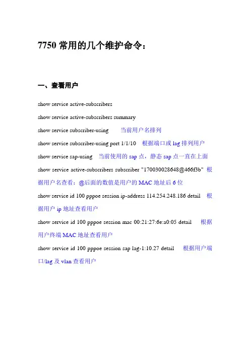
7750常用的几个维护命令:一、查看用户show service active-subscribersshow service active-subscribers summaryshow service subscriber-using 当前用户名排列show service subscriber-using port 1/1/10 根据端口或lag排列用户show service sap-using 当前使用的sap点,静态sap点一直在上面show service active-subscribers subscriber "170030028648@466f3b" 根据用户名查看:@后面的数值是用户的MAC地址后6位show service id 100 pppoe session ip-address 114.254.248.186 detail 根据用户ip地址查看用户show service id 100 pppoe session mac 00:21:27:6e:a0:05 detail 根据用户终端MAC地址查看用户show service id 100 pppoe session sap lag-1:10.27 detail 根据用户端口/lag及vlan查看用户二、清除用户下线clear service id 100 pppoe session sap-id 1/1/10:199.177 根据用户端口/lag及vlan清除用户clear service id 100 pppoe session ip-address 111.196.45.234 根据用户ip地址清除用户clear service id 100 pppoe session mac c8:0a:a9:dc:3f:35 根据用户终端MAC地址用户service id 值1为vprn,100为一般用户,8为与二层汇聚的互联三、查流量进入Monitormonitor# port 1/1/1 看端口流量monitor# lag 1 看LAG-1流量。

阿尔卡特7750SR路由器日常维护操作手册上海贝尔阿尔卡特股份有限公司互联网事业部二零零六年十月目录1. 总体概述................................................. 错误!未定义书签。
2. 常用软件操作............................................. 错误!未定义书签。
. 通过Console线缆连接路由器....................... 错误!未定义书签。
. SR系列路由器配置过程............................ 错误!未定义书签。
. 设备重启......................................... 错误!未定义书签。
. 路由引擎切换..................................... 错误!未定义书签。
. TiMOS软件升级步骤............................... 错误!未定义书签。
软件升级相关文件............................. 错误!未定义书签。
升级步骤..................................... 错误!未定义书签。
. 密码恢复......................................... 错误!未定义书签。
. 在CLI中获取帮助................................. 错误!未定义书签。
3. 7750SR-12 ................................................ 错误!未定义书签。
. 7750SR-12结构................................... 错误!未定义书签。
设备描述..................................... 错误!未定义书签。

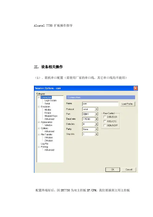
Alcatel 7750 扩板操作指导三.设备相关操作(1).联机串口配置(需使用厂家的串口线,其它串口线均不能用)配置终端好后,因SR7750为双主控板SF/CPM,我们要插到主用主控板上的console口,才能登入设备。
辨别主用主控板还是备用主控板时,我们需要看主控板上的CTL灯,显示为绿色常亮为主用主控板,显示是绿色闪烁的为备用主控板。
主控板CPM的其它灯的显示说明,请参照另一个文档设备的有没有插及插了多少块IOM板及MDA板,通过主控板上的灯是看不出来的,本身它就不具备此功能。
(2)在扩容之前,为安全起见我们需做设备配置的保存: admin save保存好后,需采集目前设备配置:admin display-config 多按几下回车键,才能采完(3)插板顺序,先插IOM板,再插MDA板(4)在插IOM板时一定要注意,主控板和IOM板上有保护胶套要先卸下才能插入槽位,否则板卡是插不位的, 无法加电。
如图:大卡为IOM卡,小卡为MDA卡(5)按设计的槽位插入IOM板卡,插入设备后,需用命令确认能否工作正常A:7750SR12# show card state/查看刚插好的IOM单板具体型号及槽位号,其中的槽位号是从设备面板上看出来的,也可以用此命令看。
我们刚插上的IOM板的型号及槽位号,在此命令下是有显示的,只是该板的admin state和oper state的状态没有达到UP。
确认IOM板命令如下:A:7750SR12#configure card X card-type XXX/具体板卡情况依实际情况定义第一个X代表设备是槽位号,XXX代表IOM的具体型号.这里就是要用到show card state显示的结果了。
确认IOM板卡后,稍等片刻,可以查看其是否工作正常了,命令如下:A:7750SR12#show card state/查看新插入IOM单板的运行状态,待新插入的IOM单板的admin state和oper state为UP状态后进入下一步操作。

课程4 实验–MPLS核心课程目标通过这些课程的学习,学员们将能够配置:•一个全网状MPLS 网络MPLS 配置如下实验保证一个IGP(OSPF,IS-IS)在网络中所有节点之间运行MPLS 节点 ____________1. 在路由器上启动MPLSSR# configure router mpls ↵SR>config>router>mpls$ exit ↵注:这个同样增加MPLS实例的系统接口SR>config>router>mpls$ info ↵SR>config>router>pls$ exit ↵2. 在网络接口上配置MPLS注: 启动MPLS在7750SR上运行,你必须增加至少一个网络接口到MPLS协议实例上。
当你在一个接口上启动MPLS,RSVP同时也启动了。
SR# configure router mpls interface <interface name> ↵SR>config>router>mpls>if$ exit ↵SR# configure router mpls interface <interface name> ↵SR>config>router>mpls>if$ exit ↵校核在路由器上已启动RSVPSR# show router rsvp status ↵SR# show router rsvp interface ↵3. 创建一个MPLS 通道为了设立一个LSP,你需要定义一个MPLS通道。
一个“通道”定义在7750SR的MPLS context之下,引用一列约束可以被应用到一个LSP将会跟随的通道。
对于网络图表对角的节点相反的路由器,配置一个严格的将会被LSP使用的MPLS 通道。
(使用一个IGP不会选择的通道)。
SR# config router mpls ↵SR>config>router>mpls# path <pathname>hop 1 <ipaddress> strict ↵SR>config>router>mpls>path$ no shutdown ↵SR>config>router>mpls>path$ exit ↵配置一个松散通道SR>config>router>mpls# path <pathname> ↵SR>config>router>mpls>path$ no shutdown ↵SR>config>router>mpls>path$ exit all ↵SR# show router mpls path ↵4. 配置MPLS LSP和主用通道注: 当已经建立了一个LSP,必须用命令“to”来指定输入路由器并至少指定一个主用一个主用通道或备用通道。
阿尔卡特7750培训资料9:VPRN第3章 7750 业务第9节 VPRN 业务7750 SR 业务设备 R3.0Alcatel University7750 SR 业务实现 R3.0VPRN 业务Alcatel Proprietary, all rights reserved ? 2005, AlcatelVPRN 业务Alcatel Proprietary, all rights reserved ? 2005, AlcatelSection 3 Module 9 Page 27750 SR 业务设备 R3.0Alcatel University本章目标成功的学完本章后,学员将会理解: ? ? ? ? ? ? VPRN 业务的操作和优点 7750 SR VPRN 实现 VPRN 拓扑 VPRN 操作包括路由区分符、路由目标、VRF 表、路由分配在 7750 SR 上进行 VPRN 配置 OAM 工具– VPRN ping and traceVPRN 业务Alcatel Proprietary, all rights reserved ? 2005, AlcatelSection 3 Module 9 Page 37750 SR 业务设备 R3.0Alcatel University虚拟专用路由网络VPRN 是VPN 的一类,它允许多个站点经过提供商管理的IP/MPLS 网络,在同一个路由域中连接RI-1 对所有的业务进行 MP-IBGP 路由交换CE BRI-1 RI-2PE BPE A 从客户的观点来看,好象RI-2 所有的站点都连接到一个路由域一样,在这个域中提供 CE A IP / MPLS 网络商PE的行为与其自己的路由器的行为相似。
业务提供商能重新使用 IP/MPLS 的基础设施来提供多种业务。
CE D 每个 VPRN 看起来都象一个额外的路由选择实例,通过使用MP-BGP(多协议边界网关协议)来交换在不同PE 间业务的路由。
上海贝尔阿尔卡特7750SR配置标准模板目录一、硬件配置 (5)1.1配置IOM卡 (5)1.1.1 查看已经插入的IOM卡的类型 (5)1.1.2 正确配置IOM卡的类型 (5)1.2配置MDA卡 (5)1.2.1 查看已经插入的MDA卡的类型 (5)1.2.2 正确配置MDA卡的类型 (5)1.3配置MDA端口 (6)1.3.1 POS端口配置 (6)1.3.2 以太口配置 (6)1.3.3 查看port信息 (6)二、设备管理配置 (8)2.1配置路由器名称、LOCA TION、CONTACT (8)2.2配置系统时间 (8)2.3配置SNTP (8)2.3.1 打开SNTP (8)2.3.2 配置SNTP地址 (8)2.4配置SR为TELNET服务器 (8)2.5.1 配置默认动作为允许,因为是所有上主控板的流量。
(9)2.5.2 配置允许IP段的ACL,配置源IP,协议,目的端口 (9)2.5.3 配置一条拒绝的ACL,拒绝其他IP段。
(9)2.6配置用户 (9)2.6.1 配置用户名 (9)2.6.2 配置用户密码 (9)2.6.3 配置用户登陆方式 (10)2.6.4 配置用户所属的组 (10)2.7配置LOG (10)2.7.1 配置log-id (10)2.7.2 配置log信息类型 (10)2.7.3 配置记录log的方式 (10)2.7.4 配置记录log方式的具体配置 (10)2.8配置SNMP (11)2.9配置主备板同步 (11)2.9.1 配置自动同步 (11)2.9.2 手工同步命令 (11)2.10配置空闲时间 (11)2.11配置ANTI-SPOOF (11)三、路由配置 (13)3.1配置路由器系统地址 (13)3.2配置网络接口 (13)3.2.1 配置interface名字及描述 (13)3.2.2 配置IP地址 (13)3.2.3 配置关联端口 (13)3.2.4 查看配置的路由器接口 (13)3.3配置静态及OSPF路由协议 (14)3.3.1 配置静态路由 (14)3.3.2 配置OSPF区域 (14)3.3.3 配置ospf接口cost值 (14)3.3.4 配置一个stub区域 (14)3.3.5 配置NSSA区域 (14)3.3.6 配置虚链路 (15)3.3.7 配置认证 (15)3.3.8 配置路由聚合 (15)3.3.9 配置静态路由注入到OSPF路由协议 (15)3.3.10 查看运行在ospf协议下的接口 (16)3.3.11 查看ospf邻居建立关系 (16)3.3.12 查看ospf路由表 (16)3.4配置IS-IS (16)3.4.1 配置区域ID (16)3.4.2 配置路由器等级能力 (17)3.4.4 查看ISIS下的接口 (17)3.4.5 添加已经配置到ISIS的每个网络接口 (17)3.4.6 查看ISIS邻接关系 (17)3.4.7 查看ISIS路由表 (17)3.5BGP配置 (18)3.5.1 创建AS (18)3.5.2 配置路由器 ID5 (18)3.5.3 配置 BGP (18)3.6配置POLICY (18)3.6.1 配置policy名称 (18)3.6.2 配置从静态路由分布到ospf路由协议中的policy (19)3.6.3 配置commit使之生效 (19)3.6.4 应用policy (19)3.7IP F ILTER配置 (19)3.7.1 创建ip filter (19)3.7.2 指定默认动作 (19)3. 7.3创建条目,指定动作、源、目的IP (19)3.7.4 应用ip filter (20)四、 MPLS 配置以及业务配置 (21)4.1MPLS配置 (21)4.1.1 MPLS接口配置 (21)4.1.2 创建已命名的MPLS路径 (21)4.1.3 配置 MPLS LSP和主路径 (21)4.1.4 查看命令 (22)4.1.5 改变每个网络接口的最大传输单元(MTU)尺寸 (22)4.2 E P IPE 配置 (22)4.2.1 创建客户并将其与提供的业务相关联 (22)4.2.2 指向客户的接口(在我们的网络中由膝上电脑表示)称为“toCustomer”,必须配置为接入接口。