林肯加油泵QSL401中文操作手册
- 格式:pdf
- 大小:2.09 MB
- 文档页数:26
MUL TI-SOURCEOPERATOR’S MANUALFor use with machines Code 10668October, 2000IM692Safety Depends on YouLinco ln arc welding equipment is designed and built with safety in mind. However, your overall safety can be increased by proper instal-latio n ... and tho ughtful o peratio n on your part.DO NOT INSTALL,OPERATE OR REPAIR THIS EQUIPMENT WITHOUT READ-ING THIS MANUAL AND THE SAFETY PRECAUTIONS CON-TAINED THROUGHOUT.And,most importantly, think before you act and be careful.Copyright © 2000 Lincoln Global Inc.This manual covers equipment which is nolonger in production by The Lincoln Electric Co. Speci cations and availability of optional features may have changed.Mar ‘95Mar ‘95Mar. ‘93for selecting a QUALITY product by Lincoln Electric. We want you to take pride in operating this Lincoln Electric Company product ••• as much pride as we have in bringing this product to you!Read this Operators Manual completely before attempting to use this equipment. Save this manual and keep it handy for quick reference. Pay particular attention to the safety instructions we have provided for your protection.The level of seriousness to be applied to each is explained below:vvOther indicator lights include the amber Thermal light that signals when the long term output current limit has been exceeded. This limit is determined by a ther-mostat sensing the temperature of the negative output lead from the secondary coils. The white Power light indicates when the Control board is energized. The three lights are high intensity LEDs for improved visi-bility in daylight.The Output Power display uses high intensity LEDs to indicate the percentage of full rated output the machine is supplying.Two additional thermostats protect the machine in the case of fan failure or blocked air flow. The SCR heat sink thermostat responds first to loss of air flow at nor-mal output loads. This thermostat will disable the machine output. The transformer iron rear thermostat senses that the lamination (and thus the coil insula-tion) is over heating (which can happen even if the output is disabled). This thermostat will interrupt power to the Control board causing the input contactor to open until the iron cools.The only user controls are an on-off toggle Power switch that energizes the machine and a 10 A circuit breaker protecting the fan auxiliary against short cir-cuits.DESIGN FEATURES - ALL MODELSSPECIFICATIONS,DESIG N FEATURES AND ADVANTAGESCase parts are predominantly stainless steel, the PC boards are potted in trays, the controls are sealed, all machine coils are copper and the whole transformer is varnish dipped to maximize environmental withstand capability. The coils are all conservatively rated for long life.The Multi-Source output regulates against wide changes in output loading and input line voltage varia-tions to supply a consistently stable voltage high enough to allow the Multi-Welds to provide good man-ual electrode capability.SAFETY PRECAUTIONSGENERAL DESCRIPTIONThe Multi-Source is designed to supply power to the Multi-Weld welders. It has a wide range three phase AC input and can be operated on 50 or 60 Hz. The Multi-Source output peak voltage regulates against wide changes in output loading and input line voltage variations to supply a consistently stable voltage high enough to allow the Multi-Welds to provide good man-ual electrode capability.Primary input voltage taps are selected by a single movable link on the reconnect panel. Main trans-former auxiliary windings power the firing circuit and fan motor. The control auxiliary transformer has a sin-gle, wide range primary and is not reconnectable.The Fan As Needed feature is activated by an output current of 20 Adc or a thermostat on the main trans-former iron.An independent safety circuit on the Control board monitors the voltage peaks and opens the input con-tactor if the limit is exceeded. The green Safe Output light indicates when the machine output voltage isFACTORY INSTALLED OPTIONS / ACCESSORIESThere are no factory installed options.FIELD INSTALLED OPTIONS / ACCESSORIESK1735-1 Multi-Weld 350, Multi-process controller.K857, K857-1 Remote Control, Control Multi-Weldremotely (25 or 100 ft.).K1736-1 Distribution Box, Connects up to 10 Multi-Welds.K449 LN-25, Across the arc wire feeder.K1788-1 Roll Cage, Protect power source, facilitate moving, store cable.K1806-1 Multi-Weld Four Pack, Mounting / lift rack for M-S and four M-Ws.K1807-1 Multi-Weld Eight Pack, Mounting / lift rack for M-S and eight M-Ws.S20428Paralleling Kit,Allows two machines toequally share double load.MACHINE CALIBRATION SPECIFICATIONThe Multi-Source digital display is controlled by a cur-rent sensing circuit on the Control board. The display reads 100 when machine output is a little over 40 kW. To recalibrate the display, the machine output may loaded with Multi-Weld welders or resistive grids or a combination of both to obtain an output of 533 Adc as read by a calibrated standard ammeter. Trimmer resistor R49 may be adjusted to cause the display to read 100.This Troubleshooting Guide is provided to help you locate and repair possible machine malfunctions.Simply follow the three-step procedure listed below.Step 1.LOCATE PROBLEM (SYMPTOM).Look under the column labeled “PROBLEM (SYMP-TOMS)”. This column describes possible symptoms that the machine may exhibit. Find the listing that best describes the symptom that the machine is exhibiting.Step 2.POSSIBLE CAUSE.The second column labeled “POSSIBLE CAUSE” liststhe obvious external possibilities that may contribute to the machine symptom.Step 3.RECOMMENDED COURSE OF ACTIONThis column provides a course of action for the Possible Cause, generally it states to contact your local Lincoln Authorized Field Service Facility.If you do not understand or are unable to perform the Recommended Course of Action safely, contact your local Lincoln Authorized Field Service Facility.HOW TO USE TROUBLESHOOTING GUIDEService and Repair should only be performed by Lincoln Electric Factory Trained Personnel.Unauthorized repairs performed on this equipment may result in danger to the technician and machine operator and will invalidate your factory warranty. For your safety and to avoid Electrical Shock, please observe all safety notes and precautions detailed throughout this manual.__________________________________________________________________________5. LEDs 1 through 6 indicate gate signals are being sent to the main SCRs 1 through 6 respectively. If LED2 on the Control board is bright, along with LEDs 7, 8, and 9 on Firing board, and LEDs 1through 6 are unequal in brightness, check to make sure lead 231 between Control board and Firing board is not broken. (If lead 231 is removed while the machine output is at open circuit, the output voltage peaks may be unregulated and cause the over-voltage protection circuit to open the input contactor. The over-voltage protection circuit may disabled by disconnecting lead 222D at the nega-tive output stud or at pin 1 of P2. NOTE: Themachine may not be used for welding with the pro-tection circuit disabled.6. If one or more of LEDs 1 through 6 are off, LEDs 7,8, and 9 are on and the voltage on lead 231 from the Control board (pin 13, P5 to pin 12, P5) is 3 to 13Vdc replace the Firing PCB.PC BOARD TROUBLESHOOTING GUIDE - FIRING P .C.BOARD1. LEDs 1 through 9 must be lit when the Multi-Source is turned on and the Control board is sending an enable signal to the Firing board (pin 7 in P8 is low in reference to common at pin 12 in P5).2. LEDs 7, 8, and 9 indicate AC power being supplied to the P.C. board from auxiliary windings on the main transformer (T1). If a LED is not on, turn the machine off and unplug P8 from the firing board.Turn the machine back on and check the following voltages:3. If all voltages are present, turn power off, and plug P5 back into J5. Turn power back on. If LEDs 7, 8or 9 are still not lit, replace Firing PCB.4. If voltages were not present, check the circuit back through the external dropping resistors to the auxil-iary windings for a possible open resistor or wire.PC BOARD TROUBLESHOOTING GUIDE - CONTROL P .C.BOARD1. The white Power light on the machine control panel indicates that the Control board power supply is being supplied by rectified secondary voltage from the Control transformer (T2) by way of the Power switch and transformer iron rear thermostat.2. LED1 indicates machine output voltage. At normal output voltages, LED1 will be brightly lit.3. LED2 indicates the level of the control signal to the Firing board. The brightness of LED2 is inversely proportional to machine output because the control signal increases as the machine output decreases.4. LED3 lights when the current amplifier senses an output current over about 10 amps and sends a sig-nal to turn the cooling fan on. If LED3 is on but the fan is not , there could be a problem with the fan motor or the fan motor drive circuit (see LED6).5. LED4 says that some signal, either thermostat, out-put current or output over-current is calling for the fan to operate.6. LED5 tells us that the current signal from the shunt is too high. If LED5 is lit for 5-8 seconds, the enable signal to the Firing board is made high to shut off the output SCRs. In the case of a short duration current overload, LED5 may only be briefly litbecause, in normal operation, the machine output immediately goes to zero. Once disabled, the out-put will remain off for about 75 seconds.7. LED6 indicates that the input to the fan motor opto triac driver has been energized. LED6 should be on as long as the fan motor runs. LED6 and the fan motor will be on for about 5 minutes after LED4goes off.8. LED7 will light when the shorted SCR circuit acti-vates. A positive voltage on the negative output stud (AC instead of DC on the output studs) will activate a circuit causing the input contactor to open. This circuit is active only when the enable signal to the Firing board is high (the output is off).The contactor will remain open (and the whitePower light will remain on) until the Power switch is turned off (or the input power to the machine is oth-erwise removed) for about 1 second and then turned on again.9. The green Safe Output light on the control panel when the machine output voltage is present and safe. It lights when the machine output is between 40 Vdc and 113 volts peak. 10. The yellow Thermal light on the front panel lightswhen the open thermostat signal is sent to the fan control and output disable circuits.Now Available...12th EditionThe Procedure Handbook of Arc WeldingWith over 500,000 copies of previous editions published since 1933, the Procedure Handbook is considered by many to be the “Bible” of the arc welding industry.This printing will go fast so don’t delay. Place your order now using the coupon below.The hardbound book contains over 750 pages of welding information, techniques and procedures. Much of this material has never been included in any other book.A must for all welders, supervisors, engineers and designers. Many welding instructors will want to use the book as a reference for all students by taking advantage of the low quantity discount prices which include shipping by 4th class parcel post.$15.00postage paid U.S.A. MainlandHow To Read Shop DrawingsThe book contains the latest information and application data on the American Welding Society Standard Welding Symbols. D etailed discussion tells how engineers and draftsmen use the “short-cut” language of symbols to pass on assembly and welding information to shop personnel.Practical exercises and examples develop the reader’s ability to visualize mechanically drawn objects as they will appear in their assembled form.187 pages with more than 100 illustrations. Size 8-1/2” x 11”Durable, cloth-covered board binding.$4.50postage paid U.S.A. MainlandNew Lessons in Arc WeldingLessons, simply written, cover manipulatory techniques;machine and electrode characteristics; related subjects,such as distortion; and supplemental information on arc welding applications, speeds and costs. Practice materials,exercises, questions and answers are suggested for each lesson.528 pages, well illustrated, 6” x 9” size, bound in simulated,gold embossed leather.$5.00postage paid U.S.A. MainlandNeed Welding Training?The Lincoln Electric Company operates the oldest and most respected Arc Welding School in the United States at its corporate headquarters in Cleveland, Ohio. Over 100,000stu-dents have graduated. Tuition is low and the training is “hands on”For details write:Lincoln Welding School 22801 St. Clair Ave.Cleveland, Ohio 44117-1199.and ask for bulletin ED-80 or call 216-383-2259 and ask for the Welding School Registrar.Lincoln Welding SchoolBASIC COURSE $700.005 weeks of fundamentalsThere is a 10%discount on all orders of $50.00 or more for shipment at one time to one location.Orders of $50 or less before discount or orders outside of North America must be prepaid with charge, check or money order in U.S. Funds Only.Prices include shipment by 4th Class Book Rate for U.S.A. Mainland Only.Please allow up to 4 weeks for delivery.UPS Shipping for North America Only.All prepaid orders that request UPS shipment please add:$5.00For order value up to $49.99$10.00For order value between $50.00 & $99.99$15.00For order value between $100.00 & $149.00For North America invoiced orders over $50.00 & credit card orders, if UPS is requested, it will be invoiced or charged to you at cost.Outside U.S.A. Mainland order must be prepaid in U.S. Funds. Please add $2.00 per book for surface mail or $15.00 per book for air parcel post shipment.METHOD OF PAYMENT:(Sorry, No C.O.D. Orders)CHECK ONE:Name:_______________________________________________Please Invoice (only if order is over $50.00)Address:_______________________________________________Check or Money Order Enclosed, U.S. Funds only _______________________________________________Credit Card - Telephone:_______________________________________________Signature as it appears on Charge Card:Account No.Exp Date|_|_||_|_|______________________Month YearUSE THIS FORM TO ORDER:Order from:BOOK DIVISION, The Lincoln Electric Company, 22801 St. Clair Avenue, Cleveland, Ohio 44117-1199BOOKS OR FREE INFORMATIVE CATALOGS Telephone: 216-383-2211 or, for fastest service, FAX this completed form to: 216-361-5901.Lincoln Welding School Titles:Price Code QuantityCost(ED-80)New Lessons in Arc Welding $5.00L Seminar Information Procedure Handbook “Twelfth Edition”$15.00PH (ED-45)How to Read Shop Drawings $4.50H Educational Video Information Incentive Management $5.00IM (ED-93) A New Approach to Industrial Economics $5.00NA James F. Lincoln Arc Welding The American Century of John C. Lincoln $5.00AC Foundation Book Information Welding Preheat Calculator $3.00WC-8(JFLF-515)Pipe Welding Charts $4.50ED-89SUB TOTALAdditional Shipping Costs if anyJapaneseChineseKoreanArabicREAD AND UNDERSTAND THE MANUFACTURER’S INSTRUCTION FOR THIS EQUIPMENT AND THE CONSUMABLES TO BE USED AND FOLLOW YOUR EMPLOYER’S SAFETY PRACTICES.SE RECOMIENDA LEER Y ENTENDER LAS INSTRUCCIONES DEL FABRICANTE PARA EL USO DE ESTE EQUIPO Y LOS CONSUMIBLES QUE VA A UTILIZAR, SIGA LAS MEDIDAS DE SEGURIDAD DE SU SUPERVISOR.LISEZ ET COMPRENEZ LES INSTRUCTIONS DU FABRICANT EN CE QUI REGARDE CET EQUIPMENT ET LES PRODUITS A ETRE EMPLOYES ET SUIVEZ LES PROCEDURES DE SECURITE DE VOTRE EMPLOYEUR.LESEN SIE UND BEFOLGEN SIE DIE BETRIEBSANLEITUNG DER ANLAGE UND DEN ELEKTRODENEINSATZ DES HER-STELLERS. DIE UNFALLVERHÜTUNGSVORSCHRIFTEN DES ARBEITGEBERS SIND EBENFALLS ZU BEACHTEN.JapaneseChineseKoreanArabicLEIA E COMPREENDA AS INSTRUÇÕES DO FABRICANTE PARA ESTE EQUIPAMENTO E AS PARTES DE USO, E SIGA AS PRÁTICAS DE SEGURANÇA DO EMPREGADOR.。
汽油机水泵使用说明一、安全规定1.使用前,务必在曲轴箱内加入指定机油。
2.发动机运转时严禁加注汽油。
3.消声器排气口附近禁止放置易燃品。
4.本机应放置于平坦场所使用。
5.使用前务必往泵体内加入足够的水。
水泵中剩余的水温度高,有烫伤的危险,请注意。
6.操作水泵前水泵抽水末端务必安装过滤器,防止异物进入堵塞或损坏水泵内部件。
7.水泵禁止抽吸泥浆水、废弃机油、酒类等物质。
8.注意在抽沼气管路井室的水时,注意检测毒气,防止爆炸危险。
二、启动准备(一)、启动前检查汽油机1.汽油机润滑油油位检查在没有足够润滑油的情况下运行,将会引起汽油机的严重损坏。
检查汽油机时,要使其停止运行并处于水平平面上。
(1)卸下润滑油加入口盖,擦干油尺。
(2)把油尺插入加油口,但不要拧旋它。
(3)如果油位低,加入推荐使用的润滑油直到机器厂家推荐油尺位置。
推荐机油:四冲程汽油机机油API分类的SE.SF或相当于SG级的(SAE10W-30)机油。
低温时,(气温在10℃以下)推荐使用SAE10W-30机油,寒冷时(气温在-15℃)以下请使用API分类的SE.SF或者相当于SG级的SAE10E-30机油。
SAE10E-30是被推荐使用的通用润滑油,它适合一般环境温度。
如果使用但粘稠度的润滑油,应选择与使用的平均温度相对应的粘稠度。
使用无清洁剂的润滑油或者二冲程润滑油,将缩短汽油机的寿命。
2.空气滤清器检查●绝对不要在无空气滤清器时运转汽油机,不然会加速汽油机的磨损。
●检查滤芯上的灰尘和杂物。
3.加注燃油使用汽车用的汽油,最好使用无铅或者低铅汽油,这样可减少燃烧室内的沉积。
决不要使用机油/汽油混合油或者脏汽油,避免燃油箱内掉进灰尘、垃圾及水。
警告!汽油非常易燃,在一定条件下会发生燃烧爆炸。
在通风良好的地方加油,加油时汽油机要停止运转,在加油地不能抽烟,存储汽油地严禁明火及火花。
油箱不要加的过满(加油口颈部应无燃油),加完油后,检查油箱盖是否盖好。
加油泵威科安全操作及保养规程加油泵威科是一种常见的加油设备,被广泛用于油站、加油点和一些工业企业中。
它可以方便、快速地将燃油输送到车辆或机器设备中,并且具有一定的自动化控制功能。
但是,使用加油泵威科时也存在一定的安全风险。
因此,本文将为大家介绍加油泵威科的安全操作规程及保养方法,以确保操作人员的安全和设备的正常运行。
安全操作规程1.负责人员要求在使用加油泵威科时,必须由专人负责操作、监督和维护设备。
操作人员必须是经过专业培训并合格认证的人员,且必须全程保持专注和稳定心态。
2.可靠的电源供应加油泵威科的电源供应必须可靠,并且符合国家相关的标准和规定。
当电源供应出现异常时,必须立即停止使用设备,并及时检查、修复。
3.保证设备残留产品溢出量控制在加油泵威科进行加油过程中,必须严格控制设备的残留产品溢出量。
操作人员要根据所需加油数量合理控制加油时间、加油速度和加油量,避免因过量加油而导致燃油溢出。
4.防止火源加油泵威科的加油区域是易燃易爆区域,应做好火源防护工作。
在操作设备前,应检查加油区域内是否存在明火、电火花、静电等可能引起火灾的隐患,并采取相应的防护措施。
5.防爆电器设备要求在加油泵威科所在的场所需要防爆电器设备,以防止因电器设备引起的火灾。
6.安全装置的控制要求加油泵威科必须配备可靠的安全保护装置,比如泄漏检测、超温报警等系统,在使用前必须检查是否正常工作。
在操作设备过程中,操作人员应保持警惕,及时处理出现的报警信息。
7.停机须知在停机前,必须先将加油泵威科内的燃油泵内压力卸掉。
且在操作结束后及时对设备进行清洁保养,保持设备状态良好。
保养方法1.经常检查设备使用加油泵威科之前,应先对设备进行检查。
检查内容包括:电源、油门、表头、机油、检漏、防爆设备、安全设备、控制面板、配套油管等。
同时,设备也需要定期检修,更换磨损的零配件,保持整个设备的正常运转。
2.定期清洗设备加油泵威科应经常清洗设备,保持其干净卫生。
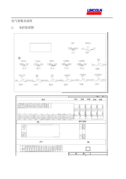
电气参数及说明1.电控原理图2.接线图1).所有传感器必须是PNP型.如果为两线,则接信号线(004,005,006)和24V,查看传感器接线说明,分清那根为24V线(一般为棕线),另一根线则接信号线(004,005,006);如果为三线请根据传感器说明书接线.{常规接法为,棕线为24V,兰线为COM,黑线为信号线(004,005,006).}注意系统运行过程中,如果按试灯按钮,需重新按下自动或手动按钮,系统才能够恢复运行状态.3.参数说明代号内容说明单位推荐值T1 自动运行时间. 小时/分钟 60分钟T2 自动运行休息时间小时/分钟 30分钟T3 计量泵1,计量泵2延时打开的时间分钟/秒 30秒T4 计量泵1,计量泵2延时关闭的时间分钟/秒 30秒T5 计量泵1,计量泵2工作时间分钟/秒5秒T6 计量泵1,计量泵2关闭时间分钟/秒 10秒T7 计量泵1工况监控时间分钟/秒 30秒T8 计量泵2工况监控时间分钟/秒 30秒C1 计量泵1工况监控次数次 2C2 计量泵2工况监控次数次 2 注:以上推荐值只起参考作用,系统具体设定值应以系统使用实际情况设置。
4.参数设定步骤a. 下列图示为开机状态下显示屏的原始状态:b. 按“OK”键进入菜单:c. 按 “DOWN”键选择( PARAMETER)子菜单d. 按 “OK”键进入调整菜单:运行时间e. 按“UP”键或“DOWN”键进行时间选项(T1,T2,T3,T4,T5,);按“OK”键进入。
f. 按 “LEFT” 键进入时间,按“LEFT”键或“RIGHT”键进行选择;按 “UP”键或 “DOWN”键进行调整.调整好后按 “OK” 键进行保存,然后按ESC键退出。
五.操作说明及使用注意事项操作部鄹:1),对油路/气路管道进行酸洗,保证管道清洁;2),给油池内加注满润滑油;3),检查所有油路/气路截止阀,使其处于开位;4),松开气动计量泵1/气动计量泵2油路进口接头;5),接通总气源,将气动二联件1气压调至8bar;6),调节气动二联件4,将气压调至3-4bar(此时气动油脂泵开始往气动计量泵补油);7),当松开气动计量泵油路进口接头开始出油的情况下,逐一拧紧;8),接通总电源,拔起急停开关(电源指示灯亮起);9),设置PLC各项参数,首次使用时应将时间参数T7/T8设置得长一些,设置方法见第15页;10),将手动/自动转换开关拨至手动档,按下手动运行按钮(手动运行指示灯亮起);11),节气动二联件/3、气动二联件/4将气压调至7bar;12),调节减压阀/1、减压阀/2将气压调至4bar;13),调节左右喷射面板喷嘴喷射角度至合适位置;14),系统正常喷油后,设置PLC各项参数至正常,设置方法见第15页;15),将手动/自动转换开关拨至自动档,按下自动运行按钮(自动运行指示灯亮起),系统正常运行。
林肯加脂机说明书一、注意事项1.将林肯加脂机气泵左侧的操作板踩下,继续上下操作手柄,注意观察小压力表的数值,等到压力上升至600-800kpa时停止操作手柄。
2.将林肯加脂机上的注脂接头连接到阀门的注脂嘴上,用脚缓慢踩下林肯加脂机气泵上面右侧的操作板,即开始注脂,注意观察注脂时的压力变化,注脂压力不要超过6000psi。
3.等听到注脂声音有明显变化且看到注脂压力立即下降时,表示一次注脂完成,注脂量大约为16盎司。
注脂时间大约需要1分钟。
如需要继续注脂请重复第6部。
4.等千斤顶上升至最大限度时,将千斤顶泄压并把托盘下部的支撑杆推至托盘正下方,然后继续上下操作手柄即可。
5.等千斤顶再次上升至最大限度时,表示筒中的脂已用完需要更换。
6.如需更换注脂筒请重复第4第5步。
二、林肯加脂机的检查、维护及保养1.林肯加脂机的检查2.林肯加脂机每季度应进行检查和维护3.检查林肯加脂机储油罐的油位,油位应保持在距离罐口1厘米处,液压油缺乏时应及时补充,安装丝堵,用手拧紧。
4.5.检查并确保所有的气路和油路的连接处无松动、泄漏。
6.林肯加脂机每操作100小时应更换液压油,在使用条件恶劣时缩短更换液压油的时间间隔。
7.在气动马达上装有过载泄压阀,已预调到最大操作压力,禁止调试过载泄压阀。
8.检查林肯加脂机再运行时是否可以建立注入压力,如无法建立注入压力,那么:1)确认液压油满足要求。
2)将气动林肯加脂机水平放置。
3)将气源压力调节到30~40PSI〔2.1~2.7bar〕。
4)将林肯加脂机踏板向前储油罐方向置于卸载的位置。
5)压下踏板后端下方的按钮启动启动马达,马上向前储油罐6)方向压下踏板几次,使油流回到泵中并充满整个通道。
7)检查泵是否可以加载,正常操作。
如不能那么重复第5 步。
9.林肯加脂机的存放1)林肯加脂机存放前应擦拭干净。
2)林肯加脂机载存放时应撤除所有的空气和液体的连接管路。
3)林肯加脂机应储存于枯燥、清洁的环境中,不应放置于温度过高或过低的地方。
林肯泵资料1.泵装臵1.1综述:KFG 、KFGS 型系列泵装臵适用于车辆、机床及工程机械等的摩擦副的润滑,其适用的润滑剂为000#、00#、0#、1#及2#润滑脂。
每套泵装臵可同时安装一到三套泵单元,组成一至三个润滑回路。
KFG 、KFGS 型泵装臵的固定:利用3只M8的螺栓固定于主机设备上;所用固定螺栓须自备或按订货号951 130 115订购。
泵装臵的应尽可能的安装于不易受外界侵扰或损坏的适当位臵,设备上的安装孔应按右图所示钻取。
图1 安装孔尺寸1.2 装臵外形参数:1.3 泵单元:KFG泵装臵设有3个润滑输出口,可同时安装一到三套泵单元;每组泵单元均可与递进式分配器连接组成独立的润滑油路.当3个润滑输出口未能全部使用时,富余的输出口可用以下件封堵: 螺堵M20X1.5垫圈20泵单元外形及连接尺寸如右图所示.图3 泵单元图4 KFG1.U2 1.4KFG1.40可调型泵单元:给脂量调整表格:单位: ml/min圈数给脂量调整方法:1.用内六角扳手卸下内六角螺堵6;2.用内六角扳手调整内六角螺丝8:顺时针方向旋转—调小给脂量;逆时针方向旋转—调大给脂量。
3.3圈=6个单位调节量1圈= 1mm =2个单位调节量4. 调整合适后,固紧内六角螺堵6。
1.5 溢流阀:单独的溢流阀直接安装于泵单元出口,保护整个润滑系统免受过高的压力。
溢流阀的调整压力为300bar。
如系统中递进式分配器或润滑点发生堵塞,导致系统压力高于300bar,则溢流阀自动开启卸油。
溢流阀规格:A-------接φ6管P--------接泵单元A-------接φ10管R--------溢脂口1.6润滑脂要求:VOGEL 要求使用1号或2号锂基脂,及国际标准≤NLGI grade2,最好采用进口油脂,严禁采用3号油脂,因为3号以上属于超硬油脂。
在加油时一定注意油脂的清洁度,防止污物颗粒阻塞分配器。
1.7 充填润滑脂:KFG 型泵装臵的脂罐润滑脂充填可采用如下几种方式:锥形脂咀:利用普通的加脂枪通过泵装臵本体上的锥形脂咀充填润滑脂。
第1篇一、目的为确保小型汽油泵的正常运行,保障加油站的安全生产,防止火灾、爆炸事故的发生,特制定本规程。
二、适用范围本规程适用于加油站内所有小型汽油泵的操作。
三、操作前的准备1. 操作人员必须经过专业培训,熟悉汽油泵的操作规程,取得相关资格证书。
2. 检查汽油泵外观是否完好,电气线路是否正常,确保设备安全可靠。
3. 检查加油枪、油枪座、油罐车连接管等配件是否完好,无泄漏现象。
4. 确认汽油泵电源开关处于关闭状态,确保操作安全。
5. 检查消防器材是否齐全、有效,确保应急处理能力。
四、操作步骤1. 打开电源开关,启动汽油泵。
2. 将加油枪插入油罐车连接管,确保连接牢固。
3. 调整加油枪,使其对准油罐车油箱口。
4. 打开油罐车油箱盖,确保油箱内无空气,防止产生静电。
5. 调整加油枪流量,控制加油速度,避免过快加油引发火灾。
6. 观察加油枪加油过程中有无异常情况,如汽油喷溅、泄漏等。
7. 加油过程中,严禁触摸加油枪、油枪座等部位,防止静电引发火灾。
8. 加油完毕后,关闭加油枪,将加油枪插入油罐车连接管,关闭油罐车油箱盖。
9. 关闭汽油泵电源开关,切断电源。
五、操作后的检查1. 检查加油枪、油枪座、油罐车连接管等配件是否完好,无泄漏现象。
2. 检查汽油泵外观是否完好,电气线路是否正常。
3. 检查消防器材是否齐全、有效。
4. 填写加油记录,包括加油时间、加油量、车辆信息等。
六、注意事项1. 操作人员必须佩戴防静电手套、防静电鞋等防护用品。
2. 操作过程中,严禁吸烟、打火机等火源靠近汽油泵。
3. 如遇汽油泄漏,立即关闭汽油泵,切断电源,开启应急通风,通知相关人员处理。
4. 加油过程中,严禁在油罐车旁停留、嬉戏,确保安全。
5. 操作人员应熟悉本规程,严格遵守各项安全操作规定。
六、附则1. 本规程由加油站安全管理部门负责解释。
2. 本规程自发布之日起实施。
第2篇一、适用范围本规程适用于本公司所有小型汽油泵的操作人员,以确保汽油泵的安全、高效运行,防止火灾、爆炸等安全事故的发生。

1、2号机组燃油泵启、停操作指导书编写:韩磊批准:淮浙煤电凤台电厂运行部2007年12月7日燃油泵运行1燃油泵的启动和停止1.1燃油泵启动前的检查。
1.1.1检查检修工作结束,各设备人孔门关闭、地脚螺栓固定完好,转动机械的防护罩已罩好,管道及其连接良好,支吊架牢固。
设备及管道的保温完整,现场整洁,道路畅通,楼梯、平台、栏杆完好,照明充足,安措恢复,工作票终结。
1.1.2检查热工表计、信号、联锁保护齐全,开启各仪表一次阀。
1.1.3系统各阀门应操作开关灵活,反馈显示与实际位置相对应。
1.1.4检查转动机械轴承和各润滑部件,油位正常,油质合格,润滑油脂已加好。
1.1.5燃油泵轴承冷却水投入正常。
1.1.6对可盘动的转动机械,应手盘靠背轮,确认转动灵活无卡涩现象。
电动机检修后的初次启动,必须经单独试转合格方可连接。
1.1.7对系统进行全面检查,按《燃油泵系统阀门检查卡》的要求将各阀门置于正确位置。
1.1.8检查各水箱、油箱液位正常,水质或油质合格,油箱应放尽底部积水,并做好系统设备的充水(油)放气工作。
1.1.9电动机接线和外壳接地线良好,且按规定测量绝缘合格。
1.1.10相应系统的其他检查工作结束后,送上燃油系统各设备的动力电源、控制电源,有关保护投入。
1.1.11配合热工、电气完成辅机的各联锁、保护试验工作,且应动作正常、定值正确(注意:6kV电动机的联动试验,应先联系电气将开关置于“试验”位置后再进行,试验结束后再送电)。
1.1.12机组正常运行中的设备检修后恢复,应按要求进行试运检查,确认正常后,方可投入运行或备用方式。
1.1.13设备及系统的操作须作好详细记录,重要操作应执行操作监护制度。
1.1.14油泵进口滤网清洗好,放油阀、吹扫阀关闭。
1.1.15油罐油位在2米以上。
1.2燃油泵的启停。
1.2.1燃油泵启动。
1.2.1.1确认供油系统各阀门开、关位置正确,炉前油系统阀门位置正确。
1.2.1.2启动一台燃油泵,开启出口阀,检查运行正常,投入备用泵联锁。
油泵操作规程1. 引言本文档旨在规范油泵的操作流程,以确保设备的安全操作和有效运行。
所有操作人员应严格遵守本规程,并按照操作步骤进行操作。
2. 操作流程2.1. 准备工作在进行油泵操作之前,操作人员应完成以下准备工作:1.检查工作环境是否安全,清理工作区域,确保没有杂物堆积、易燃物等危险物品;2.检查电源线是否连接良好,并确保接地良好;3.根据需要,检查油泵是否添加足够的润滑油或液压油。
2.2. 启动油泵按照以下步骤启动油泵:1.打开油泵电源开关,确保电源正常供应;2.按下油泵启动按钮,启动油泵;3.检查油泵运行状况,确保油泵无异常声响和振动。
2.3. 检查油压在油泵启动后,操作人员应检查油压是否正常。
步骤如下:1.调节油泵压力开关至所需压力值;2.观察油泵压力表,确保油压稳定在所需范围内。
2.4. 操作油泵根据需要,进行相应的油泵操作。
例如:1.若需向目标设备提供润滑油,将油泵的出口连接到设备的润滑系统,并确保连接牢固;2.根据需要,调节油泵流量调节阀,控制润滑油的流量;3.监控润滑系统的压力情况,确保润滑油进入设备的压力适宜。
2.5. 停止油泵在完成油泵操作后,应按照以下步骤停止油泵:1.关闭油泵电源开关,断开电源供应;2.等待油泵停止运行,并确保油泵完全停止后方可进行下一步操作。
2.6. 清洁和维护在停止油泵后,操作人员应进行清洁和维护工作:1.关闭油泵的阀门和流量调节阀,并清洁它们的表面;2.清洁油泵表面,去除附着的油污和杂物;3.定期检查油泵的各个部件,确保它们的正常运行;4.如有异常现象或故障,请立即向维护人员报告。
3. 安全注意事项在操作油泵时,务必注意以下安全事项:1.操作人员应熟悉油泵的结构和工作原理,并在操作前接受相关培训;2.使用油泵时,应佩戴个人防护装备,如手套、护目镜等;3.禁止将手部或其他身体部位放入运行中的油泵内部;4.在操作过程中,若发现油泵运行异常、有异常声响或振动,应立即停止使用,并通知维护人员;5.禁止非专业人员进行油泵的拆卸和维修。

OIL DISPENSING SYSTEMOWNER’S MANUALItem#20108 Item#34007serious personal injury.Thank you very much for choosing a Roughneck™ Product! For future reference, please complete the owner’s record below:Model: _______________ Purchase Date: _______________Save the receipt, warranty and these instructions. It is important that you read the entire manual to become familiar with this product before you begin using it.This machine is designed for certain applications only. The distributor cannot be responsible for issues arising from modification. We strongly recommend this machine is not modified and/or used for any application other than that for which it was designed. If you have any questions relative to a particular application, DO NOT use the machine until you have first contacted distributor to determine if it can or should be performed on the product.For technical questions, please call 1-800-222-5381.WARNING: Read carefully and understand all INSTRUCTIONS before operating. Failure to follow the safety rules and other basic safety precautions may result in serious personal injury.SAVE THESE INSTRUCTIONSPump: Electric self-priming rotary internal gear pump, equipped with a bypass valveMotor: Asynchronous motor, 4-pole, closed type (Protection class IP55), self-ventilating, flange-mounted directly to the pump body.Both systems are designed to run on 115V, 60Hz power and for use with high-viscosity oils and lubricants from a drum anywhere in your shop.Model 20108 34007PUMPVoltage 115 Volts 115 VoltsFrequency 60Hz 60HzPower 900 Watts 1500 WattsFlow Rate 18 quarts/min. (4.5 GPM) 52 quarts/min. (13 GPM)Pressure 175 PSI 145 PSIInlet/Outlet 1in. 1in.Oil Viscosity Up to 10,000 SUS Up to 10,000 SUSDelivery Hose 1/2in.x13ft. 3/4in.x13ft.CONTROL VALVEFlow rate range 0.3–9.2 GPM 0.3–16 GPMPressure range 7–750 PSI 7–750 PSIWorking Temperature Max. 140°F Max. 140°FAccuracy ±0.5%±0.5%Viscosity of Fluid 8-5000 mPas 8-5000 mPas5-Digit LCD display Liter, Quarts, Pints, Gallons Liter, Quarts, Pints, GallonsInlet connection 1/2in. NPT Female 1/2in. NPT FemaleSpout Rigid, Manual tip Rigid, Automatic tipPower source (1) 3V CR2 battery (1) 3V CR2 batteryCart Capacity 484 lbs. 484 lbs.NOTE: The power absorbed by the pump depends on the functioning point and the viscosity of the oil being pumped.Installation DimensionWARNING: Read and understand all instructions.WARNING: The warnings, cautions, and instructions discussed in this instruction manualcannot cover all possible conditions or situations that could occur. It must be understood by the operator that common sense and caution are factors that cannot be built into this product, but must be supplied by the operator.1. Keep the work area clean and dry. Damp or wet work areas can result in injury.2. Keep children away from work area. Do not allow children to handle this product.3. Store idle equipment. When not in use, tools and equipment should be stored in a dry location to inhibit rust. Always lock up tools and equipment, and keep out of reach of children.Pump for #20108Pump for #340074. Use the right tool for the job. Do not attempt to force small equipment to do the work of largerindustrial equipment. There are certain applications for which this equipment was designed. It will do the job better and more safely at the capacity for which it was intended. Do not modify this equipment, and do not use this equipment for a purpose for which it was not intended.5. Check for damaged parts. Before using this product, carefully check that it will operate properly andperform its intended function. Check for damaged parts and any other conditions that may affect the operation of this product. Replace damaged or worn parts immediately.6. Do not overreach. Keep proper footing and balance at all times to prevent tripping, falling, back injury,etc.7. DO NOT use the equipment when tired or under the influence of drugs, alcohol, or medication.A moment of inattention while operating this equipment may result in serious personal injury.8. Industrial applications must follow OSHA requirements.DANGERElectrical shock hazard.Electrical wiring should be done by a licensed electrician incompliance with local, state and national electrical code,ANSI/NFPA 70, 30, 30A as appropriate.Proper ground must be provided to avoid the possibility ofelectrical shock. Failure to comply with this warning couldresult in serious injury and/or loss of property.WARNING: Improper use or installation of this product can cause serious bodily injury or death.NOT FOR USE WITH LIQUIDS AS GASOLINE, ALCOHOL, EXPLOSIVES, CORROSIVES AND FLAMMABLE, ALIMENTARY LIQUIDS.Do not use the unit in an explosive environment.Do not use the unit next to flammable liquids (gasoline, alcohol, etc.).Do not use the unit in closed environments in presence of gasoline, LPG, methane fuelled vehicles.Always wear suitable clothes and use suitable protective devices when cleaning, especially when removing dust or waste. Use aspirators as needed.Never place hands or limbs under moving parts.Disconnect power to pump before servicing pump.NEVER overload.1. ENVIRONMENTAL CONDITIONSTemperature:Min 14°F (-10°C) / Max +140°F (+60°C)Relative Humidity: Max 90%WARNING:The temperature limits should be applied to the pump components and must be respected to avoid possible damage or malfunction.Nevertheless, it should be understood that for a given oil, the real functioning temperature range also depends on the variability of the viscosity of the oil itself with different temperatures. Specifically:●Under the temperature below 14°F, the viscosity of some oils can greatly exceed the maximum allowed bythis pump, which will cause that the static torque required to start the pump would be excessive, and the pump may overload and damage.●Under the temperature above +140°F, on the other hand, the viscosity of some oils can drop well belowthe minimum allowed by this pump, which will cause that the back pressure increases, and the pump may degrade in performance with obvious reductions in flow rate.2. ELECTRICAL POWER SUPPLYThe AC pump must be supplied by a single-phase alternating current line whose nominal values are shown in the table TECHNICAL SPECIFICATIONS above. The maximum acceptable variations from the electrical parameters are:Voltage: ± 5% of the nominal valueFrequency: ± 2% of the nominal valueWARNING:Power from lines with values outside the indicated limits can damage the electrical components.3. WORKING CYCLEUnder normal operating conditions they can function continuously with no limitations.WARNING:DO NOT KEEP THE PUMP WORK IN BYPASS CONDITION MORE THAN 2 MINUTES.Whenever a particular installation carries the risk of functioning in bypass mode for longer periods of time, it is necessary to return the bypassed flow to the suction tank, but not recirculated inside the pump.4. FLUID ALLOWED / FLUIDS NOT ALLOWEDALLOWED: Oil with a Viscosity from 500 to 2000 Cst (at working temperature)NOT ALLOWED RELATED DANGERGasoline Fire - explosionInflammable liquids with PM < 55℃Fire - explosionWater Oxidation of the pumpLiquid food products ContaminationCorrosive Chemicals Corrosion of the pumpInjury to peopleSolvents Fire – explosionDamage to gasket sealsWARNING:The gear pump is sensitive to polluted fluids; avoid dispensing fluids with impurities.NOTE: Apply Teflon® to all connecting fittings.Unpack the package, and take out the mobile body, handle and accessories.1. Take out the up handle, insert it on the trolley (See Fig. 1)Fig. 12. Screw & fix the handle tightly. (See Fig. 2)3. Install the pump on the plate, tightly screwed, Screw the suction hose & delivery hose on the pump, Connect the nozzle with the pump. (See Fig. 3)HYDRAULIC CONNECTION● Before connection, make sure that the hoses and the suction tank are free of dirt and thread residue thatcould damage the pump and its accessories. ● Always install a metal mesh filter in the suction hose.● Before connecting the delivery hose, partially fill the pump body with oil to avoid the pump running dryduring the priming phase.Suction HoseMinimum nominal recommended diameter: 1in.Use a hose suitable for functioning under suction pressure. Delivery HoseMinimum nominal recommended diameter: 1in.WARNING:1. Hoses and/or line components unsuitable for use with oil or with inadequate nominal pressures can cause damage to objects or people, as well as pollution.2. Use oil resistant pipe sealant or Teflon® Tape on all pipe threads.3. Check all the connections before each use. Tighten them if necessary. Loosening of the connections (threaded connections, flanging, gasket seals) can cause serious ecological and safety problems.SUCTION AND DELIVERY LINESDELIVERYThe proper pump should be chosen considering the viscosity of the oil to be pumped and the characteristics of the system attached to the delivery of the pump. The improper application of the oil viscosity and the characteristics of the system could create unexpected large back pressure which may cause the (partial) opening of the pump bypass and consequently reduce the flow rate.It is recommended to use shorter tubing and/or tubing with a larger diameter to reduce system resistance, so that the pump would function equally to the viscosity of the oil being pumped.Fig. 2Fig. 3SUCTIONThe gear-type oil pumps are characterized by excellent suction capacity. In fact, the characteristic flow rate/ back pressure curve remains unchanged even at high pump suction pressure values.The pump will prime to a height of 6.5 feet (2 meters) when the suction hose is empty and the pump is filled with fluid. On tanks with a suction height over 6.5 feet, a foot valve may be required on the bottom of the suction tube to hold the fluid in the tube. Do not install the pump with a height higher than 9.8 feet (3 meters), or the pump will lose its prime.WARNING: In cases where the suction tank is installed higher than the pump installation, it is recommended to install an anti-siphon valve to prevent accidental diesel fuel leaks. Care should be taken during the installation process in order to control back pressure.NOTE: Before use, make sure all the connections are sealed well.1. Place the drum on the trolley.2. Put the suction hose into the drum. Move the mobile unit to where you need to dispense.3. Put the nozzle to where you need to dispense, then connect the power cord. Turn on the switch, andstart dispensing.4. After dispensing, close the pump, and take back the nozzle.WARNING: Running in bypass mode with the delivery closed is only allowed for brief periods (2 minutes maximum).USAGE OF THE OIL DIGITAL CONTROL VALVE1. Button usage(1) "1" This button re-activates the meter(2) "2" This button is used when changing the measurement unit and/or the Correction Factor(3) Move Press the Move button to change the digit of correction factor or the measuring unit(4) Reset This button resets the meter to 0.00(5) Press Move + Reset for 5 seconds: This displays the current correction factor2. Changing Measurement UnitFollow these steps to modify the measurement unit:(1) Press "2" two times for 1 second: this activates the Measurement Unit Change mode(2) Press Move to choose the unit wanted to change(3) Press Reset to switch between the four units (L, GAL, PT and QT)(4) Press "2" for 1 second to quit Measurement Unit Change mode3. Correction Factor ModificationThe default is preset as 1.000. As different fluids have different viscosity, users need to modify the correction factor to get the accurate volume. Follow these steps to modify the correction factor:(1) Press "2" once for 1 second: this activates Correction Factor Change mode(2) Press Reset to choose the right numerical value from 0 to 9(3) Press Move to start the next digit(4) Press "2" for 1 second to quit Correction Factor mode4. Calculating the correction factorTo determine the correction factor, follow these steps:(1) Dispensing into a sample container. Without pressing any key, start dispensing into any graduated container.(2) Dispensing can be interrupted and started again at will. Continue dispensing until the level of the fluid in the sample container has reached the graduated area (for example 9.86).(3) Calculation. Please input the correction factor when you have calculated the number 9.86/9.8=1.015 5. Changing the battery(1) The digital oil control valve uses a lithium CR2, 3V/1400 mAh battery(2) When the battery signal is flashing on the display, change the battery as follows:a. Remove the protector cover by unscrewing the screw holding it in placeb. Change the battery and replace the coverThe pumps are designed and constructed to require a minimum of maintenance.●On a weekly basis, check that the tubing joints have not loosened, to avoid any leakage.●On a monthly basis, check the pump body and keep it clean of any impurities.●On a monthly basis, check and keep the pump filter clean and any other filters installed.●On a monthly basis, check that the electric power supply cables are in good condition.●Under normal working conditions, the noise emission from all models does not exceed the value of 70 dBat a distance of 1 meter from the electric pump.PROBLEM POSSIBLE CAUSE CORRECTIVE ACTIONLack of power Check electrical connections and safety systemsRotor jams Check for possible damage or obstruction to rotating partsThermal motor protector has triggered Wait until the motor cools, verify that it starts again, look for the cause of overheatingMotor does not turnProblems with the motor Contact technical supportLow voltage from the electrical power supply Adjust the voltage within anticipated limitsMotor turns slowly whenstartingExcessive oil viscosity Verify oil temperature and warm it to reduce excessive viscosityLow level in the suction tank Fill in the tankFoot valve blocked Clean and/or replace valve Filter blocked Clean the filterExcessive suction pressure Lower the pump with respect to the level of the tank or increase the cross-section of the hoseHigh load loss in the delivery circuit(running with by-pass open)Use shorter hose or of wider diameter Bypass valve blocked Detach the valve, clean or replace it Air in the pump or suction hose Check the seal of the connectionNarrowing of the suction hose Use a hose appropriate for working under suction pressureLow rotation speed Check the voltage at the pump. Adjust the voltage or use cables of greater cross-sectionLittle or no flowExcessive oil viscosity Verify the oil temperature and warm it to reduce the excessive viscosityCapitation Reduce the suction pressureIrregular bypass functioning Deliver until the air in the by-pass system is purgedHigher pump noisePresence of the air in the oil Wait for the oil in the tank to settle Leakage from the pumpbodyDamage to the mechanical seal Check and replace the mechanical sealNo. Description Quantity No. Description Quantity1 Handle 1 8 Dispensing Nozzle 12 Trolley 1 9 Bolt M8 43 Gear Pump 1 10 Flat Washer 64 PVC Suction Hose 1 11 Washer 45 Rubber Delivery Hose 1 12 Bolt M8 66 Hose Tail 1 13 Nut 27 1in. Elbow 2TrolleyNo. Description Quantity1 Handle 12 Trolley Top 13 Swivel Wheels 24 Acorn Nut M12 25 Washer 12 26 Spring Washer 12 27 Wheels 28 Nut M10 29 WASHER 10 210 Handle Cover 211 Screw M10 213 Hexagon Bolt 215 Bolt M8x16 4Pump for #20108No. Description Quantity No. Description Quantity1 Screw M8X50 3 14 Motor 12 Overfall plug 1 15 Water proof switch 13 O-ring 11.1*1.78 1 16 Tongue 14 Plug G1" 1 17 By-pass plug 15 O-ring 29.82x2.62 1 18 O-ring 17.12x2.62 16 Machined pump head 1 19 Compression helical spring 17 O-ring 58.42x2.62 1 20 By-pass valve 18 Internal rotor 1 21 Venting kit 19 External rotor 1 22 Capacitor 110 Fexiseal rotry 1 23 Fan 111 Pin 5x15 2 24 Fan cover 112 Screw M6X25 4 25 Power cord 113 Pump flange 1Control valve for #20108No. Description Quantity No. Description Quantity1 Electronic meter 1 19 Mandril 12 Bent tubing B 1 20 Gasket 13 Flexible terminal Not Applied 21 O-ring 14 Big automatic nozzle Not Applied 22 Mount 12+5 Rigid spout 1 23 O-ring 26 Adaptor 1 24 O-ring 27 Oil gun body 1 25 Handle 18 Spring lock washer Not Applied 26 Cover 19 Plain washers 1 27 O-ring 110 Plain washers 1 28 O-ring Not Applied11 O-ring 2 29 O-ring Not Applied12 Link block 1 30 O-ring Not Applied13 O-ring 1 31 O-ring Not Applied14 1/2" oil joint 1 32 O-ring 115 Filter 1 33 O-ring 216 Flying rings 1 34 Adapter 117 Spring 1 35 Adapter Not Applied18 Circle 1Pump for #34007No. Description Quantity No. Description Quantity1 Motor 1 13 External rotor 12 Key 1 14 Internal rotor 13 Machined pump head 1 15 O-ring 14 Flat Washer 4 16 Pump Cover 15 Spring washer 4 17 Flat Washer 46 Hex Bolt 4 18 Spring Washer 47 By-pass valve 1 19 Hex Bolt M8x15 48 By-pass plug 1 20 Power cord 19 O-Ring 22.4X2.65 1 21 Fan 110 Spring 1 22 Water proof switch 111 Machine Seal 1 23 Capacitor 112 Circlip 1 24 Fan cover 1 Control valve for #34007No. Description Quantity No. Description Quantity1 Gun body 1 14 O ring 13 Discharging hose 1 16 Washer 14 Meter 1 17 O ring 15 3/4”swivel 1 18 Joint nut 16 Hexagon nut 1 19 Rotating swivel 17 O ring 1 20 Filter 18 Nut 1 21 Filter 19 O ring 1 22 Retainer 110 O ring 1 23 Button 111 Spring 1 24 Spring 112 O ring 1 25 Lock Pin 113 Slip Pole 1 26 Nozzle 1For replacement parts and technical questions, please call 1-800-222-5381.One-Year Limited WarrantyDistributed byNorthern Tool + Equipment Co., Inc.Burnsville, MN 55306。

系列加油机使用手册Guangzhou refueling machine manufacturing Co.Ltd概述感谢你选择FG系列全自动高精度加油机!FG系列全自动高精度加油机,采用智能计算机控制技术和安全可靠电气控制设计,其先进的32位4核核心处理器,科学严谨的电路设计,强大的功能,为你的使用提供了可靠的技术支持。
它具有计量准确、功能强大、可靠性高、使用方便、维护简单等显著优点。
它具有以下特性:◆采用非易失性存储技术,具有数据黑匣子功能,断电情况下,记录仍可保存10年之久;◆大屏幕液晶显示屏,显示清晰,使用方便;◆按键使用寿命高达10万次;◆选用进口光电隔离芯片,抗干扰能力强;◆采用进口电源模块,运行稳定,适应各种环境;◆内置万年历芯片,自带时钟;◆可存储多达40960笔记录,可按年、月、日分类查询历史记录;◆可选配安装小票打印机,打印加油明细和流水号;◆可选配安装遥控器,远程操作,使用方便;◆选用进口防爆电机,噪音小,经久耐用;◆该加油机还配备了精密计算机控制板、高精度流量计、防爆电磁阀、叶片泵、油气分离器、信号传感器、自封油枪、过滤器、波纹管、油枪开关、防爆接线盒以及控制部分。
加油机操作说明一、显示部分面板功能示意图:指示灯说明:------5V电源指示灯------大阀(电机)控制信号灯------12V电源指示灯------小阀控制信号灯------1号传感器信号指示灯------1号油枪信号------2号传感器信号指示灯------2号油枪信号二、设置部分1、设置时钟待机(挂油枪)状态下,依次输入++【系统员密码】+【年月日】+【时分秒】+,系统员密码默认为123456,例如:设置时间为2016年3月20日,18点30分30秒则按如下操作:++【123456】+【16-03-20】++【18-30-30】+。
【系统员密码】默认值为【123456】。
2、设置机号待机(挂油枪)状态下,依次输入+【系统员密码】+【机号】+。
油泵安全使用操作规程范本第一章总则第一条为了确保油泵使用过程的安全稳定,保护作业人员的生命财产安全,制定本操作规程。
第二条本操作规程适用于所有使用油泵的作业人员。
第三条操作人员必须经过专门的培训与考核,持有相关证书方可操作油泵,并严格遵守本操作规程。
第四条油泵使用过程中必须严格按照操作规程的要求进行操作,不得随意更改或忽视规程。
第五条操作人员操作油泵时,必须佩戴好防护装备,并按要求检查油泵设备的完好情况。
第二章油泵安全防护措施第六条在操作油泵时,必须确保设备周围的安全环境,防止摔倒、溅入、撞击等事故的发生。
第七条油泵的使用场所必须通风良好,清洁整齐,无易燃、易爆物品,且地面干燥平整。
第八条操作人员在操作油泵前,必须检查泵体、连接管道、控制开关等设备是否松动或破损,如发现问题,需及时报修。
第九条油泵使用过程中,必须确保输送的介质符合安全要求,且泵体周围无明火。
第三章油泵操作步骤第十条操作人员在操作油泵时,必须先将相关的计量和控制仪表调整到适当的位置,并确认泵体有足够的润滑油。
第十一条在启动油泵之前,必须确保油泵设备运转状态正常,无异常噪音及漏油现象。
第十二条油泵的启动需要按照正确的顺序进行,不能有冷启动、空载启动等情况发生。
第十三条在油泵正常运行期间,操作人员要随时观察油泵的运行情况,如发现异常现象,应立即停止使用并报修。
第十四条油泵使用完毕后,必须将泵体内的介质排空,将设备清洁干净,并做好相应的设备封存。
第四章应急措施第十五条在操作油泵过程中,如发生火灾、泄露等紧急情况,操作人员要立即采取相应的应急措施,并报告相关人员。
第十六条在操作过程中如发生设备异常噪音、异味等情况,操作人员要立即停机检查,并及时报修。
第十七条在操作油泵过程中如发生人身事故,操作人员要立即停止操作,组织救助并报告相关人员。
第五章纪律要求第十八条操作人员必须遵守工作纪律,服从指挥,不得擅自更改操作程序。
第十九条操作人员作业期间不得使用手机、耳机等电子产品,严禁酒后操作油泵。
Instruction ManualREV 04/13/18Oil Dispense Valve WARNING:Read carefully and understand all INSTRUCTIONS before operating. Failure to follow the safety rules and other basic safety precautions may result in serious personal injury.Save these instructions in a safe place and on hand so that they can be read when required.Keep these instructions to assist in future servicing.INTENDED USEOil preset meter can be used to dispense motor oil. With the pre-selected function, the nozzle automatically closes the valve and stops dispensing.TECHNICAL DETAILS* Tested with DTE-25 motor oil at ambient temperature. Min.-Max. flow range will vary with fluid viscosity.FACTORY SETTINGS• Each meter is preprogrammed and calibrated at the factory. Unless otherwise specified at the time of order, each meter is programmed in quarts for use with motor oil as standard. The meter is shipped in the Manual Mode.• The factory preset cannot be changed; if special requirements are needed, please contact an authorized service center.TOOL USE• DO NOT modify or alter the meter.• DO NOT leave the meter unattended while dispensing.• Check the meter daily. Worn or damaged parts should be repaired or replaced immediately.• DO NOT exceed the maximum working pressure level of the lowest rates system component. • Use only extensions and nozzles that are compatible with this meter.• Use only fluids and solvents that are compatible with the equipment. Notice the warnings for fluids and solvents.• Tighten all fluid connections before operating the meter.• Comply with all local, state, and federal fire, electrical and safety regulations.• Use of the product in a manner other than specified in this manual may result in bodily injury or impaired operation or damage to the meter.Item No.Flow RangeOperating Pressure Range Operating Temperature Accuracy Viscosity5-Digital LCD Display (3/8"H x 3/16"W)Inlet ConnectionPower Source 0.3-9.2 GPM 7-1000 PSI Max. 140°F ±0.5%8-5000 mPasQuart, Pint, Gallon, Liter 1/2"1 Alkaline cell 9V1813351E1E X P L O D E D A N D P A R T S L I S TO P E R A T I O NT R O U B L E S H O O T I N G G U I D EOPERATIONThe Digital Meter requires 1 Alkaline cell 9V batteries to operate (batteries included). For battery replacement, refer to Section D, Battery Replacement elsewhere in this manual.1. Keypad ButtonsPress to enter the quantity to be dispensed.AUTOPress to enter and exit the AUTO Mode.RESETPress in Manual or AUTO Mode to clear the previously programmed batch and to reset the meter.OK/STOPPress to confirm the Valve and to stop the flow through a mechanical override.2. INSTALLATIONA. Pre-installation Procedure 1) Relieve the system pressurea) Turn off the power supply to the pump or close the shutoff valve.b) Dispense any fluid in the system into a waste container by opening the dispense valve.c) Open all bleed-type master air and fluid drain valve in the system.d) Leave the drain valve open until ready to pressurize the system.2) Close the shutoff valve.3) Ground hoses and reels:Grounding reduces the risk of static sparking; ground all system components according to local, state, and federal codes. Consult the user’s manual on the pump and other system components to ground the following:a) Pump: follow manufacturer’s recommendations.b) Air and fluid hoses: use only grounded hoses.c) Air compressor: follow manufacturer’s recommendations.d) Fluid supply container: follow the local code.WARNING: Do not use Teflon tape on pipe joints; it may cause a loss of grounding across the joint.B. Apply meter to hoseClose the drain valve before starting this procedure.1. Attach swivel to meter .Apply thread sealant to themale end of the hose .Roconmmended sealant .T E C H N I C A L D E T A I L SI N T E N D E D U S EF A C T O R Y S E T T I NG S T O O L U S E E X P L O D E D A N D P A R T S L I S TT R O U B L E S H O O T I N G G U I D EE21010.1AUTO RESETOK/STOPApply nozzle to meterAttach the hose2. Insert zhe metal end of the hose into zhe swivel. Tigthen completely with an open ende adjustable wrench.NOTE:The threaded end of the meter always has female threads .the meter end of the hose must have male threads.apply thrad sealant, anaerobic adhesive or equivalents,to the male end .the inlet and outlet swvel connections are 1/2” npt 1/2”bsp, depending on meter model. 1. On the opposlte end ,apply sealant to the end of the nozzle 2. Thread the nozzle onto the meter .screw it in tigtly with an , open ended ,adjustable wrench.3. Open all dispense position shut-offvalves . start the pump to pressurize system.4. Before use ,to ensure accuracy.purge all air from the fluid lines and dispense valve(s).3. OPERATING THE METERWARNINGAfter using the manual anti-drip valve, it is important to discharge the pressure between the chambers (1) and the manual valve (2) of the spout. First, the pump must be switched off. Then, unscrew the tip of the valve (2). During this discharg-ing operation, do not use the trigger (3).E3T E C H N I C A L D E T A I L SI N T E N D E D U S EF A C T O R Y S E T T I NG S T O O L U S EE X P L O D E D A N D P A R T S L I S TO P E R A T I O N T R O U B L E S H O O T I N G G U I DEAttach the hoseTo access the various customizing functions and to select the desired options, two different actions are indicated on the keys.• This symbol indicates that it is necessary to press briefly , and afterwards release it. • This symbol indicates that it is necessary to press and hold on the key for a few seconds.To exit from the customization menu, independent of the activity in progress, press . The settings displayed at that moment immediately become operational.WARNINGThe stored value total is set as a default in the factory and cannot be changed. If you need to change it, please contact an authorized service center.T EC H N I C A LDE T A I L SF A C T O R Y S E T T I NG ST O O L U SEE X PL O D E D A N D P A R T S L I S TO P E R A T I O NT R O U B L ES H O O T I N G G U I D EE4AUTO RESET OK/STOP Pull the trigger to dispense.Release the trigger to stop dispensing.desired amount has been pumped, PressE5T E C H N I C A L D E T A I L SI N T E N D E D U S EF A C T O R Y S E T T I NG S T O O L U S EE X P L O D E D A N D P A R T S L I S TO P E R A T I O NT R O U B L E S H O O T I N G G U I D ETo confirm a PRESET value, press and hold To start dispensing, pull the trigger completely, then release.The trigger thus remains locked in openposition. Now dispensing can continue in AUTO mode.Automatic stopThe flow automatically stops when thepreset value is reached.NOTE: If you want to stop dispensing before the preset value is reached,just press to stop.WARNING In all cases theoperator must attend to the Meter while dispensing in AUTO mode in order to avoid any oil spillage.OK/STOPA BE7TECHNICALDETAILS I N T E N D E D U S E FACTORYSETTINGS T O O L U S EEXPLODEDANDPARTSLIST O P E R A TI O N TROUBLESHOOTINGGUIDET E C H N I C A L D E T A I L SI N T E N D E D U S EF A C T O R Y S E T T I NG S T O O L U S E E X P L O D E D A N D P A R T S L I S T T R O U B L E SH O O TI N G G U I D EE8C-6. Auto Reset SettingThe function described in this paragraph concerns only those who want to obtain the maximum dispensing stop precision in AUTO mode.If a slight excess of the pre-set value (a few hundredths of a quart) does not cause any problem, the following paragraphs can be ignored.The Meter in AUTO mode allows the user to obtain a highly precise stop, thus dispensing exactly the pre-set amount without exceeding the PRESET value.To guarantee this high stop precision, especially when the unit operates at the maximum allowed flow rates, dispensing does not stop when the PRESET value is reached, but instead when the PRESET value reaches a few Unit hundredths.To guarantee the stop precision, this pre-stop value must not be fixed , but is dependent on the flow rate used. To allow the operator to obtain the highest stop precision, the unit is equipped with a Stop Precision factor, called PS factor.The operator can customize the Meter to select a PS factor between ZERO and FOUR.E9T E C H N I C A L D E T A I L SI N T E N D E D U S EF A C T O R Y S E T T I NG S T O O L U S EE X P L O D E D A N D P A R T S L I S TO P E R A T I O N T R O U B L E S H O O T I N G G U I D E Why calibrate?If the METER is used:• With fluids having a viscosity close to the limits of the allowed range (such as low-viscosity antifreeze fluids or high-viscosity oils for gear boxes).• In extreme flow rate conditions (close to the min. and max. value of the allowed range), it may be necessary to carry out an on-site calibration.How to calibrateThe Meter allows the user to carry out a rapid electronic calibration by modifying the Calibration factor (K Factor).At delivery all meters are given the same calibration factor:K Factor = 1.000This calibration factor guarantees the best accuracy in the following operating conditions:Fluid: Motor oil type 10W 30 Temperature: 68°F Flow-rate: 2.6 GPM The calibration can be done either as:• An on-site calibration by dispensing into a calibrated container or During dispensing the Meter displays: Batch Total dispensedBlinking3.21LitCALT E C H N I C A L D E T A I L SI N T E N D E D U S EF A C T O R Y S E T T I NG ST O O L U S EE X P L O D E D A N D P A R T S L I S TT R O U B L E S H O O T I N G G U I D EE10E11TECHNICALDETAILS I N T E N D E D U S E FACTORYSETTINGS T O O L U S EEXPLODEDANDPARTSLIST O P E R A TI O N TROUBLESHOOTINGGUIDED. Battery replacement9V DC battery is applied for power supply. When voltage is below 6.5V, screen of flowmeter will flash and the meter cannot be used any longer, which means battery must be replaced immediately. Batte ry replacement must be processed under dormancy mode after screen disappears for the sake of reliable setting preservation.To replace the batteries:1. To replace the battery, please open the battery cover according to the photo shows.2. Pull out the battery electrode.3. Remove the used batteries.4. Install 1 new 1 Alkaline cell 9V.5. Replace the cover again.The Meter will start automatically as soon as the battery pack is fixed, carrying out a short SELF-TEST:• Complete lighting of LCD• Complete stop of LCD• Display of serial number of electronic board• Normal operation modeThe replacement of the batteries does not cause any data loss. The customization of the Meter, previously set, remains operational.1. If the meter does not operate for more than 30 seconds, it will return to sleep mode.2. Please pause for more than 30 seconds between reusing AUTO mode.T E C H N I C A L D E T A I L SI N T E N D E D U S EF A C T O R Y S E T T I NG S T O O L U S E O P E R A T I O N T R O U B L E SH O O TI N G G U I D E E12EXPLODED AND PARTS LISTE13T E C H N I C A L D E T A I L SI N T E N D E D U S EF A C T O R Y S E T T I NG S T O O L U S EO P E R A T I O N TROUBLE SHOOTING GUIDEIf the meter has anything wrong, please contact an authorized service center.We don’t recommend customers repair the meter themselves.Problem Display is BlinkingMeter does not latch for batchingPossible Causes 1. Meter inactive2. Batteries low or dead3. Program error4. Loose battery connection1. Meter not in AUTO mode2. Meter not reset after priorbatching 3.Low batteriesSolutions1. Press RESET button2. Replace batteries / Press RESET button3. Remove and reinsert battery pack / Press RESET button4. Remove battery pack and check battery connection / Press RESET button1. Press AUTO button and program batch size2. Press RESET button3. Check for battery icon / Replace batteries / Press RESET buttonPart No.12*3*4678*91012141819202122232526*Description Right cover Meter Cover Front Label Main Circuit BoardCross Recessed Pan Tapping Screw Rod Seat Washer Spring Swivel Trigger Mandril Screw ScrewCross Recessed Pan Tapping Screw Battery cover components Battery Cover Cam O-ringQ’ty 1111411111112141112Part No.2728293031*333435363738*39404142444546DescriptionCross Recessed Pan Tapping Screw Washer flat left cover Flexible Spout Filter Screw Meter Holder Body Shaft Magnetic Rod O-ring Suction tube ShaftRubber Protector Screw Screw Spring BatteryQ’ty 221113112211214111*Wearing PartsFor replacement parts and technical questions, please call 1-800-222-5381.128克铜版纸Size: 145x210mm REV 04/13/18 2.09.05.30.361。
混合机加油泵操作指导书加油泵操作规程一、主要参数(一)设备名称:干汕站(二)设备主要技术性能:设备名称规格型号电机功率1.加油干油泵YS7124 0.37 Kw2.润滑干油泵AD7114 0. 55 Kw二、岗位职责(一)负责本岗位润滑设备及附属设备的操作、维护、点检、检修配合及试车验收工作。
(二)保证润滑系统处于良好状态。
(三)搞好木岗位设备、现场卫生等工作。
(四)搞好安全文明生产。
三、操作指导(为保证设备良好状态,只执行润滑泵逐点加汕)(一)加汕泵操作(此汕泵在正常状态下应使其处于自动位)1、准备工作1.1确认各设备、管道等设施处于完好状态。
1.2确认汕桶内汕量充足。
2、加汕泵开机操作2.1手动开机操作2.1.1将操作开关打到“手动”位置2. 1. 2现场开启汕泵。
2.1. 3待油泵运行平稳后,检杳各管道是否泄漏2.1.4检查润滑泵油位杆是否上升、加油是否正常2. 2手动停机操作现场按“停止”按钮进行停机。
2.2自动开机操作2. 2. 1将操作开关打到“自动”位置2.2.2现场开启汕泵。
2. 2. 3待油泵运行平稳后,检杳各管道是否泄漏2. 2. 4检查润滑泵汕位杆是否上升、加汕是否止常2. 2.4检查润滑泵油位杆上升到最高位后是否自动停止。
2.2自动停机操作现场按“停止”按钮进行停机。
(二)润滑油泵操作1、准备工作1.1确认各设备、管道等设施处于完好状态。
各支路截止阀至少有一个是打开的。
1.2确认润滑泵加油桶内油量充足。
1.3确认加汕泵加汕桶内汕量充足。
加汕泵处于开启自动状态。
2、润滑油泵开机操作2.1手动开机操作2.1.1将操作开关打到“手动”位置2.1.2现场开启汕泵。
观测汕泵运行的噪音和振动情况有无界常。
2.1.3待油泵运行平稳后,检查各管道是否泄漏2.1.4检查各润滑点出油是否正常(管道终端旋开部分即可)2.1.5检杳润滑泵油位杆到达低限位时补油泵是否自动补油(补油泵自动位情况下)- 1 2. 2手动停机操作现场按“停止”按钮进行停机。
Operator’s ManualRegister your machine:/registerAuthorized Service and Distributor Locator: /locatorIM10069-B| Issue D a te Apr-13For use with machines having Code Numbers:11729, 11884, 11955Save for future referenceDate PurchasedCode: (ex: 10859)Serial: (ex: U1060512345)SECTION A:WARNINGSC ALIFORNIA PROPOSITION 65 WARNINGSWARNING: This product, when used for welding or cutting, produces fumes or gases which contain chemicals known to the State of California to cause birth defects and, in some cases, cancer. (California Health & Safety Code § 25249.5 et seq.)ARC WELDING CAN BE HAZARDOUS. PROTECTYOURSELF AND OTHERS FROM POSSIBLE SERIOUS INJURY OR DEATH. KEEP CHILDREN AWAY.PACEMAKER WEARERS SHOULD CONSULT WITH THEIR DOCTOR BEFORE OPERATING.Read and understand the following safety highlights. For additional safety information, it is strongly recommended that you purchase a copy of “Safety in Welding & Cutting - ANSI Standard Z49.1” from the American Welding Society, P.O. Box 351040, Miami, Florida 33135 or CSA Standard W117.2-1974. A Free copy of “Arc Welding Safety” booklet E205 is available from the Lincoln Electric Company, 22801 St. Clair Avenue, Cleveland, Ohio 44117-1199.BE SURE THAT ALL INSTALLATION, OPERATION,MAINTENANCE AND REPAIR PROCEDURES ARE PERFORMED ONLY BY QUALIFIED INDIVIDUALS.FOR ENGINE POWERED EQUIPMENT.1.a.Turn the engine off before troubleshootingand maintenance work unless themaintenance work requires it to be running.1.b.Operate engines in open, well-ventilated areas or vent the engineexhaust fumes outdoors. 1.c.Do not add the fuel near an open flame weldingwith hot engine parts and igniting. Do not spill fuel when filling tank. If fuel is spilled, wipe it up and do not start engine until fumes have been eliminated.1.d. Keep all equipment safety guards, coversand devices in position and in good repair.Keep hands, hair, clothing and tools away from V-belts, gears, fans and all other moving parts when starting, operating or repairing equipment.1.e.In some cases it may be necessary to remove safety guards toperform required maintenance. Remove guards only when necessary and replace them when the maintenance requiring their removal is complete. Always use the greatest care when working near moving parts. 1.f. Do not put your hands near the engine fan. Do not attempt tooverride the governor or idler by pushing on the throttle control rods while the engine is running. 1.g.To prevent accidentally starting gasoline engines while turningthe engine or welding generator during maintenance work,disconnect the spark plug wires, distributor cap or magneto wire as appropriate. 1.h.To avoid scalding, do not remove the radiatorpressure cap when the engine is hot.ELECTRIC ANDMAGNETIC FIELDS MAY BE DANGEROUS2.a.Electric current flowing through any conductorcauses localized Electric and Magnetic Fields (EMF).Welding current creates EMF fields around welding cables and welding machines 2.b.EMF fields may interfere with some pacemakers, andwelders having a pacemaker should consult their physician before welding. 2.c.Exposure to EMF fields in welding may have other health effectswhich are now not known. 2.d.All welders should use the following procedures in order tominimize exposure to EMF fields from the welding circuit:2.d.1.Route the electrode and work cables together - Securethem with tape when possible.2.d.2.Never coil the electrode lead around your body.2.d.3.Do not place your body between the electrode and workcables. If the electrode cable is on your right side, the work cable should also be on your right side.2.d.4.Connect the work cable to the workpiece as close as pos-sible to the area being welded.2.d.5.Do not work next to welding power source.SAFETYTECHNICAL SPECIFICATIONS – AutoDrive®4R100 (K3002-1)DUTY CYCLE• The duty cycle is based upon the amount of welding performed in a 10 minute period.• Thermal test have been performed at ambient temperature. The duty cycle (duty factory) @ 40°C (104ºF) has been determined by simulation .** Tabled values are for operation at ambient temperatures of 104°F(40°C) and below. Applications above 104°F(40°C) may require cables larger than recommended, or cables rated higher than 167°F(75°C).WELD CABLE SIZETable A.1 located below are copper cable sizes rec-ommended for different currents and duty cycles.Lengths stipulated are the distance from the welder to work and back to the welder again. Cable sizes are increased for greater lengths primarily for the purpose of minimizing cable drop.SOFTWARE:When the feeder is installed in a Power Wave ®or Robotic system, select “AutoDrive ®4R100” from the list of feeders. Refer to the Power Wave ®or Robotic manual.** Tabled values are for operation at ambient temperatures of 104°F(40°C) and below. Applications above 104°F(40°C) may require cables larger than recommended, or cables rated higher than 167°F(75°C).WIRE DRIVE CABLE, K1785-XXWire drive cables are used to connect power sources and control boxes to remote wire drives.The cables have a 14-pin connector at each end. Both ends of the cable have a collar and the cables cannot be “daisy chained” to make a longer cable.SYSTEM SET-UP• ELECTRIC SHOCK CAN KILL.Unless using COLD FEED fea-ture, when feeding with gun trig-ger, the electrode and drive mechanism are always electri-cally energized and could remain energized several sec-onds after the welding ceases..• Do not touch electrically live part or electrode with skin or wet clothing.• Insulate yourself from work and ground.• Always wear dry insulating gloves.•Do not operate with covers, panels or guards removed or open.dangerous.remove fumes from breathing zone.fire or explosion. RAYS can burn.Wear eye, ear and body protec-tion.SEE ADDITIONAL WARNING INFORMATION UNDER ARC WELDING SAFETY PRECAUTIONS AND IN THE FRONT OF THIS OPERATING MAN-UAL.----------------------------------------------------------------------READ AND UNDERSTAND ENTIRE SECTION BEFORE OPERATING MACHINE.WIRE FEEDER POSITIVE OUTPUT NEGATIVE OUTPUT INPUT POWER DIRECT CURRENTOPEN CIRCUIT VOLTAGE INPUT VOLTAGE OUTPUT VOLTAGE INPUT CURRENTOUTPUT CURRENT PROTECTIVE GROUND WARNING OR CAUTIONU 0U 1U 2I 1I 2GRAPHIC SYMBOLS THAT APPEAR ON THIS MACHINE OR IN THIS MANUALDEFINITION OF WELDING TERMSGMAW• Gas Metal Arc weldingFCAW• Flux Core Arc WeldingSTT®• Surface Tension TransferPRODUCT DESCRIPTIONThe AutoDrive®4R100 wire feeder is fully controlled and operated by a robot, control box or user interface on the power source. Refer to the appropriate manual for operating the wire drive.General Physical DescriptionThe AutoDrive®4R100 wire feeder is powerful yet compact wire drive for robotic and hard automation applications.The MAXTRAC®4 roll wire drive gives steady feeding of all wire sizes and types. The drive features split wire guides, tool-less drive roll changing, dual spring pressure arms and changeable gun bushings all mounted in a precision die cast aluminum frame. A right angle gear box efficiently transfers motor power for both high torque and high speed.The AutoDrive®4R100 are optimized for the FANUC AM100iC arm and is suited for small diameter wires. The small, light weight package maximizes arm speed and working envelope. Quick release mounting makes for fast servicing of the feeder and torch.The AutoDrive®4R100 motor features replaceable, long lasting motor brushes for extended product life. General Functional DescriptionThe AutoDrive®4R100 features a dual channel, high resolution tachometer for precision wire feeding both forwards and in reverse.For more information go to the following Web site: /pdfs/products/ literature/RoboticFeederSelectionChart.pdf RECOMMENDED PROCESSES• GMAW• FCAW• STT®PROCESS LIMITATIONSK3002-1 AutoDrive®4R100:• Maximum wire size = .045(1.2mm)EQUIPMENT LIMITATIONSK3002-1 AutoDrive®4R100• Maximum GMAW gun length = 10ʼ (3.1m)• Maximum FCAW gun length = 10ʼ (3.1m)• Maximum wire drive control cable length = 100ft. (31m)• Robot and power source software may need to be updated.• Drive rolls are not included with the feeder.• Mounts to FANUC ArcMate100iC arms.• Maximum Conduit Length 50 Ft. (15m). RECOMMENDED POWER SOURCES• Power Wave®F355i• Power Wave®455 (all models)• Power Wave®455/STT M• Power Wave®655/ R• Power Wave®i400OPTIONAL KITS AND ACCESSORIESDRIVE ROLL KITS 4 ROLL DRIVEIncludes: 4 V groovedrive rolls and innerIncludes: 4 Knurleddrive rolls and innerELECTRIC SHOCK can kill.• Turn the input power OFF at thewelding power source beforeinstallation or changing drive rollsand/or guides.•Do not touch electrically liveparts.• When inching with the gun trigger, electrode and drive mechanism are "hot" to work and ground and could remain energized several sec-onds after the gun trigger is released.• Do not operate with covers, panels or guards removed or open.• Only qualified personnel should perform mainte-nance work.------------------------------------------------------------------------ROUTINE MAINTENANCETo Install or remove the AutoDrive®4R100 for ser-vicing:See Installation Section of this Instruction Manual.BRUSHES:Every 6 months or every 2.5 million arc starts (which ever comes first), inspect the motor brushes. Replace if shorter than 0.5” (12.7mm).This Troubleshooting Guide is provided to help you locate and repair possible machine malfunctions.Simply follow the three-step procedure listed below.Step 1.LOCATE PROBLEM (SYMPTOM).Look under the column labeled “PROBLEM (SYMP-TOMS)”. This column describes possible symptoms that the machine may exhibit. Find the listing that best describes the symptom that the machine is exhibiting.Step 2.POSSIBLE CAUSE.The second column labeled “POSSIBLE CAUSE” liststhe obvious external possibilities that may contribute to the machine symptom.Step 3.RECOMMENDED COURSE OF ACTIONThis column provides a course of action for the Possible Cause, generally it states to contact your local Lincoln Authorized Field Service Facility.If you do not understand or are unable to perform the Recommended Course of Action safely, contact your local Lincoln Authorized Field Service Facility.HOW TO USE TROUBLESHOOTING GUIDEService and Repair should only be performed by Lincoln Electric Factory Trained Personnel.Unauthorized repairs performed on this equipment may result in danger to the technician and machine operator and will invalidate your factory warranty. For your safety and to avoid Electrical Shock, please observe all safety notes and precautions detailed throughout this manual.__________________________________________________________________________Observe all additional Safety Guidelines detailed throughout this manual .JapaneseChineseKoreanArabicREAD AND UNDERSTAND THE MANUFACTURER’S INSTRUCTION FOR THIS EQUIPMENT AND THE CON-SUMABLES TO BE USED AND FOLLOW YOUR EMPLOYER’S SAFETY PRACTICES.SE RECOMIENDA LEER Y ENTENDER LAS INSTRUCCIONES DEL FABRICANTE PARA EL USO DE ESTE EQUIPO Y LOS CONSUMIBLES QUE VA A UTILIZAR, SIGA LAS MEDIDAS DE SEGURIDAD DE SU SUPER-VISOR.LISEZ ET COMPRENEZ LES INSTRUCTIONS DU FABRICANT EN CE QUI REGARDE CET EQUIPMENT ET LES PRODUITS A ETRE EMPLOYES ET SUIVEZ LES PROCEDURES DE SECURITE DE VOTRE EMPLOYEUR.LESEN SIE UND BEFOLGEN SIE DIE BETRIEBSANLEITUNG DER ANLAGE UND DEN ELEKTRODENEIN-SATZ DES HERSTELLERS. DIE UNFALLVERHÜTUNGSVORSCHRIFTEN DES ARBEITGEBERS SIND EBEN-FALLS ZU BEACHTEN.JapaneseChineseKoreanArabicLEIA E COMPREENDA AS INSTRUÇÕES DO FABRICANTE PARA ESTE EQUIPAMENTO E AS PARTES DE USO, E SIGA AS PRÁTICAS DE SEGURANÇA DO EMPREGADOR.CUSTOMER ASSISTANCE POLICYThe business of The Lincoln Electric Company is manufacturing and selling high quality welding equipment, consumables, and cutting equipment. Our challenge is to meet the needs of our customers and to exceed their expectations. On occasion, purchasers may ask Lincoln Electric for advice or information about their use of our products. We respond to our customers based on the best information in our possession at that time. Lincoln Electric is not in a position to warrant or guarantee such advice, and assumes no liability, with respect to such information or advice. We expressly disclaim any warranty of any kind, including any warranty of fitness for any customer’s particular purpose, with respect to such information or advice. As a matter of practical consideration, we also cannot assume any responsibility for updating or correcting any such information or advice once it has been given, nor does the provision of information or advice create, expand or alter any warranty with respect to the sale of our products.Lincoln Electric is a responsive manufacturer, but the selection and use of specific products sold by Lincoln Electric is solely within the control of, and remains the sole responsibility of the customer. Many variables beyond the control of Lincoln Electric affect the results obtained in applying these types of fabrication methods and service requirements.Subject to Change – This information is accurate to the best of our knowledge at the time of printing. Please refer to for any updated information.。
=首次对润滑系统注油警告 :注油过量会导致储油罐爆裂。
使用大排量的油泵注油时不能超出最大注油标记线。
注意:当注油时需确认罐内空气可从排气孔排溢出。
z通过注油嘴5将空泵注油到最大标记线。
让QSL401泵运转到分配阀块出口溢出油来。
z如有必要,使用另外的泵通过分配阀块5处的注油嘴给管路注油。
1.注油嘴 重要:2.排气孔 拆除油嘴5一段时间,检查供油情况。
3.刮油板4.固定板5.分配阀带油嘴电源连接:电源线的连接根据后面的电路图。
QLS说明QLS 401润滑泵是一款完整紧凑的润滑系统,每个循环可最多供18个润滑点。
●泵有三种基本配置--SSV分配阀安装在背部--SSV 分配阀安装在底部--SSV 分配阀不安装● 带SSV 分配阀的泵按标准润滑管路要求,需用高压胶管。
●对底部带SSV分配阀的泵,如有必要可使用钢管作为润滑管路。
注意:不管采用哪种分配阀,泵安装的方式是一致的。
背部安装SSV分配阀的QLS 401泵1.接近开关2. 指示销3.SSV分配阀4. 应急油嘴(1/8”)记时器发出启动信号,马达开始运转,泵芯运动并向SSV分配阀泵送油脂。
当所有润滑点都得到油脂后,图中所示的接近开关动作,马达停机,即完成一次润滑循环。
如果泵在15分钟内还没完成一个循环,则显示屏上会出 现“Er”(故障)闪烁标识。
直流电型号的最大循环时间:25分钟交流电型号的最大循环时间:15分钟底部安装SSV分配阀的QSL401泵1.连接块 2。
导管3.SSV分配阀 4。
应急油嘴(1/8”)5.接插座 P为压力管路 R为回油管路QLS401泵按照润滑循环(运行时间和间隔时间)运行。
循环从间隔时间开始,进入运行时间。
在主分配阀(SSV6,SSV8)后接二级分配阀以扩大供油范围。
这时泵在单个循环中最多可以向18个润滑点供油。
在这种情况下必须重新设置主分配阀的循环数。
QLS交流版:SSV6&SSV8………………………………1---3个循环SSV12&SSV18……………………………1循环QLS直流版:SSV6,8,12,18……………………… 5循环1.低液位控制 2. 接近开关3. 带按键的屏幕4. 控制设备5. 泵体6. SSV分配阀如果屏幕显示故障,泵将不再连接在自动档上。
=
首次对润滑系统注油
警告 :注油过量会导致储油罐爆裂。
使用大排量的油泵注油时不能超出最大
注油标记线。
注意:当注油时需确认罐内空气可从排气
孔排溢出。
z通过注油嘴5将空泵注油到最大标记线。
让QSL401泵运转到分配阀块出口溢出油来。
z如有必要,使用另外的泵通过分配阀块5处的注油
嘴给管路注油。
1.注油嘴 重要:
2.排气孔 拆除油嘴5一段时间,检查供油情况。
3.刮油板
4.固定板
5.分配阀带油嘴
电源连接:
电源线的连接根据后面的电路图。
QLS说明
QLS 401润滑泵是一款完整紧凑的润滑系统,每个循环
可最多供18个润滑点。
●泵有三种基本配置
--SSV分配阀安装在背部
--SSV 分配阀安装在底部
--SSV 分配阀不安装
● 带SSV 分配阀的泵按标准润滑管路要求,需用高压
胶管。
●对底部带SSV分配阀的泵,如有必要可使用钢管作
为润滑管路。
注意:不管采用哪种分配阀,泵安装的方式是一致的。
背部安装SSV分配阀的QLS 401泵
1.接近开关
2. 指示销
3.SSV分配阀
4. 应急油嘴(1/8”)
记时器发出启动信号,马达开始运转,泵芯运动并向SSV
分配阀泵送油脂。
当所有润滑点都得到油脂后,图中所示的接近开关动作,
马达停机,即完成一次润滑循环。
如果泵在15分钟内还没完成一个循环,则显示屏上会出 现“Er”(故障)闪烁标识。
直流电型号的最大循环时间:25分钟
交流电型号的最大循环时间:15分钟
底部安装SSV分配阀的QSL401泵
1.连接块 2。
导管
3.SSV分配阀 4。
应急油嘴(1/8”)
5.接插座 P为压力管路 R为回油管路
QLS401泵按照润滑循环(运行时间和间隔时间)运行。
循环从间隔时间开始,进入运行时间。
在主分配阀(SSV6,SSV8)后接二级分配阀以扩大供油范围。
这时泵在单个循环中最多可以向18个润滑点供油。
在这种
情况下必须重新设置主分配阀的循环数。
QLS交流版:
SSV6&SSV8………………………………1---3个循环
SSV12&SSV18……………………………1循环
QLS直流版:
SSV6,8,12,18……………………… 5循环
1.低液位控制 2. 接近开关
3. 带按键的屏幕
4. 控制设备
5. 泵体
6. SSV分配阀
如果屏幕显示故障,泵将不再连接在自动档上。
1. 显示窗口
2. 操作键
---操作模式:触发手动润滑
---编辑模式:设置时间和分配阀循环次数 3.操作键
---显示模式:显示功能故障
---操作模式:显示设置中断时间和剩余中断时间 ---编辑模式:改变不同的程序等级
低液位控制(可选)
油脂型 油罐充满的
---在润滑时刮油板将顺时针旋转。
---当整个刮板B没在油脂中,带电磁感应器1的
旋转枢轴被压向内沿A轨道转。
---电磁开关2将不会被触发。
---控制凸轮引导旋转枢轴上的圆型电磁感应器自动
向外。
当离开控制凸轮后,旋转枢轴继续受压并
向内移动。
备注:
低位控制开关部件不能使用在液态油脂中。
如是这
种情况下,需使用浮动电磁开关。
1.带圆型电磁感应器的旋转枢轴 3. 控制凸轮
A.圆型电磁感应器运行的轨道 B. 导板
油罐清空的:
---当通过控制凸轮时,电磁感应器保持在外围轨道C
上并通过电磁开关2。
电磁感应器触发电磁开关接
通从而激发低液位指示。
--- 当刮板在轨道C上旋转不会受到油脂产生的反向
力。
--- 导板保持原状。
1.导板 C。
圆型电磁感应器运转轨道
2.电磁开关 D。
导板的位置(未进入)
3.控制凸轮
设置和操作 出厂设置:
操作按键:
编辑模式
`
接线图
1交流220AC内置分配器型(方型插头)
2 直流24VDC内置分配器型(方型插头)。