定时开关说明Microsoft Word 文档
- 格式:doc
- 大小:30.00 KB
- 文档页数:2

如何设置电脑自动关机与定时启动电脑是我们日常工作和娱乐的重要工具,但有时我们需要设置电脑自动关机或定时启动,以便更好地管理电源和时间。
本文将介绍如何在Windows系统下设置电脑的自动关机与定时启动。
一、设置电脑自动关机设置电脑自动关机可以在一定时间内自动关闭电脑,以节省电源并保护设备。
以下是具体步骤:1. 打开“开始”菜单,找到并点击“控制面板”。
在控制面板窗口中,可以找到更多电脑设置选项。
2. 找到并点击“系统和安全”选项,然后在下一级菜单中选择“计划任务”。
3. 在计划任务窗口中,点击左侧导航栏的“创建基本任务”选项。
4. 在任务创建向导中,输入一个相关的名称和描述,以便于区分和识别。
5. 在触发器设置中,选择“每天”或“一次”,根据自己需要设置时间和日期。
6. 在操作设置中,选择“启动程序”选项,并浏览找到“关机”命令:C:\Windows\System32\shutdown.exe。
7. 根据需要,可以选择其他选项,如强制关机(-f)或重新启动计算机(-r)。
8. 单击“完成”按钮,即可完成自动关机任务的设置。
二、设置电脑定时启动有时候,我们希望电脑能够在特定时间自动开机,以便进行某项任务或准备好可用状态。
下面是设置电脑定时启动的步骤:1. 打开“开始”菜单,点击“控制面板”,进入系统设置页面。
2. 在控制面板页面中,找到并点击“系统和安全”选项,然后选择“计划任务”。
3. 在计划任务窗口中,点击左侧导航栏的“创建基本任务”选项。
4. 在任务创建向导中,输入任务名称和相关描述信息。
5. 在触发器设置中,选择“每天”或“一次”,并设置启动的时间和日期。
6. 在操作设置中,选择“启动程序”选项,并浏览找到“启动”命令:C:\Windows\System32\shutdown.exe -s -t 0。
7. 根据需要,可以选择其他选项,如强制关闭(-f)或重新启动计算机(-r)。
8. 完成后,可以在任务列表中看到刚刚创建的定时启动任务。

微电脑定时开关微电脑定时开关是一种能够根据设定的时间自动开启或关闭的装置。
它通常由微控制器和相关电路组成,可以广泛应用于家用电器、工业设备和自动化系统等领域。
微电脑定时开关的出现,不仅提高了电器设备的便利性和智能化水平,还能有效节约能源,提高资源利用效率。
本文将介绍微电脑定时开关的原理、应用场景和未来发展方向。
微电脑定时开关的工作原理通常是利用微控制器内部的定时器和外部时钟信号来实现。
当用户设置好开启或关闭时间后,微控制器会根据预设的时间来判断是否到达指定时间点,然后控制继电器等开关元件的通断,从而实现设备的开启或关闭。
这一过程通常通过编程设定完成,用户可以根据需要自由调整定时的时间间隔和重复周期,以满足不同的需求。
微电脑定时开关在家居生活中有着广泛的应用。
例如,在家庭照明方面,可以通过微电脑定时开关设置晚上特定时间自动开启室内灯光,既方便了居民的出入,又提高了室内安全性。
此外,在空调、电视等家用电器的使用上,微电脑定时开关也能实现定时开关机,避免长时间无人在家造成能源浪费。
在工业领域,微电脑定时开关可以用于设备的定时控制,例如定时喷涂、定时投料等操作。
此外,自动化系统中的定时任务也离不开微电脑定时开关的应用。
随着科技的不断发展,微电脑定时开关也在不断创新和改进。
一方面,随着智能家居的兴起,微电脑定时开关也日趋智能化。
通过与智能手机等设备的连接,用户可以远程操控微电脑定时开关,随时随地对设备进行控制。
另一方面,微电脑定时开关的精确度和稳定性也在不断提高,通过使用更高性能的微控制器和更精准的时钟信号,可以实现更精确的时间控制。
同时,微电脑定时开关还可以与其他传感器结合,实现更多功能,例如通过光线传感器实现自动调光,通过温湿度传感器实现自动调节环境温度等。
然而,微电脑定时开关在应用过程中也需要注意一些问题。
首先,在使用微电脑定时开关时,用户需要正确设置时间和周期,以避免错误的开启或关闭。
其次,微电脑定时开关需要稳定的电源供电,一旦电源中断,定时功能将无法正常运作。

KYN61-40.5型铠装移开式交流金属封闭开关设备KYN61-40.5 type indoor a.c metal-clad enclosed switchgear配移开式ZN95-40.5(3AV3)型和SF型和FP系列六氟化硫断路器With moved ZN95-40.5(3AV3) 、SF and FP series SF6 breaker一.概述GeneralKYN61-40.5 type indoor a. c metal-clad enclosed switchgear ( abbr.Switchgear hereinafter) is a complete set of the latest indoor electric distribution equipment produced by Shenyang Haocen Electric Co., Ltd. It is applied to three-phase a.c distribution single busbar sectionalizing system with rated voltage of 40.5KV,50HZ,indoor electric distribution equipment. Becoming recognized more and more widely, it has been used in many industries such as power plant, metallurgy, and chemical industry. KYN61-40.5 comply with the standards GB/T11022-1999.GB3906-1991 and DL404-1997 .型铠装移开式交流金属封闭开关柜(以下简称开关柜)系三相交流50Hz,额定电压40.5kV的户内成套配电装置.作为发电厂.变电站及工矿企业接受和分配电能之用,对电路起到控制.保护和检测等功能,还可用于频繁操作的场所.本开关柜符合GB/T11022-1999.GB3906-1991及DL404-1997等标准.二.使用环境条件normal service condition1. Ambient temperature:Maximum +40℃~-15℃the average temperature within 24 hours ambient temperature shall not be greater than +35℃, the lowest ambient temperature shall not be smaller than -15℃环境温度: 上限+40C,且24小时内测得的平均值不超过35C,下限-15C.2. Height above sea level shall not exceed 1000m海拔高度: 海拔不超过1000m3. humidity : the average relative humidity should not exceed 90% withina day.The average relative humidity should not exceed 95% within a month.相对湿度: 日平均值不超过95%, 月平均值不超过90%.4. earthquake intensity should not be greater than 8 degrees.地震烈度: 不超过8度5.the vapor pressure should not exceed 2.2kPa within a day.The vapor pressure should not exceed 90% within a month.水蒸气压力: 日平均值不超过2.2kPa,月平均值不超过90%.三.Structure features结构特点1.The thermal shrinkage insulating material and epoxy-coatedinsulating process is used. The electrode shape is optimized. The structure of cabinet body is compact and the floor area is reduced.采用热缩绝缘材料及环氧涂覆绝缘工艺,优化电极形状,柜体结构紧凑,缩小占地面积;2. For the switch cabinet body, the high-grade cold rolled steel plate is formed by the NCsheet metal processing and then it is connected by the high –strength bolt and nut as well as riveting nut. For the surface of structural member, the plastic spraying or galvanizing process is adopted. 开关柜体选用冷轧钢板经数控钣金加工成形后通过高强度螺栓螺母和铆螺母连接而成,构件表面采用喷塑或镀锌工艺.3. it can be equipped with the homemade ZN85-40.5(3AV3) vacuum circuit breaker and French Schneider SF1 and SF2 model as well as Alston FP series of sulfur hexafluoride circuit breaker to meet the demands of different clients系列六氟化硫断路器,以满足不同用户的要求.;4. The metal partition is used to separate among every funcking 开关柜各功能小室均采用金属隔板封隔,并设有独立的压力释放通道;5. the circuit breaker and earthing switch are operated at the high voltage compartment door of closed .断路器.接地开关等操作均可在柜门关闭情况下进行,即可实现关门操作.7. all the interlocking between the main circuit breaker, the hand cart and the cubicle door are of mandatory mechanical locking means and can satisfy the requirements of five prevention.手车.断路器.接地开关和后柜门之间设有防止误操作的机械联锁装置,”五防”功能齐全,安全可靠.四. T echnical parameter技术参数1. 开关柜技术参数序号项目单位参数1 额定电压Rated voltage kV 40.52 额定频率all the interlocking between Hz 503 主母线额定电流Main busbar rated current A 1250,1600,20004 分支母线额定电流Branchal busbar rated current A 630, 1250, 1600额定1min 工频耐受电压(有效值)Rated power-frequency withstand voltage (1min)kV 相间.相对地一次间隔断口绝缘95 1155. 水平雷电冲击耐受电压(峰值)Rated lightening impulse withstand voltagekV 185 215辅助控制回路1min 工频耐受电压V 2000Rated voltage of aux. control circuit6. 额定短路开断电流kA 25 , 31.5Rated short time breaking current7 额定短路关合电流(峰值) kA 63.80Rated short time msking current8. 额定短时耐受电流(4S) kA 25, 31.5Rated short time withstand current9 额定峰值耐受电流kA 63.8Rated peak withstand current10 辅助控制回路额定电压V -110 ~220 -220Rated voltage of aux. control circuit11 防护等级IP4X for enclose 外壳Protective class隔室间.断路器门打开时IP2XIP2x for each compartment12. 外形尺寸(宽x深x高) mm 1400x2800(3000)x2800( *包括内数字为SF6手车方案) 13 重量kg 约2300weight2. ZN95-40.5(3AV3)真空断路器技术参数technical parameter ofZN95-40.5(3AV3)vacuum circuit braker序号no. 单位unit sepcification 参数1.额定电压Rated voltage kV 40.52.额定频率Rated frequency3.额定绝工频耐受电压(有效值) power withstand (rms)954.Rated insulated loevel缘水平雷电冲击耐受电压(峰值) kV 185 Rated switching (Lighting) impul s e wi t hstand voltage((peak)5.额定电流rated current A630,1250,1600,20006.额定短路开断电流kA 25, 31.5Rated short-circuit breaking current7.额定短路关合电流kA 63.80Rated short-circuit making current8.额定短时耐受电流(4S) kA 25,9.Rated short time withstand current10.额定峰值耐受电流kA 63.80Rated peak wi t hstand current11.额定电容器组开断电流 A 630Rated capacitor bank breaking current12.额定短路开断电流开断次数次20Rated short circuit breaking times13.额定操作顺序Rated operating sequence0-0.3-CO-180S-CO14.分闸时间ms 35~60Opening time15.合闸时间ms 45~100Closing time16.机械寿命次10000Mechanical life17.触头开距mm 20±2Clearance between contacts18.超行程mm 6±2Distance over travel19.触头允许磨损累积厚度mm 3Wearing for contract permitted20.平均合闸速度m/S 0.5~0.8Average closed speed21.平均分闸速度m/S 1.6~2.0 Average trip speed22.触头合闸弹跳时间ms ≤2Time of contract closed23.三相触头分闸不同期ms ≤2Non synchronous of 3-phase contacts trip24.三相触头合闸不同期ms ≤2Non synchronous of 3-phase contacts closed25.每相回路直流电阻μΩ≤50DC resistance for each circuit26.合闸状态额定触头弹簧压力N 3100±Rated contacts spring pressure at closed20027.相间中心距mm 300Center distance between phase3. FP40系列六氟化硫断路器技术参数technical parameter ofFP40series of SF6 circuit breaker绝缘水平最高工开断作电压冲击工频耐压电流耐压50Hz kAkV KVP kV1min 400 630 800 1250 1600 2000 2500 315040.5 185 95 12.5 FP4012A FP4012B FP4012C FP4012D16 FP4016B FP4016C FP4016D FP4016E20 FP4020C FP4020D FP4020E FP4020F FP4020G FP4020H25 FP4025C FP4025D FP4025E FP4025F FP4025G FP4025H31.54. 施耐德SF型六氟化硫断路器技术参数序号项目单位参数1.额定电压kV 40.52.额定绝(工频耐受电压) kV 95缘水平雷电冲击耐压(峰值) kV 1853.额定电流 A 630,1250,1600,20004.额定短路开断电流kA 25, 31.55.额定短路关合电流kA 63.806.额定短时耐受电流(3S) kA 25, 31.57.额定峰值耐受电流kA 63.808.额定电容器组开断电流 A 440, 875, 17509.额定短路开断电流开断次数次2010.额定操作顺序0-0.3-CO-180S-CO11.分闸时间ms 45±412.合闸时间ms 68±413.机械寿命次100005. LZZQJ9-35C型电流互感器技术参数额定一次电流准确级相应准确级下的额定输出额定短时耐受电流额定峰值耐受电流Rated primary current a ccuracy class rated output rated short time withstand current rated peak withstand current( A) 组合combine 0.2 0.5 10p10 10p15 10p20 (1S有效值rms)(KA) (有效值rms)(KA)30~100 0.2/10P10 15 30 50 30 20 150 lin 375lin150 0.2/10P15 15 30 50 30 20 31.5 80200 0.2/10P20 15 30 50 30 20 44.5 80300~500 0.5/10P10 15 30 50 30 20 54.5 80600~800 0.5/10P15 30 50 50 40 30 63 801000~2000 0.5/10P20 40 50 50 50 30 80 1006. LDBJ8-40.5型环氧树脂浇注全封闭触头盒式电流互感器技术参数epoxy resin casting whole sealed contacts box type CT主要技术参数;额定绝缘水平: 95/185kV表面爬距: 830 mm额定二次电流: 5A(或2A,1A)局部放电量: ≤20PC准确级次: 0.2S. 0.2. 0.5. 10P10. 10P15. 10P20额定一次电流准确级组合与相应的额定输出(VA) 额定短时耐受电流额定峰值耐受电流(A)0.2/10P10 0.5/10P10 0.2/0.5 10P10/10P10 (Is有效值)(kA) (有效值)(kA)5~300 1`0/30 20/30 10/20 20/20 150lin 375lin400~500 10/40 15/40 10/15 25/25 63 130600~800 20/50 30/50 20/30 30/30 63 1301000~1600 30/50 50/50 30/50 40/40 80 1802000~3150 40/50 50/50 40/50 50/50 100 1807. JN□-40.5/31.5型接地开关技术参数earthing switch序号名称单位参数1 额定电压kV 40.52 额定绝雷电冲击耐压(峰值) kV 95缘水平1min工频耐受电压kV 853 额定短时耐受电流(4S) kA 31.54 额定峰值耐受电流(峰值) kA 805 额定短路关合电流(峰值) kA 80五. 开关柜结构KYN61-40.5 structure1. 结构structureKYN61-40.5型金属封闭开关设备主要由柜体和断路器手车两大部分组成.柜体分为断路器室(也称手车室),母线室,电缆室和继电器仪表室等四个单独隔室.外壳防护等级为IP4X,断路器门打开时防护等级为IP2X,断路器手车由断路器和底盘车两部分构成.并具有电缆进出线.架空进出线.联络.计量.隔离及其他功能方案.The switchgear consists of a fixed body and the withdrawable parts(the handcarts), the body is of assembly type structure and is assembled by the bolts. the fixed body is divided into a busbar compartment, a CB compartment, a cable compartmentand an instrument compartment by the baffle plates. The protection grade of the enclosure is IP3X, and that of the compartment is IP2X, further more, all the metal parts reliably connect ground, and each compartment of the main circuit system has a pressure releasing passage with independent exhaust. 2. 柜体柜体是选用优质冷轧钢板或敷铝锌板经过数控钣金设备加工折弯形成,通过高强度螺栓.螺母(8.8级)或拉铆螺母组装而成.柜体各构件采用喷塑或表面镀锌工艺,这样使柜体不仅具有很高的精度,而且与同类设备相比具有重量轻,机械强度高,外形美观的特点.同时由地采用了组装式结构使零.部件通用性强.加工周期短,生产占地面积小.可以根据订货情况便捷地组织生产.Cabinet bodyThe cabinet body is made from the high-grade cold-cooled steel plate or aluminized zinc plate. It is assembled through the high-strength bolt and nut (grade 8.8) or riveted nut after the plate is machined and bent as well as formed by the NC sheet metal equipment. For every structural member of cabinet body, the plastic-spraying or surface galvanizing process is used. Therefore, the cabinet body not only has the very high height but also it can have such features as lightweight and high mechanical strength as well as beautiful appearance comparing with the similar equipment. At same time, there are such features as strong versatility, short machining period, small floor area for production of component because the assembly-type structure is adopted. The production can be organized conveniently depending on the ordering condition.1.手车室T ruck compartment2.二次插头Secondary plug3.断路器手车(ZN95或SF6) breaker truck4.二次仪表室low voltage compartment5.活门shutter6.小母线室small busbar compartment7.压力释放装置pressure release device8.架空进出线穿墙套管wall bushing9.母线室busbar compartment10.母线套管busbar bushing11.触头盒case of plug-in contracts12.带电流互感器触头盒contact box with CT13.接地开关earthing switch14.绝缘隔板insulated clapboard15.电缆接线cable connect16.电缆室cable compartment17.电流互感器CT18.接地母线earthing busbar图1. KYN61-40.5 开关柜内部结构示意图product structure1.手动储能孔2.机械计数器3.手动合闸按钮4.储能指示牌5.摇进机构孔.活门6.拉手7.断路器铭牌8.观察窗9.手车面板10.紧急跳闸钮11.横梁栓舌12.接地开关联锁杆13.活门开启装置14.分/合位置指示牌15.手动分闸按钮16.接地触头图2 ZN95-40.5真空断路器与手车面板布置图3手车手车骨架由优质钢板折弯焊接而成,根据用途手车可分为断路器手车,隔离手车,电压互感器手车和避雷器手车等,同规格手车可以互换,本开关柜为落地手车柜.手车制底盘车有丝杠螺母推进机构,超越离合器和联锁机构等.丝杠螺母推进机构可轻便地操作使手车在试验位置和工作位置之间移动,借助丝杠螺母自锁性可使手车可靠地锁定在工作位置,而防止因电动力作用引起手车窜动引发事故,超越离合器在手车移动退至试验位置和进至工作位置到位时起作用,使操作轴与丝杠自动脱离而空转,可防止超限操作损坏推进机构.T rolley1.The framework of trolley is bent and welded by the high-grade sheet steel.The trolley can be divided into the trolley of circuit breaker, separation trolley, trolley of voltage transformer and trolley of lightning arrester and so on according to the purpose. Trolley of same specification can be interchangeable. .The pushing device of trolley consists of leading screw nut pushing mechanism, overrunning clutch and interlocking mechanism and so on. The leading screw nut pushing mechanism can operate easily to make the trolley move between the testing position and working position. The elf-locking property of leading screw nut can be utilized to lock the trolley at the working position reliably and prevent the accident from play of trolley due to action of electrical force. The overrunning clutch will enable the operating shaft to separate from the lead screw automatically and the operating shaft runs idly when the trolley moves back to the testing position and advances to the working position, and thus avoid damage to the construction.4 隔室CompartmentKYN61-40.5型金属封闭开关设备设有独立的隔室,即为断路器隔室.母线室.电缆室和继电器仪表室,而且断路器室.母线室和电缆室都设有泄压通道.The individual compartment, namely, compartment of circuit breaker, bus compartment, cable compartment and compartment of relay instrument, is installed in the KYN61-40.5 metal enclosed switchgear. The pressure-relief channel is installed in the compartment of circuit breaker and bus compartmentas well as cable compartment.(1 ) 断路器室compartment of circuit breaker断路器室底部装有导轨,对手车在试验位置和工作位置间平稳运动起正确导向作用.触头盒前装有活门,上下活门在手车从实验位置移动到工作位置过程中自动打开,当手车反方向移动时自动关闭形成有效的隔离,上下活门联动检修时可锁定,可保证检修人员不会触及带电体,柜门关闭时手车可以操作;门面开有紧急分闸操作孔,在故障特别情况下可手动分闸,通过门上的观察窗可以观察到手车所处位置,断路器分合位置指示器及合闸弹簧储能状态.The guide rail is installed at the bottom of circuit breaker compartment to function as the correct guidance for the smooth operation of trolley between the testing position and working position. The valve is installed in front of the contact box. The upper and lower valve opens automatically during the process that the trolley moves to the working position from the testing position. When the trolley moves oppositely, the valve closes automatically to form the effective separation. The upper and lower valve can be locked while overhauling so that it can ensure that the maintainer will not contact the charged body. The trolley can be operated when the cabinet door is closed. The emergency switching-off operating hole is installed at the door face for manual switching off. The position where the trolley is located at and on/off position indicator of circuit breaker as well as energy-storage state ofswitching-on spring can be observed through the observation window on the door.(2) 母线室Busbar compartment主母线.分段母线.通过分支母线和触头盒固定,不需要其他绝缘子支撑,主母线为紫铜圆母线,联络母线和分支母线均为短形截面铜排,相邻柜间用母线套管隔开,能有效防止事故蔓延,同时对主母线起到辅助支撑作用,母线均采用硫化涂覆绝缘.The main bus and staged bus is fixed through the branch bus and contact box and the support from the other insulator is not necessary. The main bus and connecting bus as well as branch bus is the red copper bus. The wall sleeve is separated between adjacent cabinets so that it can prevent the accident form spreading effectively. At same time, it functions as the auxiliary support for main bus. The compound insulation technique is used for main insulation in the bus compartment to ensure the insulation reliability.(3) 电缆室Cable compartment每相可并接1~3根电缆,最多并接6根单芯电缆,将手车和可抽出式水平隔板移开后,安装检修人员就可以从正面进入柜内,可对其电流互感器.电压互感器.接地开关.避雷器等元件进行检修安装,柜底配置开缝的可拆卸式封板,方便电缆的施工.1-3 cables can be connected in parallel in every phase. Maximum 6 ingle-core cables can be connected in parallel. After the trolley is moved away, the installer and maintainer can enter into the cabinet from the front side to repairand install such elements as current transformer, voltage transformer, grounding switch and lightning arrester and so on. It is equipped with the slotted dismountable sealing plate for easy cable construction.(4) 继电器仪表室Compartment of relay instrument继电器仪表室内可安装继电保护控制元件,仪表以及特殊要求的二次设备,二次线路的辅设在线槽内并有金属盖板可使二次线与高压部分隔离.The relay protection and control element and instrument as well as secondary equipment with special requirement can be installed in the compartment of relay instrument. The small bus is located at the top of compartment of relay instrument for laying and control of small bus.六防止误操作联锁装置Interlocking device preventing false operation KYN61-40.5型金属封闭开关设备装有可靠的防误联锁装置,可满足”五防要求”KYN61-40.5 metal enclosed switchgear is equipped with reliable interlocking device preventing false operation so that it can meet the“5-pretection requirement”.1 继电器仪表室门上有明显提示标志的操作按钮或KK转换开关以及与用户之模拟图板上提示标志(如红绿翻牌) 相配合以防误合.误分断路器..There are operating button with obvious prompting sign or KK changeover switch and prompting sign on the analog drawing board from the client (e.g. red/green drawing) on the door of relay instrument compartment. They arecooperated to prevent the circuit breaker from wrong switching on and off.2. 断路器手车只有处在试验或工作位置时断路器才能进行分合闸操作,而且断路器只有处在分闸位置时手车才能从实验位置推向工作位置,或者从工作位置退到实验位置,从而可靠的防止带负荷分合隔离插头.The switching-on/off operation of circuit breaker can be done only when the trolley of circuit breaker is located at the testing position or working position. Moreover, the trolley can be pushed to the working position from the testingposition or returned back to the testing position from the working position only when the circuit breaker is located at the switching-off position. Thus, it prevents switching on and off isolating contact with charge.手车只有在实验位置接地开关才能进行合闸操作,防止带电合隔离开关.3.The switching-on operation of grounding switch can be done only when the trolley is located at the testing position to prevent switching on the grounding switch with charge.接地开关处于合闸状态,手车不能推到工作位置,防止带接地开关合闸.4.When the grounding switch is located at the switching-on state, the trolley cannot be entered into the working position to prevent switching on the grounding switch.接地开关不合则开关柜后门开不了;反之,后门不关则接地开关不能分闸,从而防止误入带电间隔.5.The rear door of switch cabinet cannot be opened if the grounding switch does not switch on. On the other hand, the grounding switch cannot switch off if the rear door is not closed. Thus, it can be prevented that the charged compartment is entered wrongly.不装接地开关的断路器柜,母线分段柜和母线设备柜等还需要相应的电磁锁(或程序锁)配合完成全部防误功能.6.For the circuit breaker cabinet and subsection cabinet of bus as well as bus contact cabinet and so on without installation of grounding switch, the corresponding electromagnetic lock (or program lock) is needed to cooperate and finish allmistake-prevention functions.手车只有在试验位置二次插件才能插入或拔出,手车在工作位置二次插件被锁定拔不出.7.The secondary plug-in unit can be inserted in or plugged out only when the trolley is located at the testing position. The secondary plug-in unit is locked at the working position and it cannot be plugged out if the trolley is located at the working position.七接地装置Earthing device1.手车与柜体间有可靠的接地装置;There is a reliable earthing devicebetween the trolley and cabinet body.2.电缆室内单独设有5X40(mm2)接地铜排,此铜排能贯穿整个排列与柜体接触良好,供直接接地元件使用,从而使整个柜都处于良好的接地状态之中..The 5×40(mm2) copper grounding bar is installed in the cable compartmentindividually. This copper bar can be through the whole arrangement and contacts with the cabinet body well. It is provided to the direct grounding element for its use. Thus, the whole cabinet is located at the good grounding state.八泄压装置pressure relief device在断路器式,母线道和电缆室设有泄压通道,各泄压盖板的一端用金属螺栓固定,另一端用塑料螺栓固定,当故障时,内部高压气体能容易地将泄压盖板冲开释放压力,以确保操作人员和开关设备安全.The pressure relief devices are equipped on the top of the circuit breaker compartment, busbar compartment and cable compartment. Incase fault arcing is occurred inside these three compartments, the special sealing ring seals the front door completely, and along with the increase of the gas pressure inside the compartment , the top mounted pressure relief metal cover plate will open automatically to release pressure and the high temperature gas to ensure operator and switchgear in safe condition.九电压显示装置charge indicator开关柜装设有监视一次回路带电状态的带电显示装置,该装置不但可以显示高压回路带电状态,而且可以与电磁锁配合实现强制闭锁手柄,从而提高产品的防护性能.The charge indicator is in talled in the switchgear to monitor the operation of the primary circuit. it consists of high sensor and indicator which are connected together by external wiring. This device is used to monitor whether the high-voltage circuit is in live. And it also can be equipped with electrical magnetic lock to ensure the front and back door not be opened when there are power on. So that operators don’t make such mistakes as close earthing switchgear in live or access the compartments in live.十防凝露措施condensation and corrosion prevention为了防止在高温度或温度变化较大的气候环境中产生凝露而带来的危害,可在断路器室和电缆室分别装设加热器,To prevent switchgear form undesirable condensation due to highhumidity or big change in climate condition, heaters could be added inside switchgear which can be controlled by humiture probe.十一操作程序operation procedures制作KYN61-40.5型金属封闭开关设备设计有保证开关柜各部分操作程序正确性的联锁,但操作人员对该型开关柜各部分的操作仍应严格按照有关操作规程和本《说明书》中的要求进行,不应在操作受阻时不加分析地进行操作,可能容易造成设备损坏甚至引起事故.Operator must operate the switchgear in accordance with the related operating procedures and this technical document. Any optional operating must be avoided and in case of trouble, any rough and forced operation without careful analysis must be avoided and otherwise damage and person injury might result.十二. 无接地开关的断路器柜的操作operation of circuit breaker panel without earthing switch1.断路器手车进入柜内;断路器手车准备由柜外推入柜内前应认真检查断路器状态是否完好,断路器是否处于分闸状态,否则应进行分闸,有无工具等杂物遗漏在手车上,确认良好后,将手车推入柜内并锁定在试验位置上,Mount with drawable circuit breaker into the panel:Before moving the withdrawable circuit breaker into the compartment, it isnecessary to check the withdrawable circuit breker wheather in good condition, wheather any part or sundries are left inside the mechanism box and compartment. Put the withdrawable circuit breaker on the transfer truck and lock it well. Push the transfer truck up to the fornt of the switchgear and lift it to a proper height. Insert the front positioning lock plate of the transfer truck into the slot of the compartment partition and lock the transfer truck and the compartment body together. Open the locking hook of the withdrawable circuit breaker and push it into the compartment smoothly and steadily and lock it well. After the locking of withdrawable circuit breaker and compartment body is confirmed, unlock and disconnect the transfer truck from the compartment body and move it away.2.手车在柜内的操作;Operation of the withdrawable circuit breaker inside the compartment:当手车在试验位置后即将二次插件插好,此时对断路器进行操作试验,若还要继续操作,首先必须将所有的柜门关闭并确认断路器处于分闸状态,然后打开推进机构操作孔挡析插入操作摇把,并以顺进针方向转动,使手车向前移动,直至超越离合器,起作用使操作轴空转,此时主回路已接通,手车已处于工作位置(热备用状态),可通过控制回路对其进行和分闸操作.若将手车从工作位置退出时,则以逆时针方向转动摇把,手车向后移动,直至超越离合器起作用使操作轴空转,手车便退至试验位置,此时主回路已断开,活门已关闭(处于冷备用状态).After the withdrawable circuit breaker is moved inside the compartment by transfer truck and the withdrawable circuit breaker is in sconnected/testing position, first insert the secondary plug of the auxiliary circuit to put withdrawable circuit breaker into ready operating status. With power connected, the testing position indicator on the low voltage compartment will light, and at that time, an electrical operating test could be made withoutconnection of the main circuit. For further operation, it must close all compartment doors, insert the keys to lock the doors and confirm the circuit breaker at its opening condition . Then insert the hand crank into the operating hole of the middle panel to turn it clockwise till the crank is obstructed obviously and hear a clear switchover sound of the auxiliary switch. In the meantime, the service position indicator on the low voltage compartment will light and then remove the hand crank. At this time, the main circuit is connected with power and the withdrawable circuit breaker is at its service position, operator can open or close the withdrawable circuit breaker via control circuit. To withdraw the withdrawable circuit breaker from its service position, it should first confirm the withdrawable circuit breaker at its opening state , insert withdrawable the circuit breaker hand crank and turn the hand crank anticlockwise till the crank is obstructed obviously and hear a clear switchover sound of the auxiliary switch. At that time, the withdrawable circuit breaker returns back its testing position, the main circuit is open completely and the shutters are closed.3. 手车退出柜外;Take the withdrawable circuit breaker out of thecompartment:首先应确认手车已处于试验位置,然后拔出二次插件并将扣锁在手车上,解除手车与柜体间的锁定,拉动手车退至柜外.In order to take the withdrawable circuit breaker out of the compartment, first it should confirm the withdrawable circuit breaker in testing position, then unplug the secondary plug of the auxiliary circuit, and lock the moving plug onto the withdrawable circuit breaker frame. Push the transfer truck up to the front of the panel.4.断路器在柜内分合闸状态的确认;Confirmation of open or close state of the circuit breaker inside the compartment:可由断路器手车面板分合闸指示牌及继电器仪表们上的合分闸指示灯两方面来判定.judgment be made according to the open and close indication plate on the withdrawable circuit breaker and open and close indicative lamps on the lowvoltage compartment.5.紧急手动分闸操作;在控制回路发生故障.断路器失去了控制电源的情况下,而且由于特殊原因必须断路器分闸,可由操作人员在柜前对断路器进行紧急分闸,严禁在正常运行情况下用手动分闸操作杆使断路器分闸.十三. 有接地开关的断路器柜的操作;Operation of Withdrawable Circuit Breaker Panel With Earthing Switch1.手车推入柜内或手车从柜内退出的操作程序与无接地开关之断路器的操作是完全相同的,固不再繁述.The operation procedures to move the withdrawable circuit breaker in and out of the compartment are as same as that for withdrawable circuitbreaker without earthing switch.2.手车在柜内操作Operation of the withdrawable circuit breaker inside the compartment欲将手车推入工作位置时,除了要遵守无接地开关之断路器柜操作11.12中的各项要求外,还应确认接地开关处于分闸状态,否则下一步操作无法完成.To move the withdrawable circuit breaker into its service position, in addition to the operation requirements as described in 11,12, it must confirm the earthing switch in its opening condition otherwise no further operation can be done.3.合分接地开关操作; Operation of earthing switch ON and OFFa)接地开关合闸操作; operation of earthing switch on首先确认手车已处于实验位置,而且电压显示装置之表示灯已完全熄灭,然后解除手车与接地开关操作轴的锁定,插入接地开关操作手柄,以顺时针方向转动270°接地开关合闸;To turn on the earthing switch, first confirm the withdrawable circuit breaker has been moved to its testing and take out the forward moving hand crank. Then insert the eathing switch operating handle to turn it 270°to turn on the earthing switch.b)接地开关分闸操作; operation of earthing switch off首先确认手车处于实验位置,而且前后门都已关闭,然后插入接地开关操作手柄,以逆时针方向转动270°接地开关分闸.To turn off the earthing switch, first confirm the withdrawable circuit breaker has been moved to its testing position and closed the doors. Then insert the searthing switch operating handle to turn it anticlockwise 270°,it will turn the earthing switch.十四. 隔离柜的操作operation of isolation truck隔离车不具备接通和开断负荷电流的能力,因此在进行隔离手车柜内操作时必须保证先将与之配合的断路器分闸后,而且通过辅助接点转换解除与之配合的隔离手车上的电气连锁,只有这时才能操作隔离手车,具体操作程序与断路器手车相同.The isolation truck is unable to connect or disconnect load current, therefore, to push or pull the truck with load is not allowed. In operation of isolation truckinside the compartment, first it must ensure related circuit breaker truck open and after the circuit breaker truck is open, it should unlock the electrical interlock between the auxiliary contact changeover and isolation truck. Only at that time, it is possible to operate the isolation truck with the specific operation procedures as same as that for withdrawable circuit breaker.The isolation truck is unabl十五. 安装installation1.安装前工作preparation for installation1.首先检查合同与开关柜型号.规格是否相同符合,无问题后方可开箱;At first, check the model and size and quantity of switch cabinet is conformed to the contract. It can be unpacked if there no problem.2.开箱后起吊时挂钩在挂在吊孔中以及搬运中,不得较大冲击力.Note that the proper force is applied and the product is lifted up and down slightly during the process of unpacking and handling as well as transportation to protect the product against the undesirable loss for damage.3.检查柜体及断路器元件等有无损坏,如发现损坏应速与厂家联络Check the cabinet body and element of the circuit breaker and so on for damage. The manufacturer shall be contracted quickly incase of any damage.4.清除脏污,尤其绝缘表面,应清扫干净.Remove the dirt especially insulating surface shall be cleaned up.5.手动使断路器分闸,同时手动储能进行合分闸,良好后进行开关柜安装.Manual switch off the circuit breaker and manual store the energy to switch on and off at same time. The switch cabinet installed after it is in good condition.安装Installation1.首先检查基础是否符合设计要求,以及本产品之基础(见图P15)要求,合格后方可安装;.At first, check if the foundation meets the design requirement and foundation requirement of this product (see the figure P15).The installation can be proceeded after it is acceptable.2.开关柜安装应将中间先搬运到基础上,而后将两侧开关柜排列好并找齐,再紧固柜间螺栓,然后固定好柜体与基础间螺栓.For the installation of switch cabinet, the intermediate cabinet shall be conveyed on the foundation at first. Afterwards, the both sides of switch cabinet are well arranged and aligned. The bolt among cabinets is tightened. Afterwards, the bolt between the cabinet body and foundation is fixed.3.当柜体排列排列整齐和坚固好,再将主母排联接端面涂上导电膏,而后安装好主母排,并紧固联接螺栓,而且母线套管应紧固,母线。

如何设置电脑定时关机和重启在日常使用电脑的过程中,我们经常会遇到需要定时关闭或重启电脑的情况,例如在下载任务完成后自动关机,或者在一段时间后重新启动电脑以保持系统的稳定性。
本文将介绍如何设置电脑定时关机和重启,以便满足我们的需求。
1. 使用Windows系统的定时任务功能Windows系统提供了内置的定时任务功能,可以方便地设置电脑定时关机和重启。
以下是具体的步骤:步骤1:打开“任务计划程序”。
在Windows系统的搜索栏中输入“任务计划程序”,点击打开该程序。
步骤2:创建基本任务。
点击“创建基本任务”,进入任务向导。
步骤3:设置任务名称和描述。
根据个人需求为任务设置一个有意义的名称和描述。
步骤4:选择触发器类型。
选择触发器类型,可以是每天、每周、每月或者在特定事件发生时触发。
步骤5:设置触发器详细信息。
根据选择的触发器类型,设置具体的触发时间和日期。
步骤6:选择操作类型。
选择“启动程序”作为操作类型,然后点击“下一步”。
步骤7:设置操作详细信息。
在程序/脚本的输入框中输入“shutdown -s -t 0”来设置关机操作,或者输入“shutdown -r -t 0”来设置重启操作。
步骤8:完成设置。
点击“完成”按钮,任务设置即完成。
通过以上步骤,我们就可以设置电脑定时关机和重启了。
可以根据实际需求设置多个定时任务,从而实现更加灵活的操作。
2. 使用第三方工具定时关机和重启除了使用Windows系统的定时任务功能外,还可以考虑使用一些第三方工具来实现电脑定时关机和重启。
一款常用的第三方工具是“Auto Power-on & Shut-down”。
它是一款功能强大且易于使用的工具,可以帮助我们方便地设置电脑的定时关机和重启操作。
使用该工具,只需简单的几步操作即可完成任务设置。
步骤1:下载和安装软件。
从官方网站下载“Auto Power-on & Shut-down”软件,并按照提示安装。
win2003定时开关机一、定时开机设置定时开机需要计算机主板的BIOS支持。
下面以AwardBIOS为例,简单介绍如何定时开启计算机。
步骤:1、开机,按下Del键进入主板的BIOS。
2、在BIOS中选择并进入“Power Management Setup”菜单。
3、开机选项设置如下:Resume ByAlarm [Enable]Date(ofMonth)Alarm [EveryDay]Time(hh:mm:ss)Alarm 08:00:00这样即可将计算机设置为每天早上8点整准时自动开机。
说明:不同主板可能界面不同,如果找不到以上设置项,请参考主板说明书。
其他类型的BIOS请自行参考主板说明书设置。
二、定时关机设置定时关机利用Wndows的shutdown.exe程序实现,说明:Windows2000没有自带shutdown 命令,需要手工将Windows xp或者Windows2003下C:\WINDOWS\system32\shutdown.exe 拷贝到Windows2000的C:\WINNT\system32中。
1、【开始】à【控制面板】à【任务计划】。
2、空白处【鼠标右键】à【新建】à【任务计划】。
3、将任务名称改为“自动关机”,便于记忆。
4、双击该任务,弹出任务属性框如下:5、点击“任务”选项卡,在【运行】输入框中输入:C:\WINDOWS\system32\shutdown.exe -s -t 60命令,同时在“设置密码”中输入Windows帐号的密码。
说明:Windows 2000没有自带shutdown命令,需要手工将Windowsxp或者Windows2003下C:\WINDOWS\system32\shutdown.exe(见本文件附件)拷贝到Windows2000的C:\WINNT\system32中。
其中:C:为windows所在的盘符,60表示在执行本命令时延时60秒,60秒内可以在Windows 运行框(快捷键win+R)中输入shutdown –a 解除此次关机命令。
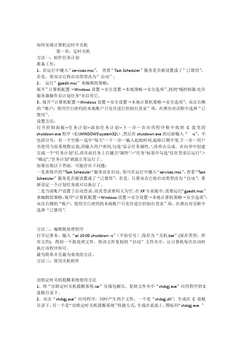
如何实现计算机定时开关机第一章:定时关机方法一:制作任务计划准备工作:1、在运行中键入”services.msc”,查看”Task Scheduler”服务是否被设置成了”已禁用”,若是,要双击它将启动类型改为”自动”;2、运行”gpedit.msc”来编辑组策略:展开”计算机配置→Windows设置→安全设置→本地策略→安全选项”,找到"域控制器:允许服务器操作员计划任务"并启用它。
3、展开“计算机配置→Windows设置→安全设置→本地计算机策略→安全选项”;双击右侧的“账户:使用空白密码的本地账户只允许进行控制台登录”项,在弹出对话框中选择“已禁用”。
设置方法:打开控制面板--任务计划--添加任务计划--下一步—在应用程序框中找到C盘里的shutdown.exe程序(C:\WINDOWS\system32\),然后在shutdown.exe的后面输入“-s”,不包括引号,有一个空格—选中"每天"—下一步—输入起始时间,起始日期不变,下一步—用户名使用当前系统默认值,再输入用户密码,勾选"显示任务属性..",再单击完成。
在向导中创建完成一个"任务计划"后,再在此任务上右键点"属性">"任务"标签中勾选"仅在登录后运行">"确定","任务计划"就能正常运行了。
如果出现以下界面,可能存在下问题:一是系统中的“Task Scheduler”服务没有启动,你可在运行中键入“services.msc”,查看“Task Scheduler”服务是否被设置成了“已禁用”,若是,只要双击它将启动类型改为“自动”,重新设定一个计划任务就可以执行了。
二是当前账户设置了自动登录,而其登录密码又为空。
在XP专业版中,需要运行“gpedit.msc”来编辑组策略:展开“计算机配置→Windows设置→安全设置→本地计算机策略→安全选项”;双击右侧的“账户:使用空白密码的本地账户只允许进行控制台登录”项,在弹出对话框中选择“已禁用”。
设置电脑定时开关机教程通用一篇设置电脑定时开关机教程 1步骤一:启动系统按DEL,进入BIOS,然后选中“POWER __ENT __S"(电源管理设置),回车进入.在电源窗口中找到"__ ON AC/POWERLOSS"项,按回车,然后通过方向键设置其值为"POWER ON". 步骤二:选中"RESUME ON RTC ALARM"并按回车,接着通过方向键设置其值为"ENABLE"。
此时“Automatic Power Up”选项会弹出一个菜单,里面有三项选择:“Disabled、Every Day和By Date”,意思是“禁止、每天和指定日期”。
对于你的要求来说,我推荐第三项,这时会跳出一个日期和时间设置。
步骤三:选中"RTC ALARM DATE"按回车,然后将其值设定为"__Y",表示每天都进行一样的操作,按照同样的方法,分别将"RTC ALARM HOURS""RTC ALARM MINUTE""RTM ALARM SECOND"设置为"09""20""00",这表示开机时间为早上的"9:20:00",全部设置好后,按F10,保存并重新启动.(由于不同的主板的BIOS不一样,有些主板的设置可能与上面的有一点点不同,但只要记住在电源管理中找到"WAKE UP"字样的就行了,因为这是设置定时开机的选项)DOS开机首先开机后按住Delete键,就是平常常用的删除按键,然后就会进入到BIOS界面。
虽然是一个满眼E文的蓝色世界,但不要害怕,没有问题的。
在BIOS设置主界面中选择“Power”选项,进入电源管理窗口。
如何设置电脑自动关机和定时开关电脑已成为现代人生活中不可或缺的工具之一,但有时候我们可能需要在一定的时间后或在特定的时间点将电脑自动关机,或者定时开启电脑以完成一些任务。
本文将介绍如何设置电脑的自动关机和定时开关,以满足你的需求。
一、Windows系统下的设置在Windows系统下,我们可以使用任务计划程序来实现电脑的自动关机和定时开关。
1. 自动关机要设置电脑自动关机,首先点击任务栏左侧的“开始”按钮,然后在搜索框中键入“任务计划程序”,并点击打开。
在任务计划程序窗口中,点击左侧的“创建基本任务”来创建一个新的任务。
接下来,按照提示进行设置。
你可以自定义任务的名称和描述,然后选择你希望任务在何时触发,例如每天固定的时间、电脑启动后、空闲一段时间后等。
再选择“启动程序”并设置关机命令(一般为shutdown -s),最后点击“完成”按钮即可。
2. 定时开关要设置电脑的定时开关,同样打开任务计划程序。
选择“创建基本任务”后,根据提示进行设置。
你可以自定义任务的名称和描述,然后选择你希望任务在何时触发,例如每天固定的时间、电脑启动后、特定事件发生后等。
再选择“启动程序”并设置开机(shutdown -s)或重启(shutdown -r)命令,最后点击“完成”按钮即可。
二、Mac系统下的设置在Mac系统下,我们可以使用“定时启动或关闭”功能来实现电脑的自动关机和定时开关。
1. 自动关机要设置电脑自动关机,首先点击屏幕左上角的苹果图标,然后选择“系统偏好设置”。
在系统偏好设置窗口中,点击“能源节能”选项。
在能源节能选项卡中,点击右下角的“计划…”按钮。
接下来,在计划窗口中勾选“睡眠”和“自动开启或关闭”,然后点击“设定时间…”按钮来设置关机的时间。
最后点击“应用”按钮即可完成设置。
2. 定时开关要设置电脑的定时开关,同样进入“能源节能”选项卡,在计划窗口中勾选“睡眠”和“自动开启或关闭”,然后点击“设定时间…”按钮来设置开关机的时间。
定时设置步骤如下:步骤按键设定项目1 按“定时”进入第1组定时开的设定(显示|开)2 按“星期、时、分”设定开启时间(星期、时、分)3 按“定时”进入第1组定时开关的设定(显示|关)4 按“星期、时、分”设定关的时间(星期、时、分)5 重复“1、2、3、4”步骤可设定2-10组开关的时间6 郑州鸿联TB1025定时开关重复按“定时”检查各组开关时间和星期是否与要求的一样,如果不正确,还应重复步骤2、47 郑州鸿联TB1025定时开关按“自动/手动”请根据当前时钟时间在设定的自控时间里处于开或关,确定开关符号从“开”调到“自动”或从“关”调到“自动”。
8 郑州鸿联TB1025定时开关按“时钟”结束时间设定进入时钟显示状态。
* TB1025定时开关注意:如不需要设定10组,把多余的组数用[取消/恢复]键取消,显示“--:-- ”即表示消除,若再按一次[取消/恢复]键可恢复消除前的原有时间设定。
*郑州鸿联TB1025定时开关检查:连续按[定时]键检查每一组所设定的时间、星期是否正确。
* 郑州鸿联TB1025定时开关修改:按[定时]键至需修改的定时组,按[取消/恢复]键消除当前设置,然后可按定时设置有关步骤重新设定该组开关时间(星期、时、分)。
*郑州鸿联TB1025定时开关手动控制:按[手动/自动]键可直接开、关电源,在“开”状态时,一直开;在“关”状态时,一直关;在“自动”状态时,自动执行已设定的时间程序。
* 郑州鸿联TB1025定时开关在非“时钟显示”状态下,按[时钟]键或30秒未按任何键,保存当前设置可恢复到时钟显示状态。
* 郑州鸿联TB1025定时开关如需日控循环,请务必将定时时间(开和关)均设置在星期全显状态。
郑州鸿联TB1025定时开关四、郑州鸿联TB1025定时开关注意事项* 郑州鸿联TB1025定时开关若显示屏显示变弱或不显示时,请先更换电池(电池在接线端子盖下面,拧下固定螺丝,掀开盖后既可方便的更换),更换电池后,若原设定内容消失、需重新设定。
定时设置
调校时钟:按住“时钟”,同时按“时、分、星期”键可调校时钟、星期。
定时设置步骤如下:
步骤按键设定项目
1 按“定时”进入第1组定时开的设定(显示|开)
2 按“星期、时、分”设定开启时间(星期、时、分)
3 按“定时”进入第1组定时开关的设定(显示|关)
4 按“星期、时、分”设定关的时间(星期、时、分)
5 重复“1、2、3、4”步骤可设定2-10组开关的时间
6 重复按“定时”检查各组开关时间和星期是否与要求的一样,如果不正确,还应重复步骤2、4
7 按“自动/手动”请根据当前时钟时间在设定的自控时间里处于开或关,确定开关符号从“开”调到“自动”或从“关”调到“自动”。
8 按“时钟”结束时间设定进入时钟显示状态。
* 注意:如不需要设定10组,把多余的组数用[取消/恢复]键取消,显示“--:--”即表示消除,若再按一次[取消/恢复]键可恢复消除前的原有时间设定。
* 检查:连续按[定时]键检查每一组所设定的时间、星期是否正确。
* 修改:按[定时]键至需修改的定时组,按[取消/恢复]键消除当前设置,然后可按定时设置有关步骤重新设定该组开关时间(星期、时、分)。
* 手动控制:按[手动/自动]键可直接开、关电源,在“开”状态时,一直开;在“关”状态时,一直关;在“自动”状态时,自动执行已设定的时间程序。
* 在非“时钟显示”状态下,按[时钟]键或30秒未按任何键,保存当前设置可恢复到时钟显示状态。
* 如需日控循环,请务必将定时时间(开和关)均设置在星期全显状态。
订金活动:付200元,抵400元货款
赠送套餐1:全场橱柜金额满10000元
加318元送价值3457元樱雪烟机一台
加198元送价值2054元樱雪灶具一台
加298元送价值2980元樱雪消毒柜一台
赠送套餐2:全场橱柜金额满15000元
加318元送价值3457元樱雪烟机一台
加198元送价值1980元樱雪灶具一台
加298元送价值3620元樱雪消毒柜一台
加10元送价值1280元304钢大小高级水盆套餐一套我五一也想到那去看看。