光催化分解水综述..共61页文档
- 格式:ppt
- 大小:4.97 MB
- 文档页数:31
光催化水分解产氢技术研究随着环境污染的不断加剧和气候变化的不可逆转,寻找可再生能源成为了全球共同关注的焦点。
氢气作为一种环保、高能效的能源,具有巨大的应用前景。
然而,目前主要的氢气生产方式仍然依赖于化石燃料,对环境造成了严重的污染。
因此,开发一种高效、环保的氢气生产技术变得尤为重要。
光催化水分解技术作为一种新兴的可持续能源制氢方法,备受科学家们的关注。
一、光催化水分解技术概述光催化水分解技术是一种利用光能将水分解成氢气和氧气的方法。
该技术的基本原理是利用光催化剂吸收太阳能的光线,通过催化作用解离水分子,产生氢气和氧气。
光催化水分解技术相较于传统的氢气生产方式更加环保,无二氧化碳排放,具有巨大的潜力。
二、光催化水分解机理光催化水分解的机理主要涉及到光吸收、光生电子、光生空穴和水分子的解离三个过程。
首先,光催化剂吸收光子,进而激发出电子和空穴。
接着,电子和空穴分别在催化剂表面进行迁移,与水分子接触。
最后,光生的电子和空穴参与水分子的解离反应,产生氢气和氧气。
三、提高光催化水分解效率的方法为了提高光催化水分解的效率,科学家们采取了多种方法。
首先,优化催化剂的结构和成分,以提高光吸收能力和电子传输效率。
其次,改善催化剂的表面特性,增加活性位点,提高催化活性。
此外,还可以通过控制反应条件,如温度、压力和pH值等,来优化反应过程。
四、光催化水分解技术的应用前景光催化水分解技术具有广阔的应用前景。
首先,该技术可以应用于氢气生产领域,为解决能源危机和环境问题提供可持续的能源解决方案。
其次,光催化水分解技术还可以应用于光催化反应和有机合成等领域,提高反应效率,减少环境污染。
综上所述,光催化水分解技术作为一种新兴的可持续能源制氢方法,具有巨大的潜力和应用前景。
在未来的研究中,科学家们将继续努力改进催化剂设计和反应条件控制,以提高光催化水分解效率,促进其商业化应用。
相信在不久的将来,光催化水分解技术将在能源领域发挥重要作用,为构建可持续发展的社会做出贡献。
光电催化水分解的研究与应用
光电催化水分解是一种将太阳能转化为可用能源的新技术,其研究和应用已经
引起了广泛关注。
在这篇文章中,我们将会探讨光电催化水分解的原理、研究进展和应用前景。
一、原理
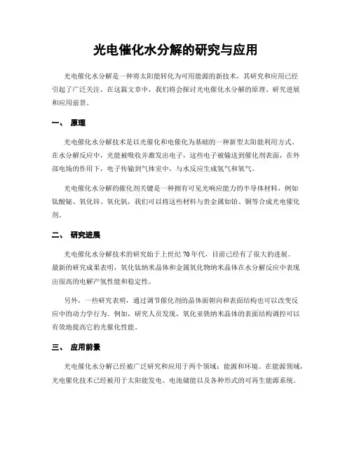
光电催化水分解技术是以光催化和电催化为基础的一种新型太阳能利用方式。
在水分解反应中,光能被吸收并激发出电子,这些电子被输送到催化剂表面,在外部电场的作用下,电子传输到气体室中,与水反应生成氢气和氧气。
光电催化水分解的催化剂关键是一种拥有可见光响应能力的半导体材料,例如
钛酸铋、氧化锌、氧化钒,我们可以将这些材料与贵金属如铂、铜等合成光电催化剂。
二、研究进展
光电催化水分解技术的研究始于上世纪70年代,目前已经有了很大的进展。
最新的研究成果表明,氧化钛纳米晶体和金属氧化物纳米晶体在水分解反应中表现出很高的电解产氢性能和稳定性。
另外,一些研究表明,通过调节催化剂的晶体面朝向和表面结构也可以改变反
应中的动力学行为。
例如,研究人员发现,氧化亚铁纳米晶体的表面结构调控可以有效地提高它的光催化性能。
三、应用前景
光电催化水分解已经被广泛研究和应用于两个领域:能源和环境。
在能源领域,光电催化技术已经被用于太阳能发电、电池储能以及各种形式的可再生能源系统。
在环境领域,光电催化水分解技术可以通过分解污染物来清除水污染。
同时还可以生产纳米材料、制备电极和刻写电子器件等各种应用。
总之,光电催化水分解技术是一种相对较新的技术,在科研和产业界都有广泛应用前景。
随着人们对低碳、绿色能源的需求增加,相信光电催化水分解技术将会在未来发挥越来越大的作用。


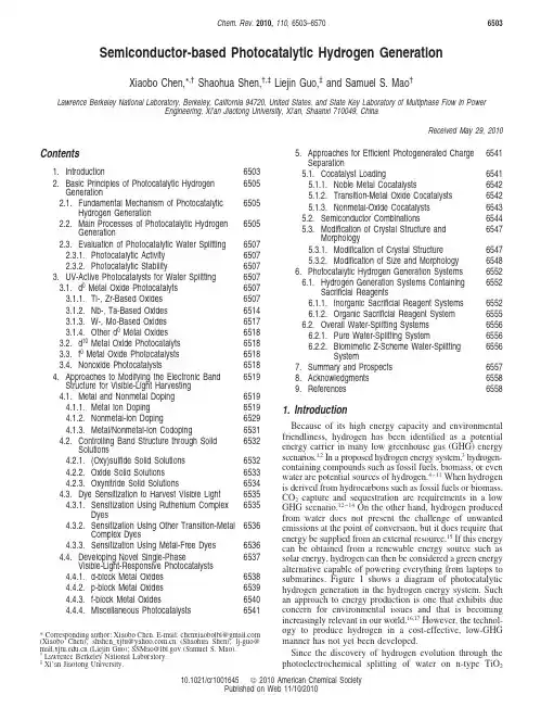
Semiconductor-based Photocatalytic Hydrogen GenerationXiaobo Chen,*,†Shaohua Shen,†,‡Liejin Guo,‡and Samuel S.Mao†Lawrence Berkeley National Laboratory,Berkeley,California94720,United States,and State Key Laboratory of Multiphase Flow in PowerEngineering,Xi’an Jiaotong University,Xi’an,Shaanxi710049,ChinaReceived May29,2010Contents1.Introduction65032.Basic Principles of Photocatalytic HydrogenGeneration65052.1.Fundamental Mechanism of PhotocatalyticHydrogen Generation65052.2.Main Processes of Photocatalytic HydrogenGeneration65052.3.Evaluation of Photocatalytic Water Splitting65072.3.1.Photocatalytic Activity65072.3.2.Photocatalytic Stability65073.UV-Active Photocatalysts for Water Splitting65073.1.d0Metal Oxide Photocatalyts65073.1.1.Ti-,Zr-Based Oxides65073.1.2.Nb-,Ta-Based Oxides65143.1.3.W-,Mo-Based Oxides65173.1.4.Other d0Metal Oxides65183.2.d10Metal Oxide Photocatalyts65183.3.f0Metal Oxide Photocatalysts65183.4.Nonoxide Photocatalysts65184.Approaches to Modifying the Electronic BandStructure for Visible-Light Harvesting65194.1.Metal and Nonmetal Doping65194.1.1.Metal Ion Doping65194.1.2.Nonmetal-Ion Doping65294.1.3.Metal/Nonmetal-Ion Codoping65314.2.Controlling Band Structure through SolidSolutions65324.2.1.(Oxy)sulfide Solid Solutions65324.2.2.Oxide Solid Solutions65334.2.3.Oxynitride Solid Solutions65344.3.Dye Sensitization to Harvest Visible Light65354.3.1.Sensitization Using Ruthenium ComplexDyes65354.3.2.Sensitization Using Other Transition-MetalComplex Dyes65364.3.3.Sensitization Using Metal-Free Dyes65364.4.Developing Novel Single-PhaseVisible-Light-Responsive Photocatalysts65374.4.1.d-block Metal Oxides65384.4.2.p-block Metal Oxides65394.4.3.f-block Metal Oxides65404.4.4.Miscellaneous Photocatalysts65415.Approaches for Efficient Photogenerated ChargeSeparation65415.1.Cocatalyst Loading65415.1.1.Noble Metal Cocatalysts65425.1.2.Transition-Metal Oxide Cocatalysts65425.1.3.Nonmetal-Oxide Cocatalysts65435.2.Semiconductor Combinations65445.3.Modification of Crystal Structure andMorphology65475.3.1.Modification of Crystal Structure65475.3.2.Modification of Size and Morphology65486.Photocatalytic Hydrogen Generation Systems65526.1.Hydrogen Generation Systems ContainingSacrificial Reagents65526.1.1.Inorganic Sacrificial Reagent Systems6552anic Sacrificial Reagent System65556.2.Overall Water-Splitting Systems65566.2.1.Pure Water-Splitting System65566.2.2.Biomimetic Z-Scheme Water-SplittingSystem65567.Summary and Prospects65578.Acknowledgments65589.References6558 1.IntroductionBecause of its high energy capacity and environmental friendliness,hydrogen has been identified as a potential energy carrier in many low greenhouse gas(GHG)energy scenarios.1,2In a proposed hydrogen energy system,3hydrogen-containing compounds such as fossil fuels,biomass,or even water are potential sources of hydrogen.4-11When hydrogen is derived from hydrocarbons such as fossil fuels or biomass, CO2capture and sequestration are requirements in a low GHG scenario.12-14On the other hand,hydrogen produced from water does not present the challenge of unwanted emissions at the point of conversion,but it does require that energy be supplied from an external resource.15If this energy can be obtained from a renewable energy source such as solar energy,hydrogen can then be considered a green energy alternative capable of powering everything from laptops to submarines.Figure1shows a diagram of photocatalytic hydrogen generation in the hydrogen energy system.Such an approach to energy production is one that exhibits due concern for environmental issues and that is becoming increasingly relevant in our world.16,17However,the technol-ogy to produce hydrogen in a cost-effective,low-GHG manner has not yet been developed.Since the discovery of hydrogen evolution through the photoelectrochemical splitting of water on n-type TiO2*Corresponding author:Xiaobo Chen.E-mail:chenxiaobolbl@(Xiaobo Chen);shshen_xjtu@(Shaohua Shen);lj-guo@(Liejin Guo);SSMao@(Samuel S.Mao).†Lawrence Berkeley National Laboratory.‡Xi’an Jiaotong University.Chem.Rev.2010,110,6503–6570650310.1021/cr1001645 2010American Chemical SocietyPublished on Web11/10/2010electrodes,18the technology of semiconductor-based photo-catalytic water splitting to produce hydrogen using solar energy has been considered as one of the most important approaches to solving the world energy crisis.19Hence,the development of the necessary semiconductor photocatalysts has undergone considerable research.Over the past40years, many photocatalysts reportedly exhibited high photocatalytic activities for splitting water into a stoichiometric mixture of H2and O2(2:1by molar ratio)in the ultraviolet(UV)light region.These include La doped NaTaO3,20Sr2M2O7(M) Nb,Ta),21La2Ti2O7,22K2La2Ti3O10,23and -Ge3N4,24among others.Of particular note is the NiO/NaTaO3:La photocata-lyst,which shows the highest activity with a quantum yield amounting to56%at270nm.20However,these oxide photocatalysts are only active under UV irradiation.With respect to the solar spectrum,only a small fraction(ca.4%) of the incoming solar energy lies in the ultraviolet region, whereas the visible light in the solar spectrum is far more abundant(ca.46%).It is essential,therefore,as an alternative to UV-active photocatalysts to develop visible-light-driven photocatalysts that are stable and highly efficient for the practical,large-scale production of hydrogen using solar energy.Over the recent years,continuing breakthroughs have been made in the development of novel visible-light-driven photocatalysts,leading to the enhancement of photocatalytic activity for water splitting and inspiring great enthusiasm.A large number of semiconductor materials have been developed as photocatalysts for water splitting to hydrogen under visible-light irradiation.A significant process has been achieved on semiconductor-based photocatalytic hydrogen generation through waterDr.Xiaobo Chen is at Lawrence Berkeley National Laboratory.He obtained his Ph.D.Degree in Chemistry from Case Western Reserve University. His research interests include materials and devices development, renewable energy science and technology,environmental pollution,and health.Dr.Shaohua Shen is an assistant professor at Xi’an Jiaotong University, China.He obtained his Ph.D.Degree in Thermal Engineering from Xi’an Jiaotong University in2010.During2008-2009,he worked as a guest researcher at Lawrence Berkeley National Laboratory,U.S.A.His research interests include photocatalysis,photoelectrochemistry,and the related materials and devices development.Dr.Liejin Guo is a professor and the director of the State Key Laboratory of Multiphase Flow in Power Engineering in Xi’an Jiaotong University, China.He obtained his Ph.D.Degree in Engineering Thermophysics from Xi’an Jiaotong University in1989.His research interest includes multiphase flow,heat transfer,and renewable energy technologies.Dr.Samuel S.Mao is a career staff scientist at Lawrence Berkeley National Laboratory and an adjunct faculty at The University of California at Berkeley.He obtained his Ph.D.degree in Engineering from The University of California at Berkeley in2000.He is leading a multidisciplinary research team developing solar-active materials and devices and investigating fundamental energy conversion processes.Figure1.Schematic diagram of photocatalytic hydrogen genera-tion in the hydrogen energy system.6504Chemical Reviews,2010,Vol.110,No.11Chen etal.splitting over the past several decades,25-31and many excellent reviews have been published.32-62In this review, we aim to put together the research effort having been made so far,with a view of providing a good reference and inspiring new ideas for tackling this important challenge. Starting with a brief introduction to semiconductor-based photocatalysts for hydrogen generation from water splitting, we overview the development of high-efficiency,visible-light-driven photocatalysts.A number of synthetic and modification techniques for adjusting the band structure to harvest visible light and improve the charge separation in photocatalysis are discussed.Photocatalytic systems for water splitting are also reviewed and classified into two main kinds: sacrificial reagent-containing water-splitting systems and overall water-splitting systems.2.Basic Principles of Photocatalytic Hydrogen Generation2.1.Fundamental Mechanism of Photocatalytic Hydrogen GenerationIn Fujishima and Honda’s pioneering work,the electro-chemical cell they constructed for the decomposition of water into hydrogen and oxygen is shown in Figure2.18When the surface of the TiO2electrode was irradiated by UV light,as a result of a water oxidation reaction,oxygen evolution occurred at the TiO2electrode.Concomitant reduction led to hydrogen evolution at the platinum black electrode.This concept,which emerged from the use of photoelectrochemi-cal cells with semiconductor electrodes,was later applied by Bard to the design of a photocatalytic system using semiconductor particles or powders as photocatalysts.63-65 A photocatalyst absorbs UV and/or visible(Vis)light irradiation from sunlight or an illuminated light source.The electrons in the valence band of the photocatalyst are excited to the conduction band,while the holes are left in the valence band.This,therefore,creates the negative-electron(e-)and positive-hole(h+)pairs.This stage is referred to the semiconductor’s“photo-excited”state,and the energy dif-ference between the valence band and the conduction band is known as the“band gap”.This must correspond to the wavelength of the light for it to be effectively absorbed by the photocatalyst.After photoexcitation,the excited electrons and holes separate and migrate to the surface of photocatalyst. Here,in the photocatalytic water-splitting reaction,they act as reducing agent and oxidizing agent to produce H2and O2,respectively.A schematic representation of the principle of the photocatalytic system for water is depicted in Figure 3.Water splitting into H2and O2is an uphill reaction.It needs the standard Gibbs free energy change∆G0of237kJ/mol or1.23eV,as shown in eq1.Therefore,the band gap energy(E g)of the photocatalyst should be>1.23eV(<1000nm)to achieve water splitting. However,to use visible light,it should be<3.0eV(>400 nm).To facilitate both the reduction and oxidation of H2O by photoexcited electrons and holes,the match of the band gap and the potentials of the conduction and valence bands are important.Both the reduction and oxidation potentials of water should lie within the band gap of the photocatalyst. The bottom level of the conduction band has to be more negative than the reduction potential of H+/H2(0V vs normal hydrogen electrode(NHE)),whereas the top level of the valence band has to be more positive than the oxidation potential of O2/H2O(1.23V).Parts A and B of Figure4 show the conduction band edge and valence band edge of some oxide-and sulfide-based semiconductor materials.66We can see that there are many semiconductor systems whose electronic structures match well with the redox potential of water into hydrogen and oxygen molecules.The band structure requirement is a thermodynamic requirement for water splitting.Other factors,such as overpotentials,charge separation,mobility,and lifetime of photogenerated electrons and holes,affect the photocatalytic generation of hydrogen from water splitting as well.For example,the band edges of the semiconductor photocatalyst usually vary with the change of pH,as shown in Figure4C.66The phase stability of the semiconductor photocatalyst changes in different pH environments as well.2.2.Main Processes of Photocatalytic Hydrogen GenerationThe processes in the photocatalytic generation of hydrogen are illustrated in Figure5.They include light absorption of the semiconductor photocatalyst,generation of excited charges(electrons and holes),recombination of the ex-cited charges,separation of excited charges,migration of the charges,trap of excited charges,and transfer of excitedFigure2.Schematic representation of a photoelectrochemical cell (PEC).Reprinted with permission from ref18.Copyright1972 Nature Publishing Group.Figure3.Fundamental principle of semiconductor-based photo-catalytic water splitting for hydrogen generation.H2O f12O2+H2;∆G)+237kJ/mol(1)Photocatalytic Hydrogen Generation Chemical Reviews,2010,Vol.110,No.116505charges to water or other molecules.All of these proces-ses affect the final generation of hydrogen from the semi-conductor photocatalyst system.The total amount of hydrogen generated is mainly determined by the amount of excited electrons in the water/photocatalyst interface in reducing water.Apparently,any other processes that consume excited electrons should be avoided in order to maximize the efficiency of the hydrogen generation of the photocatalyst system.Any process that generates excited electrons should be considered to act in a possible way to improve the efficiency.Thus,if we look atthe charge-generation process,the semiconductor photocata-lyst should first have a low band gap to absorb as much light as possible,and reflection or scattering of light by the photocatalyst should be minimized.Second,using the absorbed photons,the semiconductor photocatalyst should have a high efficieny in generating excited charges,instead of generating phonons or heat.After excited charges are created,charge recombination and separation/migration processes are two important com-petitive processes inside the semiconductor photocatalyst that largely affect the efficiency of the photocatalytic reaction for water splitting.67Charge recombination reduces the excited charges by emitting light or generating phonons.It includes both surface and bulk recombination and is classified as a deactivation process,and it is ineffective for water splitting.The separation of excited electrons and holes sometimes may need to overcome an energy barrier,which is the sometimes binding energy of the excited electron -hole pairs,excitons.Charge separation and migration,on the other hand,is an activation process.This is as a result of the charges being on the surface of the photocatalyst ready for the desired chemical reaction.It is beneficial for hydrogen generation through water splitting.Efficient charge separation and fast charge transport,avoiding any bulk/surface charge recombination avoided,are fundamentally important for photocatalytic hydrogen generation through water splitting.Any approach beneficial to the charge separation and transport should be taken into account such as design of internal-built electric field and use of high photoconductive semiconductor materials.The reaction of photogenerated H 2and O 2to form H 2O on the photocatalyst surface is normally called “surface back-reaction (SBR)”.It will inevitably have a negative effect on any enhancement of the photocatalytic activity,because it reduces the amount of H 2emitted from the photocatalyst.There are two main approaches to suppress SBR:one involves the addition of sacrificial reagents into the photo-catalytic reaction environment and the second creates a separation of the photoactive sites on the surface of the photocatalysts.In general,the electron donor and acceptor sacrificial reagents that are added work as an external driving force for the surface chemical reaction and depress the H 2O formation from H 2and O 2.The separation of the photoactive sites necessary for hydrogen and oxygen evolution,andFigure4.Calculated energy positions of conduction band edges and valence band edges at pH 0for selected metal oxide (A)and metal sulfide (B)semiconductors.The bottom of open squares represent conduction band edges,and the top of solid squares represent valence band edges.The solid lines indicate water stability limits.(C)pH dependence of the conduction band edge and valence band edge in an aqueous electrolyte solution.Reprinted with permission from ref 66.Copyright 2000The Mineralogical Society of America.Figure 5.Processes in photocatalytic water splitting.Reprinted with permission from ref 67.Copyright 1995American Chemical Society.6506Chemical Reviews,2010,Vol.110,No.11Chen et al.which is always accompanied by the surface separation ofthe photogenerated electrons and holes,has been shown tobe greatly affected by the surface properties of the photo-catalysts.As well as the surface reaction sites themselves,the surface states and morphology also play an importantrole.Taking into consideration the basic mechanism andprocesses of photocatalytic water splitting,there are two keysto developing a suitable high-efficiency semiconductor forthe visible-light-driven photocatalytic splitting of water intoH2and/or O2:(1)A photocatalyst should have a sufficientlynarrow band gap(1.23eV<E g<3.0eV)to both harvest visible light and possess the correct band structure.(2)Photoinduced charges in the photocatalyst should be sepa-rated efficiently in order to avoid bulk/surface electron/holerecombination.In addition,they must migrate to the pho-tocatalyst surface for hydrogen and/or oxygen evolution at the respective photocatalytic active sites.58In summary,it is generally accepted that the correct band structure for efficient visible-light harvesting and effective separation between the photoexcited electrons and the holes is essential to improve the photocatalytic properties of the semiconduc-tor.In addition,with the development of efficient visible-light-driven photocatalysts,it is important that economical, highly efficient photocatalytic systems for light-to-hydrogen energy conversion,in which aqueous solutions containing sacrificial reagents can be used to depress the backward reaction of hydrogen and oxygen to water on the surface of photocatalysts,can be constructed.2.3.Evaluation of Photocatalytic Water Splitting There are two apparent indicators that should be paid attention in evaluating the hydrogen generation through photocatalytic water splitting.One is photocatalytic activity, and the other one is photocatalytic stability.2.3.1.Photocatalytic ActivityThe efficiency of photocatalytic hydrogen generation from water splitting can be measured directly on the amount of hydrogen gas evoluted or indirectly on the electrons trans-ferred from semiconductor to water within a certain time period under light irradiation.Different photocatalytic setup configurations,such as inner irradiation type and top irradia-tion type,and light sources,such as Xe lamp and Hg lamp, are commonly used by different research groups and scientists,which may give different rates of gas evolution when exactly the same photocatalyst is used.This makes it difficult to make direct comparison across the results from different research groups and photocatalytic hydrogen gen-eration systems.Nevertherless,it seems helpful to get approximate correlations between various results if we normalize the rates of gas evolution to the amount of photocatalyst employed within a unit of time.Here,we use the rate of gas(O2and H2)evolution with units such as µmol·h-1andµmol·h-1·g-1catalyst to make the mensurable comparison between different photocatalysts under similar experimental conditions.The(apparent)quantum yield,as an extension from the overall quantum yield in a homogeneous photochemical system,becomes important and acceptable to evaluate the photocatalytic activity for water splitting.The overall quantum yield and apparent quantum yield are defined by eqs2and3,respectively.68The apparent quantum yield is estimated to be smaller than the total quantum yield because the number of absorbed photons is usually smaller than that of incident light.In addition to the quantum yield,the solar energy conversion efficiency that is usually used for evaluation of solar cells is also sometimes reported in the literature.It is defined as 2.3.2.Photocatalytic StabilityAs a good photocatalyst,it should have a good stability for H2and/or O2production,besides a high photocatalytic activity or quantum yield.To test the photocatalytic stability, a long-time experiment or a repeated experiment is always necessary.Photocorrosion is considered to be the main reason causing the poor stability of photocatalysts,especially the metal sulfide photocatalysts.CdS has frequently been reported to be unstable for photocatalytic H2evolution.S2-in CdS rather than water is self-oxidized by photoinduced holes in the valence band of CdS.The photocorrosion reaction occurs as in eq5,553.UV-Active Photocatalysts for Water SplittingA wide range of semiconducting materials have been developed as photocatalysts for use under UV irradiation. These are shown in Table1.On the basis of their electronic configuration properties,these UV-active photocatalysts can be typically classified into four groups:(1)d0metal(Ti4+, Zr4+,Nb5+,Ta5+,W6+,and Mo6+)oxide photocatalysts,(2) d10metal(In3+,Ga3+,Ge4+,Sn4+,and Sb5+)oxide photo-catalysts,(3)f0metal(Ce4+)oxide photocatalysts,and(4)a small group of nonoxide photocatalysts.3.1.d0Metal Oxide Photocatalyts3.1.1.Ti-,Zr-Based OxidesTiO2is thefirst reported photocatalyst for water splitting under UV irradiation.69TiO2can produce hydrogen and/or oxygen from water vapor,pure water,and aqueous solutions containing electron donor.70-77It was found that,under UV irradiation,colloidal TiO2combined with ultrafine Pt and RuO2particles generated H2with a high quantum yield of 30(10%and O2in stoichiometric proportions from water.70 The reaction solution had a pH of1.5,which was adjusted Overall quantum yield(%))Number of reacted electronsNumber of absorbed photons×100%(2)(Apparent)Quantum yield(QY,%))Number of reacted electronsNumber of incident photons×100%)2×Number of evolved H2moleculesNumber of incident photons×100%(for H2evolution))4×Number of evolved O2moleculesNumber of incident photons×100%(for O2evolution)(3)Solar energy conversion(%))Output energy of hydrogen evolvedEnergy of incident solar light×100(4)CdS+2h+f Cd2++S(5)Photocatalytic Hydrogen Generation Chemical Reviews,2010,Vol.110,No.116507T a b l e 1.U V -L i g h t -A c t i v e P h o t o c a t a l y s t s f o r W a t e r S p l i t t i n g t o H y d r o g e n a n d /o r O x y g e n a c t i v i t y (µm o l ·h -1·g -1)p h o t o c a t a l y s t s y n t h e t i c m e t h o dm a s s (g )l i g h t s o u r c e i n c i d e n t l i g h t a q u e o u s r e a c t i o n s o l u t i o n c o -c a t a l ./H 2c o -c a t a l ./O 2Q Y (%)r e f e r e n c eT i O 2(a n a t a s e )M C B T i O 20.3500-W H g b250-400n m w a t e r v a p o r R h /149729(340n m )74T i O 2(a n a t a s e )M C B T i O 21450-W H g q u a r t z fil t e r N a O H N i O x /32N i O x /1475T i O 2(a n a t a s e ,78%)P 25T i O 20.3400-W H g q u a r t z fil t e r N a 2C O 3P t /1893P t /95771T i O 2(a n a t a s e ,78%)P 25T i O 20.3250-W H g P y r e x fil t e r p u r e w a t e r P t /353P t /1771.4(300-400n m )76T i O 2h y d r o l y s i s ,c a l c i n a t i o n 0.2300-W X e cP y r e x fil t e r C H 3O H P t /∼330072r u t i l e /a n a t a s e T i O 2i m p r e g n a t i o n ,c a l c i n a t i o n 0.2300-W X e P y r e x fil t e r C H 3O H P t /∼670073c o l l o i d T i O 2h y d r o l y s i s r e a c t i o n 0.025450-W H g P y r e x fil t e r H C l P t -R u O 2/400030(310n m )70m e s o p o r o u s T i O 2s o l g e l m e t h o d 0.2300-W H g P y r e x fil t e r C H 3O H P t /6925889,934,941T i O 2n a n o w i r e s e l e c t r o s p i n n i n g a n d s o l -g e l 1450-W H g P y r e x fil t e r C H 3O H 54964,975T i O 2n a n o t u b e s h y d r o t h e r m a l m e t h o d 1450-W H g P y r e x fil t e r C H 3O H 285966T i O 2n a n o s h e e t s h y d r o t h e r m a l m e t h o d 1450-W H g P y r e x fil t e rC H 3O H 117.61003N i -i n t e r c a l a t e d N a 2T i 2O 5n a n o t u b e s h y d r o t h e r m a l m e t h o d 0.1450-W H g C H 3O H P t /∼85099T i O 2:G a s o l v o t h e r m a l m e t h o d 1.5U V -l a m p s P y r e x fil t e r P u r e w a t e r 20.8679T i O 2:N i h y d r o t h e r m a l m e t h o d 0.3300-W H g P y r e x fil t e r C H 3O H P t /∼566.780T i O 2:S c h y d r o l y s i s ,c a l c i n a t i o n 0.1300-W H g P y r e x fil t e r C H 3O H P t /∼750082T i O 2:Y h y d r o l y s i s ,c a l c i n a t i o n 0.1300-W H g P y r e x fil t e r C H 3O H P t /∼780082T i O 2:L a h y d r o l y s i s ,c a l c i n a t i o n 0.1300-W H g P y r e x fil t e r C H 3O H P t /∼768082T i O 2:C e h y d r o l y s i s ,c a l c i n a t i o n 0.1300-W H g P y r e x fil t e r C H 3O H P t /∼480082T i O 2:P r h y d r o l y s i s ,c a l c i n a t i o n 0.1300-W H g P y r e x fil t e r C H 3O H P t /∼660082T i O 2:N d h y d r o l y s i s ,c a l c i n a t i o n 0.1300-W H g P y r e x fil t e r C H 3O H P t /∼930082T i O 2:S m h y d r o l y s i s ,c a l c i n a t i o n 0.1300-W H g P y r e x fil t e r C H 3O H P t /∼1020082T i O 2:G d h y d r o l y s i s ,c a l c i n a t i o n 0.1300-W H g P y r e x fil t e r C H 3O H P t /∼1080082T i O 2:E u h y d r o l y s i s ,c a l c i n a t i o n 0.1300-W H g P y r e x fil t e r C H 3O H P t /∼1320082T i O 2:T b h y d r o l y s i s ,c a l c i n a t i o n 0.1300-W H g P y r e x fil t e r C H 3O H P t /∼480082T i O 2:D y h y d r o l y s i s ,c a l c i n a t i o n 0.1300-W H g P y r e x fil t e r C H 3O H P t /∼840082T i O 2:H o h y d r o l y s i s ,c a l c i n a t i o n 0.1300-W H g P y r e x fil t e r C H 3O H P t /∼1020082T i O 2:E r h y d r o l y s i s ,c a l c i n a t i o n 0.1300-W H g P y r e x fil t e r C H 3O H P t /∼840082T i O 2:T m h y d r o l y s i s ,c a l c i n a t i o n 0.1300-W H g P y r e x fil t e r C H 3O H P t /∼870082T i O 2:Y b h y d r o l y s i s ,c a l c i n a t i o n 0.1300-W H g P y r e x fil t e r C H 3O H P t /∼840082T i O 2:L u h y d r o l y s i s ,c a l c i n a t i o n 0.1300-W H g P y r e x fil t e r C H 3O H P t /∼720082T i O 2:S n /E u p o l y o l m e t h o d 0.2288-WF dq u a r t z fil t e r C H 3O H P d /∼9240.481T i O 2/C u x O i m p r e g n a t i o n m e t h o d 1400-W H g q u a r t z fil t e r C H 3O H 1850085-87T i O 2/S n O 2p o l y o l m e t h o d 0.05288-W F q u a r t z fil t e r C H 3O H P d /∼8383A g x O /T i O 2i m p r e g n a t i o n m e t h o d 0.05s o l a r l i g h t q u a r t z fil t e rC H 3O H 6700088-90S r T i O 3/T i O 2s o l i d -s t a t e r e a c t i o n 0.1150-W H g H C O O H 56091B /T i o x i d e s o l -g e l m e t h o d 0.3400-W H g q u a r t z fil t e r p u r e w a t e r P t /73P t /36.792,93m e s o -T i O 2/Z r O 2e v a p o r a t i o n i n d u c e d s e lf -a s s e m b l y p r o c e s s 0.06500-W Hg P y r e x fil t e r C H 3O H P t /∼2484C a T i O 3S a k a i C h e m i c a l I n d u s t r y 0.5500-W H g s i l i c a g l a s s N a O H P t /76P t /18120S r T i O 3A l f a -V e n t r o n 0.5400-W H g P y r e x fil t e r N a O H N i O x /∼70N i O x /∼32109-114S r T i O 3:L a s o l i d -s t a t e r e a c t i o n 0.1400-W H g q u a r t z fil t e r N a 2C O 3C o O x /∼2800C o O x /∼1300116S r T i O 3:T a s o l i d -s t a t e r e a c t i o n 0.3450-W H g P y r e x fil t e r p u r e w a t e r R h x C r 2-x O 3/∼14160R h x C r 2-x O 3/∼7000117S r T i O 3:N a s o l i d -s t a t e r e a c t i o n 0.3450-W H g P y r e x fil t e r p u r e w a t e r R h x C r 2-x O 3/∼22220R h x C r 2-x O 3/∼11110117S r 3T i 2O 7p o l y m e r i z e d c o m p l e x m e t h o d 1400-W H g q u a r t z fil t e r p u r e w a t e r N i O x /144N i O x /72118S r 4T i 3O 10p o l y m e r i z e d c o m p l e x m e t h o d 1400-W H g q u a r t z fil t e r p u r e w a t e r N i O x /1704.5(360n m )119K 2L a 2T i 3O 10p o l y m e r i z e d c o m p l e x m e t h o d 1450-W H g q u a r t z fil t e r K O H N i O x /2186N i O x /113123,135,139R b 2L a 2T i 3O 10s o l i d -s t a t e r e a c t i o n 1450-W H g q u a r t z fil t e r R b O H N i O x /869N i O x /4305(330n m )135R b 1.5L a 2T i 2.5N b 0.5O 10s o l i d -s t a t e r e a c t i o n 1450-W H g q u a r t z fil t e r R b O H N i O x /725N i O x /358135R b L a 2T i 2N b O 10s o l i d -s t a t e r e a c t i o n 1450-W H g q u a r t z fil t e r R b O H N i O x /79N i O x /30135C s 2L a 2T i 3O 10s o l i d -s t a t e r e a c t i o n 1450-W H g q u a r t z fil t e r p u r e w a t e r N i O x /700N i O x /340135C s 1.5L a 2T i 2.5N b 0.5O 10s o l i d -s t a t e r e a c t i o n 1450-W H g q u a r t z fil t e r p u r e w a t e r N i O x /540N i O x /265135C s L a 2T i 2N b O 10s o l i d -s t a t e r e a c t i o n 1450-W H g q u a r t z fil t e r p u r e w a t e r N i O x /115N i O x /50135L a T i O 3s o l i d -s t a t e r e a c t i o n 1450-W H g q u a r t z fil t e r p u r e w a t e r N i O x /137125L a 2T i O 5s o l i d -s t a t e r e a c t i o n 1450-W H g q u a r t z fil t e r p u r e w a t e r N i O x /442125L a 2T i 3O 9s o l i d -s t a t e r e a c t i o n 1450-W H g q u a r t z fil t e r p u r e w a t e r N i O x /386125L a 4T i 3O 12p o l y m e r i z e d c o m p l e x m e t h o d 0.5400-W H g q u a r t z fil t e r p u r e w a t e r N i O /714N i O /358133L a 2T i 2O 7p o l y m e r i z e d c o m p l e x m e t h o d 1450-W H g q u a r t z fil t e r p u r e w a t e r N i O x /960N i O x /4782722,122-127,131,134L a 2T i 2O 7:S r s o l i d -s t a t e r e a c t i o n 1450-W H g q u a r t z fil t e rp u r e w a t e r N i O x /15101256508Chemical Reviews,2010,Vol.110,No.11Chen et al.。

催化分解水的基本原理。
锐钛矿型的Ti02其价带到导带的禁带宽度约为3.2eV,当受到光子能量等于或高于禁带宽度的光辐照时,其价带上的电子(e一)就会受激跃迁至导带,在价带上产生相应的空穴(h+),形成了电子一空穴对。
产生的电子、空穴在内部电场作用下分离并迁移到粒子表面。
光生空穴有很强的得电子能力,具有强氧化性,可夺取半导体颗粒表面被吸附物质或溶剂中的电子,使原本不吸收光的物质被氧化,电子受体则通过接受表面的电子而被还原,完成光催化反应过程,如图1所示[¨:图1光催化分解水的基本过程模型①半导体光催化剂吸收能量足够大的光子,产生电子一空穴对;⑦电子一空穴对分离,向半导体光催化剂表面移动;③电子与水反应产生氢气I④空穴与水反应产生氧气I⑤部分电子与空穴复合,产生热或光。
光催化分解水反应式可写为(以Ti02为例)‘“l2Ti02+2hv—・2Ti02+2h++2e一(1)2e一+2H+—・H’+H‘一H2(Z)2h++2H20一2H。
o+一20H’+2H+(3)oH‘+oH‘—,H:o+1/202(4)但也并不是所有的半导体光催化剂都能作为光分解水的催化剂,必须满足一定的氧化还原化学反应条件,即首先其禁带宽度要大于水的分解电压(理论值1.23eV),且由于超电压的存在,半导体材料的禁带宽度要大于水的分解电压,其次,半导体光催化剂的价带位置应比O。
/H。
o的电位更正,而导带的位置应比H+/H。
更负,最合适的禁带宽度应为2.0eV左右‘…。
3光催化分解水体系自从Fujishima和Honda发现可以利用二氧・128・化钛(Ti02)光催化分解水制备氢气和氧气以来,各国学者一直致力于光催化分解水的研究,并在高效光催化剂的研究方面取得了重要进展,开发了为数众多的光催化剂o]。
目前,光催化分解水的评价体系主要是粉末直接光照的水溶早匝悬浮反应体系和光电化学体系。
其中,粉末悬浮作为光催化分解水制氢的反应体系可用来评价半导体光催化剂的许多性质,如导带与价带的位置、禁带宽度、材料本身在水溶液中的稳定性等。
cof光催化全分解水
COF光催化全分解水是一种利用共轭有机框架材料(COF)
作为光催化剂,在光照条件下将水分解为氧气和氢气的过程。
光催化全分解水的过程是通过吸收光能,激发电子从COF中
跃迁到导带带底部,形成电子空穴对。
电子和空穴对的形成促使水分子发生光解反应,将水分解为氧气和氢气。
COF作为光催化剂具有很多优势。
首先,COF具有高特异表
面积和可控的孔结构,有利于提供更多活性位点,并增加光吸收量。
其次,COF材料通常具有良好的光稳定性和光学性能,能够有效地利用太阳光进行光催化反应。
此外,COF材料具
有可调节的化学组成和结构,可以通过合成方法的调控来改变催化性能。
虽然COF光催化全分解水技术在实验研究中取得了一定的进展,但目前仍面临一些挑战。
首先,COF材料的合成和制备
方法需要进一步优化,以提高光催化性能和稳定性。
其次,COF材料的光吸收范围还需要拓宽,使其能够吸收更多的可
见光谱范围。
此外,还需要解决光催化过程中产生的副产物问题,以提高水分解的效率和选择性。
总体来说,COF光催化全分解水是一种具有潜力的技术,可
以为可持续能源的应用提供新的途径。
然而,还需要进一步的研究和开发,以克服现有的挑战并实现实际应用。

光催化研究发展综述性报告本人申请攻读动力工程与工程热物理专业博士学位,由于对后续能源与新能源技术专业太阳能分解水制氢方向有浓厚的兴趣,通过对相关文献的阅读和参加相关报告,对太阳能光催化分解水制氢有了详细的了解,对其发展简述如下:/ 、八1.前言当今人类社会面临能源和环境两大问题[1-2]。
能源的短缺和环境的污染严重制约着人类社会的发展。
一方面,社会的高速发展使得人类对于能源的需求越来越大,而我们目前所用的能源还是以传统的化石燃料为主,但是因为化石燃料的不可再生性,或者说是形成的时间周期太长,使得其必有枯竭的一天。
据估计,按照目前的开采水平和消耗量,石油还能够维持四十年左右,煤炭最多也就是两百年,而天然气还可以维持大概六十多年。
另一方面,化石燃料的燃烧,引起严重的环境污染和对环境的危害,如温室效应、酸雨、光化学烟雾等等,对人类的生存产生了严重的威胁。
研究自然的、社会的、生态的、经济的以及利用自然资源过程中的基本关系,以确保全球的可持续发展已经成为各国都十分关注的一个话题。
就像美国,在2009 年提出的7870 亿美元的巨额经济刺激计划中,把发展新能源定位于抢占未来发展制高点的重要战略产业,并提出在未来的三年的时间里,国内可再生能源产量要增加一倍。
而我国人口众多,常规能源储备远低于世界平均水平,而且近几十年来,环境污染也是日益严峻。
这使得寻找一种清洁可持续的替代能源变得更加迫切。
而我国幅员辽阔,拥有极为丰富的太阳能资源,开发潜力巨大,从长远发展来看完全可以满足国家可持续发展的需求。
但太阳能能量密度低、分散性强、不稳定、不连续的缺点使得我们至今仍缺乏对其高效低成本大规模利用的有效手段。
但是考虑到占地表约3/4 的水域和植物的光合作用,我们是不是可以利用太阳能分解水,制取氢气,而氢气又是是一种无色无臭无味无毒的清洁燃料,具有储能密度高、无污染、易于与电能相互转换等优点,被视为一种最为理想的替代能源。
1972年,日本学者Fujishima和Honda[3]对光照TiO?电极导致水分解产生氢气的发现,使得太阳能转化为氢能成为了现实,也为利用太阳能过程中各种困难的解决提供了一个理想的途径。

关于光催化分解水的总结一.研究小组简介1.华南理工大学化工与能源学院负责人:陈威,董新法,林维明研究:可见光分解水制氢光催化材料研究2..四川理工学院化学系,河北理工大学化工与生物技术学院.,中国科学院成都有机化学研究所负责人:郑兴文,刘利,崔文权研究:可见光分解水制氢催化剂的研究3. 哈尔滨工业大学应用化学系负责人:李鸿,建陈刚,李中华,周超研究:烧绿石结构La2Ti2-xCoxO7的制备及可见光分解水性能4.大庆石油学院化学化工学院,.大庆石油管理局南垣公司,负责人:刘淑芝,王宝辉,崔宝臣,吴红军,张晓丽。
研究:可见光分解水制氢半导体催化剂的研究5. 西安交通大学动力工程多相流国家重点实验室负责人:邢婵娟,延卫,张耀君,郭烈锦。
研究:Cr2O3-TiO2负载金属光催化剂及其光分解水产氢性能研究6 !西安交通大学动力工程多相流国家重点实验室负责人:许云波,延卫,樊娜,王彬,张耀君,郭烈锦。
研究:Cu-In-ZnSeS催化剂的制备及其光解水制氢性能的研究7 中南大学化学化工学院负责人:童海霞,陈启元,胡慧萍,尹周澜,李洁研究:Ti02光催化活性向可见光区拓展的研究进展。
8上海交通大学燃烧与环境技术研究中心,西北师范大学化学化工学院负责人:王其召,蒋丽,刘恢,袁坚,陈铭夏,施建伟,上官文峰研究:光催化剂Bi1-xGdxVO4的制备和表征及其光催化分解水9南昌大学负责人:黄亚辉研究:CdS复合半导体光催化剂的制备及其光解水制氢性能研究10中南大学化@4E_r-学院,2中南大学资源加工与生物工程学院负责人:杨亚辉,陈启元,尹周澜,李洁。
研究:硼族元素掺杂对K玉La2Ti3010光催化产氢性能的影响11厦门大学负责人:张鹏研究:混晶TiO<,2>光催化分解水制氢及可见光响应光催化剂的研究12四川大学材料科学与工程学院负责人:张云,赵浪,尹光福,周大利,许秀娟。
研究:正钛酸胶溶法制纳米TiO2薄膜及性能表征13湘潭大学负责人:殷焕顺研究:易溶性金属酞菁衍生物的合成及性质研究14北京理工大学理学院化学系,负责人:庞志成.张静蓉研究:半导体催化光解制氢技术研究15华南理工大学化学工程系负责人:陈水辉,彭峰,王红娟研究:具有可见光活性的光倦化剂研究进展二.研究内容概况1. 介绍了氯氧化物、复合半导体、M06型^面体单体化合物等可见光催化剂材料的研究动态,阐述了金属负载,离子掺杂等修饰技术对催化剂的影响。

德累斯顿光催化分解水下载温馨提示:该文档是我店铺精心编制而成,希望大家下载以后,能够帮助大家解决实际的问题。
文档下载后可定制随意修改,请根据实际需要进行相应的调整和使用,谢谢!并且,本店铺为大家提供各种各样类型的实用资料,如教育随笔、日记赏析、句子摘抄、古诗大全、经典美文、话题作文、工作总结、词语解析、文案摘录、其他资料等等,如想了解不同资料格式和写法,敬请关注!Download tips: This document is carefully compiled by the editor. I hope that after you download them, they can help yousolve practical problems. The document can be customized and modified after downloading, please adjust and use it according to actual needs, thank you!In addition, our shop provides you with various types of practical materials, such as educational essays, diary appreciation, sentence excerpts, ancient poems, classic articles, topic composition, work summary, word parsing, copy excerpts,other materials and so on, want to know different data formats and writing methods, please pay attention!德累斯顿,是德国著名的历史文化名城,同时也是一座充满科技创新的城市。
光催化分解水;几乎单位量子效率1.引言1.1 概述概述部分的内容可以描述光催化分解水的基本概念和背景。
可以提及水资源短缺和环境污染等问题,这些问题迫使人们寻找一种可持续、高效、清洁的水分解方法。
光催化分解水作为一种具有巨大应用潜力的技术,近年来受到广泛关注和研究。
该技术通过利用太阳能或其他可见光激发催化剂,将水分子分解为氢和氧气,从而实现能源转化和环境保护。
在光催化分解水的过程中,光催化剂起着关键作用。
光催化剂能够吸收光能,激发带电粒子的生成,并促使水分子发生氧化还原反应。
光催化剂的选择和设计是光催化分解水研究的热点之一,通过调控催化剂的能带结构、表面活性和光吸收能力等因素,可以提高光催化分解水的效率和稳定性。
光催化分解水的应用前景广阔。
首先,氢气作为一种清洁、高效的能源媒介,可以广泛应用于燃料电池和能量存储等领域。
其次,光催化分解水还可以同时产生氧气,有助于缓解环境污染和减缓气候变化等问题。
此外,光催化分解水还可以用于产生可用于农业灌溉、工业用水等领域的高纯度水。
虽然光催化分解水技术具有巨大潜力,但在实际应用中仍面临一些挑战。
首先,光催化剂的稳定性和寿命问题需要解决,以提高光催化分解水的长期稳定性。
其次,光催化分解水的量子效率还有待提高,尽管已取得了很大进展,但仍远未达到理想状态。
此外,光催化分解水的制备和应用成本也是一个重要的考虑因素。
为了推动光催化分解水技术的发展,需要进一步深入研究光催化剂的设计和优化,拓宽光催化分解水的应用领域,提高其效率和稳定性。
同时,政府、学术界和工业界应加强合作,加大对光催化分解水技术的投入力度,推动其从实验室研究走向实际应用,为解决能源和环境问题做出更大贡献。
1.2文章结构文章结构部分的内容可以包括以下内容:本文主要包括以下几个部分:1. 引言:介绍光催化分解水的理论和实践意义;解释文章研究的背景和目的。
2. 光催化分解水的原理和机制:详细介绍光催化分解水的原理和机制,包括光催化剂的选择、光催化反应的机理等内容。
光催化分解水制氢二氧化钛基催化剂专利技术综述1,引言2020年9月中国明确提出2020年“碳达峰”与2060年“碳中和”目标。
氢能是一种理想的清洁能源和能量载体,但目前成熟的工业制氢技术(电解水或者天然气重整)仍存在能耗高、排出CO2等缺点。
开发一种低成本且无碳排放的制氢技术,对于尽快实现“双碳”目标具有重要意义。
自1972 年Fujishima 等[1]对光照下TiO2分解水产氢的研究发表后,针对TiO2分解水产氢的技术开发广受关注,但由于其较大的禁带宽度(>3.2 eV)导致只能吸收太阳光中的紫外光,限制了在可见光区域的应用。
本文拟对近3年内国内涉及光催化分解水制氢二氧化钛基催化剂专利技术进行检索、分析、归纳,以期追踪热点技术,发现现存问题,进而展望未来的发展趋势。
2,光催化分解水制氢二氧化钛基催化剂专利技术分布及发展状况领域内围绕二氧化钛基光催化剂的光催化分解水活性的提高,主要从二氧化钛的本体改性、掺杂改性和构成异质结等方面开展,以下主要针对涉及这些方面的专利的发展状况进行梳理。
2.1,本体改性二氧化钛的本体改性主要涉及控制二氧化钛的宏观、微观形貌来提高其光催化活性。
CN111172535A通过在低温液相中在不锈钢表面一步生长二氧化钛纳米花薄膜,制备的纳米花属于三维纳米结构,与零维的纳米颗粒、一维的纳米管与纳米线等纳米结构相比具有更高的表面积,有利于光催化效率的提高。
CN111268725A通过在环己醇‑六氟钛酸‑钛酸四丁酯反应体系中制备{001}晶面暴露的多孔二氧化钛纳米片,所得产品形貌规整,纯度高,大尺寸,高分散且具有极高{001}晶面暴露比,所制备的光催化剂表现出优异光催化制氢性能,以及持久循环稳定性。
2.2,掺杂改性二氧化钛的掺杂改性是指通过金属、非金属对二氧化钛进行掺杂来达到提高光催化活性的目的。
CN111408368A以硼酸和氯化铑作为硼源和铑源,通过溶胶凝胶法制备硼铑共掺杂二氧化钛,通过调整铑掺杂的比例能够调控二氧化钛的吸收带宽,提高光吸收和载流子分离的效率。
光催化水分解的机理分析光催化水分解技术作为一种新型的发展趋势,在能源领域中备受关注。
这一技术的主要原理就是通过光催化剂将水分解为氢气和氧气,将太阳能转化为化学能。
本文将从机理分析角度入手,深入探讨光催化水分解技术的原理与机制。
1. 光催化剂的选择光催化剂的种类繁多,主要有TiO2、WO3、Fe2O3、CdS等。
这些光催化剂均具有良好的光吸收性能和电子传输性能,而且价格较便宜,因此是光催化水分解技术中广泛使用的光催化剂。
其中,TiO2光催化剂的光催化性能最为突出。
其主要原因在于,TiO2具有宽禁带和高电子迁移率,能够在紫外光区域内吸收能量。
同时,TiO2还具有高度的稳定性和重复使用性,使其成为光催化水分解技术中最受欢迎的光催化剂。
2. 光催化水分解的机理光催化水分解是利用光生电子和缺口激活光催化剂表面的水分子,将水分子分解成氢气和氧气的过程。
其机理如下:(1)光照射后,光催化剂表面的电子会被激发出现,形成一对电子和空穴。
(2)光催化剂表面的电子将进入水分子的H原子轨道,将其激发出轨道,此时水分子已经被氧化成羟基自由基。
(3)同时,光催化剂表面的空穴将进入水分子的O原子轨道,将其激发出轨道,此时水分子已经被还原成氢自由基。
(4)水分子被分解成氢气和氧气,氢气被释放到催化剂表面,氧气释放到气相中。
以上就是光催化水分解的基本机理,其过程可用下图来进行描述:3. 影响光催化水分解效率的因素(1)催化剂的选择和制备选择和制备高效的光催化剂对于光催化水分解效率具有关键影响。
光催化剂应具有高的吸光度、高的电子迁移率和良好的催化活性,同时应具有高度的光稳定性和耐腐蚀性。
(2)光源的选择由于光催化水分解过程中需要光的作用,因此选用合适光源以及光源的强度对光催化水分解效率也具有决定性影响。
一般来说,紫外光成为最为适宜的光源。
(3)环境因素环境因素包含温度、PH值、浓度等。
这些因素都会影响光催化水分解的效率。
一般来说,酸性和低浓度环境下,光催化水分解效率较高,高浓度时效率反而会降低。
光催化分解水材料研究总结班级:xxxxx 学号:xxxxx 姓名:xxx一·研究小组简介彭绍琴:1985年毕业于南昌大学(原江西大学)无机化学专业,获理学学士学位。
1993,2-1994,6北京大学访问学者;1999年7月研究生毕业于南昌大学物理化学专业,获理学硕士学位;2005年7月研究生毕业于南昌大学材料物理与化学专业,获工学博士学位。
目前是江西省高校骨干教师,南昌大学无机化学和应用化学,长期从事无机化学、材料化学的教学和科研工作。
在无机功能材料、纳米材料、光催化领域有较长时间的工作积累,在国内外重要学术刊物上发表论文30余篇。
参与完成国家自然科学基金和“973”项目2项,主持和完成江西省自然科学基金各1项。
主持和完成江西省教育厅项目各1项。
上官文峰:日本国立长崎大学工学博士,原日本国工业技术院科学技术特别研究员,曾先后任北京大学、东京大学高级访问学者。
现任上海交通大学教授、博士生导师,机械与动力学院燃烧与环境技术研究中心副主任。
主要从事环境催化与材料、光催化、太阳能制氢、燃烧排放及柴油机尾气催化净化、纳米材料制备及其功能开发等领域的研究。
主要负责承担了国家863计划、国家973计划、国家自然科学基金、上海市重点发展基金、海外合作等项目。
在Chem Commun, J Phys Chem B, Appl Catal A & B,《科学通报》等国际国内权威期刊上发表了一系列学术论文,取得日本国发明专利 4 项,并获日本政府“注目发明”奖 1 项。
获国家发明专利10 余项,获省部级科学技术进步奖 2 项。
教育部“跨世纪优秀人才”培养计划入选者,中国化学会催化专业委员会委员,中国太阳能学会氢能专业委员会委员,中国仪表材料学会理事,973计划“太阳能规模制氢的基础研究”项目专家组成员,《环境污染与防治》杂志编委,亚太纳米科技论坛ISNEPP2006、2007学术委员会委员。
李越湘:男,博士,教授,博士生导师,南昌大学科技处副处长。
太阳能光催化水分解技术研究随着全球化的进程不断加速和环境问题的日益严重,人们开始关注可再生能源,其中太阳能是最常见的形式之一。
太阳能是清洁的、可再生的且免费的,因此吸引了越来越多的科学家和研究人员的关注。
光催化水分解技术,利用太阳能的能量将水分解为氢气和氧气,成为了解决环境和能源问题的一个重要技术。
1. 太阳能光催化水分解技术基础光催化水分解技术的工作原理是,利用半导体材料的光催化作用将水分子中的光子激发,并通过一系列的反应,将水分解成氧气和氢气。
光吸收启动化学反应的进程,发生在光敏催化剂的表面或者材料的界面上。
太阳能光催化水分解技术具有环保、清洁、可再生等优点,可以有效解决化石能源的问题。
近年来,该技术受到了全世界各大科学机构和公司的广泛关注和研究。
目前,钙钛矿化合物、氧化铋等材料都被广泛地研究用于太阳能光催化水分解技术。
2. 近年来太阳能光催化水分解技术发展太阳能光催化水分解技术起初是一种概念性的研究,但近年来,太阳能光催化水分解技术逐渐进入实用化阶段,成为可持续发展的一个新的候选能源和化学原料生产工具。
研究人员近年来明显地提高了太阳能水分解的效率,同时也开发出了一系列性能和稳定性更加优异的催化剂,这些催化剂主要以氢化物、氮化物、氧化物或者他们的混合物为基础,于是太阳能光催化水分解技术变得更加具有实用性。
此外,太阳能光催化水分解技术的运用也广泛化了。
光催化材料的应用进展包括了太阳能光催化活化污泥处理、光催化去除污染物、光催化催化剂制备等等。
此外,太阳能光催化水分解技术也在光电转化、电化学光催化、电化学合成、氢能储存等领域得到应用和发展。
3. 太阳能光催化水分解技术未来发展方向目前,太阳能光催化水分解技术的主要瓶颈是效率问题和稳定性问题。
随着科技的发展,太阳能光催化水分解技术将不断优化和进步,成为更加有实用价值的清洁能源和资源化途径。
从材料角度来看,钙钛矿、氢化物、氮化物、氧化物等,正是太阳能光催化水分解技术中研究的热点材料。