CBR1-100中文资料
- 格式:pdf
- 大小:45.49 KB
- 文档页数:1
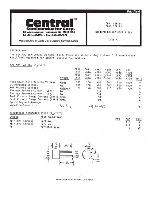

MBR1100Preferred DeviceAxial Lead Rectifier...employing the Schottky Barrier principle in a large area metal-to-silicon power diode. State-of-the-art geometry features epitaxial construction with oxide passivation and metal overlap contact. Ideally suited for use as rectifiers in low-voltage, high-frequency inverters, free wheeling diodes, and polarityprotection diodes.•Low Reverse Current•Low Stored Charge, Majority Carrier Conduction•Low Power Loss/High Efficiency•Highly Stable Oxide Passivated Junction•Guard-Ring for Stress Protection•Low Forward V oltage•150°C Operating Junction Temperature•High Surge CapacityMechanical Characteristics:•Case: Epoxy, Molded•Weight: 0.4 gram (approximately)•Finish: All External Surfaces Corrosion Resistant and Terminal Leads are Readily Solderable•Lead and Mounting Surface Temperature for Soldering Purposes: 220°C Max. for 10 Seconds, 1/16″ from case•Shipped in plastic bags, 1000 per bag•Available Tape and Reeled, 5000 per reel, by adding a “RL’’ suffix to the part number•Polarity: Cathode Indicated by Polarity Band•Marking: B1100MAXIMUM RATINGSPreferred devices are recommended choices for future use and best overall value.THERMAL CHARACTERISTICS (See Note 2)ELECTRICAL CHARACTERISTICS (T= 25°C unless otherwise noted)Figure 2. Typical Reverse Current {Figure 3. Current Derating (Mounting Method 3 per Note 1)Figure 4. Power Dissipation20102.05.01.0V R , REVERSE VOLTAGE (VOLTS)609000.20.040.020.011201600T A , AMBIENT TEMPERATURE (°C)4.03.02.01.00I F(AV), AVERAGE FORWARD CURRENT (AMPS)1.004.03.02.01.02.0140i F , I N S T A N T A N E O U S F O R W A R D C U R R E N T (A M P S )I I P F (A V ), A V E R A G E P O W E R D I S S I P A T I O N (W A T T S )0.50.20.1708010203040500.10.41.020********* 3.0 4.0 5.00.050.02100, R E V E R S E C U R R E N T ( A )R m 4.02.01020100402001 K400200180, A V E R A G E F O R W A R D C U R R E N T (A M P S )F (A V ){ The curves shown are typical for the highest voltagedevice in the voltage grouping. Typical reverse current for lower voltage selections can be estimated from these same curves if V R is sufficiently below rated V R .Figure 5. Typical Capacitance2040V R , REVERSE VOLTAGE (VOLTS)150504*********C , C A P A C I T A N C E (p F )50100601001070809070609080NOTE 1 — MOUNTING DATA:Data shown for thermal resistance junction-to-ambient (R q JA) for the mounting shown is to be used as a typical guideline values for preliminary engineering or in case the tie point temperature cannot be measured.Typical Values for Rin Still AirMounting Method 1P .C. Board with 1-1/2″ x 1-1/2″copper surface.Mounting Method 3P .C. Board with 1-1/2″ x 1-1/2″copper surface.VECTOR PIN MOUNTINGMounting Method 2NOTE 2 — THERMAL CIRCUIT MODEL:(For heat conduction through the leads)Use of the above model permits junction to lead thermal resistance for any mounting configuration to be found. For a given total lead length, lowest values occur when one side of the rectifier is brought as close as possible to the heat sink.Terms in the model signify:T A = Ambient Temperature T C = Case Temperature T L = Lead Temperature T J = Junction Temperature R q S = Thermal Resistance, Heat Sink to Ambient R q L = Thermal Resistance, Lead to Heat Sink R q J = Thermal Resistance, Junction to Case P D = Power Dissipation(Subscripts A and K refer to anode and cathode sides,respectively.) V alues for thermal resistance components are:R q L = 100°C/W/in typically and 120°C/W/in maximum.R θJ = 36°C/W typically and 46°C/W maximum.NOTE 3 — HIGH FREQUENCY OPERATION:Since current flow in a Schottky rectifier is the result of majority carrier conduction, it is not subject to junction diode forward and reverse recovery transients due to minority carrier injection and stored charge. Satisfactory circuit analysis work may be performed by using a model consisting of an ideal diode in parallel with a variable capacitance. (See Figure 5)Rectification efficiency measurements show that operation will be satisfactory up to several megahertz. For example, relative waveform rectification efficiency is approximately 70 percent at 2 MHz, e.g., the ratio of dc power to RMS power in the load is 0.28 at this frequency,whereas perfect rectification would yield 0.406 for sine wave inputs. However, in contrast to ordinary junction diodes, the loss in waveform efficiency is not indicative of power loss: it is simply a result of reverse current flow through the diode capacitance, which lowers the dc output voltage.PACKAGE DIMENSIONSCASE 59-10ISSUE SAXIAL LEAD, DO-41DIM MIN MAX MIN MAX MILLIMETERSINCHES A 4.10 5.200.1610.205B 2.00 2.700.0790.106D 0.710.860.0280.034F −−− 1.27−−−0.050K25.40−−−1.000−−−NOTES:1.DIMENSIONING AND TOLERANCING PER ANSI Y14.5M, 1982.2.CONTROLLING DIMENSION: INCH.3.59−04 OBSOLETE, NEW STANDARD 59−09.4.59−03 OBSOLETE, NEW STANDARD 59−10.5.ALL RULES AND NOTES ASSOCIATED WITH JEDEC DO−41 OUTLINE SHALL APPLY6.POLARITY DENOTED BY CATHODE BAND.7.LEAD DIAMETER NOT CONTROLLED WITHIN F DIMENSION.ON Semiconductor and are registered trademarks of Semiconductor Components Industries, LLC (SCILLC). SCILLC reserves the right to makechanges without further notice to any products herein. SCILLC makes no warranty, representation or guarantee regarding the suitability of its products for any particular purpose, nor does SCILLC assume any liability arising out of the application or use of any product or circuit, and specifically disclaims any and all liability, including without limitation special, consequential or incidental damages. “Typical” parameters which may be provided in SCILLC data sheets and/or specifications can and do vary in different applications and actual performance may vary over time. All operating parameters, including “Typicals” must be validated for each customer application by customer’s technical experts. SCILLC does not convey any license under its patent rights nor the rights of others.SCILLC products are not designed, intended, or authorized for use as components in systems intended for surgical implant into the body, or other applications intended to support or sustain life, or for any other application in which the failure of the SCILLC product could create a situation where personal injury or death may occur. Should Buyer purchase or use SCILLC products for any such unintended or unauthorized application, Buyer shall indemnify and hold SCILLC and its officers, employees, subsidiaries, affiliates, and distributors harmless against all claims, costs, damages, and expenses, and reasonable attorney fees arising out of, directly or indirectly, any claim of personal injury or death associated with such unintended or unauthorized use, even if such claim alleges that SCILLC was negligent regarding the design or manufacture of the part. SCILLC is an Equal Opportunity/Affirmative Action Employer.PUBLICATION ORDERING INFORMATIONJAPAN : ON Semiconductor, Japan Customer Focus Center 2-9-1 Kamimeguro, Meguro-ku, Tokyo, Japan 153-0051Phone : 81-3-5773-3850。