阵列感应(MIT)讲课
- 格式:ppt
- 大小:4.45 MB
- 文档页数:146
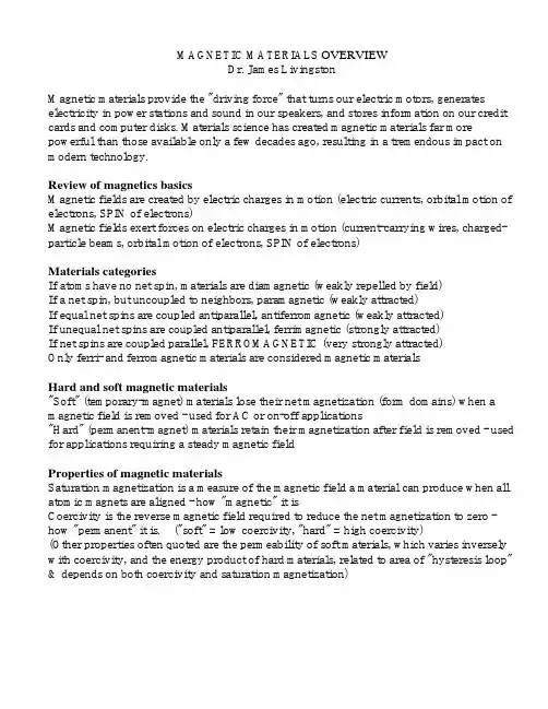
MAGNETIC MATERIALS OVERVIEWDr. James LivingstonMagnetic materials provide the "driving force" that turns our electric motors, generates electricity in power stations and sound in our speakers, and stores information on our credit cards and computer disks. Materials science has created magnetic materials far more powerful than those available only a few decades ago, resulting in a tremendous impact on modern technology.Review of magnetics basicsMagnetic fields are created by electric charges in motion (electric currents, orbital motion of electrons, SPIN of electrons)Magnetic fields exert forces on electric charges in motion (current-carrying wires, charged-particle beams, orbital motion of electrons, SPIN of electrons)Materials categoriesIf atoms have no net spin, materials are diamagnetic (weakly repelled by field)If a net spin, but uncoupled to neighbors, paramagnetic (weakly attracted)If equal net spins are coupled antiparallel, antiferromagnetic (weakly attracted)If unequal net spins are coupled antiparallel, ferrimagnetic (strongly attracted)If net spins are coupled parallel, FERROMAGNETIC (very strongly attracted)Only ferri- and ferromagnetic materials are considered magnetic materialsHard and soft magnetic materials"Soft" (temporary-magnet) materials lose their net magnetization (form domains) when a magnetic field is removed - used for AC or on-off applications"Hard" (permanent-magnet) materials retain their magnetization after field is removed - used for applications requiring a steady magnetic fieldProperties of magnetic materialsSaturation magnetization is a measure of the magnetic field a material can produce when all atomic magnets are aligned - how "magnetic" it isCoercivity is the reverse magnetic field required to reduce the net magnetization to zero - how "permanent" it is. ("soft" = low coercivity, "hard" = high coercivity)(Other properties often quoted are the permeability of soft materials, which varies inversely with coercivity, and the energy product of hard materials, related to area of "hysteresis loop" & depends on both coercivity and saturation magnetization)History of hard (permanent-magnet) materialsLodestones - natural magnets based on magnetite (Fe3O4)Carbon steel (Fe-C) 18th-c. England (horseshoe shaped or bar magnets)Alloy steel (Fe-C+W, Mo, Cr, Co, etc.) - 19th and early 20th-c. (horseshoe or bar)Alnico (Fe+Al,Ni,Co) - 1930s & 1940s - helped Allies win World War IIHard Ferrite (Ba-Fe-O or Sr-Fe-O) - 1950s & 1960s - higher coercivity, cheap!Rare Earth (Sm-Co, Nd-Fe-B) - 1970s-1990s - VERY powerful, but NOT cheap Applicationsmagneticmaterials are used in applications requiring a steady (permanent)Hardmagnetic field. Recent increases in coercivity (resistance to demagnetization) and energy product (dependent on both coercivity and saturation magnetization, and related to the area within the hysteresis loop) have greatly increased the use of permanent magnets in modern technology. The widest applications are in motors, speakers, and sensors, but large quantities of Nd-Fe-B magnets are also used in permanent-magnet MRI systems, each of which uses about 2 tons of permanent magnet.For most applications, the amount of permanent magnet required is inversely proportional to the energy product. Available energy products have increased by a factor of fifty since the 1930s, allowing a corresponding decrease in the size of the magnet, and thus the size of the device. (e.g., small motors made possible by Nd-Fe-B magnets spin the disks and move the heads in computer disk drives, and small speakers produce music in the tiny earphones of i P ods and the like.)At least as important have been increases in coercivity by even greater factors, which allow a greater flexibility of magnet shape. Low-coercivity steel magnets required long bar magnets or horseshoe shapes to minimize demagnetization from reverse fields produced by the north and south poles at the ends of the magnet. (Before the advent of alnico magnets in the 1930s, telephone receivers were long and separate from the speakers because they included a long horseshoe-shaped steel magnet.)Materials for magnetic recording have also improved dramatically in recent years. The first magnetic recorder, patented in 1898, used steel piano wire. Magnetic tapes employing particles of iron oxide coated on plastic tapes were developed in Germany in the 1930s. Such tapes were used in the first commercial computers in the 1950s, and advanced versions remain in use today for audio and video applications, but today's computers instead store information in patterns of north and south poles on disks coated with thin films of cobalt-rich alloys.There have also been dramatic improvements in the properties of soft magnetic materials. Decreases in coercivity have decreased the energy losses of soft materials in ac applications, as have increases in electrical resistivity. Many transformers today useamorphous Fe-rich alloys, cooled so rapidly from the melt that they are unable to crystallize. An area of extensive current research is materials for recording heads, and improved materials have contributed to the remarkable increases in the density of information storage (bits per square inch).。
100Kbps阵列感应MIT5530仪器刻度及测井操作流程一、刻度过程1、首先确认仪器的类型:如100K的仪器为MIT5530,430K的仪器为、MIT6532。
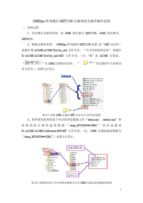
2、根据仪器的类型,100Kbps阵列感应MIT5530仪器的“MIT动态库”放置在X:\ACME\ACME\Tool\hy_mit文件夹里,“半空间刻度理论库”放置在X:\ACME\ACME\Tool\hy_mit\MIT文件夹里。
(注:“X”是ACME安装盘,“”为100K仪器的动态库、“”为仪器的半空间理论库文件夹。
)如图1-1所示。
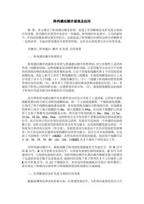
图1-1 放置100K仪器的MIT动态及半空间库流程图3、把所要用的刻度盘子对应的理论数据文件“dataij.mit 、dataij3.mit”和所要刻度仪器的温度数据“temp_HYMIT###.DEC”同时放置到D:\ACME\ACME\Calibration\HYMIT文件夹里。
(注:100K仪器的温度数据为“temp_HYMIT###.DEC”)如图1-2所示。
图1-2 放置刻度盘子对应的理论数据文件及100K仪器的温度数据流程图4、然后点击测井主控软件“”进入主控界面后,点击“”然后出现“创建测井工程”窗口,在窗口里的测井工程名中输入一个名字。
然后点击【确定】。
进入ACME主控制台界面。
依次进入所对应工程名下的ACME主控制台;然后在【测井工程】菜单下用鼠标右击【测井作业】会出现【添加作业】和【浏览工程】两个菜单项。
然后点击【添加作业】菜单项。
点击“”进入新建服务表窗口,选择100K 仪器的服务表,其操作步骤如图1-3至1-7所示。
图1-3 建立测井工程图1-4 建立测井工程服务表1图1-5 建立服务表2图1-6 关闭此窗口图1-7 建立服务表3图1-8 建立网络连接图1-9 进入测井状态5、MIT刻度过程第1步:刻度前准备工作图1-10 进入刻度界面第2步:无环刻度在刻度步骤里选择【无环】后,点击【采样开始】、【采样有效】、【采样结束】。
阵列感应测井原理及应用摘要:本文探讨了阵列感应测井原理,论述了在判断地层水矿化度方面的应用效果,阵列感应在使用中也存在一些缺陷,阵列感应在处理中,人为因素较大,不同的参数处理结果差异较大,这就造成了阵列感应在使用过程中对解释有一定的误导,引起对阵列感应可靠性的怀疑,这在以后的处理方法中有待改进。
关键词:阵列感应测井矿化度应用效果一、阵列感应测井原理简介阵列感应测井的最基本原理与普通感应测井原理类似,但它在硬件上采用简单的三线圈系结构,这种线圈系没有硬件聚焦功能,它采用数学方法对呈不对称形状的纵向响应曲线进行软件聚焦处理。
它由7组接收线圈对和1个共用的发射线圈组成,实际上相当于具有7种线圈距的三线圈系。
在接收线圈系的设计上充分考虑了以下几个问题:(1)、消除直藕信号;(2)、三线圈子阵列纵向特性的频率响应没有盲频;(3)、要有若干子阵列分别反映浅部和深部地层信息;(4)、各接收子阵列之间的间距应按一定规律变化和分布;(5)、离发射线圈较远的接收子阵列应考虑发射功率和接收信号的强度。
高分辨率阵列感应测井仪在硬件设计时充分考虑了上述因素,它的每个接收线圈系都由两个相互对称的线圈组成,即一个主接收线圈和一个辅助接收线圈,它利用了两个线圈电磁场叠加原理,来实现消除直藕信号影响的目的。
在线圈系的排列上设计了最小线圈距为6in,最大线圈距为94in,在这两个线圈距之间采用了近似于指数形式的线圈系分布,即全部子阵列间距为6in、10in、15.7in、24.5in、38.5in、60in、94in。
这种排列方式不仅有利于采集浅部地层和深部地层信号,而且有利于径向有效信息的均匀采样。
发射信号是加到一个单独的发射线圈上的,这种方法能使发射器的有效功率变为最大,由发射线圈发射出的是一个形状为方形的电压波形(即方波),发射波采用方波是由于其具有较高的发射频率,对于给定的电压能使发射线圈的功率变为最大。
而且它具有宽的频谱,它包括了方波频率(约等于10KHZ)及所有的奇次谐波的能量,因此每个线圈可以在10、30、50、70、90、110、130、150KHZ共8个频率下同时进行工作。
MIT高分辨率阵列感应测井1 引言随着油气勘探程度的不断深入,勘探对象也变得越来越复杂,常规测井技术已无法很好的解决存在的问题。
高分辨率阵列感应测井技术的诞生,较好的解决了常规测井仪器存在的纵向分辨率低、探测深度浅且不固定、不能解决复杂的侵入剖面等问题。
吐哈油田自引入高分辨率阵列感应测井来,在各个区块得到了应用,并取得了良好的地质应用效果。
2 阵列感应测井原理及仪器简介阵列感应测井基本思路与横向测井一脉相承,它采用一系列不同线圈距的线圈系测量同一地层,从而得出原状地层及侵入带电阻率等参数。
所不同的是阵列感应测井采用先进的电子、计算机技术及数字处理等先进方法,通过多路遥测短节,把采集的大量数据送到地面,再经过计算机进行处理,得出具有不同探测深度和不同纵向分辨率曲线。
与双感应、浅聚焦测井不同,阵列感应测井除得出原状地层和侵入带电阻率外,还可以研究侵入带的变化,确定过渡带的范围。
根据获得的基本数据进行二维电阻率径向成像和侵入剖面的径向成像。
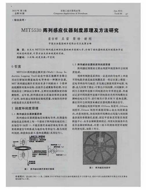
以阿特拉斯公司的MIT测井仪器为例,MIT高分辨率感应测井仪采用三线圈系结构(一个发射,两个接收基本单元)(图1)。
线圈系由七个接收阵列组成,共用一个发射线圈,采用八种频率同时工作,共测量112个原始实分量和虚分量信号,传输到地面经计算机处理,实现软件数字聚焦,获得三种纵向分辨率、六种探测深度的测井曲线。
经过处理可以得到具有3种不同纵向分辨率和6种不同径向探测深度的测井曲线;运用一维、二维反演技术,可以反演出地层真电阻率Rt、冲洗带电阻率Rxo及侵入深度,可对储层进行径向侵入特征的定量描述。
3阵列感应测井优越性及处理随着油气勘探程度的逐渐加深和难度的加大,要求测井不但要具有较高的纵向分辨率和径向探测深度,在三维空间中能探测到更多的地层信息,而且能胜任非均质地层和薄储层的测井地质精细解释。
电阻率测井仪器是目前探测半径最大的测井仪器,其它测井仪器很难探测到原状地层的情况。
