Fender Guitar Amps Manual Fender 65 Twin Reverb Manual
- 格式:pdf
- 大小:498.02 KB
- 文档页数:7

WARNING: Never carry your paintball marker uncased when not on a playing field. The non-playing public and law enforcement personnel may not be able to distinguish be-tween a paintball marker and a firearm. For your own safety and to protect the image of the sport, always carry your marker in a suitable marker case or in the box in whichit was shipped.CAUTION: Paintballs may remain in the feed tube system after the loadersection is empty. Always check for paintballs in the feed tube and breech toprevent accidental discharge!3.1 3.23.3 3.4adapter). The D*Fender’s ASA is located3.5 WARNING:Insert the threaded end of the air cylinder• Remember compressed air and nitrogen systems cylinders can be extremelydangerous if misused or improperly handled. Use only cylinders meetingD.O.T., TC or regionally defined specifications.• Never disassemble your tank or tank regulator. Only a qualified and trainedtechnician should perform work on your tank and tank regulator.• Never add any lubricants or greases into the fill adapter on yourtank regulator.WARNING: Before switching your D*Fender marker On. Make sure it ispointed in a safe direction. Everyonewithin firing range should always use paintball approved eye and face protectionin the presence of live paintball mark-ers. Make sure the marker is set to “SafeMode”, before following the steps below.ing device. Remember that the ultimate safety device is you, the operator. 4.1FLASH FREQUENCY FlickerFast Flash Slow Flash Solid Glow Breech Sensor is ON, Ball is sensed Breech Sensor is ON, No Ball is sensed Breech Sensor is turned OFF Breech Sensor is malfunctioning/eyes dirty BREECH SENSOR STATUS LED SAFE COLORBlue GreenBattery level is good Replace batteryBATTERY LEVELPOSITION 321Safe Green or Blue Safe Red Semi-Auto Amber Burst Purple Full-AutoLED COLOR FIRING MODEWARNING: Check the velocity every time prior to using your D*Fender marker. The velocity can be adjusted via the Velocity Adjuster (fig 5.1) which is accessible through either side of the marker. Adjust the velocity with a 3/32” hex wrench by inserting it into the adjuster holes and rotating.velocity is achieved. A paintball specificincrease the input pressure, and outwardWARNING: Do not increase regulator pressure over 200psi or it will damage the marker.5.15.2The (2) second set screw adjusts the rearctivation point. For best results,the activation point should be set right inthe middle of the total Trigger movementIf any of the set screws are over adjusted5.31. Start with the Ramp in the OFF position(fully toward the back of barrel, Fig 5.4).Go to your fields shooting range or other 5.4LEDSolid AquaSolid PurpleSolid WhiteFlickering RedFlickering Green Solid AmberSolid BlueSolid GreenSolid RedFiring Mode Max Rate of Fire Dwell Trigger De-bounce Ball In Place Time Ramp Start Ramp Sustain Burst Shot Count Calibrate Selector SETTING # OF BLINKS 54321Semi Auto Burst Ramp Full Auto Select Fire FIRING MODEPOSITION 321Safe Green or Blue SafeRed Semi-Auto Amber Burst PurpleFull-AutoLED COLOR FIRING MODE BLINKS VALUE VALUE BLINKS # OF BPS BPS # OF 513.5614.0714.5413.0312.5212.0111.58.088.599.0109.51110.01210.51311.014BLINKS VALUE VALUE BLINKS # OF BPS BPS # OF 1920.01819.51719.01618.51518.015.02115.52216.02316.52417.0252017.5BLINKS IN MS IN MS BLINKS # OF DWELL DWELL # OF 59.069.57810.048.538.027.517.03.093.5104.0114.5125.0135.5146.06.515the user to lock the settings mode, which WARNING: Once you are done using your D*Fender it is extremely important thatyou fully unload the marker of all paintballs and compressed air. Never look down the barrel unless it’s removed from the marker.6.1CAUTION: Paintballs may remain in the feed tube system after the loadersection is empty. Always check for paintballs in the feed tube and breech to prevent accidental discharge!WARNING: Before attempting to perform any disassembly or maintenance on your D*Fender marker, make sure that all paintballs and air sources have been removed from the marker and that the regulator gauge reads 0 psi. Install a barrel blocking device, move the Selector Switch to the Safe position and powerthe marker Off.WARNING: Do not rinse the D*Fender under water, as you may damage the marker’s electronics. WARNING: Once the Side covers are removed the Eyes and Detents may be loose and can fall out of the internal assembly.Buttons and slide the Top Rail toward the rearof the marker about an inch (2.5 cm) and lift8.1WARNING: Before removing the Quick Strip Pins from marker. Confirm the marker is degassed and the gauge reads 0 psi.Push the pins with finger or hex wrench fromOnce the Quick Strip Pins are removed, thecurved end plugs correctly into the feed tubeWARNING:• Before the Internal Assembly can be removed, the Side Covers, Top Rail, Quick Strip Pins, Barrel, and Feed Ramp must be removed first.• Before removing the Internal Assembly, make sure the Eyes are still properly within the Body to prevent damaging the eye harness. Using two hands place one finger in the8.28.38.4WARNING: The Internal Assembly must be removed prior to splitting the shells. See page 15 for removal instructions.WARNING:Never carry your Marker uncased when not on a playing field. The non-playing public and law enforcement personnel may not be able to distinguish between a paintball marker and firearm. For your own safety and to protect the image of the sport, always carry your Marker in a suitable marker case or in the box in which it was shipped. When you are finished using your Marker it is important that you prepare it for storage. This will not only serve to increase the life of the marker, but will assure optimum performance on your next outing.unauthorized persons.CAUTION: Paintballs may remain in the feed tube system after the loader section is empty. Always check for paintballs in the feed tube and breech to prevent accidental discharge!11. DIAGRAMS/PARTS LISTDIAGRAM #PART DESCRIPTION SKU 1STANDARD ALU BARREL72720 2ALU BARREL INSERT- SIZE .69011523 2ALU BARREL INSERT- SIZE .68511522 2ALU BARREL INSERT- SIZE .68011521 3O-RRING BUNA-N70 DUR-018 (.739 ID)72508 4O-RING BUNA-N 70 DUR 1MM CS X 19.5MM ID72488 5APEX BARREL72721 6O-RING BUNA-N 70 DUR -021 (.926 ID)11506 7APEX WIRE SPRING11504 8APEX BODY INSERT TOP11500 9APEX HOUSING TUBE11502 10APEX ADJUSTER11505 11APEX DEFLECTOR11503 12APEX BODY INSERT BOTTOM11501 13MAIN SPRING17535 14BOLT RUBBER TIP17533 15BOLT17532 16O-RING BUNA-N 70 DUR -017 (.676 ID)17534 17BOLT GUIDE72722 18O-RING BUNA-N 70 DUR 2.5MM CS X 23.0MM ID72340 19POPPET SEAL17629 20POPPET ASSEMBLY WITH SPRING17539 21POPPET SPRING17623 22VELOCITY ADJUSTER72723 23O-RING BUNA-N 70 DUR 2.4MM CS X 10.80MM ID17538 24O-RING URETHANE 90 DUR 2MM CS X 10MM ID 17540 25DOWEL PIN .125 DIA X .37572724 26O-RING BUNA-N 70 DUR 1.5MM CS X 12MM ID 17537 27SCREW BHCS 6-32 X .250 (SMALL HEAD)17652 28RELEASE BLOCK72725 29SPRING .120OD X 0.50FL .020WD RATE 18.LB/IN72584 30RELEASE BUTTON72726 31BEARING BALL 1/8 DIA 72585 32AIR TRANSFER GASKET17530 33MANIFOLD7272735O-RING BUNA-N 70 DUR 0.8MM CS X 12.0MM ID17553 36AIR TRANSFER TUBE MALE17551 37SOLENOID 17528 38CHECK VALVE17531 39MAIN CURCUIT BOARD72728 40EYE HARNESS72729 41BALL DETENT72577 42BODY72730 43SCREW SET 10-32 X .375 CP72654 44REGULATOR DISK17591 45REGULATOR PISTON72360 46REGULATOR PISTON RETURN SPRING72395 47O-RING BUNA-N 70 DUR -008 (.176 ID)10761 48TUBE LOWER72731 49O-RING BUNA-N 70 DUR -012 (.364 ID)72490 50SCREW SET 10-32 X 1.250 CUP POINT72732 51REGULATOR MOUNT72733 52REGULATOR FILTER COVER72359 53O-RING BUNA-N 70 DUR 1.5MM CS X 6.5MM ID72509 54REGULATOR FILTER72358 55REGULATOR BODY72734 56REGULATOR SEAL72364 57O-RING URETHANE 70 DUR -012 (.364 ID)10257 58REGULATOR ON/OFF PIN72372 59REGULATOR NUT72599 60O-RING BUNA-N 70 DUR -006 (.114 ID)72489 61REGULATOR SEAL RETAINER72652 62PIN REGULATOR72363 63REGULATOR LEVER72613 64PIN WEDGE72614 65REGULATOR CAM SPRING72369 66SCREW SHSS 3/16 DIA 3/8 LG 8-32 x .25072512 67300PSI EMPIRE GAUGE72375 68REGULATOR OPP COMPLETE17597 69MAIN REGULATOR SPRING72608 70REGULATOR CAP7261572O-RING BUNA-N 70 DUR -020 (.864 ID)40920 73CATCH CUP72736 74BEARING .250 ID X .500 OD X .125 THK38803 75E-RING 38823 76SPROCKET 31074 77GEAR BOX COVER38496 78SCREW PHCS 4-40 X .625 38827 79SENSOR COVER38497 80DRIVE SENSOR72737 81O-RING BUNA-N 70 DUR -028 (1.375 ID)38820 82PULLEY GEAR38837 83MOTOR WITH WIRING HARNESS72738 84GEAR PIN - DOWEL PIN .078 DIA X .50038828 85DRIVE SHAFT72739 86NUT HEX 4-4038805 87CARRIER72740 88SCREW THCS 6-32 X .37538982 89SPRING .180OD X 1.500FL .026WD RATE 8.0LB/IN72741 90BUTTON RELEASE72742 91TOP RAIL72743 92RIGHT SHELL72744 93SIDE RAIL ADAPTER72745 94SIDE RAIL72746 95SCREW SHCS 6-32 X .437572747 96CONNECTER BOARD SCREW W/ WASHER72779 97HARNESS CIRCUIT BOARD (COMPLETE)72749 98DOOR RETAINER38938 99SPRING .114OD X .31FL .014WD RATE 9.6LB/IN38939 100DOOR SWITCH38937 101RIGHT SIDE COVER72750 102LID SPRING31025 103STANDARD LID72751 104QUICK LOAD LID 72752 105MAGNET 8MM DIA .X 4MM31009 106MAGNET 8MM DIA X 6MM38475 107BATTERY DOOR72753109HOLDER BATTERY AA38804 110BATTERY HARNESS HOLDER17823 111BATTERY HARNESS17715 112FEED RAMP BACK72755 113TRIGGER72756 114SCREW SET 6-32 X .250 FLAT POINT17523 115SPRING .180OD X .310FL .012WD RATE 3.0LB/IN 72757 116BEARING .156 ID X .3125 OD X .155572381 117SCREW SHSS 5/32 DIA 5/16 LG 6-32 X .13872758 118FEED RAMP FRONT72759 119SPRING PIN .0625 DIA X 1.00072760 120FEED RAMP TOP72761 121SCREW SHCS 6-32 X .312572762 122LID RETAINER72763 123SCREW SHCS 6-32 X .75017815 124TRIGGER GUARD72764 125SELECTOR CIRCUIT BOARD72765 126SWITCH SHAFT INNER WITH MAGNET72766 127SELECTOR SPRING72767 128NUT HEX 6-32 .25 WIDE x .092 THK72768 129FOREGRIP RH72769 130FOREGRIP LH72770 131SCREW SHCS 6-32 x .87572771 132COMPLETE SHELL SPRING PIN (SHORT)72772 133LEFT SIDE COVER72773 134POWER BUTTON17712 135LIGHT PIPE17710 136SCREW FHCS 4-40 X .50017650 137SELECTOR SWITCH OUTER72774 138SCREW BHCS 6-32 X .25017653 139SCREW FHCS 6-32 X .75072775 140SLING MOUNT72776 141LEFT SHELL 72777 142COMPLETE SHELL SPRING PIN (LONG)71933 143RUBBER GRIP17717 144O-RING BUNA-N 70 DUR 1.0mm CSx6.0mm ID72546。
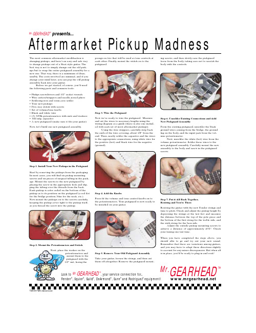
Aftermarket Pickup Madness Mr.GEARHEAD™presents...The most common aftermarket modification is changing pickups, and here’s an easy and safe way to change pickups out of a Strat-style guitar. The best way is not to simply change out the old pick-ups but to swap the entire pickguard assembly for a new one. That way, there is a minimum of disas-sembly. The costs involved are minimal, and if you change your mind later, you can pop the old pickup assembly back into your guitar.Before we get started, of course, you’ll need the following parts and common tools:• Philips screwdrivers and 1/2” socket wrench• Wire cutters/strippers and needle-nosed pliers • Soldering iron and rosin-core solder• Your new pickups• Five-way switch with screws• Set of volume/tone knobs• Black and white wire• (3) 3250k potentiometers with nuts and washers • .022 mfg. capacitor• A new pickguard (make sure it fits your guitar) Now, let’s build our new pickguard assembly.Step 1. Install Your New Pickups in the Pickguard Start by removing the pickups from the packaging. In most cases, you will find six pickup mounting screws and six pieces of surgical tubing in the pack-age. Mount the screws to the new pickguard by placing the screw in the appropriate hole and slip-ping the tubing over the threads from the back. Each pickup is color coded on the bottom of the pickup as to its position on the pickguard (a red dot for the bridge position, blue for the neck, etc.). Now mount the pickups on to the screws carefully, keeping the pickup cover tight to the pickup itself, as you thread the screw into the pickup.Step 2. Mount the Potentiometers and SwitchNext, place the washer on thepotentiometers andmount them to thepickguard with the1/2” nut, facing the prongs on two that will be used as tone controls ateach other. Finally, mount the switch on to thepickguard.Step 3. Wire the PickguardNow we’re ready to wire the pickguard. Measureand cut the wires to necessary lengths using thewiring diagram as a guide (there is also one includ-ed with each set of most aftermarket pickups).Using the wire strippers, carefully strip backthe ends of the wire covering, about 1/8” from theend. Then, neatly solder the capacitor and the wiresto the appropriate connections, using white wire forthe positive (hot) and black wire for the negative(ground).Step 4. Add the KnobsPress fit the volume and tone control knobs on tothe potentiometers. Your pickguard is now ready tobe installed on your guitar.Step 5. Remove Your Old Pickguard AssemblyTake your guitar, loosen the strings, and then cutthem off altogether. Remove the pickguard mount-ing screws, and then slowly ease the pickguardloose from the body, taking care not to scratch thebody with the controls.Step 6. Unsolder Existing Connections and AddNew Pickguard AssemblyFrom the existing pickguard, unsolder the blackground wires coming from the bridge, the groundlug on the body, and the input jack from the vol-ume potentiometer.Next, unsolder the white (hot) wire from thevolume potentiometer. Solder these wires to thenew pickguard assembly. Carefully mount the newassembly to the body and screw in the pickguardscrews.Step 7. Put it All Back Together,Restring and You’re ThereRestring the guitar with the new Fender strings andtune to pitch. Check and adjust the pickup height bydepressing the strings at the last fret and measurethe distance between the top of the pole piece andthe bottom of the first string for the treble side, andthe sixth string for the bass side.Adjust the outside pickup mounting screws toachieve a distance of approximately 4/32”. Checkyour tuning one last time.When you have completed the steps above, youshould able to go and try out your new sound.Remember that there are variations among guitars,and you may have to adapt these directions slightlyto account for any minor discrepancies. But when allis in place, you’ll be ready to plug in and rock!Mr.GEARHEAD™ Look to Mr.GEARHEAD™, your service connection for...Fender®, Squier®, Guild®, DeArmond®, Sunn®and Rodriguez®equipment!©2000 FMIC Advertorial。

Fender Musical Instruments7975 North Hayden Road, Scottsdale, Arizona 85258 U.S.A.Since 1946, Fender realized the importance of your amplifier. You see, your amplifier is more than just a combination of dials, wires and speakers. It is a finely tuned musical instrument. And like any fine musical instrument, it should be treated with special care and attention to detail.At Fender, we know what building guitar amplifiers is all about. For over half a century, we have been designing and producing some of the world's best amplifiers, helping shape the face of music. In fact, many of the world's most classic and best sounding amplifiers have proudly worn the Fender name.Whether you're after that classic Fender tone, a clean crisp sound for your Bass or Keyboard or the raw driving power of modern distortion, your decision to purchase a Fender amplifier is one you will appreciate with each passing note for years to come.Wishing you years of enjoyment and a heartfelt thank you,Bill SchultzBill SchultzChairmanFender Musical Instruments CorporationSensitivity Switch -Automatically adjustsyour amp’s sensitivity forSingle Coil or Humbucking PickupsT input jacks. The footswitch circuitry allows for remote selection of both the 5th preset (a lead or solo sound)and Chorus. Moreover, the Tape/CD input jacks and the 1/4 inch headphone jack make your Automatic the perfect amp for practice or small “single” gigs.Take the time to get to know each other... Tune-up,Plug-in and ... Play On!WARNING:-TO PREVENT DAMAGE, FIRE OR SHOCK HAZARD, DO NOT EXPOSE THIS UNIT TO RAIN OR MOISTURE.-NO USER SERVICEABLE PARTS INSIDE, REFER SERVICING TO QUALIFIED PERSONNEL ONLY .-THIS UNIT MUST BE EARTH GROUNDED.YOUR AUTOMATIC AMPLIFIER3A. INPUT- Plug your guitar in here.- Sensitivity/ gain switch for the input signal.reducing distortion in the clean settings when using guitars with active electronics or humbucking pickups. The normal ‘out’ position is set for single coil pickups.- This button activates the classic FENDER-- This button activates the STUDIO-CLEANupper mid to high frequency range and providesslightly more overall gain than the Fender-Cleanpreset.- Thisrearranges the gain/tone structure to produce asemi-distorted tone useful for playing rhythm orbluesy leads. This preset has slightly more overallloudness than the clean presets.- Thisfurther modifies the structure to provide more gain,loudness and a different tonal response than therhythm/crunch preset.Note: To create even more tonal possibilities, you cancombine the various presets by simply pressing twoor more preset buttons (items C through F)simultaneously.G. FTSW- This LED illuminates when theLEAD/OVERDRIVE preset is activated, either bypressing the corresponding preset button (item H), orby using the CHANNEL SELECT function on theoptional two-button footswitch (see item Q).- Thisis useful for playing full-on leads and heavy powerchords with lots of sustain. It has significantly moredrive and sustain than any of the other presets. Whenthis button is in, the previously selected clean orrhythm preset is disabled. This lead/overdrive soundcan also be activated by the optional footswitch (seeitem Q).I. VOLUME- Adjusts the overall loudness of theamplifier.J. TREBLE- Adjusts the amount of boost or cut inthe high frequency range for all presets.K. BASS- Adjusts the amount of boost or cut in thelow frequency range for all presets. AUTOMATIC FRONT CONTROL PANEL4L. REVERB - Adjusts the amount of reverberation for all presets.M. CHORUS INDICATOR - This LED illuminates when the chorus circuit is active. The LED brightness varies indicating the chorus sweep rate.N. CHORUS - This control automatically adjusts both the depth and sweep rate of the chorus circuitry. A lower setting produces a slow, full-range sweep whereas a higher setting produces a fast and less wide sweep.O. CHORUS SWITCH - Activates the chorus circuitry for all presets. Chorus can also be activated by the optional footswitch (see item Q).P. TAPE/CD INPUTS -Plug-in connection for any line level stereo or mono signal to be mixed together with the instrument signal. These inputs have fixed gain and are unaffected by any of the front panel controls. They can be used to connect a tape or CD player, or other signal source (rhythm machine, synth…) to be used as accompaniment for practice or performance. The output level control of the external signal source is used to control its volume while the front panel VOLUME control is used for the instrument to obtain a balance.Q. FOOTSWITCH - Plug-in connection for the optional remote footswitch (P/N 029972) to select the lead/overdrive preset, and to switch the chorus on and off. For proper footswitch operation, both the LEAD/OVERDRIVE switch (item H) and the CHORUS switch (item O) must be in the ‘out’ position. NOTE: Any good quality patch cord will work with the remote footswitch, however an unshielded speaker type cord is preferable to a coax guitar cord.R. HEADPHONES - This jack provides an output to standard mono or stereo headphones for private listening. It can also be used as an unbalanced line output. Use of this jack automatically disables the speaker. CAUTION: Prolonged listening at high levels may be hazardous to your hearing!S. POWER INDICATOR - This LED illuminates when your Automatic is receiving power.T. POWER SWITCH - Turns the AC power ON and OFF. When the switch is OFF, the amplifier is completely shut down.LINE CORD - This amplifier is equipped with a grounding type supply cord to reduce the possibility of shock hazard. Be sure to connect it to a grounded AC receptacle. The line cord should be connected to a suitable power source in accordance with voltage and frequency as shown in the power rating on the rear panel.DO NOT ALTER THE THREE PRONG PLUG.5If the amp is set up but does notfunction, check the following items:• Is the power cord properly plugged into an electrical outlet?• Is there power at the outlet?• Are all the control knobs turned above 0?• Is the volume control on the instrument turned up?• Is the instrument properly plugged into the amplifier?(Eliminate any effects pedals and try using another cord.) If after checking all of the above your amplifier is still not performing correctly, consult your authorized Fender Service Center.The exclusive covering on yourFender Automatic cabinet has beenespecially designed for years oflasting beauty. A very light soapysolution on a sponge may be used toremove dirt and residue that may accumulate in the fabric. Be careful not to let any liquid come in contact with operating surfaces. REMEMBER TO UNPLUG THE POWER CORD BEFORE CLEANING AND WAIT UNTIL THE UNIT IS COMPLETELY DRY BEFORE PLUGGING IT IN.TROUBLESHOOTINGCOVERING CARE6SPECIFICATIONSTYPE: PR 329PART NUMBER:MODEL GT MODEL SE22-6300 (120V)22-6400 (120V)22-6330 (240V) Aust22-6430 (240V) Aust22-6340 (230V)UK22-6440 (230V) UK22-6360 (230V) Eur22-6460 (230V) Eur22-6370 (100V)22-6470 (100V)POWER REQUIREMENTS:100V AC, 50/60 Hz 90W120V AC, 60 Hz, 90W230V AC, 50 Hz, 90W240V AC, 50 Hz, 90WPOWER OUTPUT:25W into 8Ωat 5% THDINPUT IMPEDANCE :Instrument: >500 kΩTape/CD: 12 kΩNOMINAL INPUT LEVEL: Instrument: 100 mVINPUT SENSITIVITY: Tape/CD: 120 mV for clippingSPEAKER:One Fender Special Design 12” speaker(P/N 025923)FOOTSWITCH: 2 Button Footswitch,(Optional)Controls Gain Select and Chorus(P/N 029972)DIMENSIONS:Height: 17.5 in 44 cmWidth:17 in 43 cmDepth:9.5 in 24 cmWEIGHT: 28 lbs 12.7 kgFender®, Tone-Master®and Princeton®Chorus are registeredtrademarks of FMIC.Product specifications are subject to change without notice.7BLOCK DIAGRAMA PRODUCT OF:FENDER MUSICAL INSTRUMENTS CORP.CORONA, CA 91720 USA。

Fender的型号编码详细说明小弟根据Fender产品手册翻译的;希望能造福广大F丝..不过本人水平有限;很多朋友肯定比我熟悉Fender的产品;如果有错误和遗漏的地方欢迎指正和补充Fender产品系列旗下所有品牌和产品型号的编号结构以10个数字组成.. XXX-XXXX-XXX举例:011-7702-803A.前三位编号XXX-XXXX-XXX前三位代表Fender电吉他&电贝斯的产地与琴桥配置XXX-XXXX-XXX第一位是表示产品的有无Floyd Rose双摇琴桥n编号0为无Floyd Rose双摇琴桥0XX-XXXX-XXXn编号1为有Floyd Rose双摇琴桥1XX-XXXX-XXX不包括“Fender Time Machine”系列举例:113-4700-306 就是一款双摇电吉他吉他XXX-XXXX-XXX后两位数字代表的是吉他的产地编号n编号13/14代表墨西哥产电吉他&电贝斯n编号10/11/17代表的是美国产电吉他n编号19代表美国产电贝斯注:Highway系列电贝斯产地代码是”11”n编号15代表美国产Custom Shop电吉他&电贝斯n编号25/27代表日本产电吉他&电贝斯主要集中在Classic和Special Edition等系列里;还有部分Artist系列n编号26代表韩国产电吉他&电贝斯主要集中在Special Edition系列里补充:以前韩国Fender都是Cort代工的;现在应该都在印度尼西亚生产;有部分型号为Samick三益印尼工厂代工的..日本Fender工厂目前也关闭了;貌似要全部整合到墨西哥工厂;目前Fender旗下品牌在日本只有一家代工Jackson日产的工厂..第一部分完结B.中四位编号第二部分XXX-XXXX-XXX中四位代表Fender电吉他&电贝斯的型号和基本配置XXX-XXXX-XXX前两位数字代表具体型号;无规律;特定型号特定数字编号..XXX-XXXX-XXX第三位编号代表的是左手款或右手款编号0或其他任意数字代表为右手款电吉他/电贝斯 XXX-XX0X-XXX编号2代表为左手款电吉他/电贝斯 XXX-XX2X-XXX 举例:013-4620 墨西哥产标准系列Stratocaster左手款电吉他XXX-XXXX-XXX最后一位是指指板材料枫木/花梨木/乌木编号0或其他数字代表花梨木指板极少数乌木 XXX-XXX0-XXX编号2代表枫木指板 XXX-XXX2-XXX举例:011-0402 美产标准系列Stratocaste r枫木指板一般所称的白指板011-0400 美产标准系列Stratocaster花梨木指板一般所称的玫瑰木或黑指板010-1680 美产豪华系列Stratocaster 乌木指板C.后三位编号第三部分XXX-XXXX-XXX后三位代表Fender电吉他&电贝斯的配套包装和琴身颜色XXX-XXXX-XXX第一位指有无配置琴盒或琴包编号3代表Gig bag 普通琴包/豪华琴包 XXX-XXXX-3XX编号5代表None无琴包或琴盒;普通纸盒 XXX-XXXX-5XX编号7代表Standard Case 标准琴盒 XXX-XXXX-7XX编号8代表Deluxe Case 豪华琴盒 XXX-XXXX-8XXXXX-XXXX-XXX后两位代表琴身颜色编码原帖由jeanlee于 2011-4-19 11:02 发表那我的N3145859代表什么呢你的那个应该是序列号编码;不是型号编码..序列号编码一般是包含生产日期等信息的;好像Fender官网上有说明的..Fender&Squier 颜色代码及中英文对照_00 3-Color Sunburst 3色渐变_48 Teal Green Transparent 透明兰绿_01 White Blonde 奶白 _49Sea Foam Green 海洋泡沫绿_02 Lake Placid Blue 湖蓝 _50 Special Color 特定型号特定颜色_03 2-Color Sunburst 2色渐变 _51 Sky Blue 天空蓝_04 Daphne Blue 瑞香蓝 _52 Tobacco Sunburst 烟草渐变_05 Olympic White 奥林匹克白 _54Dakota Red 达科他红_06 Black 黑_55 Blizzard Pearl 暴雪珍珠白_07 Vintage Blonde 经典奶黄 _56Shell Pink 贝壳粉红_08 Ocean Turquoise 海洋青绿 _57Surf Green 浪花绿_09 Candy Apple Red 苹果红 _58 Torino Red 都灵红_10 Black with Gold Paisley 黑+苏格兰金涡纹旋花纹_59 Black Pearl 黑珍珠_11 Black with Candy Red Paisley 黑+苏格兰红涡纹旋花纹 _61 Black Cherry Burst 樱桃红渐变黑_13 Blue Sparkle 闪光蓝_62 Blue Transparent 透明蓝_14 Chartreuse Sparkle 闪光黄绿_63 Graffiti Yellow 涂鸦黄_15 Hot Rod Red 热力红_64 Montego Black 蒙特卡洛黑_16 Champagne Sparkle 闪光香槟_66 Burgundy Mist Metallic 金属雾酒红_17 Silver Sparkle 闪光银_67 Honey Blonde 蜜糖金_18 Gold Sparkle 闪光金_68 Gun Metal Blue 金属蓝_19 Sage Green Metallic 金属绿_69 Ultra Marine Blue 海军蓝_20 Amber 琥珀_70 Cadmium Orange 镉橙_21 Natural 原木_71 Candy Green 蜜糖绿_22 Sunset Orange Transparent 透明落日橙_72 Sonic Blue 音速蓝_23 Pearl White 珍珠白_73 Midnight Blue 午夜蓝_24 Inca Silver 印加银_74 Aqua Marine Metallic 金属海军水蓝_25 Chrome Red 铬红_75 Midnight Wine 午夜酒红_26 Violet 紫罗兰_76 Midnight Purple 午夜紫_27 Sapphire Blue Transparent 透明宝石蓝_77 Frost Red 冻霜红_28 Crimson Burst 渐变深红_78 Aztec Gold 阿兹特克金_29 Blue Agave 龙舌兰蓝_79 Frost Gold 冻霜金_30 Cherry Sunburst 樱桃渐变_80 Arctic White 北极白_31 Aged Cherry Sunburst 陈年樱桃渐变 _81 Caramel Metallic 金属淡褐_32 Brown Sunburst 棕色渐变_82 Candy Tangerine 蜜糖橘红_33 Altantic Blue Metallic 金属海洋蓝_83 Ice Blue Metallic 金属冰蓝_34 Aged Natural 陈年原木_84 Copper 铜黄_35 Ebony Burst 乌木渐变_85 Bright Amber Metallic 金属亮琥珀_36 Blue Burst 渐变蓝_86 Bright Sapphire Metallic 金属宝石蓝_37 Antique Burst 陈年古黄渐变_87 Cobalt Blue Metallic 金属艳蓝_38 Crimson Transparent 透明深红_88 Desert Sunset 大漠日落_39 Ebony Transparent 透明乌木_89 Desert Sand 大漠黄_40 Fiesta Red 嘉年华红_90 Baltic Blue 波罗的海蓝_41 Vintage White 复古白_91 Chrome Silver 铬银_42 Honey Burst 蜜糖渐变_92 Walnut 胡桃木纹色_43 Pewter 白蜡_93 Purple Metallic 金属紫_44 Shoreline Gold 黄金海岸_94 Purple Transparent 透明紫_45 Teal Green Metallic 金属兰绿_95 Chrome Blue 铬蓝色_46 Sherwood Metallic 灰绿_96 Orange 橙色_47 Sienna Sunburst 赭色渐变_98 Green 绿色_99 Bronze 赤褐色这个只是琴身的编号不是琴的型号Fender的型号用三串数字来表示:XXX-XXXX-XXX;第一条是产地;第二条是型号;最后一条是配置..010;011:美产Fender;两个编号的原因是出自两家工厂;各自生产不同的型号..013:墨西哥产Fender..025;027:日产Fender..033-6;-1:韩产Squier..033-0:中国产Squier..031;032:印尼产Squier..fender吉他的型号说明fender吉他的型号很多;各位数字都代表不同的意思:如: 013-4600-803前面三位:代表有无floyd rose和产地;第一位指有无floyd rose;0为无1为有后两位指产地;13是墨西哥;10、11指美国中间四位:代表型号第三位0指右手;2指左手第四位0指红木;2指枫木后面三位:配置第一位指吉他盒和吉他包;3指deluxe gig bag;5指无case;7有case; 8指deluxe bag后两位指颜色电吉他硬件:关于 Fender 序列号的秘密墨西哥产FENDER电琴:序号介绍年份单位:年MN1+5或者6位数字 1991-92MN2+5或者6位数字 1992-93MN3+5或者6位数字 1993-94NN4+5或者6位数字 1994-95MN5+5或者6位数字 1995-96MN6+5或者6位数字 1996-97MN7+5或者6位数字 1997-98MN8+5或者6位数字 1998-99MZ0+5或者6位数字 2000MZ1+5或者6位数字 2001日本产FENDER电琴:序号介绍年份单位:年JV+5位数字 1982-84SQ+5位数字 1983-84E+6位数字 1984-87A+6位数字 1985-86;1997-99 B或C+6位数字 1985-86F+6位数字 1986-87G+6位数字 1987-88H+6位数字 1988-89I或J+6位数字 1989-90K+6位数字 1990-91L+6位数字 1991-92M+6位数字 1992-93N;O或P+6位数字 1993Q+6位数字 1993-94S+6位数字 1994T+6位数字 1994-95U+6位数字 1995-96V+6位数字 1996-97B+6位数字 2000P+6位数字 2001日本产FENDER电琴:序号介绍年份单位:年1-6000 1950-1954到100004或者5位;包括前面有0或者带字母 1954-1956从10000开始4或者5位数字;包括前面有0或者字母 1955-1956 10000-200005或者6位数字;包括前面有0或者字母 195720000-300005或者6位数字;包括前面有0或者字母 195830000-40000 195940000-50000 196050000-70000 196160000-90000 196280000-90000 1963到L10000 1963L10000-L20000 1963L20000S-L50000 1964L50000-L90000 1965 100000 1965100000-200000 1966-67 200000 1968200000-300000 1969-1970 300000 1971-1972 300000-500000 1973 400000-500000 1974-75 500000-700000 1976 800000-900000 1979-81 76或者S6+5位数字 1976S7或者S8+5位数字 1977S7;S8或者S9 +5位数字 1978S9;E0+5位数字 1979S9;E0或者E1+5位数字 1980-81 E1;E2或者E3 +5位数字 1982E2;E3 +5位数字 1983E3;E4 +5位数字 1984-87E4 +5位数字 1987E4或者E8+5位数字 1988E8或者E9 +5位数字 1989-90 E9或者N9 +5位数字 1990-91N0 +5位数字 1990-91N1+5位或者6位数字 1991- 92 N2 +5位或者6位数字 1992-93 N3+5位或者6位数字 1993-94N4+5位或者6位数字 1994-95N5+5位或者6位数字 1995-96N6+5位或者6位数字 1996-97N7+5位或者6位数字 1997-98N8+5位或者6位数字 1998-99Z0+5位或者6位数字 2000Z1+5位或者6位数字 2001美国产FENDER编号的例外:25+5位数字纪念版本的STROCASTER 1979-80GO-PREFIX 1980CA-;CB-;CC-;CD-或者CE-PREFIX;只针对“COLLECTORS”系列 1981-82V+6位数字只针对第一版的“VINTAGE-REISSUE”系列从1982年开始4位数字在琴头背面只针对CUSTOM用户从1987年开始Re:FENDER电吉他序列号Fender吉他的型号产地说明Fender吉他的型号很多;各位数字都代表不同的意思:如: 013-4600-803前面三位:代表有无floyd rose和产地;第一位指有无floyd rose;0为无1为有后两位指产地;13是墨西哥吉他贝司;10、11指美国吉他;19是美国贝司15是美国CUSTOM SHOP中间四位:代表型号第三位0指右手;2指左手第四位0指红木深色指板;2指枫木白色指板后面三位:配置第一位指吉他盒和吉他包;3指deluxe gig bag;5指无case;7有case; 8指deluxe bag后两位指颜色 ~美芬价格在7000-25000;日芬价格在5000-18000;墨芬价格在3800-12000..品质从高到低..Squier不谈了...估计你的琴应该是美产的某个型号反正能够查到的编号都没有Z9XXXXX的知道了你的应该是日产09款的fender的编号通常是 XXX-XXXX-XXXlz看的是的哪部分如果只最后三位的话;只是颜色、盒子之类的代码......跟高低端没关系....3代表Gig bag5代表None无琴包或琴盒7代表Standard Case 标准琴盒8代表Deluxe Case 豪华琴盒9开头的就没见过了....有没有看错是706结尾代表这把琴应该是黑色的....通常讨论型号都是中间4位;例如你说的7402、0400、0102之类的.... 这里有个fender编号的科普贴Fender的型号用三串数字来表示:XXX-XXXX-XXX;第一条是产地;第二条是型号;最后一条是配置..010;011 ;015:美产Fender013;014:墨西哥产Fender025;027:日产Fender033:中国产Squier031;032:印尼产Squier补充:030也是印尼产的Squier芬达型号基本上是 XXX-XXXX X都是数字 010-XXXX 011-XXXX 是美产013-xxxx 墨西哥产032 印尼产美特、墨标现货型号 St款STATOCASTER、Tele款TELECASTERFender 美特 011-5700-306 ST款 7890Fender 美特 011-5602-303 ST款 7890Fender 美特 011-5802-305 Tele款7890Fender 墨标 014-4702-380 ST款 4770Fender 墨标 014-4700-380 ST款 4770Fender 墨标 014-4600-306 ST款 4765Fender 墨标 014-5102-309 Tele款4770Fender 墨标 014-0112-350 Tele款6200以上型号均送原装琴包、配件关于芬达电吉他的感受FENDER的型号太多了;多的简直让我自己都感到头疼;而且FENDER的编号方式也相对比较复杂;我想还是先说说我用FENDER的一点感觉吧.. 讲到吉他;很多人都会想到 FENDER 和 GIBSON;因为这两个牌子可说是伴随着摇滚乐一起成长的.. 在猫王的摇滚乐出现以前;早期的一些乡村蓝调乐手就已是FENDER的爱好者了..到了六十年代;JIMI HENDRIX 把FENDER电吉他的特色发挥得淋漓尽致;使得FENDER 几乎成了电吉他的代名词..从此以后;GIBSON 的 LES PAUL 系列和 FENDER的STRATOCASTER可说是电吉他中的两大主流了..所以现今大多数的琴; 不是 25.50 便是24.75寸的 SCALE;外型也经常是模仿 STRAT 或 LES PAUL..如果近乎苛刻一点的讲的话;现在几乎所有的吉他厂牌;无一例外的都在照抄货模仿这两个品牌吉他的外型..话题又被我扯得有点远;没办法因为一讲到FENDER简直就有很多的话不知道从何说起;胡扯起来也就没个完..好现在言归正传我们先从手感说起;颜色就不必要花时间去讨论了..FENDER的琴颈通常都是枫木原料;在加工的过程中都是经过第一步的机器加工然后再到人工修整;最后还要经过一步机器抛光;所以FENDER的琴颈是不涂漆的;这也是FENDER的一大特色;相对于G IBSON的烤漆琴颈来说这样的工艺可能会给人一种更自然的感觉;我个人觉得这并不是影响手感的重要因素而与每个人用琴的习惯有关系;如果你是习惯用不涂柒的琴颈那么再次选购吉他的时候最好不要改变习惯;因为这要花上一段时间去适应不同琴颈给你带来的感觉..FENDER的指板有白色和黑色两种;一般为枫木和紫檀木玫瑰木两种;而前是与琴颈一体..就我个人而言比较喜欢一体琴颈的枫木指板..考虑到做工;一体琴颈与贴指板的琴颈是几乎没有区别的;但这也不是绝对的;在墨芬当中我所用过的琴里手感好的侧重于黑色指板的琴;呵呵似乎墨西哥人对紫檀木的熟悉和亲和程度要比枫木好些;这个情况和我所用过的美芬恰恰相反;另外一般FENDER的琴颈是比较厚的那种;之所以这样讲是相对于市面上能够见到的国产琴和其它一些较为流行的品牌而言;用习惯了薄琴颈乍一用可能会觉得自己的手变小了;不过这倒是我喜欢FENDER的一个原因;那种厚度刚刚好;握在手里不是让你自己用手指去寻找一个支点而是很贴合你的手形;给人一种比较实在感觉;弹起琴来相对的就不会觉得累;也许只是个人感觉的问题这些也都需要自己靠试用去感觉..其实我还是很喜欢黑色的琴颈配上黑色琴身的FENDER;拿到手里很有感觉..说到琴身这里顺便提一下;FENDER的琴身一般材料都是ALDER;这样的木料很实在;木质较细而且刚度比较大;似乎这样的设计正是为了FENDER经典的SINGLE COIL单线圈拾音器..该说说音色了音色由于这样的吉他主要以单拾音器为主;琴体较薄并且大多数吉他手用008或009号的琴弦;所以它发出的音色较清脆明亮并且很结实;它的音色是过去和现在许多吉他手所追求的理想音色之一..在音色表达方面;它能在你弹奏轻柔的和弦音时发出柔和的并且是枫木指板所特有的声音;同时它也能在你做FUNK及REGGAE等音乐时把你想要的击拉弦或扫弦的轻重力度表现的非常充分特殊的音乐类型除外..但是由于它是单拾音器又因为开始生产较早;所以它的噪音较大尤其是在你连接失真效果器后噪音会很大改进制造的型号除外——援引别人的文章..这一段正是我想讲的对FENDER音色的描述;FENDER特有的单线圈拾音器使它的声音在中高频段上的表现力极强而且发出的声音具有很好的空间穿透力;尤其经典的是FENDER的原音音色;这也是众多吉他手喜爱它的一个原因;我个人也很喜欢FENDER的这种音色;尤其是当你用原因去诠释一段轻盈的BLUES音乐的时候你会觉得吉他在手里的感觉更像一只会唱歌的小鸟;而舒适的手感配合着这样的弹奏就更加展现了这钱的魅力..相对来说FENDER琴在中低频和低频上的表现力就相对的弱些;当然这也是相对而言;相对GIBSON比较醇厚而且富韵律的声音而言..在失真音色的表现上我觉得在这里就不能一概而论了;但是我认为FENDER是比较适合各种失真的;尤其是在轻微失真到重失真这个领域;它的发挥应该说是自如的;流畅的..以上说了一点用FENDER琴的第一认识;一些拙见..当然用FENDER 琴的感觉还很多;有些东西是不太能准确的用语言去表达的;需要亲自去感觉..上述写的也是针对大多数型号的FENDER琴而言;也基本代表了FENDER琴的几个大概特征;至于到底什么样的琴是好什么样的琴不好;我认为这个也没有标准;最终还是要看每个人的喜好..希望能对你有所帮助..。

T H E S O U N T H A T C R E A T E S L E G E N D SChorusP/N 049106Your new Fender®Ultimate Chorus amplifier is a fine musi-cal instrument that will deliver great tone and pleasure for years to come. It combines many of the great musical fea-tures that have made Fender®amplifiers the only serious choice of guitarists for over 45 years, with a few new tricks of its own.The most striking tonal feature of the Ultimate Chorus amp is its fat, full-range chorus. Unlike many other chorus designs that can make an amp sound thin or “washsy”, our classic analog circuit actually adds depth and dimension to any style of playing— whether you’re playing rhythm or solo. Also, besides the basic Volume, Treble, Mid, Bass and Reverb controls in the Normal channel, the Ultimate Chorus features completely independent Reverb and Tone controls in the Drive channel.The DRIVE channel also features exclusive Fender®Pre- & De-Emphasis Distortion circuitry based on unique Pre and Post clipper voicing filters. These filters were designed to simulate the preamp tone settings and speaker output of an overdriven tube amplifier. You get the searing smooth highs backed by deep punch that stack amps are known for. The MID BOOST switch provides a second pre-empha-sis voice and the PRESENCE control provides continuous variation of the high frequency content in the de-emphasis voicing. The extended range, three band equalization cir-cuitry is after the distortion and can be used to further mod-ify the overall sound of the amp. In addition, a true, stereo chorus circuit utilizing two 65-watt power amplifiers gives this amp that lush, stereo chorus sound. The Fender®ULTI-MATE CHORUS is one of the most “Expressive” amplifiers ever made.In addition to convenient features like All Front Panel Mounted Controls and Jacks, the ULTIMATE CHORUS fea-tures a detachable footswitch for selecting the Drive Channel and for activating the stereo chorus circuitry.These switching functions are sent over a standard 1/4 inch phone plug for ease of connection or extension of the footswitch to remote pedal boards. The versatility of the ULTIMATE CHORUS is greatly expanded by the individual mono and true, stereo effects loops. These patch points allow for a wide variety of external effects connection schemes and amplifier slaving configurations. They also provide for direct connection to recording and sound rein-forcement mixers.Last, but definitely not least, the Fender®ULTIMATE CHO-RUS packs a new stereo power amp section based on a radically underdamped design that interacts with the speakers in much the same way as a tube amplifier does, producing sparkle and punch with an increase in apparent loudness and power that defies comparison to other simi-larly rated units. These amps are LOUD, and the Fender Special Design 12 inch speakers can reliably put it out, day after day.This manual is designed to familiarize you with your new amplifier and to acquaint you with its many fine features. Read it carefully so that you will benefit from all the fea-tures as soon as you start using the amplifier.The built-in quality of a Fender®amplifier is the result of over four decades of dedication in the combined skills of research and development by our engineers and musicians.That is why we proudly say...FENDER®, The Sound That Creates Legends.WARNING: TO REDUCE THE RISK OF FIRE OR SHOCK HAZARD, DO NOT EXPOSE AMPLIFIER TO RAIN OR MOISTURE.ULTIMATE CHORUS FRONT PANEL FUNCTIONSINPUT 1- A high impedance, high sensitivity plug-in connection for instruments.INPUT 2- Plug-in connection for instruments. This input exhibits a lower input impedance and sensitivity than INPUT 1 (Item A) and is useful with active preamp guitars, and will provide a darker tone with passive guitars. Both inputs are identical when used simulta-neously.VOLUME-Adjusts the overall loudness of the Normal Channel.NORMAL CHANNEL INDICATOR- This LED is illumi-nated when the Normal Channel is active.TREBLE- Adjusts the amount of boost (accentuation) or cut (attenuation) in the high frequency range of the Normal Channel.MID- Adjusts the amount of boost or cut in the mid fre-quency range of the Normal Channel.BASS-Adjusts the amount of boost or cut in the low frequency range of the Normal Channel.REVERB-Adjusts the overall amount of reverberated signal mixed with the original dry signal for the Normal Channel.GAIN- Adjusts the amount of preamp amplification in the Drive Channel. Cleaner sound is achieved at lower gain settings; high gain settings will produce more sustain and distortion. This control works in con-junction with the DRIVE VOLUME control (Item L) to set the overall loudness at the output while the Drive Channel is active.MID BOOST- Activates a special pre-emphasis filter that accentuates mid range frequencies. This boost occurs pre distortion in the Drive Channel and will fur-ther modify the distortion characteristic. PRESENCE- Adjusts the amount of boost or cut in the upper high frequency range of the Drive Channel. This control occurs post preamp distortion and is useful in adjusting the distortion characteristic from brash, to smooth.VOLUME-Adjusts the overall loudness of the Drive Channel.DRIVE CHANNEL INDICATOR- This LED is illuminated when the Drive Channel is active.TREBLE- Adjusts the amount of boost or cut in the high frequency range of the Drive Channel.MID- Adjusts the amount of boost or cut in the mid fre-quency range of the Drive Channel.BASS- Adjusts the amount of boost or cut in the low frequency range of the Drive Channel.DRIVE SELECT- Activates the Drive Channel. NOTE: This switch disables the Channel Select Footswitch and the Normal Channel controls.REVERB- Adjusts the overall amount of reverberated signal mixed with the original dry signal for the Drive Channel.RATE- Adjusts the sweep rate of the chorus generating circuitry. A lower number corresponds to a slower rate of sweep.SELECT- Activates the stereo CHORUS mode for both the Normal and Drive channels. NOTE: This switch disables the Chorus Select Footswitch.A. B.C. D. E. F. G. H. I.J.K.L. M. N. O. P. Q. R. S. T.DEPTH- Adjusts the intensity of the chorus effect. A lower setting will introduce a subtle yet distinct effect, whereas a higher setting will create a more dramatic effect. With both the RATE (Item S) and DEPTH controls set midway or higher, a variety of vibrato/tremolo type effects can be achieved.CHORUS INDICATOR- This LED is illuminated when the stereo chorus is active. The color of the LED is modu-lated red and green by the chorus sweep LFO to give a visual indication of the sweep rate. FOOTSWITCH- Plug-in connection for remote footswitch to switch between the Normal and Drive channels and to activate the Stereo Chorus mode. For proper operation of the footswitch, both DRIVE SELECT (item Q) and CHORUS SELECT (Item T) switches should be out. NOTE: Any good quality patch cord will work with the remote footswitch; however, a speaker grade cord is preferable to a coax guitar cord when it is available.MONO FX SEND- This jack provides an unbalanced mono output signal from the preamp at a point before the internal CHORUS circuits. This output can be used in conjunction with the MONO FX RETURN (Item Y) as a patch point for mono effects devices. (SEE EFFECTS LOOP CONNECTION DIAGRAMS.) The MONO FX SEND can also be used to feed recording and sound reinforcement mixers a dry signal. (For a signal with internal CHORUS, use the STEREO FX SEND (Item Z) jack.) Additionally this output can be used to drive another ULTIMATE CHORUS as a slave amp. This is done by connecting a standard guitar cord from the MONO FX SEND jack of the master amplifier to the MONO FX RETURN jack of the slave.MONO FX RETURN- This unbalanced jack inputs sig-nal to the stereo chorus generating circuitry, which drives the stereo power amp section. It automatically disconnects the preamp and reverb circuitry when used. This is useful when using the MONO FX option or when using the ULTIMATE CHORUS as a slave amplifier for a mono signal source. The CHORUS is active in the slave so that a stereo image will be gener-ated if it is used.STEREO FX SEND- This jack provides an unbalanced stereo output from the preamp, reverb and chorus cir-cuits of the ULTIMATE CHORUS. This output can be used in conjunction with the STEREO FX RETURN (Item AA) as a patch point for stereo effects devices. (SEE EFFECTS LOOP CONNECTION DIAGRAMS.) The Stereo Effects Loop jacks are standard 1/4 inch Tip-Ring-Sleeve types, with the left channel signal on the tip and the right channel signal on the ring. This send can also be used to feed a stereo signal to two chan-nels of a recording or sound reinforcement mixer. Additionally this output can be used to drive another ULTIMATE CHORUS as a slave amp. This is done by connecting a shielded stereo cord from the STEREO FX SEND jack of the master amplifier to the STEREO FX RETURN jack of the slave.STEREO FX RETURN- This stereo jack inputs signal directly to the left and right power amps. It automati-cally disconnects the preamp, reverb and chorus cir-cuitry when used. This is useful when using the ULTI-MATE CHORUS as a slave amplifier for a stereo signal source.POWER SWITCH- Turns AC power ON and OFF. When the switch is OFF the amplifier is completely shut down.U. V. W. X.Y. Z.AA. BB.LINE CORD: This amplifier is equipped with a grounding type supply cord to reduce the possibility of shock hazard.Be sure to connect it to a grounded receptacle.DO NOT ALTER THE AC PLUG.VINYL CARE: The exclusive Fender ®vinyl covering on your cabinet has been especially designed for years of lasting beauty. A very light soapy solution on a sponge may be used to remove dirt and residue that may accumulate in the grain. Be careful not to let any liquid come in contact with operating surfaces. DO NOT have the amplifier plugged into the power outlet when cleaning.If the amp is set up but does not function, check the following items:•Is the amp power cord properly plugged into an electrical outlet?•Is there power at the outlet?•Are the speakers properly connected to the amplifier?•Are all the control knobs turned up above four?•Is the volume control on the instrument turned up?•Is your instrument properly plugged into the amplifier?(Eliminate any effect pedals and try another guitar cord.)If, after checking all of the above, the system is still not performing correctly, consult your Fender ®Service Dealer.TROUBLESHOOTER‘S CHECKLISTULTIMATE CHORUS REAR PANELTYPE:PR 204120V Version022-6701-010230V Version022-6761-010240V Version022-6731-010INPUT IMPEDANCE:INPUT 1 only - Greater than 1MΩINPUT 2 - 131kΩNOMINAL LEVEL:INPUT 1 only - 100 mVINPUT 2 - 200mVPOWER OUTPUT:65W R.M.S. per channel = 130W R.M.S.RATED LOAD IMPEDANCE:8 Ohms per channelMONO EFFECTS LOOP:Nominal Level: -10dBVSend Output Impedance:1kΩReturn Input Impedance:25kΩSTEREO EFFECTS LOOP:Nominal Level: -10dBVSend Output Impedance: 1kΩReturn Input Impedance: 14kΩ(Specifications for each channel - Left on Tip, Right on Ring)POWER REQUIREMENTS:100V AC 50/60 Hz, 360W120V AC 60 Hz, 360W230V AC 50 Hz, 360W240V AC 50 Hz, 360WSPEAKER COMPLEMENT:Two 8ΩFender®Special Design 12-inch speakers (P.N. 025923)PHYSICALSPECIFICATIONS:Height:18-1/2” (47cm)Width: 26-1/8” (66cm)Depth: 10-1/4” (26cm)Weight:47 lbs. (21.3kg)SOUND:“KICKS @$$, in STEREO!”WARNINGS: NO USER SERVICEABLE PARTS INSIDE, REFER SERVICING TO QUALIFIED PERSONNEL ONLY.THIS EQUIPMENT MUST BE EARTH GROUNDED.A PRODUCT OF:FENDER®MUSICAL INSTRUMENTS CORP., CORONA, CA 91720。

OWNER’S MANUALINTRODUCTIONThis manual is a guide to the features and functions of Mustang Micro—a plug-and-play headphone amplifier and in-terface that connects directly to your guitar and bass to deliver amp models, effects models, Bluetooth capability and more. With fantastic Fender Mustang amplifier sound and yet no larger than a deck of cards, Mustang Micro is easily portable and provides up to six hours of battery-operated playing time.Mustang Micro is simple and intuitive. Connect it to any popular instrument model using the 1/4” rotating input plug. Choose an amp. Choose an effect and effect parameter setting. Set volume and tone controls. Turn Bluetooth on and stream music to play along with, or practice to online instruction with synced audio and video. Mustang Micro delivers it all straight to your earbuds, headphones or digital recording software.FEATURESA. ROTATING INPUT PLUG: Standard 1/4” plug rotates up to 270 degrees for easy compatibility with all popular guitar models.B. MASTER VOLUME: Thumbwheel control adjusts instrument and overall output level to headphones/earbuds orrecording software (page 6).C. AMP BUTTONS/LED: Buttons (-/+) select amplifier from 12 models (page 4). LED color indicates amp model in use.D. EQ BUTTONS/LED: Buttons (-/+) adjust tone (page 6); selections include flat setting, two progressively darkersettings and two progressively brighter settings. EQ control is post-amplifier. LED color indicates EQ setting in use.E. EFFECTS BUTTONS/LED: Buttons (-/+) select effect (or effects combination) from 12 different options (page 5). LEDcolor indicates effect model in use.F. MODIFY EFFECTS BUTTONS/LED: Buttons (-/+) control one particular parameter of the selected effect (page 6).LED color indicates parameter setting in use.G. POWER/BLUETOOTH SWITCH/LED:Bluetooth (pages 3, 7H. HEADPHONE OUTPUT: Stereo headphone jack.I. USB-C JACK:).Connecting Mustang Micro ™ to your guitar couldn’t be easi-er—simply rotate the 1/4” INPUT PLUG (A) out from the unit and plug it into the guitar’s input jack (see image at right ).Slide the POWER SWITCH (G) to the center “on” position (see image at lower right ). POWER LED will illuminate green for 10 seconds and then extinguish, indicating that Mustang Micro is on and charged (different LED colors indicate different charging status; see “Charging”, page 7). You’re now ready to choose an amp, choose an effect and effect parameter setting, adjust vol-ume and EQ, engage Bluetooth if so desired, and start playing.If power is on but no instrument input is detected for 15 min-utes, Mustang Micro will automatically switch to a low-power “sleep mode”. Press any button to wake up from sleep mode.CONNECTING TO A GUITAR AND POWERING UPSELECTING AN AMPLIFIER MODEL“crunch”, “high-gain” and “direct” types. To choose an amp model, press the AMP -/+ buttons(C) on the side of the unit. AMP LED color indicates amp model in use; LED will illuminate for10 seconds and then extinguish until any button is pressed.Amplifier types, models and LED colors are:All non-FMIC product names and trademarks appearing in this manual are the property of their respective owners and are used solely to identify the products whose tones and sounds were studied during sound model development for this product. The use of these products and trademarks does not imply any affiliation, connection, sponsor-ship, or approval between FMIC and with or by any third party.SELECTING AN EFFECTS MODELTo choose an effect, use the EFFECTS -/+ buttons (E) on the side of the unit. EFFECTS LED colorindicates effect model in use; LED will illuminate for 10 seconds and then extinguish until anybutton is pressed.Effects models and LED colors are:All non-FMIC product names and trademarks appearing in this manual are the property of their respective owners and are used solely to identify the products whose tones and sounds were studied during sound model development for this product. The use of these products and trademarks does not imply any affiliation, connection, sponsor-ship, or approval between FMIC and with or by any third party.For each Mustang Micro effects model, six different settings of one particular effect param-eter can be chosen using the MODIFY -/+ buttons (F) on the side of the unit. Five of these consist of a middle default setting, two progressively weaker settings (- and --) and two pro-gressively stronger settings (+ and ++). MODIFY LED color indicates effect parameter setting in use; LED will illuminate for 10 seconds and then extinguish until any button is pressed.To achieve an amp-only sound with no effect present, a MODIFY effect-bypass setting is available (---).Effects models and the parameters affected for each effect model are in the below left table. MODIFY button effect parameter settings and their LED colors are in the below right table:MODIFY EFFECTS SETTINGSOnce amplifier and effects models are chosen, overall volume and EQ are easily adjusted. For overall volume level, simply turn the MASTER VOLUME wheel (B) to preference (image at right ). Note that MASTER VOLUME controls instrument and overall volume only; the mix between an instrument and a Bluetooth audio source is determined using the volume control on the external Bluetooth device.To adjust overall (EQ), five different settings can be chosen using the -/+ EQ buttons (D) on the side of the unit (image below ). These consist of a flat middle default setting, two progressively darker settings (- and --) and two progressively brighter settings (+ and ++). EQ control affects signal after an amplifier and effect are chosen. EQ LED color indicates EQ setting in use (table below ); LED will illuminate for 10 seconds and then extinguish until any button is pressed.SETTING MASTER VOLUME AND EQ CONTROLSMASTER VOLUMEMustang Micro easily streams Bluetooth audio, so you can play along in your headphones or earbuds. The device is discoverable as “Mustang Micro” on smart phones and other Bluetooth devices.To activate Bluetooth pairing mode, push the POWER SWITCH (G) to the left, where the Bluetooth symbol is, and hold it there for two seconds. The POWER SWITCH Bluetooth position is spring-loaded for momentary contact only, and will return to the center “ON” position when button is released. In pairing mode, the POWER SWITCH LED will flash blue for two minutes or until a connection is established.On successful connection, the LED will turn solid blue for 10 seconds and then extinguish.To disconnect a Bluetooth device from Mustang Micro, hold the POWER SWITCH in the Bluetooth position for two seconds and then release it (as when pairing). This will end the Bluetooth connection and return Mustang Micro to pairing mode with a flashing blue LED; pairing mode will expire within two minutes if no other Bluetooth connection is made, and the blue LED will extinguish. Alternately, disconnect using the external device.Mustang Micro automatically pairs with the last connected Bluetooth device if that device is available. Note that MAS-TER VOLUME (B) controls instrument and overall volume only; the mix between an instrument and a Bluetooth audio source is determined using the volume control on the external Bluetooth device.BLUETOOTHMustang Micro provides up to six hours of battery-powered operation. Recharge Mustang Micro using the USB-C jack (H) on the bottom of the unit and the included USB cable.POWER SWITCH (G) LED color indicates charging status:CHARGINGMustang Micro can be used as an input device for digital recording software by using a USB cable to connect the USB-C jack (H) on the bottom of the unit to the USB port on the user’s Mac or PC.Note that Mustang Micro can only be used as a source for USB audio (which cannot be routed back to Mustang Micro for monitoring).No external driver is needed to connect to an Apple computer. For assistance with configuring and using USB record-ing, visit the “Connected Amps” section at https://.RECORDINGUpdating firmware on Mustang Micro requires use of the Fender Mustang Micro Updater application, which can be downloaded at /mmfirmware when updates are made available. The installer will guide the update process using the three steps below:1. With Mustang Micro off , connect a USB cable to its USB-C jack and connect the other end to a Mac or PC.2. Press and hold the AMP “-” button (C).3. Turn Mustang Micro on while continuing to hold the AMP “-” button for three seconds.Successful initiation of firmware update mode is then indicated by a solid white POWER SWITCH LED (G) for 10 sec-onds; the white LED will then begin flashing to indicate an update in process.When a firmware update is complete, the POWER SWITCH LED will illuminate solid green to indicate a successful up-date; the LED will illuminate solid red to indicate a failed update. Mustang Micro is automatically powered up during the firmware update process; when an update is completed successfully, disconnect the USB cable from Mustang Micro and restart the unit.FIRMWARE UPDATEA Mustang Micro factory reset can be performed that resets all buttons (AMP , EQ, EFFECTS, MODIFY) to their original factory values and clears the Bluetooth paired device list.Initiate factory reset mode by turning Mustang Micro on while simultaneously holding the EQ “+” (D) and EFFECTS “-” (E) buttons for three seconds. The LEDs above the EQ and EFFECTS buttons will illuminate white after factory reset (as will the LEDs above the AMP and MODIFY buttons not shown below).FACTORY RESETFIRMWARE UPDATE INITIATED (SOLID)IN PROCESS (FLASHING)FIRMWARE UPDATE SUCCESSFUL (SOLID)FIRMWARE UPDATEFAILED (SOLID)SPECIFICATIONS TYPE PR 5833INPUT 1/4” plugINPUT IMPEDANCE 1MΩOUTPUT1/8” stereoOUTPUT POWER 30mW/channelHEADPHONE IMPEDANCE Greater than 16ΩWORKING RANGEBATTERY TYPE Lithium-ion rechargeableUSB CURRENT 600 mA (max)BATTERY LIFE 4 hours (high volume) Up to 6 hours (low volume) BLUETOOTH V5.0 with A2DP v1.3.1 protocolDIMENSIONS (INPUT PLUG Width: 1.5” (3.81 cm) Height: 3.15” (8 cm) Depth: 1.13” (2.87 cm) IN STORED POSITION)WEIGHT 1.8 oz. (51g)Product specifications subject to change without notice.A PRODUCT OFFENDER MUSICAL INSTRUMENTS CORP.311 CESSNA CIRCLECORONA, CALIF. 92880 U.S.A.AMPLIFICADOR DE AUDIOIMPORTADO POR: Fender Ventas de México, S. de R.L. de C.V.Calle Huerta #279, Int. A. Col. El Naranjo. C.P . 22785. Ensenada, Baja California, México.RFC: FVM-140508-CI0Servicio al Cliente: 01(800) 7887395, 01(800) 7887396, 01(800) 7889433Fender® and Mustang™ are trademarks of FMIC.Other trademarks are property of their respective owners.Copyright © 2021 FMIC. All rights reserved.PN 7721889000 rev . b部件名称本表格依据 SJ/T 11364 的规定编制。
Empire Guitar Amplifier Congratulations on your purchase of the new Empire!The Empire is the culmination, thus far, of all the desires and knowledge that 65amps has collected. Since the inception of 65amps, Peter and Dan have fantasized about an amp that is hyper-functional and delivers PROPER classic British tones; not just a good imitation. The Empire represents over four years of attention and ultra-detailed research into the subtleties of several eras of EL34 based Brit-ish amps ranging from the mid-sixties up through the ‘90s. Taking the best from each, 65amps has put together the Empire, which can deliver three distinct, useful and rich British tones that you will instantly recognize and have dreamt about.***READ BEFORE USING AMP FOR THE FIRST TIME***CAUTION - FOR U.S. OPERATION, SET AC VOLTAGE SELECTOR FOR 120 VOLTS ONLY!Tubes:The Empire tube compliment consists of 2 6V6s and a 12AX7 preamp. Peter, Dan and crew have success-fully pulled off the hat-trick of making 6V6s sound exactly like vintage EL34s. Peter and Dan have been pursuing this effect since the late ‘80s when they used to mod small old American amps to sound like big British amps. With over 20 years of pursuit, they have found the exact formula! For decades guitar players about having all those classic British sounds at their fingertips at volumes that meet modern re-quirements.Channels:The Empire is as versatile as it is toneful. It’s set upto offer you three of our favorite voice configura-tions that you can choose from using a foot pedal or the select switch. The first voice is derived from that cleaner early ’60s Townsend-like tone; the secondis from the classic, fat and dirty ’68-’72 era; and the third is a higher-gain, hot-rodded ’80s tone.ON/Standby - Best to turn the POWER switch on first before the Standby and wait about 10 seconds before turning Standby on. This will prolong tube life. When turning the amp off, turn POWER switch off first. This allows the power to drain out of the amp circuit. Y ou can turn off the Standby switch later before turning the amp back on.Tone controls:Bass, Mid and Treble tone controls for each channel are passive cut-style. We recommend starting at “10” and backing off. With brighter single-coil guitars, the mid’s will focus really well with the TONE set back around “5 to 8”. A presence control Boosts the upper frequencies above the normal treble control range for added high-end.Master VoltageOur master voltage emulates the tonal response of a big amp only at low volumes. The “Master Volt-age”™ knob reduces the B+ voltage and output in the amp in a unique way that keeps the internal tube relationships perfect while keeping the filament volt-age up. After seeing all other power schemes’ short-comings, we’ve come at this from a different angle and we’re very pleased with the results. Y ou can dial this amp down to 3 watts output WITHOUT losing tone, feel, vocabulary, authority, etc.Bump ControlThe Bump™ control is a much more effective alter-native to traditional channel switching. The Bump™ allows the user gain-up and re-slope the amp’s tone stack allowing much more midrange to flow through the circuit; thereby gaining up the entire amp natu-rally and not inducing false preamp gain that creates fizz and buzz. The end result is the effect of havingtwo amps in one.CHANNEL FTSW - This is allows you to change channels.SPEAKER OUTPUTS - Two speaker outputs in parallel.IMPEDANCE - All 65 212-Combos and Extension Cabinets are wired for 16-ohms (two 8-ohm speak-ers in series). If using two 16-ohm cabinets, set IMPEDANCE to 8-ohms. Always be sure to match the impedance of this amplifier with the impedance of the speaker cabinet you are using.H.T. (High Tension) FUSE - (500mA Slo-Blo) This fuse is in line with the DC voltage in the amp. When the H.T. FUSE blows, it is typically a sign of a bad power tube.A.C. FUSE - (2A/250V Slo Blo) This fuse is connect-ed to the AC primary side of the Power Transformer. CAUTION - Never use a fuse with a higher amper-age rating.Specifications:Output: 22 WattsTubes: Power – 2 6V6s, Preamp - 12AX7Panel controls: On, Off, Standby, Master, Presence, Bass, Mid, Treble, Bump,Select, Volume 1, 2, 3Extrs: Footswitch input jack, dual speaker outs, switch for 8Ω & 16Ω impedanceCabinet: Finger-jointed Baltic birchDimensions: Head: 25” L x 9” D x 11” H / 26.4 lbs.Weight in box: Head: 35 lbs.Accessories: Footswitch includedPair with cabinet:Speakers: 4x12’ 2 x Celestion G12H30 plus 2 x Celestion AlNiCo Blues or Golds;or 2x12’ Celestion G12H30 + AlNiCo blue (our recommend-ed configuration) orCelestion G12H30 + AlNiCo gold IMPORTANT: We recommend a qualified technician for retubing. All tubes use the same size socket, but have very different wiring configurations and volt-ages. Placing the wrong tube in the wrong socket can cause damageto the amplifier and tube.PLEASE READ THE FOLLOWING WARNINGS AND USER ADVICE!• Always make sure the AC Voltage Selector is set for the proper voltage (120 volts in the U.S.) before turn-ing on the amplifier!• Always make sure the amplifier is grounded!(3-prong connector - no ground lifts).• Use only a high quality grounded 3-prong AC power cable with this unit. Always look for breaks or exposed wire and replace if defective.• Never remove the chassis from the cabinet! The amplifier will store high voltages long after the amp has been turned off and disconnected from the AC. Changing tubes does not require any internal adjust-ments. Refer all service to a qualified technician.• Do not expose to excessive humidity, direct sun-light or extreme high or low temperatures. Be certain there is adequate ventilation around the amplifier. Never expose to liquids or excessive dust.More info at 。
Fender的型号编码详细说明小弟根据Fender产品手册翻译的,希望能造福广大F丝。
不过本人水平有限,很多朋友肯定比我熟悉Fender的产品,如果有错误和遗漏的地方欢迎指正和补充!Fender产品系列(旗下所有品牌和产品型号)的编号结构以10个数字组成。
XXX-XXXX-XXX举例:011-7702-803A.前三位编号XXX-XXXX-XXX前三位代表Fender电吉他&电贝斯的产地与琴桥配置XXX-XXXX-XXX第一位是表示产品的有无Floyd Rose双摇琴桥n编号0为无Floyd Rose双摇琴桥0XX-XXXX-XXXn编号1为有Floyd Rose双摇琴桥1XX-XXXX-XXX(不包括“Fender Time Machine”系列)举例:113-4700-306 就是一款双摇电吉他吉他XXX-XXXX-XXX后两位数字代表的是吉他的产地编号n编号13/14代表墨西哥产电吉他&电贝斯n编号10/11/17代表的是美国产电吉他n编号19代表美国产电贝斯(注:Highway系列电贝斯产地代码是”11”)n编号15代表美国产Custom Shop电吉他&电贝斯电贝斯&代表日本产电吉他25/27编号n(主要集中在Classic和Special Edition等系列里,还有部分Artist 系列)n编号26代表韩国产电吉他&电贝斯(主要集中在Special Edition系列里)补充:以前韩国Fender都是Cort代工的,现在应该都在印度尼西亚生产,有部分型号为Samick(三益)印尼工厂代工的。
日本Fender 工厂目前也关闭了,貌似要全部整合到墨西哥工厂,目前Fender旗下品牌在日本只有一家代工Jackson日产的工厂。
(第一部分完结)B.中四位编号(第二部分)XXX-XXXX-XXX中四位代表Fender电吉他&电贝斯的型号和基本配置XXX-XXXX-XXX前两位数字代表具体型号,无规律,特定型号特定数字编号。
Fender的型号编码详细说明小弟根据Fender产品手册翻译的,希望能造福广大F丝。
不过本人水平有限,很多朋友肯定比我熟悉Fender的产品,如果有错误和遗漏的地方欢迎指正和补充!Fender产品系列(旗下所有品牌和产品型号)的编号结构以10个数字组成。
XXX-XXXX-XXX举例:011-7702-803A.前三位编号XXX-XXXX-XXX前三位代表Fender电吉他&电贝斯的产地与琴桥配置XXX-XXXX-XXX第一位是表示产品的有无Floyd Rose双摇琴桥n编号0为无Floyd Rose双摇琴桥0XX-XXXX-XXXn编号1为有Floyd Rose双摇琴桥1XX-XXXX-XXX(不包括“Fender Time Machine”系列)举例:113-4700-306 就是一款双摇电吉他吉他XXX-XXXX-XXX后两位数字代表的是吉他的产地编号n编号13/14代表墨西哥产电吉他&电贝斯n编号10/11/17代表的是美国产电吉他n编号19代表美国产电贝斯(注:Highway系列电贝斯产地代码是”11”)n编号15代表美国产Custom Shop电吉他&电贝斯n编号25/27代表日本产电吉他&电贝斯(主要集中在Classic和Special Edition等系列里,还有部分Artist 系列)n编号26代表韩国产电吉他&电贝斯(主要集中在Special Edition 系列里)补充:以前韩国Fender都是Cort代工的,现在应该都在印度尼西亚生产,有部分型号为Samick(三益)印尼工厂代工的。
日本Fender 工厂目前也关闭了,貌似要全部整合到墨西哥工厂,目前Fender旗下品牌在日本只有一家代工Jackson日产的工厂。
(第一部分完结)B.中四位编号(第二部分)XXX-XXXX-XXX中四位代表Fender电吉他&电贝斯的型号和基本配置XXX-XXXX-XXX前两位数字代表具体型号,无规律,特定型号特定数字编号。
各品牌吉他拾音器输出定义表【原创实用版】目录1.吉他拾音器的定义与作用2.各品牌吉他拾音器输出的定义和标准3.常见品牌吉他拾音器输出的比较4.吉他拾音器输出的选择与应用正文【吉他拾音器的定义与作用】吉他拾音器是一种用于放大吉他声音的设备,通过将吉他琴弦的振动转换为电信号,进而通过音响设备放大声音。
拾音器是吉他演奏和录音过程中必不可少的组成部分,它可以根据不同的演奏风格和需求,提供各种音色和音效。
【各品牌吉他拾音器输出的定义和标准】吉他拾音器输出指的是拾音器将吉他琴弦振动转换为电信号后的输出电压或功率。
不同品牌的吉他拾音器输出定义和标准可能存在差异,但通常都会遵循一定的行业标准。
常见的输出单位有毫伏(mV)和瓦特(W)。
【常见品牌吉他拾音器输出的比较】以下是一些常见品牌吉他拾音器输出的比较:1.Gibson:Gibson 拾音器的输出功率一般在 400-500mV 之间,具有较高的输出功率和较好的音质。
2.Fender:Fender 拾音器的输出功率相对较低,通常在 300-400mV 之间,但它的音色具有独特的特点,受到许多吉他手的喜爱。
3.Seymour Duncan:Seymour Duncan 拾音器的输出功率介于 Gibson和 Fender 之间,大约在 400-500mV,音色丰富多样,可以满足不同吉他手的需求。
4.EMG:EMG 拾音器的输出功率较高,通常在 500-600mV,具有强烈的攻击力和厚重的音色,适合重金属和摇滚风格的演奏。
【吉他拾音器输出的选择与应用】在选择吉他拾音器输出时,需要根据个人的演奏风格和设备需求进行选择。
例如,如果需要在较大的场合演奏,可以选择输出功率较高的拾音器;如果需要录制专辑,可以选择具有较好音质和较高输出功率的拾音器。
T H ES O U N D T H A T C R E A T E S L E G E N D SP/N 037969‘65 TWIN REVERBOWNER’S MANUALINTRODUCTIONYour “new”’65 TWIN REVERB amplifier is living proof of the quality and longevity of Fender amplifier designs.Of all the Fender amplifiers produced over the past 40 years, the Twin Reverb has truly established itself as the “industry standard” for combo/self-contained amplifiers. The Twin Reverb has been used on thousands of recordings and countless live performances since 1954 when the first version (The Twin Amp) appeared on the music scene. Over the years, Twin Reverbs have proven to be incredibly versatile, being used for guitar, bass, keyboards, vocals (yes even vocals), accordion, electric violin and an amazing array of other electrified instruments. The Twin Reverb has always been able to produce “the right sound”.Your new ‘65 TWIN REVERB is a faithful reproduction of an original 1965 Twin Reverb (model AB 763 for historical or technical types). Every effort has been made to keep the pre-amp and power amp circuits exactly like the original. For improved reliability and manufacturing efficiency, a printed circuit board for the components is used in place of the original “Leo board” style phenolic parts panel used in the older Fender amplifiers for many years. The power and output transformers used in the ‘65 TWIN REVERB are built to the original specifications which were still in the Fender R&D department files. Some components used in this re-issue amplifier are different in size and shape from the earlier version, but the component values are identical.The ‘65 TWIN REVERB is 85 watts, like the original. This model (AB 763) is often referred to as a “Black-face Twin” (because of the control panel’s color) and was first introduced in mid 1963 and continued until mid 1968 when the control panel was changed to the silver swirl look that lasted through 1980.The speakers in the ‘65 TWIN REVERB are duplicates of the original Jensen 12 inch “Specially Designed for Fender” speakers used for many years during the 1960s.Please note, if you compare a new ‘65 TWIN REVERB with an original model, the two units may sound slightly different. Remember the speakers and filter capacitors in the original are over 25 years old and their performance has changed over the years.It is suggested you read this manual thoroughly to understand all the features and functions of the .amplifier. The purchaseof a Fender amplifier will provide years of musical enjoyment and the ‘65 TWIN REVERB helps keep the Fender legend going strong.WARNING: TO REDUCE THE RISK OF FIRE OR SHOCK HAZARD, DO NOT EXPOSE AMPLIFIER TO RAIN OR MOISTURE!‘65 TWIN REVERB FRONT PANEL FUNCTIONSA, B.NORMAL CHANNEL INPUTS-Plug-in connection for instruments. Input 1 provides 6 dB more gain than input 2. The REVERBand VIBRATO features do not affect the NORMAL CHANNEL.C.BRIGHTNESS SWITCH-This switch provides an extra boost to the high frequency response of the NORMALCHANNEL. The effect is especially noticeable at lower volume settings.D.NORMAL CHANNEL VOLUME CONTROL-Adjusts the overall loudness of the NORMAL CHANNEL.E.TREBLE CONTROL-Adjusts the amount of high frequency boost (accentuation) or cut (attenuation) on the NORMAL CHANNEL.F .MIDDLE CONTROL-Adjusts the amount of mid-range frequency boost or cut in the NORMAL CHANNEL.G.BASS CONTROL-Adjusts the amount of low frequency boost or cut in the NORMAL CHANNEL.Note:If all tone controls are full counter-clockwise, there will be no sound.H. I.VIBRATO CHANNEL INPUTS-Plug-in connection for instruments. Input 1 provides 6 dB more gain than input 2. TheVIBRATO CHANNEL is affected by both the REVERB and VIBRATO features, and also provides more treble boost than the NORMAL CHANNEL.J.BRIGHTNESS SWITCH-This switch provides an extra boost to the high frequency response of theVIBRATO CHANNEL. The effect is especially noticeable at lower volume settings.K.BRIGHT CHANNEL VOLUME CONTROL-Adjusts the overall loudness of the VIBRATO CHANNEL.L.TREBLE CONTROL-Adjusts the amount of high frequency boost or cut in the VIBRATO CHANNEL.M.MIDDLE CONTROL-Adjusts the amount of mid-range frequency boost or cut in the VIBRATO CHANNEL.N.BASS CONTROL-Adjusts the amount of low frequency boost or cut in the VIBRATO CHANNEL.Note:If all tone controls are full counter-clockwise, there will be no sound.0.REVERB CONTROL-Adjusts the amount of reverberated signal that is mixed in with the original dry signal. Turning the control full counter-clockwise turns the REVERB feature off. The REVERB feature can also be turned on and off using the footswitch. Note that the REVERB feature does not affect the NORMAL CHANNEL.P .VIBRATO SPEED CONTROL-Adjusts the speed of the VIBRATO feature. Note that the VIBRATO feature does not affect the NORMAL CHANNEL.0.VIBRATO INTENSITY CONTROL-Adjusts the intensity of the VIBRATO feature. Turning the control full counter-clockwise turns the VIBRATO feature off. The VIBRATO feature can also be turned on and off using the footswitch. Note that the VIBRATO feature does not affect the NORMAL CHANNEL.R.PILOT LAMP-When the lamp is illuminated, the ‘65 TWIN REVERB is receiving power. Should the lamp burn out, unscrew the red jewel and replace the lamp with a type T47 light bulb.‘65 TWIN REVERB REAR PANEL FUNCTIONSA.GROUND SWITCH -Set the GROUND SWITCH to the position that produces the least amount of “buzz” or “hum” from the speakers.B.FUSE-The fuse is in the AC supply of the amplifier and will help to protect the amplifier and operator in the event of an electrical fault. If a fuse blows, it should only be replaced with a fuse in accordance with the listing at the fuse holder. If the amplifier repeatedly blows fuses, it should be checked out by a qualified technician. UNDER NO CIRCUMSTANCES should a fuse of a different type, higher current rating, or a fuse bypass be used, as this could damage the equipment and present a serious safety hazard.C.POWER SWITCH-This switch turns the AC power ON and OFF . When the switch is OFF , the amplifier is completely shut down.D.STANDBY SWITCH-This switch turns the amplifier on and off. In the STANDBY position, the amplifier is off; however, power is applied to the tube filaments so as to eliminate warm-up time. Use of this feature during short breaks versus using the POWER SWITCH will increase tube life.E.MAIN SPEAKER JACK-Plug-in connection for speakers. This jack must always be used as the primary connection to speakers.F .EXTERNAL SPEAKER JACK-Plug-in connection for an external speaker. This jack is wired in parallel with the MAIN SPEAKER JACK, and must only be used in conjunction with the MAIN SPEAKER JACK. Should the EXTERNAL SPEAKER JACK be used without also using the MAIN SPEAKER JACK, there will be no sound. Note that the amplifier is optimized for a 4 ohm speaker load, and that the speakers in the cabinet are wired for 4 ohms. Should a total load of more or less than 4 ohms be used,the amplifier will not put out its maximum power output before distortion occurs.G.FOOTSWITCH JACK-Plug-in connection for the footswitch. The footswitch allows you to turn the VIBRATO and REVERB features on and off without having to operate the controls on the front panel. Note that only the REVERB feature will operate without plugging in the footswitch.H.VIBRATO SWITCH-PushI.REVERB SWITCH -ADJUSTMENTSA.HUM BALANCE ADJUSTMENT-This adjustment minimizes hum heard at the speakers. It is set at the factory, and needs to beadjusted only if any of the smaller tubes, especially any of the 12AX7As, are replaced. Before making the adjustment, be sure that the hum or buzz cannot be eliminated by toggling the ground switch.To make adjustment: With nothing plugged into the amplifier, rotate the VIBRATO CHANNEL volume, middle, and bass controls full clockwise. Rotate the VIBRATO CHANNEL treble control, and all the NORMAL CHANNEL controls full counter-clockwise. Turn REVERB and VIBRATO features off.Insert a slotted screwdriver into the HUM BALANCE CONTROL and rotate it back and forth until you find the null (setting of minimum hum). If you have any questions, consult your authorized Fender Service Center.B.BIAS ADJUSTMENT-This is a factory adjustment only. Should the bias need adjusting, it should be performed by yourauthorized Fender Service Center.LINE CORDYour amplifier is equipped with a grounding type supply cord to reduce the possibility of shock due to electrical fault. Be sure to connect it to a grounded receptacle. Operation from an ungrounded (two-pronged) AC receptacle requires a three-to-two contact grounding type adapter. Be sure to connect the adapter’s grounding lead to a good earth ground. DO NOT ALTER THE AC PLUG.TUBESThe ‘65 TWIN REVERB tube complement consists of four Fender Special Design 6L6GCs (part number 023556), four Fender Special Design 12AX7As (part number 013341), and two Fender Special Design 12AT7s (part number 023531). Fender’s Special Design Tubes provide optimum performance in this amplifier. For best results, replace with Fender original equipment tubes only. Tube location is printed on the tube label, inside the cabinet.BLACK TOLEX COVERING CAREThe exclusive Fender Tolex covering on your cabinet is especially designed to provide years of lasting beauty. A very light soapy solution on a sponge may be used to remove dirt and residue that may accumulate in the grain. Be careful not to let any liquid come in contact with operating surfaces. DO NOT have the amplifier plugged into a power outlet when cleaning. TROUBLESHOOTER’S CHECKLISTIf the amp is set up but does not function, check the following items:-Is the amp power cord properly plugged into an electrical outlet?-Is there power at the outlet?-Is the fuse blown?-Are the speakers properly connected to the amplifier?-Is the amp on standby?-Are the amplifier volume and tone controls turned up above “three”?-Is the volume control on the instrument turned up?-Is your instrument properly plugged into the amplifier?(Eliminate any effects pedals and try another guitar cord.)If, after checking all of the above, the system is not performing correctly, consult your Fender Service Center.‘65 TWIN REVERB SPECIFICATIONSPART NUMBER: 21-7300.DIMENSIONS: HEIGHT: 19-7/8” (49.2 cm).WIDTH: 26-5/32” (63.5 cm).DEPTH: 10-3/8” (21.9 cm).WEIGHT:64 lb. (29 kg).POWER OUTPUT: 85 watts R.M.S. minimum into 4 ohms.OUTPUT IMPEDANCE: 4 ohms.INPUT IMPEDANCE: Input 1, both channels: 1M ohms.Input 2, both channels: 136k ohms.FEATURES: Vibrato and Reverb, Tilt-back legs.POWER REQUIREMENTS: 120 volts AC, 60 Hz, 2.17 amperes, 260 watts.FUSE TYPE: 4 ampere, slow-blow, 125 volt minimum.SPEAKER COMPLIMENT: (2) P/N 037617 12” Fender vintage re-issue speakers,designed to match the “Special Design” speakers of the mid 1960s.SOUND: Legendary, and loud!A PRODUCT OF:FENDER MUSICAL INSTRUMENTS CORP.,BREA, CA 92621。