Based on the research of PLC temperature control system of boiler
- 格式:docx
- 大小:19.22 KB
- 文档页数:4

全国2018年4月自学考试英语科技文选试题课程代码:00836PART A: VOCABULARYI. Directions: Add the affix to each word according to the given Chinese, making changes when necessary.(8%)1. artificial 人工制品 1. __________________2. fiction 虚构的 2. __________________3. coincide 巧合 3. __________________4. organic 无机的 4. __________________5. sphere 半球 5. __________________6. technology 生物技术 6. __________________7. formid 可怕的7. __________________8. harmony 和谐的8. __________________II. Directions: Fill in the blanks, each using one of the given words or phrases below in its proper form.(12%)stand for exposure to at work on the edge of short ofend up focus on a host of give off a sense ofin memory of comply with9. We were on a hill, right _________ the town.10. UNESCO _________ United Nations Educational, Scientific and Cultural Organization.11. I am a bit _________ cash right now, so I can’t lend you anything.12. The milk must be bad, it’s _________ a nasty smell.13. The traveler took the wrong train and _________ at a country village.14. The material will corrode after prolonged _________ acidic gases.15. _________ problems may delay the opening of the conference.16. The congress opened with a minute’s silence _________ those who died in the struggle for the independence of their country.17. Tonight’s TV program _________ homelessness.18. He promised to _________ my request.19. Farmers are _________ in the fields planting.20. She doesn’t sleep enough, so she always has _________ of fatigue.III. Directions: Fill in each blank with a suitable word given below.(10%)birth to unmarried had premature among were between such past The more miscarriages or abortions a woman has,the greater are her chances of giving birth to a child that is underweight or premature in the future,the research shows.Low birthweight (under 2500g) and premature birth(less than 37 weeks)are two of the major contributors to deaths 21 newborn babies and infants. Rates of low birthweight and 22 birth were highest among mothers who 23 black, young or old, poorly educated, and 24 . But there was a strong association 25 miscarriage and abortion and an early or underweight 26 , even after adjusting for other influential factors, 27 as smoking, high blood pressure and heavy drinking. Women who had 28 one, two, or three or more miscarriages or abortions in the 29 were almost three, five, and nine times as likely to give birth130 an underweight child as those without previous miscarriages or abortions.21. _________ 22. _________ 23. _________ 24. _________ 25. _________26. _________ 27. _________ 28. _________ 29. _________ 30. _________PART B: TRANSLATIONIV. Directions: Translate the following sentences into English, each using one of the given words or phrases below. (10%)precede replete with specialize in incompatible with suffice for31.上甜食前,每个用餐者都已吃得很饱了。

基于总线型传感器的温控糸统的设计陈志超(松下压缩机(大连)有限公司,辽宁大连116033)摘要:压铸产品的质量与模具的温度关系密切,通常冷却水塔与压铸设备距离比较远。
为了保证产品质量,需要实现远距离的温度采集来实时控制模具关键点的温度,该文设计了一套基于智能温度传感器的温控系统。
该系统使用Modbus协议,采用RS485总线将温度数据实时上传到上位机,通过上位机对水泵、冷却塔风扇以及电磁调节阀开度进行操作达到控制模具温度的目的值。
该装置数据传输数字化,提高了温度的测量精度,自诊断功能提高系统的可靠性,节约硬件投资,方便与企业MES系统链接。
关键词:现场总线;Modbus协议;智能传感器;PLC;人机界面中图分类号:TP271文献标识码:B文章编号#1000-0682(2021)02-0032-05 Design of temperature control system basee on bus sensorCHEN Zhichao(Panasonic Appliaaces Compressor (Dalian#Co.,Li,Liaoning Dalian116033,China# Abstract:Tha qulity of div-casting products is closWy related to tha temperature of tha div.Bui tha cooling wlar towar is usully far away from tha div casting equipment.In ordas to ensure tie product qulity good enough,it is newsay to realize tha remote temperature acquisition and upload to tiv mltw computer to control tha temperatum of tha key points of tha div in al timv.A mmpwlum control system based on inte—igeni temperature sensor is designed.Tha system uses Modbus protocol to tonsfar tha tem-pwatura data to tha mastvs computes trough RS485bus.Tha mastar computes conWols ta-div temperature by starting and stopping Wv wlar pumps and cooling Wwar fans and tha opening of solenoid vvlvv. Tha digital data transmission of tha davico improvas tha accuracy of tempwatura mexsurement,improves tha reliability of tha system,sevas hardware investwent and is convenient to link with w W ip U so MES sys-em.Keywoi'ds:field bus;Modbus protocol;intligeni temperatua;PLC;HMI0引言压铸件的成型质量受模具温度场分布影响,模具温度较高容易引起金属液粘模,铸件脱模阻力增大,增加铸件的变形量,铸件晶粒粗大,压铸效率降低;模具温度较低时,容易造成模具开裂。

1. PROGRAMMABLE LOGIC CONTROLLERS1.1 INTRODUCTIONControl engineering has evolved over time. In the past humans was the main method for controlling a system. More recently electricity has been used for control and early electrical control was based on relays. These relays allow power to be switched on and off without a mechanical switch. It is common to use relays to make simple logical control decisions. The development of low cost computer has brought the most recent revolution, the Programmable Logic Controller (PLC). The advent of the PLC began in the 1970s, and has become the most common choice for manufacturing controls. PLC have been gaining popularity on the factory floor and will probably remain predominant for some time to come. Most of this is because of the advantages they offer. . Cost effective for controlling complex systems.. Flexible and can be reapplied to control other systems quickly and easily.. Computational abilities allow more sophisticated control.. Trouble shooting aids make programming easier and reduce downtime. . Reliable components make these likely to operate for years before failure.1.2 Ladder LogicLadder logic is the main programming method used for PLC. As mentioned before, ladder logic has been developed to mimic relay logic. The decision to use the relay logic diagrams was a strategic one. By selecting ladder logic as the main programming method, the amount of retraining needed for engineers and trades people was greatly reduced. Modern control systems still include relays, but these are rarely used for logic. A relay is a simple device that uses a magnetic field to control a switch, as pictured in Figure 2.1. When a voltage is applied to the input coil, the resulting current creates a magnetic field. The magnetic fieldpulls a metal switch (or reed) towards it and the contacts touch, closing the switch. The contact that closes when the coil is energized is called normally open. The normally closed contacts touch when the input coil is not energized. Relays are normally drawn in schematic form using a circle to represent the input coil. The output contacts are shown with two parallel lines. Normally open contacts are shown as two lines, and will be open (non-conducting) when the input is not energized. Normally closed contacts are shown with two lines with a diagonal line through them. When the input coil is not energized the normally closed contacts will be closed (conducting).Relays are used to let one power source close a switch for another (often high current) power source, while keeping them isolated. An example of a relay in a simple control application is shown in Figure 2.2. In this system the first relay on the left is used as normally closed, and will allow current to flow until a voltage is applied to the input A. The second relay is normally open and will not allow current to flow until avoltage is applied to the input B. If current is flowing through the first two relays then current will flow through the coil in the third relay, and close the switch for output C. This circuit would normally be drawn in the ladder logic form. This can be read logically as C will be on if A is off and B is on.1.3 ProgrammingThe first PLC were programmed with a technique that was based on relay logic wiring schematics. This eliminated the need to teach the electricians, technicians and engineers how to program a computer - but, this method has stuck and it is the most common technique for programming PLC today. An example of ladder logic can be seen in Figure 2.5. To interpret this diagram imagines that the power is on the vertical line on the left hand side, we call this the hot rail. On the right hand side is the neutral rail. In the figure there are two rungs, and on each rung there are combinations of inputs (two vertical lines) andoutputs (circles). If the inputs are opened or closed in the right combination the power can flow from the hot rail, through the inputs, to power the outputs, and finally to the neutral rail. An input can come from a sensor, switch, or any other type of sensor. An output will be some device outside the PLC that is switched on or off, such as lights or motors. In the top rung the contacts are normally open and normally closed, which means if input A is on and input B is off, then power will flow through the output and activate it. Any other combinationof input values will result in the output X being off.The second rung of Figure 2.5 is more complex, there are actually multiple combinations of inputs that will result in the output Y turning on. On the left most part of the rung, power could flow through the top if C is off and D is on. Power could also (and simultaneously) flow through the bottom if both E and F are true. This would get power half way across the rung, and then if G or H is true the power will be delivered to output Y. In later chapters we will examine how to interpret and construct these diagrams. There are other methods for programming PLC. One of the earliest techniques involved mnemonic instructions.These instructions can be derived directly from the ladder logic diagrams and entered into the PLC through a simple programming terminal. An example of mnemonics is shown in Figure 2.6. In this example the instructions are read one line at a time from top to bottom. The first line 00000 has the instruction LDN (input load and not) for input 00001. This will examine the input to the PLC and if it is off it will remember a 1 (or true), if it is on it will remember a 0 (or false). The next line uses an LD (input load) statement to look at the input. If the input is off it remembers a 0, if the input is on it remembers a 1 (note: this is the reverse of the LD). The AND statement recalls the last two numbers remembered and if they are both true the result is a 1; otherwise the result is a 0. This result now replaces the two numbers that were recalled, and there is only one number remembered. The process is repeated for lines 00003 and 00004, but when these are done there are now three numbers remembered. The oldest number is from the AND, the newer numbers are from the two LD instructions. The AND in line 00005 combines the results from the last LD instructions and now there are two numbers remembered. The OR instruction takes the two numbers now remaining and if either one is a 1 the result is a 1, otherwise the result is a 0. This result replaces the two numbers, and there is now a single number there. The last instruction is the ST (store output) that will look at the last value stored and if it is 1, the output will be turned on; if it is 0 the output will be turned off.The ladder logic program in Figure 2.6, is equivalent to the mnemonic program. Even if you have programmed a PLC with ladder logic, it will be converted to mnemonic form before being used by the PLC. In the past mnemonic programming was the most common, but now it is uncommon for users to even see mnemonic programs.Sequential Function Charts (SFC) have been developed to accommodate the programming of more advanced systems. These are similar to flowcharts, but much more powerful. The example seen in Figure 2.7 is doing two different things. To read the chart, start at the top where is says start. Below this there is the double horizontal line that says follow both paths. As a result the PLC will start to follow the branch on the left and right hand sides separately and simultaneously. On the left there are two functions the first one is the power up function. This function will run until it decides it is done, and the power down function will come after. On the right hand side is the flash function; this will run until it is done. These functions look unexplained, but each function, such as power up will be a small ladder logic program. This method is much different from flowcharts because it does not have to follow a single path through theflowchart.Structured Text programming has been developed as a more modern programming language. It is quite similar to languages such as BASIC. A simple example is shown in Figure 2.8. This example uses a PLC memory location N7:0. This memory location is for an integer, as will be explained later in the book. The first line of the program sets the value to 0. The next line begins a loop, and will be where the loop returns to. The next line recalls the value in location N7:0, adds 1 to it and returns it to the same location. The next line checks to see if the loop should quit. If N7:0 is greater than or equal to 10, then the loop will quit, otherwise the computer will go back up to the REPEAT statement continue from there. Each time the program goes through this loop N7:0 will increase by 1 until the value reaches 10.N7:0 := 0;REPEATN7:0 := N7:0 + 1;UNTIL N7:0 >= 10END_REPEAT;2. PLC ConnectionsWhen a process is controlled by a PLC it uses inputs from sensors to make decisions and update outputs to drive actuators, as shown in Figure 2.9. The process is a real process that will change over time. Actuators will drive the system to new states (or modes of operation). This means that the controller is limited by the sensors available, if an input is not available, the controller will have no way to detect a condition.The control loop is a continuous cycle of the PLC reading inputs, solving the ladder logic, and then changing the outputs. Like any computer this does not happen instantly. Figure 2.10 shows the basic operation cycle of a PLC. When power is turned on initially the PLC does a quick sanity check to ensure that the hardware is working properly. If there is a problem the PLC will halt and indicate there is an error. For example, if the PLC backup battery is low and power was lost, the memory will be corrupt and this will result in a fault. If the PLC passes the sanity checks it will then scan (read) all the inputs. After the inputs values are stored in memory the ladder logic will be scanned (solved) using the stored values - not the current values. This is done to prevent logic problems when inputs change during the ladder logic scan. When the ladder logic scan is complete the outputs will be scanned (the output values will be changed). After this the system goes back to do a sanity check, and the loop continues indefinitely. Unlike normal computers, the entire program will be run every scan. Typical times for each of the stages are in the order of milliseconds.3. SUMMARY. Normally open and closed contacts.. Relays and their relationship to ladder logic.. PLC outputs can be inputs, as shown by the seal in circuit.. Programming can be done with ladder logic, mnemonics, SFC, and structured text.. There are multiple ways to write a PLC program.。

中石油职称英语考试课文详解中石油职称英语考试通常包含一篇阅读理解课文,考察考生对文章内容的理解和分析。
为了帮助考生更好地准备考试,本文将对中石油职称英语考试课文进行详细解析。
课文:《The Impact of Artificial Intelligence on the Oil and Gas Industry》Artificial intelligence (AI) has been widely adopted in various industries, including oil and gas. With its advanced algorithms and machine learning capabilities, AI has great potential to revolutionize the way the oil and gas industry operates.Firstly, AI can improve exploration and production processes. By analyzing vast amounts of geological and seismic data, AI algorithms can identify potential drilling locations with higher accuracy. This not only reduces exploration costs but also increases the success rate of finding new oil and gas reserves.Secondly, AI can enhance operational efficiency. In oil and gas production, AI-powered systems can monitor equipment conditions in real-time and predict failures before they occur. By implementing preventive maintenance based on these predictions, companies can minimize downtime and improve overall operational efficiency.Moreover, AI can optimize the refining process. With AI algorithms, refineries can adjust production parameters in real-time to maximize outputand minimize energy consumption. This not only increases productivity but also reduces costs and environmental impact.Additionally, AI can improve safety in the oil and gas industry. By analyzing sensor data and monitoring worker behavior, AI systems can detect potential safety hazards and provide early warnings. This helps prevent accidents and ensures the well-being of employees.Despite the numerous benefits, there are also challenges associated with the adoption of AI in the oil and gas industry. One major challenge is the data quality and availability. AI algorithms rely on high-quality and large-scale data for accurate analysis and predictions. However, acquiring and managing such data can be a complex and costly process.Furthermore, there are concerns about the impact of AI on jobs in the industry. AI-powered systems have the potential to automate various tasks that were previously done by humans. While this can increase efficiency, it may also lead to job displacement and require workers to acquire new skills to adapt to the changing landscape.To address these challenges, companies in the oil and gas industry need to invest in data infrastructure and talent development. They should prioritize collecting and managing high-quality data, as well as training their employees to work effectively with AI systems.In conclusion, artificial intelligence has a significant impact on the oil and gas industry. From exploration and production to refining and safety, AI has the potential to revolutionize various aspects of the industry. However, challenges related to data and workforce need to be addressed for successfulimplementation. Companies should embrace AI and invest in the necessary resources to fully leverage its benefits.。

Programmable Logic ControllerA programmable logic controller (PLC) or programmable controller is a digital computer used for automation of electromechanical processes, such as control of machinery on factory assembly lines, amusement rides, or lighting fixtures. PLCs are used in many industries and machines. Unlike general-purpose computers, the PLC is designed for multiple inputs and output arrangements, extended temperature ranges, immunity to electrical noise, and resistance to vibration and impact. Programs to control machine operation are typically stored in battery-backed or non-volatile memory. A PLC is an example of a real time system since output results must be produced in response to input conditions within a bounded time, otherwise unintended operation will result.1.HistoryThe PLC was invented in response to the needs of the American automotive manufacturing industry. Programmable logic controllers were initially adopted by the automotive industry where software revision replaced the re-wiring of hard-wired control panels when production models changed.Before the PLC, control, sequencing, and safety interlock logic for manufacturing automobiles was accomplished using hundreds or thousands of relays, cam timers, and drum sequencers and dedicated closed-loop controllers. The process for updating such facilities for the yearly model change-over was very time consuming and expensive, as electricians needed to individually rewire each and every relay.In 1968 GM Hydramatic (the automatic transmission division of General Motors) issued a request for proposal for an electronic replacement for hard-wired relay systems. The winning proposal came from Bedford Associates of Bedford, Massachusetts. The first PLC, designated the 084 because it was Bedford Associates' eighty-fourth project, was the result. Bedford Associates started a new company dedicated to developing, manufacturing, selling, and servicing this new product: Modicon, which stood for MOdular DIgital CONtroller. One of the people who worked on that project was Dick Morley, who is considered to be the "father" of thePLC. The Modicon brand was sold in 1977 to Gould Electronics, and later acquired by German Company AEG and then by French Schneider Electric, the current owner.One of the very first 084 models built is now on display at Modicon's headquarters in North Andover, Massachusetts. It was presented to Modicon by GM, when the unit was retired after nearly twenty years of uninterrupted service. Modicon used the 84 moniker at the end of its product range until the 984 made its appearance.The automotive industry is still one of the largest users of PLCs.2.DevelopmentEarly PLCs were designed to replace relay logic systems. These PLCs were programmed in "ladder logic", which strongly resembles a schematic diagram of relay logic. This program notation was chosen to reduce training demands for the existing technicians. Other early PLCs used a form of instruction list programming, based on a stack-based logic solver.Modern PLCs can be programmed in a variety of ways, from ladder logic to more traditional programming languages such as BASIC and C. Another method is State Logic, a very high-level programming language designed to program PLCs based on state transition diagrams.Many early PLCs did not have accompanying programming terminals that were capable of graphical representation of the logic, and so the logic was instead represented as a series of logic expressions in some version of Boolean format, similar to Boolean algebra. As programming terminals evolved, it became more common for ladder logic to be used, for the aforementioned reasons. Newer formats such as State Logic and Function Block (which is similar to the way logic is depicted when using digital integrated logic circuits) exist, but they are still not as popular as ladder logic.A primary reason for this is that PLCs solve the logic in a predictable and repeating sequence, and ladder logic allows the programmer (the person writing the logic) to see any issues with the timing of the logic sequence more easily than would be possible in other formats.3.ProgrammingEarly PLCs, up to the mid-1980s, were programmed using proprietary programming panels or special-purpose programming terminals, which often had dedicated function keys representing the various logical elements of PLC programs.Programs were stored on cassette tape cartridges. Facilities for printing and documentation were very minimal due to lack of memory capacity. The very oldest PLCs used non-volatile magnetic core memory.More recently, PLCs are usually programmed using special application software written for use on desktop computers, and connecting between the desktop computer and the PLC such as via Ethernet or RS-232 cabling. Such software allows entry and editing of the ladder style logic, and then may provide additional functionality to assist debugging and troubleshooting the software, for example by highlights portions of the logic to show current status during operation or via simulation. Finally, the software may allow uploading and downloading of the program between the computer and the PLC, for backup and restoration purposes. Alternately, specific devices known as programming boards are used to hard wire the logic into the controller by the use of a removable chip, such as an EEPROM, where the program is transferred to the programming board from the workstation via serial or other bus logic.4.FunctionalityThe functionality of the PLC has evolved over the years to include sequential relay control, motion control, process control, distributed control systems and networking. The data handling, storage, processing power and communication capabilities of some modern PLCs are approximately equivalent to desktop computers. PLC-like programming combined with remote I/O hardware, allow a general-purpose desktop computer to overlap some PLCs in certain applications. Regarding the practicality of these desktop computer based logic controllers, it is important to note that they have not been generally accepted in heavy industry because the desktop computers run on less stable operating systems than do PLCs, and because the desktop computer hardware is typically not designed to the same levels of tolerance to temperature, humidity, vibration, and longevity as the processors used in PLCs. In addition to the hardware limitations of desktop based logic, operating systems such as Windows do not lend themselves to deterministic logic execution, with the result that the logic may not always respond to changes in logic state or input status with the extreme consistency in timing as is expected from PLCs. Still, such desktop logic applications find use in less critical situations, such as laboratory automation and use in small facilities where the application is less demanding and critical, because they are generally much less expensive than PLCs.In more recent years, small products called PLRs (programmable logic relays), and also by similar names, have become more common and accepted. These are verymuch like PLCs, and are used in light industry where only a few points of I/O (i.e. a few signals coming in from the real world and a few going out) are involved, and low cost is desired. These small devices are typically made in a common physical size and shape by several manufacturers, and branded by the makers of larger PLCs to fill out their low end product range. Popular names include PICO Controller, NANO PLC, and other names implying very small controllers. Most of these have between 8 and 12 digital inputs, 4 and 8 digital outputs, and up to 2 analog inputs. Size is usually about 4" wide, 3" high, and 3" deep. Most such devices include a tiny postage stamp sized LCD screen for viewing simplified ladder logic (only a very small portion of the program being visible at a given time) and status of I/O points, and typically these screens are accompanied by a 4-way rocker push-button plus four more separate push-buttons, similar to the key buttons on a VCR remote control, and used to navigate and edit the logic. Most have a small plug for connecting via RS-232 to a personal computer so that programmers can use simple Windows applications for programming instead of being forced to use the tiny LCD and push-button set for this purpose. Unlike regular PLCs that are usually modular and greatly expandable, the PLRs are usually not modular or expandable, but their price can be two orders of magnitude less than a PLC and they still offer robust design and deterministic execution of the logic.5.FeaturesThe main difference from other computers is that PLCs are armored for severe conditions (such as dust, moisture, heat, cold) and have the facility for extensive input/output (I/O) arrangements. These connect the PLC to sensors and actuators. PLCs read limit switches, analog process variables (such as temperature and pressure), and the positions of complex positioning systems. Some use machine vision. On the actuator side, PLCs operate electric motors, pneumatic or hydraulic cylinders, magnetic relays, solenoids, or analog outputs. The input/output arrangements may be built into a simple PLC, or the PLC may have external I/O modules attached to a computer network that plugs into the PLC.6.System styleA small PLC will have a fixed number of connections built in for inputs and outputs. Typically, expansions are available if the base model has insufficient I/O.Modular PLCs have a chassis (also called a rack) into which are placed modules with different functions. The processor and selection of I/O modules is customised for the particular application. Several racks can be administered by a single processor, and may have thousands of inputs and outputs. A special high speed serial I/O link is used so that racks can be distributed away from the processor, reducing the wiring costs for large plants.7.PLC compared with other control systemsPLCs are well-adapted to a range of automation tasks. These are typically industrial processes in manufacturing where the cost of developing and maintaining the automation system is high relative to the total cost of the automation, and where changes to the system would be expected during its operational life. PLCs contain input and output devices compatible with industrial pilot devices and controls; little electrical design is required, and the design problem centers on expressing the desired sequence of operations. PLC applications are typically highly customized systems so the cost of a packaged PLC is low compared to the cost of a specific custom-built controller design. On the other hand, in the case of mass-produced goods, customized control systems are economic due to the lower cost of the components, which can be optimally chosen instead of a "generic" solution, and where the non-recurring engineering charges are spread over thousands or millions of units.For high volume or very simple fixed automation tasks, different techniques are used. For example, a consumer dishwasher would be controlled by an electromechanical cam timer costing only a few dollars in production quantities.A microcontroller-based design would be appropriate where hundreds or thousands of units will be produced and so the development cost (design of power supplies, input/output hardware and necessary testing and certification) can be spread over many sales, and where the end-user would not need to alter the control. Automotive applications are an example; millions of units are built each year, and very few end-users alter the programming of these controllers. However, some specialty vehicles such as transit busses economically use PLCs instead of custom-designed controls, because the volumes are low and the development cost would be uneconomic.Very complex process control, such as used in the chemical industry, may require algorithms and performance beyond the capability of even high-performance PLCs. Very high-speed or precision controls may also require customized solutions; for example, aircraft flight controls.Programmable controllers are widely used in motion control, positioning control and torque control. Some manufacturers produce motion control units to be integrated with PLC so that G-code (involving a CNC machine) can be used to instruct machine movements.PLCs may include logic for single-variable feedback analog control loop, a "proportional, integral, derivative" or "PID controller." A PID loop could be used to control the temperature of a manufacturing process, for example. Historically PLCs were usually configured with only a few analog control loops; where processes required hundreds or thousands of loops, a distributed control system (DCS) would instead be used. As PLCs have become more powerful, the boundary between DCS and PLC applications has become less distinct.PLCs have similar functionality as Remote Terminal Units. An RTU, however, usually does not support control algorithms or control loops. As hardware rapidly becomes more powerful and cheaper, RTUs, PLCs and DCSs are increasingly beginning to overlap in responsibilities, and many vendors sell RTUs with PLC-like features and vice versa. The industry has standardized on the IEC 61131-3 functional block language for creating programs to run on RTUs and PLCs, although nearly all vendors also offer proprietary alternatives and associated development environments.可编程控制器可编程逻辑控制器(PLC)或可编程控制器是一种数字化的计算机,机电流程自动化应用,如机械控制的工厂流水线,机动游戏,或照明装置。
《工业控制计算机》2015年第28卷第4期本文以小功率加热炉为被控对象,以西门子S7-1500PLC 为控制器,实现了小功率加热炉温度控制系统的闭环控制。
该控制系统采用PID算法[2],并通过HMI实现了手动和自动模式[3]的选择和PID控制器的各项参数进行设定,控制系统操作简单、运行可靠、控制精度高。
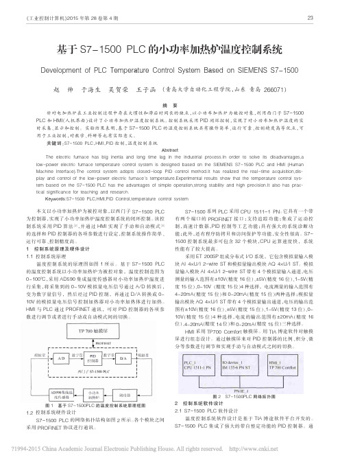
1控制系统原理及硬件设计1.1控制系统原理温度控制系统的原理图如图1所示。
基于S7-1500PLC 的温度控制系统以小功率加热炉为被控对象,温度控制范围为0~100℃,采用AD590集成温度传感器对小功率加热炉温度进行采集,将采集到的0~10V模拟量电压信号通过A/D转换后,变为数字量信号,然后经过PID控制,再通过D/A转换成0~10V的模拟量电压信号控制加热器对小功率加热体进行加热。
HMI与PLC通过PROFINET通讯,可对PID控制器的各项参数进行调节或者进行手动或自动模式间的切换。
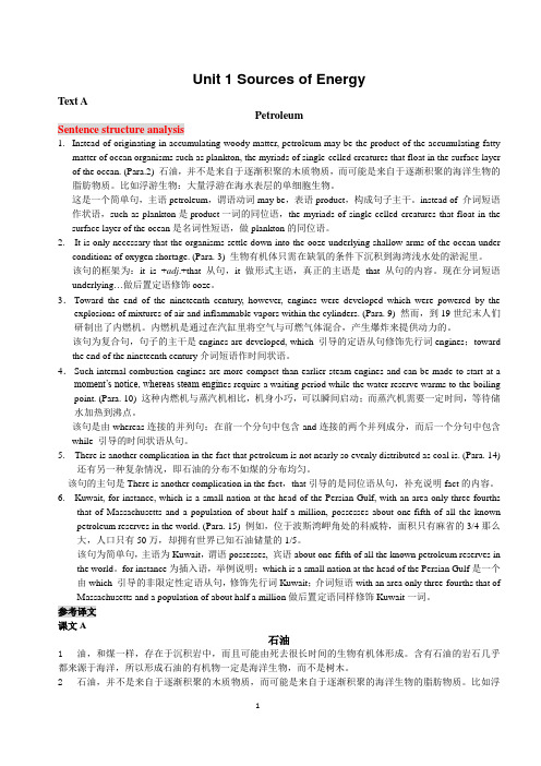
图1基于S7-1500PLC的温度控制系统原理框图1.2控制系统硬件设计S7-1500PLC的网络拓扑结构如图2所示。
各个模块之间采用PROFINET协议进行通讯。
S7-1500系列PLC采用CPU1511-1PN。
它具有一个带有两个端口的PROFINET接口;支持追踪功能;集成了运动控制,高速计数器,PID控制等工艺功能;具有强大的系统诊断功能;此外,还有程序防拷贝和访问保护等功能,安全性很高。
S7-1500控制系统最多可包含32个模块,CPU运算速度快,系统性能有了较大提高。
采用ET200SP组成分布式I/O系统,它包含模拟量输入模块AI4×U/I2-wire ST和模拟量输出模块AQ4×U/I ST。
模拟量输入模块AI4×U/I2-wire ST带有4个模拟量输入通道,电压测量的输入范围有±10V(精度16位)、±5V(精度16位)、1~5V(精度15位)、0~10V(精度15位)4种选择,电流测量的输入范围有4~20mA(精度15位)和0~20mA(精度15位)两种选择;模拟量输出模块AQ4×U/I ST带有4个模拟量输出通道,电压的输出范围有±10V(精度16位)、±5V(精度15位)、1~5V(精度13位)、0~10V(精度15位)4种选择,电流的输出范围有±20mA(精度16位)、4~20mA(精度14位)和0~20mA(精度15位)三种选择。


关于PLC英文文献(1)A PLC programming environment based on a virtual plantSang C. Park & Chang Mok Park & Gi-Nam WangAbstract This paper proposes the architecture of a PLC programming environment that enables a visual verification of PLC programs that integrates a PLC program with a corresponding plant model, so that users can intuitively verify the PLC program in a 3D graphic environment. The plant model includes all manufacturing devices of a production system as well as corresponding device programs to perform their tasks in the production system, and a PLC program contains the control logic for the plant model. For the implementation of the proposed PLC programming environment, it is essential to develop an efficient methodology to construct a virtual device model as well as a virtual plant model. The proposed PLC programming environment provides an efficient construction method for a plant model based on the DEVS (Discrete Event Systems Specifications) formalism, which supports the specification of discrete event models in a hierarchical, modular manner.Keywords PLC verification . Plant model . Virtual device model . Virtual factory simulation1 IntroductionGenerally, industrial production lines are dynamic systems whose states change according to the occurrence of variousevents, and thus exhibit the characteristics of a discrete event system. If manufacturers are to remain competitive in a continuously changing marketplace, they must not only continue to improve their products but also strive to improve production systems continuously [10]. Thus, an efficient prototyping environment for production systems is crucial. A modern production line is a highly integrated system composed of automated workstations such as robots with tool-changing capabilities, a hardware handling system and storage system, and a computer control system that controls the operations of the entire system. The implementation of a production line requires much investment, and decisions at the design stage have to be made very carefully in order to ensure that a highly automated manufacturing system willsuccessfully achieve the intended benefits. Simulation is an essential tool in the design and analysis of complex systems that cannot be easily described by analytical or mathematical models [5, 6]. It is useful for calculating utilization statistics, finding bottlenecks, pointing out scheduling errors and even for creating manufacturing schedules. Traditionally, various simulation languages, including ARENA® and Auto- Mod®, are used for the simulation of manufacturing systems [14]. Those simulation languages have been widely accepted both in industry and in academia; however, they remain as analysis tools for the rough design stage of a production line, because their simulation models are not realistic enough to be utilized for a detailed design or for implementation purposes. For example, real production lines are usually controlled by PLC (ProgrammableLogic Controller) programs [3], as shown in Fig. 1, but conventional simulation languages roughly describe the control logic with independent entity flows (job flows) between processes.Fig. 1 Production system controlled by a PLC programFor a detailed design (virtual prototyping) of a production line, it is necessary to create a much more detailed simulation model that can forecast not only the production capability of the system but also the physical validity and efficiency of co-working machines and control programs. As shown in Fig. 1, various machines that operate simultaneously in an industrial manufacturing system are usually controlled by PLCs, currently the most suitable and widely employed industrial control technology [1–4]. A PLC (Programmable Logic Controller) emulates the behavior of an electric ladder diagram. As they are sequential machines, to emulate the workings of parallel circuits that respond instantaneously, PLCs use an input/ output image table and a scanning cycle. When a program is being run in a PLC, it is continuously executing a scanning cycle. The program scan solves the Boolean logic related to the information in theinput table with that in output and internal relay tables. In addition, the information in the output and internal relay tables is updated during the program scan. In a PLC, this Boolean logic is typically represented using a graphical language known as a ladder diagram [3]. Previous approaches on PLC programs can be categorized into two groups; (1) Verification of a given PLC program [18, 19], and (2) Generation of a dependable PLC program [15–17]. In the first group, various software tools have been developed for the verification of PLCbased systems via the use of timed automata, such asUPPAAL2k, KRONOS, Supremica and HyTech, mainly for programs written in a statement list language also termed Boolean [2]. These software tools verify PLC programs to a certain extent; however, they remain limited. Since they are mainly focusing on the checking of theoretical attributes (safety, liveness, and reachability), it is not easy for users to determine whether the PLC programs actually achieve the intended control objectives. In the second group, many researchers have focused on the automatic generation of PLC programs from various formalisms including state diagrams, Petri nets and IDEF0. These formalisms can help the design process of control logics, however, it is still difficult to find hidden errors, which are the most difficult part of the verification of a control program. To cope with the problem, we need a more transparent PLC programming environment helping users to recognize hidden errors. The objective of this paper is to propose the architecture of a PLC programming environment that enables the visual validation of a PLC program. The proposed PLC programming environment employs a virtual plant model consisting of virtual devices, so that users can easily verify the PLC program. The overall structure of the paper is as follows. Section 2 illustrates the architecture of the proposed PLC programming environment, while Section 3 describes an efficient construction methodology for a plant model, which can be synchronized with a PLC program. Section 4 shows an example and illustrations. Finally, concluding remarks are given in Section 5.2 Visual validation of PLC programsTo design the architecture of the PLC programming environment, it is importantto understand the basic procedure used to construct a PLC program (ladder diagram). Chuang et al. [1] proposed a procedure for the development of an industrial automated production system that consists of nine steps. They are: (1) Define the process to be controlled; (2) Make a sketch of the process operation;(3) Create a written sequence listing of the process step by step; (4) On the sketch, add the sensors needed to carry out the control sequence; (5) Add the manual controls needed for the process-setup or for operational checks; (6) Consider the safety of the operating personnel and make additions and adjustments as needed;(7) Add the master stop switches required for a safe shutdown; (8) Create a ladder logic diagram that will be used as a basis for the PLC program; and (9) Consider the possible points where the process-sequence may go astray. The most time-consuming task for the control logic designers is the 8-th step, which is usually done by the repetitive method of ‘Code writing, testing and debugging’until the control objectives are achieved [2]. The bottleneck of the 8-th step is that the conventional PLC programming environments are not especially intuitive, particularly for the testing and debugging of a PLC program, as they showonly the status of a PLC without providing any links to the target system (production line). For the validation of a PLC program, engineers need to imagine the state changes of a production line from the input and output ports of a PLC. That is the reason conventional PLC programming environments are often inefficient and prone to human error. As the configurations of production lines and their control programs become more complicated, there is a strong need for a more intuitive PLC programming environment. It is hoped that this paper will take positive steps in this direction. Figure 2 shows the architecture of the proposed PLC programming environment. It consists of two layers, a model layer and an application layer. The model layer has three models, a plant model (virtual factory model), a PLC program (control model) and an I/O mapping model. The plant model includes all manufacturing devices of the production system as well as the corresponding device programs to perform their tasks inthe production system, and the PLC program contains the control logic for the plant model. For the integration of the plant model and the PLC program, it is necessary to define the mapping between the plant model and the PLC program, which is described by the I/O mapping model. The application layer simultaneously provides two interfaces to users. The ‘PLCsimulator’ performs the simulation of the control program, and the ‘plant model visualizer’ shows the corresponding plant model (3D graphic models) reflecting the changing states of the production system during the PLC simulation. Thus, it becomes much easier for users to verify the PLC program through the plant model visualizer.。

2022年考研考博-考博英语-东华大学考试预测题精选专练VII(附带答案)第1套一.综合题(共25题)1.单选题Hot metal ______ as it grows cooler.问题1选项A.contractsB.reducesC.condensespresses【答案】A【解析】考查动词辨析。
A项contract“收缩、订约”;B项reduce“减少”;C项condense“浓缩、凝结”;D项compress“压缩、压紧、精简”;句意:热金属一变冷就收缩。
因此该题A项正确。
2.单选题This is but a________ of the total amount of information which the teenager has stored. 问题1选项A.frictionB.fractionC.factionD.fracture【答案】B【解析】考查名词辨析。
A选项“friction”,意为“摩擦力,摩擦”,B选项“fraction”,意为“分数,部分”;C选项“faction”,意为“派别,小集团”,D选项“fracture”,意为“破裂,断裂”,句意:这只是青少年所储存的全部信息的一小部分。
因此,B选项符合句意。
3.单选题The ________ that she suggested for discussion were based on the most recent medical research. 问题1选项A.contributionsB.occupationsC.expostulationsD.amendments【答案】D【解析】考查名词辨析。
A选项“contribution”,意为“贡献,捐款”;B选项“occupation”,意为“占有权,职业”;C选项“expostulation”意为“劝导,忠告”;D选项“amendment”,意为“改善,修正建议”。

INDUSTRIAL AND COLLABORATIVE CONTROL SYSTEMS- A COMPLEMENTARY SYMBIOSIS –-Looking at today’s control system one can find a wide variety of implementations. From pure industrial to collaborative control system (CCS) tool kits to home grown systems and any variation in-between.Decisions on the type of implementation should be driven by technical arguments Reality shows that financial and sociological reasons form the complete picture. Any decision has it’s advantages and it’s drawbacks. Reliability, good documentation and support are arguments for industrial controls. Financial arguments drive decisions towards collaborative tools. Keeping the hands on the source code and being able to solve problems on your own and faster than industry are the argument for home grown solutions or open source solutions. The experience of many years of operations shows that which solution is the primary one does not matter, there are always areas where at least part of the other implementations exist. As a result heterogeneous systems have to be maintained. The support for different protocols is essential. This paper describes our experience with industrial control systems, PLC controlled turn key systems, the CCS tool kit EPICS and the operability between all of them.-INTRODUCTIONProcess controls in general started at DESY in the early 80th with the installation of the cryogenic control system for the accelerator HERA (Hadron-Elektron-Ring-Anlage). A new technology was necessary because the existing hardware was not capable to handle standard process controls signals like 4 to 20mA input and output signals and the software was not designed to run PID control loops at a stable repetition rate of 0.1 seconds. In addition sequence programs were necessary to implement startup and shutdown procedures for the complex cryogenic processes like cold boxes and compete compressor streets.Soon it was necessary to add interfaces to field buses and to add computing power to cryogenic controls. Since the installed D/3 system[1] only provided an documented serial connection on a multibus board, the decision was made to implement a DMA connection to VME and to emulate the multibus board’s functionality. The necessary computing power for temperature conversions came from a Motorola MVME 167 CPU and the field bus adapter to the in house SEDAC field bus was running on an additional MVME 162. The operating system was VxWorks and the application was the EPICS toolkit.Since this implementation was successful it was also implemented for the utility controls which were looking for a generic solution to supervise their distributed PLC’s.A SELECTION OF PROCESS CONTROL SYSTEMS AT DESYDCS (D/3)As a result of a market survey the D/3 system from GSE was selected for the HERA cryogenic plant. The decision was fortunate because of the DCS character of the D/3. The possibility to expand the system on the display- and on the I/O side helped to solve the increasing control demands for HERA. The limiting factor for the size of the system is not the total number of I/O but the traffic on the communication network. This traffic is determined by the total amount of archived data not by the data configured in the alarm system. The technical background of this limitation is the fact that archived data are polled from the display servers whereas the alarms are pushed to configured destinations like alarm-files, (printer) queues or displays.SCADA Systems with DCS Features (Cube)The fact that the D/3 system mentioned above had some hard coded limitations with respect to the Y2K problem was forcing us to look for an upgrade or a replacement of the existing system. As a result of a call for tender the company Orsi with their product Cube came into play [2]. The project included a complete replacement of the installed functionality. This included the D/3 as well as the integration of the DESY field bus SEDAC and the temperature conversion in VME. The project started promising. But soon technical and organizational problems were pushing the schedule to it’s lim its which were determined by the HERA shutdown scheduled at that time.The final acceptance test at the vendors site showed dramatic performance problems. Two factors could be identified as the cause of these problems. The first one was related to the under estimated CPU load of the 6th grade polynomial temperature conversion running at1 Hz. The second one was the additional CPU load caused by the complexfunctionality of the existing D/3 system. Here it was underestimated that each digital and analog inpu t and output channel had it’s own alarm limits in the D/3 system. In a SCADA like system as Cube the base functionality of a channel is to read the value and make it available to the system. Any additional functionality must be added.Last not least the load on the network for polling all the alarm limits – typically for a SCADA system – was also driving the network toit’s limits.Finally the contract with Orsi was cancelled and an upgrade of the D/3 system was the only possible solution. It was finally carried out in march 2003.In any case it should be mentioned that the Cube approach had the advantage of a homogeneous configuration environment (for the Cube front end controllers) – compared with heterogeneous environments for ‘pure’ SCADA systems.SCADA (PVSS-II)The H1 experiment at the HERA accelerator decided to use PVSS-II for an upgrade of their slow control systems[3]. The existing systems were developed by several members of the H1 collaboration and were difficult to maintain. The decision to use PVSS as a replacement was driven by the results of an extensive survey carried out at CERN by the Joint Controls Project [4]. PVSS is a ‘pure’ Supervisory And Data Acquisition System (SCADA). It provides a set of drivers for several field buses and generic socket libraries to implement communication over TCP/IP. The core element is the so called event manager. It collects the data (mostly by polling) from the I/O devices and provides an event service to the attached management services like: control manager, database manager, user interface, API manager and the built in HTTP server. The PVSS scripting library allows to implement complex sequences as well as complex graphics. Compared with other SCADA systems PVSS comes with one basic feature: it providesa t rue object oriented API to the device’s data.One major disadvantage of SCADA systems is the fact that two databases, the one for the PLC and the one for the SCADA system must be maintained. Integrated environments try to overcome this restriction.EPICSEPICS has emerged at DESY from a problem solver to a fully integrated control system. Starting from the data collector and number cruncher for the cryogenic control system, EPICS made it’s way to become the core application for the DESY utility group. In addition it is used wherever data is available through VME boards or by means of Industry Pack (IP) modules. For those cryogenic systems which are not controlled by the D/3 system EPICS is used with it’s complete functionality. In total about 50 Input Output Controller (IOC) are operational processing about 25 thousand records.1 EPICS as a SCADA SystemThe utility group ( water, electrical power, compressed air, heatingand air conditioning) is using a variety of PLC’s spread out over the whole DESY sit e. EPICS is used to collect the data from these PLC’s over Profibus (FMS and DP) and over Ethernet (Siemens H1 and TCP).The IOC’s provide the interfaces to the buses and collect the data.The built in alarm checking of the EPICS records is used to store and forward alarm states to the alarm handler (alh) of the EPICS toolkit.In addition tools like the channel archiver and the graphic display (dm2k) are used. The default name resolution (by UDP broadcast) and the directory server (name server) are used to connectclient and server applications over TCP. All of these are basically SCADA functions.The textual representation of all configuration files ( for the IOC, the graphic tool, the alarm handler and the archiver) provides a flexible configuration scheme. At DESY the utility group has developeda set of tools to create IOC databases and alarm configuration filesfrom Oracle. This way the controls group provides the service to maintain the EPICS tools and the IOC’s while the users can concentrate on the equipment being controlled.2 EPICS as a DCS SystemBesides the basic components of a SCADA system EPICS also providesa full flavoured Input Output Controller (IOC). The IOC provides allof the function a DCS system requires, such as: a standard set of properties implemented in each record, built in alarm checking processed during the execution of each record; control records like PID etc.; configuration tools for the processing engine. The flexible naming scheme and the default display and alarm properties for each record ease the connection between the operator tools and the IOC’s.The flexible data acquisition supports the poll mode as well as the publish subscribe mode. The latter reduces the traffic drastically.PLC’sPLC’s provide nowadays the same rich functionality as it was known from stand alone control systems in the past. Besides the basic features like the periodic execution of a defined set of functions they also allow extensive communication over Ethernet including embedded http servers and different sets of communication programs.Besides the communication processors, display processors can be linked to PLC’s to provide local displays which can be comprised as touch panels for operator intervention and value settings.These kind of PLC’s a re attractive for turn key systems which are commissioned at the vendors site and later integrated into the customers control system.Intelligent I/ONew developments in I/O devices allow to ‘cluster’ I/O in even smaller groups and connect theses clustered I/O channels directly to the control system. PLC’s are not any more necessary for distributed I/O. Simple communication processors for any kind of field buses or for Ethernet allow an easy integration into the existing controls infrastructure. Little local engines can run IEC 61131 programs. The differences between PLC’s and intelligent I/O subsystems fade away.FUNCTIONALITYThe ever lasting question why control systems for accelerators and other highly specialized equipment are often home grown or at least developed in a collaboration but only in rare cases commercial shall not be answered here. We try to summarize here basic functionalities of different controls approaches.Front-end ControllerOne of the core elements of a control system is the front-end controller. PLC’s can be used to implement most of the functions to control the equipment. The disadvantage is the complicated access to the controls properties. For instance all of the properties of a control loop like the P, I and D parameter, but also the alarm limits and other additional properties must be addressed individually in order to identify them in the communication protocol and last not least in the display-, alarm- and archive programs. In addition any kind of modifications of these embedded properties is difficult to track because two or more systems are involved. This might be one strong argument why control loops are mainly implemented on the IOC level rather than PLC’s.1 I/O and Control LoopsComplex control algorithms and control loops are the domain of DCS alike control systems. The support for sets of predefined display and controls properties is essential. If not already available (like in DCS systems) such sets of generic properties are typically specified throughout a complete control system (see namespaces).2 Sequence/ State programsSequence programs can run on any processor in a control system. The runtime environment depends on the relevance of the code for the control system. Programs fulfilling watchdog functions have to run on the front-end processor directly. Sequence programs for complicated startup and shutdown procedures could be run on a workstation as well. The basic functionality of a state machine can be even implemented in IEC 61131. Code generators can prod uce ‘C’code which can be compiled for the runtime environment.3 Supported HardwareThe support for field buses and Ethernet based I/O is a basic functionality for SCADA type systems it is commercially available from any SCADA system on the market. The integration of specific hardware with specific drivers and data conversion is the hard part in a commercial environment. Open API’s or scripting support sometimes help to integrate custom hardware. If these tools are not provided for the control system it is difficult – if not impossible - to integrate custom hardware.New industrial standards like OPC allow the communication with OPC aware devices and the communication between control systems. One boundary condition for this kind of functionality is the underlying operating system. In the case of OPC it is bound to DCOM which is a Microsoft standard. UNIX based control systems have a hard time to get connected. Only control systems supporting multiple platforms can play a major role in a heterogeneous environments.As a result the limited support for custom- or specialized hardware may give reason for the development of a new control system.Display and OperationBesides the front-end system the operator interfaces play a major role for the acceptance of a control system. SCADA tools come with a homogeneous look and feel throughout their set of tools. Toolkits implemented in a collaboration might vary because the individual tools were developed by different teams.1 GraphicSynoptic displays are the advertising sign for any control system.Commercial synoptic displays come with a rich functionality and lots of special features. Starting to make use of all these features one will find out that all individual properties of the graphic objects must be specified individually. Since SCADA systems must be generic they cannot foresee that an input channel does not only consist ofa value but also consists of properties like display ranges and alarmvalues. Defining all of these properties again and again can be a pretty boring job. Some systems allow to generate prototypes of graphic objects. These prototype or template graphics are complex and need a specialist to generate them.DCS or custom synoptic display programs can make use of the common set of properties each I/O point provides. This predefined naming scheme will fill in all standard property values and thus only require to enter the record – or device name into the configuration tool.A clear advantage for control systems with a notion of I/O objectsrather than I/O points.2 AlarmingAlarms are good candidates to distinguish between different control system architectures. Those systems which have I/O object implemented also provide alarm checking on the front-end computer. Those systems which only know about I/O points have to add alarm checking into the I/O processing. While the I/O object approach allows to implement alarm checking in the native programming language of the front-end system, I/O point oriented systems typically have to implement this functionality in their native scripting language. This is typically less efficient and error prone because all properties must be individually configured. This leads to a flood of properties. Not only the error states for each I/O point wind up to be individual I/O points but also the alarm limits and the alarm severity of each limit must be defined as I/O points if it is desired to be able to change their values during runtime.Besides this impact on the configuration side the processing and forwarding of alarms makes the difference between SCADA and DCS systems. Since SCADA systems inherently do not ‘know’ about alarms, each alarm state must be polled either directly from the client application or in advanced cases from an event manager which will forward alarm states to the clients. In any case a lot of overhead for ‘just’ checking alarm limits. DCS system again have the advantage that clients can either register themselves for alarm states und thus get the information forwarded or are configured to send alarmchanges to certain destinations spread around the control system.The latter case is only possible for systems which in total are configured with all the nodes taking part in the controls network.3 Trending and ArchivingTrending has become an important business in control systems architectures. Trends are necessary to trace error conditions or for post mortem and performance analysis of the controlled plant. Besides some custom implementations which are capable to store the data of complete control objects, most of the trending tools archive scalar data. Additional features like conditional trending or correlation plots make up the difference between individual implementations.4 Programming InterfacesWith respect to open programming interfaces PLC’s and DCS systems have a common strategy. They are running reliably because there’s no way to integrate custom code which could interfere with the internalprocessing. As a consequence the customer has to order ‘specials’ - which are extremely expensive –or forget about it and use the system as a black box.Since SCADA systems by definition must be able to communicate witha variety of I/O subsystems they already have some built in API’swhich allow to integrate custom functionality.Specially collaborative systems need a certain openness to fulfill all the requirements from various development groups. Programming interfaces on all levels like font-end I/O, front-end processing, networking etc. are mandatory. A clear advantage for this type of system.5 RedundancyIf redundancy means the seamless switch which takes over all the states and all the values of the I/O and all states of all programs currently running, it is a domain of only a few DCS systems. Custom or CCS implementation do not provide this kind of functionality. Maybe because of the immense effort and the fact that it is only required in rare cases.Besides processor redundancy, redundant networks or I/O subsystems are available for certain commercial DCS systems. Again – a domain which is not covered by SCADA or CCS implementations.Advanced safety requirements may be covered by redundant PLC subsystems. These are for instance installed in (nuclear) power plants.Requirements for Personal Protection Systems (PPS) can sometimes only be fulf illed by redundant PLC’s. In process controls redundant PLC’s are only used in rare cases.6 NamespaceThe flat namespace of SCADA systems has already been described in the alarm section. Some SCADA systems (like PVSS-II) provide the notion of control objects or structured data which is a rare case. In all other cases so called field objects must be specified. These are objects which consist of a list of properties (implemented as I/O points) and a set of methods ( implemented asmacros or function calls).One of these approaches is the UniNified Industrial COntrol System (UNICOS) at CERN [5].DCS systems and most of the custom/ collaborative systems are record –or device oriented. The difference being that typically one record is connected to a single I/O point and provides this way all sub features of a record implementation like individual engineering units, display- and alarm limits. The device oriented approach allows toconnect several I/O points. The major difference being the fact that an object oriented device implementation provides methods and states for a device while (EPICS) records only serve a certain set of built in functions.Naming hierarchies are not specific to a type of implementation. They are available for some systems of any kind. For sure hierarchical naming schemes are desirable.IMPLEMENTATION STRATEGIESAfter having shown all the possible controls approaches it is time to have a look at the implementation of control systems.Starting from the I/O level one has to decide whether commercial solution are required, feasible or wanted. Special I/O does not always require custom solution for the font-end controller. Signals can be converted into standard signals but this does not apply for all kinds of signals. Resolution, repetition rates and signal levels might require custom developments which must be integrated into the overall control architecture. Even if the signals can not be connected to standard I/O interfaces it might be possible to develop I/O controllers which implement a field bus interface which allow the integration with commercial control systems. Once this level of integration is not possible custom front-end controllers like VME crates come into play.Besides the decision whether special I/O requires dedicated custom solutions one has to decide who will do which part of the work? Does for instance the necessity of VME crates prohibit the delivery of a ‘turn key’ system built by industry? Or does a PLC based front-end system require a commercial SCADA system for high level controls?Turn Key SystemsIt is a clear trend in industry to deliver turn key systems. It allowsa modular design of the whole system. Individual components can besubcontracted to several companies and tested locally. Once delivered to the construction site the primary acceptance tests have already been passed and the second phase, to integrate the subsystem into the global control system begins.While the detailed specification of control loops etc. is now part of the subsystems contract, the customer has to specify clearly how much information of the subsystem must be made available, what the data structures will look like and which connection (field bus/ Ethernet) will be used.Most turn key systems are delivered with PLC’s. The constructionof the Swiss Light Source (SLS) has shown that also a VME based I/O system running a CCS – in this case EPICS – can be successfully commissioned [6].PLC Based SystemsPLC based systems are a consequence of the turn key ansatz. The next obvious approach m ight be to look besides commercial PLC’s also for commercial SCADA systems. The advantage is clearly the same like for the PLC: stable software, no programming –only configuration, support and good documentation. At DESY we have successfully established a relation between the controls group which provides a CCS service based on EPICS and the utility group which uses the EPICS configuration tools to set up their control environment. The big advantage though being that the EPICS code can be adjusted to the special requirements from both sides.Industrial SolutionsThe difference between CCS solutions and commercial solutions is fading away as soon as industry starts to deliver and support collaborative control systems. At KEK a company was contracted to supply programmers for the KEK-B upgrade. These programmers were trained in writing drivers and application code for EPICS. As a result the KEK-B control system is a mixture of software developed partly by industry and partly in house. This is another example for an industrial involvement for a CCS implementation.COSTThe question: “Was is the total cost of ownership (TCO) of a PC?”has kept people busy since PC’s exist. The answers vary to all extremes. The question what is the TCO of a control system might give similar results.If you go commercial you have to pay for the initial licenses the implementation which is typically carried out by the supplier or bya subcontractor, and you pay for the on going software support whichmight or might not include the update license fee.If you go for a collaborative approach, you might contract a company or implement everything on your own. A question of ‘time and money’ as industry says. You will have more freedom and flexibility for your implementations but also a steeper learning curve. You can rely on the collaboration to provide new features and versions or you can contribute yourself. A major difference calculating the long term costs for a control system.At DESY one can roughly estimate that the (controlsapplication)-support for a commercial approach – here D/3 - and the -support for a collaborative approach – here EPICS - is nearly the same. The software support and upgrade license fee is equivalent to one and a half FTE’s – which is about the manpower necessary to support new hardware and to upgrade EPICS.CONCLUSIONSDepending on the size and the requirements for a controls project the combination of commercial solutions and solutions based on a collaborative approach is possible in any rate between 0 and 100 percent. This applies for all levels from implementation to long term support. Special requirements on safety issues or a lack of manpower might turn the scale commercial. The necessity to interface special hardware, special timing requirements, the ‘having the code in my hands’ argument or the initial costs for commercial solutions will turn the scale collaborative. As long as collaborative approaches like EPICS stay up to date and run as stable and robust as commercial solutions, both will keep their position in the controls world in a complementary symbiosis.外文资料翻译外文翻译译文工业控制系统和协同控制系统当今的控制系统被广泛运用于许多领域。
Unit 1 Sources of EnergyText APetroleumSentence structure analysis1. Instead of originating in accumulating woody matter, petroleum may be the product of the accumulating fattymatter of ocean organisms such as plankton, the myriads of single-celled creatures that float in the surface layer of the ocean. (Para.2) 石油,并不是来自于逐渐积聚的木质物质,而可能是来自于逐渐积聚的海洋生物的脂肪物质。
比如浮游生物:大量浮游在海水表层的单细胞生物。
这是一个简单句,主语petroleum,谓语动词may be,表语product,构成句子主干。
instead of 介词短语作状语,such as plankton是product一词的同位语,the myriads of single-celled creatures that float in the surface layer of the ocean是名词性短语,做plankton的同位语。
2. It is only necessary that the organisms settle down into the ooze underlying shallow arms of the ocean underconditions of oxygen shortage. (Para. 3) 生物有机体只需在缺氧的条件下沉积到海湾浅水处的淤泥里。
该句的框架为:it is +adj.+that从句,it做形式主语,真正的主语是that从句的内容。
现在分词短语underlying…做后置定语修饰ooze。

高中英语科技论文阅读单选题40题1. The term "nanotechnology" refers to the manipulation of matter on an extremely small _____.A. scaleB. levelC. degreeD. range答案:A。
本题考查名词词义辨析。
“scale”有“规模、范围、程度”的意思,“on a small scale”表示“小规模地”,在“nanotechnology”(纳米技术)中,“scale”强调物质操作的规模大小;“level”侧重于水平、级别;“degree”指程度、度数;“range”表示范围、幅度。
此处“nanotechnology”涉及的是物质操作的极小规模,所以选A。
2. In the field of artificial intelligence, the concept of "machine learning" involves the ability of computers to ______ patterns in data.A. detectB. discoverC. exposeD. reveal答案:A。
“detect”有“察觉、探测、发现”的意思,强调通过观察或检测来发现;“discover”侧重于首次发现原本存在但未被知晓的事物;“expose”指暴露、揭露;“reveal”意为揭示、展现。
在“machine learning”((机器学习)中,计算机是通过分析数据来“察觉”模式,A 选项更符合语境。
3. The "quantum physics" phenomenon is characterized by the behavior of particles at the ______ level.A. atomicB. molecularC. subatomicD. microscopic答案:C。

百度文库让每个人平等地捉升口我可编程逻辑控制器PLC外文文献翻译(含:英文原文及中文译文)文献出处:Kinna D. Programmable Logic Controllers (PLC) [J]. Fusion Engineering & Design, 2015, 2(12):72-83. 英文原文Programmable Logic Controllers (PLC)Kinna Dari1MotivationProgrammable Logic Controllers (PLC), a computing device invented by Richard E. Morley in 196& have been widely used in industry including manufacturing systems, transportation systems, chemical process facilities, and many others. At that time, the PLC replaced the hardwired logic with soft-wired logic or so-called relay ladder logic (RLL), a programming language visually resembling the hardwired logic, and reduced thereby the configuration time from 6 months down to 6 days [Moody and Morley, 1999].Although PC based control has started to come into place, PLC based control will remain the technique to which the majority of industrial applications will adhere due to its higher performance, lower price, and superior reliability in harsh environments Moreover, according to a studyon the PLC market of Frost and Sullivan [1995], an increase of the annual sales volume to 15 million PLCs per year with the hardware value of more 百度文库让每个人平等地捉升口我than 8 billion US dollars has been predicted, though the prices ofcomputing hardware is steadily dropping. The inventor of the PLC, Richard E Morley, fairly considers the PLC market as a 5-billion industry at the present time.In general, the productivity in generating PLC is far behind compared to other domains, for instance, VLSI design, where efficient computer aided design tools are in practice - Existent software engineering methodologies are not necessarily applicable to the PLC based software design because PLC-programming requires a simultaneous consideration of hardware and software - The software design becomes, thereby, more and more the major cost driver. In many industrial design projects, more than 50% of the manpower allocated for the control system design and installation is scheduled for testing and debugging PLC programs [Rockwell, 1999].PLCs (programmable logic controllers) are the control hubs for a wide variety of automated systems and processes. They contain multiple inputs and outputs that use transistors and other circuitry to simulate switches and relays to control equipment. They are programmable via software interfaced via standard computer interfaces and proprietary languages and network options -Programmable logic controllers I/O channel specifications include total number of points, number of inputs and outputs, ability to expand, and maximum number of channels - Number of points is the sum of the inputs百度文库让每个人平等地捉升口我and the outputs - PLCs may be specified by any possible combination of these values. Expandable units may be stacked or linked together to increase total control capacity. Maximum number of channels refers to the maximum total number of input and output channels in an expanded systemPLC system specifications to consider include scan time, number of instructions, data memory, and program memory. Scan time is the time required by the PLC to check the states of its inputs and outputs. Instructions are standard operations (such as math functions) available to PLC software. Data memory is the capacity for data storage - Program memory is the capacity for control software.Programmable logic controllers use a variety of software programming languages for control. These include IEC 61131-3, sequential function chart (SFC), function block diagram (FBD), ladder diagram (LD), structured text (ST), insti-uction list (IL), relay ladder logic (RLL), flow chart, C, and Basic. The IEC 61131-3 programming environment provides support for five languages specified by the global standard: Sequential Function Chart, Function Block Diagram, Ladder Diagram, Structured Text, and Instruction List. This allows for multi-vendor compatibility and multi-language programming. SFC is a graphical language that provides coordination of program sequences, supporting alternative sequence selections and parallelsequences. FBD uses a broad function library to build complex procedures百度文库让每个人平等地捉升口我in a graphical format - Standard math and logic functions may be coordinated with customizable communication and interface functions. LD is a graphic language for discrete control and interlocking logic. It is completely compatible with FBD for discrete function control. ST is a text language used for complex mathematical procedures and calculations less well suited to graphical languages. IL is a low-level language similar to assembly code - It is used in relatively simple logic instructions. RelayLadder Logic (RLL), or ladder diagrams, is the primary programming language for programmable logic controllers (PLCs) - Ladder logic programming is a graphical representation of the program designed to look like relay logic. Flow Chart is a graphical language that describes sequential operations in a controller sequence or application. It is used to build modular, reusable function libraries.C is a high level programming language suited to handle the most complex computation, sequential, and data logging tasks. It is typically developed and debugged on a PC. BASIC is a high level language used to handle mathematical, sequential, data capturing and interface functions・2ResumeA PLC (programmable Logic Controller) is a device that was invented toreplace the necessary sequential relay circuits for control. The PLC works by looking at its input and depending upon their state, turning on/off its百度文库让每个人平等地捉升口我outputs - The user enters a program, usually via software or programmer, which gives the desired results.PLC is used in many u real world H applications. If there is industry present, chance are good that there is a PLC present. If you are involved in machining, packing, material handling, automated assembly or countless other industries, you are probably already using them. If you are not, you are wasting money and time- Almost any application that needs some typeof electrical control has a need for a PLC -For example, let's assume that when a switch turns on we want to turn a solenoid on for 5 second and then turn it off regardless of how long the switch is on for. We can do this with a simple external timer. But what if the process included 10 switches and solenoids? We should need 10 external times What if the process also needed to count how many times the switch individually turned on? We need a lot of external counters.As you can see the bigger the process the more of a need we have for a PLC - We can simply program the PLC to count its input and turn the solenoids on for the specified time. We will take a look at what is considered to be the H top20" PLC instructions. It can be safely estimated that with a firm understanding of these instructions one can solve more than 80% of the applications in existence・百度文库让每个人平等地捉升口我Of course we will learn more than just this instruction to help you solve almost ALL potential PLC applications.The PLC mainly consists of a CPU, memory areas, and appropriatecircuits to receive input/output data. We can actually consider the PLC to be a box full of hundreds or thousands of separate relay, counters, times and data storage locations, Do these counters, timers, etc. really exist? No, theydon't “physically" exist buE y r simi d atedi and be considered software counters, timers, etc.・These internal relays are simulated through bit locations in registers.What does each part do? Let me tell you.Input RelaysThese are connected to the outside world. They physically exist and receivesignals from switches, sensors. Typically they are not relays but rather they are transistors・Internal Utility RelaysThese do not receive signals from the outside world nor do they physicallyexist, they are simulated relays and are what enables a PLC to eliminate external relays - There are also some special relays that are dedicated to performing only one task. Some are always on while some are always off. Some are on only once during power-on and are typically used for initializing data that was stored.Counters百度文库让每个人平等地捉升口我These again do not physically exist. They are simulated counters and they can be programmed to count pulses. Typically these counters can count up, down or both up and down. Since they are simulated, they are limited in their counting speed - Some manufacturers also include high-speed counters that are hardware based. We think of these as physically existing. Most times these counters can count up, down or up and down.TimersThese also do not physically exist. They come in many varieties and increments. The most common type is an on-delay type. Others include off- delays and both retentive and non-retentive types - Increments vary from1ms through Is.Output RelaysThere are connected to the outside world. They physically exist and send on/off signals to solenoids, lights,etc. They can be transistors, relays, or triacs depending upon the model chosen. Data StorageTypically there are registers assigned to simply store data. They are usually used as temporary storage for math or data manipulation. They can also typically be used to store data when power is removed form the PLC-Upon power-up they will still have the same contents as before power was moved. Very convenient and necessary!A PLC works by continually scanning a program - We can think ofthis scan cycle as consisting of 3 important steps. There are typically more than 3 but we can focus on the important parts and not worry about the others, Typically the others are checking the system and updating the current百度文库让每个人平等地捉升口我internal counter and timer values -Step 1 is to check input status, First the PLC takes a look at each input to determine if it is on off. In other words, is the sensor connected to the first input on? How about the third...It records this data into its memory to be used during the next step.Step 2 is to execute program. Next the PLC executes your program one instruction at a time. Maybe your program said that if the first input was on then it should turn on the first output. Since it already knows which inputs are on/off from the previous step, it will be able to decide whether the first output should be turned on based on the state of the first input. It will store the execution results for use later during the next step.Step 3 is to update output status. Finally the PLC updates the status the outputs. It updates the outputs based on which inputs were on during the first step and the results executing your program during the second step. Based on the example in step 2 it would now turn on the first output because the first input was on and your program said to turn on the first output when this condition is true.After the third step the PLC goes back to step one repeats the stepscontinuously. One scan time is defined as the time it takes to execute the 3 steps continuously. One scan time is defined as the time it takes to execute the 3 steps listed above - Thus a practical system is controlled to perform specified operations as desired.百度文库让每个人平等地捉升口我3PLC StatusThe lack of keyboard and other input-output devices is very noticeable on a PLC. On the front of the PLC there are normally limited status lights. Common lights indicate.These lights are normally used for debugging. Limited buttons will also be provided for PLC hardware. The most common will be a run/program switch that will be switched to program when maintenance is being conducted, and back to run when in production. This switch normally requires a key to keep unauthorized personnel from altering the PLC program or stopping execution. A PLC will almost never have an on-off switch or reset button on the front. This needs to be designed into the remainder of the system.The status of the PLC can be detected by ladder logic also. It is common for programs to check to see if they are being executed for the first time, as shown in Figure 1. Hie first seal input will be tme on the very first time the ladder logic is scanned, but false on every other scan. In this case the address for 'first scan' in a PLC-5 is ,S2:1/14\ With the logic in the example the first scan will seal on light ;until , cleaF is turned on. So thelight will turn on after the PLC has been turned on, but it will turn off and stay off after 'cleaF is tiinied on.百度文库让每个人平等地捉升自我4Memory TypesThere are a few basic types of computer memory that are in use today.RAM (Random Access Memory) - this memory is fast, but it will lose its contents when power is lost, this is known as volatile memory. Every PLC uses this memory for the central CPU when running the PLC -ROM (Read Only Memory) - this memory is permanent and cannot be erased. It is often used for storing the operating system for the PLC -EPROM (Erasable Programmable Read Only Memory) - this is memory that can be programmed to behave like ROM, but it can be erased with ultraviolet light and reprogrammed・EEPROM (Electronically Erasable Programmable Read Only Memory) -This memory can store programs like ROM - It can be programmed and erased using a voltage, so it is becoming more popular than EPROMs.All PLCs use RAM for the CPU and ROM to store the basic operating system for the PLC - When the power is on the contents of the RAM will be kept, but the issue is what happens when power to the memory is lost. Originally PLCvendors used RAM with a battery so that the memory contents would not be lost if the power was lost. This method is still in use, but is losing favor. EPROMs have also been a popular choice for programming PLCs. The EPROM is programmed out of the PLC, and then placed in the PLC. When the PLC is turned on the ladder logic program on10百度文库让每个人平等地捉升口我the EPROM is loaded into the PLC and run. This method can be very reliable, but the erasing and programming technique can be time consuming - EEPROM memories are a permanent part of the PLC, and programs canbe stored in them like EPROM. Memory costs continue to drop, and newer types (such as flash memory) are becoming available, and these changes will continue to impact PLCs.5Objective and Significance of the ThesisThe objective of this thesis is to develop a systematic software design methodology for PLC operated automation systems. The design methodology involves high-level description based on state transition models that treat automation control systems as discrete event systems, a stepwise design process, and set of design rules providing guidance and measurements to achieve a successful design. The tangible outcome of this research is to find a way to reduce the uncertainty in managing the control software development process,that is, reducing programming and debugging time and their variation, increasing flexibility of the automation systems, and enabling software reusability through modularity. The goal is to overcome shortcomings of current programming strategies that are based on the experience of the individual software develope 匚中文译文可编程逻辑控制器(PLC)吉娜达尔11百度文邮-让每个人平零地捉开口我1动机可编程逻辑控制器(PLC)是Richard E. Morley于1968年发明的计算设备,己广泛应用于工业领域,包括制造系统,运输系统,化学处理设施等等。

PLC technique discussion and future developmentAlong with the development of the ages, the technique that is nowadays is also gra the operation that list depends 。
dually perfect, the competition plays more more strongthe artificial has already can't satisfied with the current manufacturing industry foreground, also can't guarantee the request of the higher quantity and high new the image of the technique business enterprise.The people see in produce practice, automate brought the tremendous convenience and the product quantities for people up of assurance, also eased the personnel's laborstrength, reduce the establishment on the personnel. The target control of the hard realization in many complicated production lines, whole and excellent turn, the best decisionetc., well-trained operation work, technical personnel or expert, governor but can judgeand operate easily, can acquire the satisfied result. The research target of the artificial intelligence makes use of the calculator exactly to carry out, imitate these intelligences behavior, moderating the work through person's brain and calculators, with the mode that person's machine combine, for resolve the very complicated problem to look for the best pathWe come in sight of the control that links after the electric appliances in various situation, that is already the that time generation past, now of after use in the mold a perhaps simple equipments of grass-roots control that the electric appliances can do for the loAnd the PLC emergence also became the epoch-making topic, adding the vw level only。

吴君周WU Junzhou吴君周1989.09—/男/浙江温州人/讲师/工作于浙江安防职业技术学院/研究方向为教学改革(温州325016)摘要传统的PLC课程教学过程偏重于理论的掌握,而忽视了实践动手解决问题能力的培养,针对这个问题,本文以浙江安防职业技术学院安全防范技术专业17级和18级学生为研究对象,对PLC技术课程进行项目化教学改革。
以项目为主线,使学生在学习过程中体验真实的项目,融合理论知识,开展理实一体化教学。
使学生增强实操能力,更深刻的掌握专业知识。
关键词高职;项目化;教学改革中图分类号:G712文献标识码:ADOI:10.19694/ki.issn2095-2457.2020.07.053高职PLC应用技术项目化教学改革Project Teaching Reform of PLC Course in Higher Vocational EducationAbstractThe traditional PLC course teaching process focuses on the grasp of theory,but neglects the cultivation of practical and problem-solving skills.Inresponse to this problem,this paper takes students from Level17and Level18of Zhejiang Security Institute of Security Technology as the researchobject.Technical courses are subject to project-based teaching reform.Projects are the main line to enable students to experience real projects inthe learning process,integrate theoretical knowledge,and carry out integratedteaching of rationality and practicality.Enable students to enhance practicalskills and master professional knowledge more deeply.Key WordsHigher vocational;Project;Teaching reform0引言会使用可编程控制器(PLC)是从事自动控制及机电一体化专业工作的技术人员不可缺少的重要技能。

INDUSTRIAL ANDCOLLABORATIVECONTROL SYSTEMS- A COMPLEMENTARY SYMBIOSIS –-Looking at today’s control system one can find a wide variety of implementations. From pure industrial to collaborative control system (CCS) tool kits to home grown systems and any variation in-between.Decisions on the type of implementation should be driven by technical arguments Reality shows that financial and sociological reasons form the complete picture. Any decision has it’s advantages and it’s drawbacks. Reliability, good documentation and support are arguments for industrial controls. Financial arguments drive decisions towards collaborative tools.Keeping the hands on the source code and being able to solve problems on your own and faster than industry are the argument for home grown solutions or open source solutions. The experience of many years of operations shows that which solution is the primary one does not matter, there are always areas where at least part of the other implementations exist. As a result heterogeneous systems have to be maintained.The support for different protocols is essential. This paper describes our experience with industrial control systems, PLC controlled turn key systems, the CCS tool kit EPICS and the operability between all of them. -INTRODUCTIONProcess controls in general started at DESY in the early 80th with the installation of the cryogenic control system for the accelerator HERA (Hadron-Elektron-Ring-Anlage). A new technology was necessary because the existing hardware was not capable tohandle standard process controls signals like 4 to 20mA input and output signals and the software was not designed to run PID control loops at a stable repetition rate of 0.1 seconds. In addition sequence programs were necessary to implement startup and shutdown procedures for the complex cryogenic processes like cold boxes and compete compressor streets.Soon it was necessary to add interfaces to field buses and to add computing power to cryogenic controls. Since the installed D/3 system[1] only provided an documented serial connection on a multibus board, the decision was made to implement a DMA connection to VME and to emulate the multibus board’s functionality. The necessary computing power for temperature conversions came from a Motorola MVME 167 CPU and the field bus adapter to the in house SEDAC field bus was running on an additional MVME 162. The operating system was VxWorks and the application was the EPICS toolkit.Since this implementation was successful it was also implemented for the utility controls which were looking for a generic solution to supervise their distributed PLC’s.A SELECTION OF PROCESS CONTROL SYSTEMS AT DESYDCS (D/3)As a result of a market survey the D/3 system from GSE was selected for the HERA cryogenic plant. The decision was fortunate because of the DCS character of the D/3. The possibility to expand the system on the display- and on the I/O side helped to solve the increasing control demands for HERA. The limiting factor for the size of the system is not the total number of I/O but the traffic on the communication network. This traffic is determined by the total amount of archived data not by the data configured inthe alarm system. The technical background of this limitation is the fact that archived data are polled from the display servers whereas the alarms are pushed to configured destinations like alarm-files, (printer) queues or displays.SCADA Systems with DCS Features (Cube)The fact that the D/3 system mentioned above had some hard coded limitations with respect to the Y2K problem was forcing us to look for an upgrade or a replacement of the existing system. As a result of a call for tender the company Orsi with their product Cube came into play [2]. The project included a complete replacement of the installed functionality.This included the D/3 as well as the integration of the DESY field bus SEDAC and the temperature conversion in VME. The project started promising.But soon technical and organizational problems were pushing the schedule to it’s limits which were determined by the HERA shutdown scheduled at that time. The final acceptance test at the vendors site showed dramatic performance problems. Two factors could be identified as the cause of these problems.The first one was related to the under estimated CPU load of the 6th grade polynomial temperature conversion running at 1 Hz. The second one was the additional CPU load caused by the complex functionality of the existing D/3 system. Here it was underestimated that each digital and analog input and output channel had it’s own alarm limits in the D/3 system. In a SCADA like system as Cube the base functionality of a channel is to read the value and make it available to the system. Any additional functionality must be added. Last not least the load on the network for polling all the alarm limits – typically for a SCADA system – was also driving the network to it’s limits.Finally the contract with Orsi was cancelled and an upgrade of the D/3 system was the only possible solution. It was finally carried out in march 2003.In any case it should be mentioned that the Cube approach had the advantage of a homogeneous configuration environment (for the Cube front end controllers) –compared with heterogeneous environments for ‘pure’ SCADA sys tems.SCADA (PVSS-II)The H1 experiment at the HERA accelerator decided to use PVSS-II for an upgrade of their slow control systems[3]. The existing systems were developed by several members of the H1 collaboration and were difficult to maintain. The decision to use PVSS as a replacement was driven by the results of an extensive survey carried out at CERN by the Joint Controls Project [4]. PVSS is a ‘pure’ Supervisory And Data Acquisition System (SCADA). It provides a set of drivers for several field buses and generic socket libraries to implement communication over TCP/IP.The core element is the so called event manager. It collects the data (mostly by polling) from the I/O devices and provides an event service to the attached management services like: control manager, database manager, user interface, API manager and the built in HTTP server. The PVSS scripting library allows to implement complex sequences as well as complex graphics. Compared with other SCADA systems PVSS comes with one basic feature: it provides a true object oriented API to the device’s data.One major disadvantage of SCADA systems is the fact that two databases, the one for the PLC and the one for the SCADA system must be maintained.Integrated environments try to overcome this restriction.EPICSEPICS has emerged at DESY from a problem solver to a fully integrated control system. Starting from the data collector and number cruncher for the cryogenic control system, EPICS made it’s way to become the core application for the DESY utility group. Inaddition it is used wherever data is available through VME boards or by means of Industry Pack (IP) modules. For those cryogenic systems which are not controlled by the D/3 system EPICS is used with it’s complete functionality. In total about 50 Input Output Controller (IOC) are operational processing about 25 thousand records.1 EPICS as a SCADA SystemThe utility group ( water, electrical power, compressed air, heating and air conditioning) is usinga variety of PLC’s spread out over the who le DESYsite. EPICS is used to collect the data from these PLC’s over Profibus (FMS and DP) and over Ethernet (Siemens H1 and TCP). The IOC’s provide the interfaces to the buses and collect the data. The built in alarm checking of the EPICS records is used to store and forward alarm states to the alarm handler (alh) of the EPICS toolkit. In addition tools like the channel archiver and the graphic display (dm2k) are used. The default name resolution (by UDP broadcast) and the directory server (name server) are used to connectclient and server applications over TCP. All of these are basically SCADA functions.The textual representation of all configuration files ( for the IOC, the graphic tool, the alarm handler and the archiver) provides a flexible configuration scheme.At DESY the utility group has developed a set of tools to create IOC databases and alarm configuration files from Oracle. This way the controls group provides the service to maintain the EPICS tools and the IOC’s while the users can concentrate on the equipment being controlled.2 EPICS as a DCS SystemBesides the basic components of a SCADA system EPICS also provides a full flavoured Input Output Controller (IOC). The IOC provides all of thefunction a DCS system requires, such as: a standard set of properties implemented in each record, built in alarm checking processed during the execution of each record; control records like PID etc.;configuration tools for the processing engine. The flexible naming scheme and the default display and alarm properties for each record ease the connection between the operator tools and the IOC’s. The flexible data acquisition supports the poll mode as well as the publish subscribe mode. The latter reduces the traffic drastically.PLC’sPLC’s provide nowada ys the same rich functionality as it was known from stand alone control systems in the past. Besides the basic features like the periodic execution of a defined set of functions they also allow extensive communication over Ethernet including embedded http servers and different sets of communication programs. Besides the communication processors, display processors can be linked to PLC’s to provide local displays which can be comprised as touch panels for operator intervention and value settings.These kind of PLC’s are attractive for turn key systems which are commissioned at the vendors site and later integrated into the customers control system. Intelligent I/ONew developments in I/O devices allow to ‘cluster’ I/O in even smaller groups and connect theses clustered I/O channels directly to the control system.PLC’s are not any more necessary for distributed I/O.Simple communication processors for any kind of field buses or for Ethernet allow an easy integration into the existing controls infrastructure. Little local engines can run IEC 61131 programs. The differences between PLC’s and intelligent I/O subsystems fade away.FUNCTIONALITYThe ever lasting question why control systems for accelerators and other highly specialized equipment are often home grown or at least developed in a collaboration but only in rare cases commercial shall not be answered here. We try to summarize here basic functionalities of different controls approaches.Front-end ControllerOne of the core elements of a control system is the front-end controller. PLC’s can be used to implement most of the functions to control the equipment. The disadvantage is the complicated access to the controls properties. For instance all of the properties of a control loop like the P, I and D parameter, but also the alarm limits and other additional properties must be addressed individually in order to identify them in the communication protocol and last not least in the display-, alarm- and archive programs. In addition any kind of modifications of these embedded properties is difficult to track because two or more systems are involved. This might be one strong argument why control loops are mainly implemented on the IOC level rather than PLC’s.1 I/O and Control LoopsComplex control algorithms and control loops are the domain of DCS alike control systems. The support for sets of predefined display and controls properties is essential. If not already available (like in DCS systems) such sets of generic properties are typically specified throughout a complete control system (see namespaces).2 Sequence/ State programsSequence programs can run on any processor in a control system. The runtime environment depends on the relevance of the code for the control system.Programs fulfilling watchdog functions have to run on the front-end processor directly. Sequence programs for complicated startup and shutdown procedures could be run on a workstation as well. The basic functionality of a state machine can be even implemented in IEC 61131. Code generators can produce ‘C’ code which can be compiled for the runtime environment.3 Supported HardwareThe support for field buses and Ethernet based I/O isa basic functionality for SCADA type systems it iscommercially available from any SCADA system on the market. The integration of specific hardware with specific drivers and data conversion is the hard part ina commercial environment. Open API’s or scriptingsupport sometimes help to integrate custom hardware.If these tools are not provided for the control system it is difficult –if not impossible - to integrate custom hardware.New industrial standards like OPC allow the communication with OPC aware devices and the communication between control systems. One boundary condition for this kind of functionality is the underlying operating system. In the case of OPC it is bound to DCOM which is a Microsoft standard.UNIX based control systems have a hard time to get connected. Only control systems supporting multiple platforms can play a major role in a heterogeneous environments.As a result the limited support for custom- or specialized hardware may give reason for the development of a new control system.Display and OperationBesides the front-end system the operator interfaces play a major role for the acceptance of a control system. SCADA tools come with a homogeneous look and feel throughout their set of tools. Toolkitsimplemented in a collaboration might vary because the individual tools were developed by different teams.1 GraphicSynoptic displays are the advertising sign for any control system. Commercial synoptic displays come with a rich functionality and lots of special features.Starting to make use of all these features one will find out that all individual properties of the graphic objects must be specified individually. Since SCADA systems must be generic they cannot foresee that an input channel does not only consist of a value but also consists of properties like display ranges and alarm values. Defining all of these properties again and again can be a pretty boring job. Some systems allow to generate prototypes of graphic objects. These prototype or template graphics are complex and needa specialist to generate them.DCS or custom synoptic display programs can make use of the common set of properties each I/O point provides. This predefined naming scheme will fill in all standard property values and thus only require to enter the record –or device name into the configuration tool. A clear advantage for control systems with a notion of I/O objects rather than I/O points.2 AlarmingAlarms are good candidates to distinguish between different control system architectures. Those systemswhich have I/O object implemented also provide alarm checking on the front-end computer. Those systems which only know about I/O points have to add alarm checking into the I/O processing. While the I/O object approach allows to implement alarm checking in the native programming language of the front-end system, I/O point oriented systems typically have to implement this functionality in their native scripting language. This is typically less efficient and error prone because all properties must be individually configured. This leads to a flood of properties. Not only the error states for each I/O point wind up to be individual I/O points but also the alarm limits and the alarm severity of each limit must be defined as I/O points if it is desired to be able to change their values during runtime.Besides this impact on the configuration side the processing and forwarding of alarms makes the difference between SCADA and DCS systems. Since SCADA systems inherently do not ‘know’ about alarms, each alarm state must be polled either directlyfrom the client application or in advanced cases from an event manager which will forward alarm states to the clients. In any case a lot of overhead for ‘just’ checking alarm limits. DCS system again have the advantage that clients can either register themselves for alarm states und thus get the information forwarded or are configured to send alarmchanges to certain destinations spread around the control system.The latter case is only possible for systems which in total are configured with all the nodes taking part in the controls network.3 Trending and ArchivingTrending has become an important business in control systems architectures. Trends are necessary to trace error conditions or for post mortem and performance analysis of the controlled plant. Besides some custom implementations which are capable to store the data of complete control objects, most of the trending tools archive scalar data. Additional features like conditional trending or correlation plots make up the difference between individual implementations.4 Programming InterfacesWith respect to open programming int erfaces PLC’s and DCS systems have a common strategy. They are running reliably because there’s no way to integrate custom code which could interfere with the internal processing. As a consequence the customer has toorder ‘specials’ - which are extremely expensive – or forget about it and use the system as a black box.Since SCADA systems by definition must be able to communicate with a variety of I/O subsystems they already have some built in API’s which allow to integrate custom functionality.Specially collaborative systems need a certain openness to fulfill all the requirements from various development groups. Programming interfaces on all levels like font-end I/O, front-end processing, networking etc. are mandatory. A clear advantage for this type of system.5 RedundancyIf redundancy means the seamless switch which takes over all the states and all the values of the I/O and all states of all programs currently running, it is a domain of only a few DCS systems. Custom or CCS implementation do not provide this kind of functionality. Maybe because of the immense effort and the fact that it is only required in rare cases.Besides processor redundancy, redundant networks or I/O subsystems are available for certain commercial DCS systems. Again – a domain which is not covered by SCADA or CCS implementations.Advanced safety requirements may be covered by redundant PLC subsystems. These are for instance installed in (nuclear) power plants. Requirements for Personal Protection Systems (PPS) can sometimes o nly be fulfilled by redundant PLC’s. In process controls redundant PLC’s are only used in rare cases.6 NamespaceThe flat namespace of SCADA systems has already been described in the alarm section. Some SCADA systems (like PVSS-II) provide the notion of control objects or structured data which is a rare case. In all other cases so called field objects must be specified.These are objects which consist of a list of properties (implemented as I/O points) and a set of methods ( implemented asmacros or function calls). One of these approaches is the UniNified Industrial COntrol System (UNICOS) at CERN [5].DCS systems and most of the custom/ collaborative systems are record –or device oriented. The difference being that typically one record is connected to a single I/O point and provides this way all sub features of a record implementation like individual engineering units, display- and alarm limits. The device oriented approach allows to connect several I/O points. The major difference being the fact that an object oriented device implementation provides methods and states for a device while (EPICS) records only serve a certain set of built in functions.Naming hierarchies are not specific to a type of implementation. They are available for some systems of any kind. For sure hierarchical naming schemes are desirable.IMPLEMENTATION STRATEGIESAfter having shown all the possible controls approaches it is time to have a look at the implementation of control systems.Starting from the I/O level one has to decide whether commercial solution are required, feasible or wanted. Special I/O does not always require custom solution for the font-end controller. Signals can be converted into standard signals but this does not apply for all kinds of signals. Resolution, repetition rates and signal levels might require custom developments which must be integrated into the overall control architecture. Even if the signals can not be connected to standard I/O interfaces it might be possible to develop I/O controllers which implement a field bus interface which allow the integration with commercial control systems. Once this level of integration is notpossible custom front-end controllers like VME crates come into play.Besides the decision whether special I/O requires dedicated custom solutions one has to decide who will do which part of the work? Does for instance the necessity of VME crates prohibit the delivery of a ‘turn key’ system built by industry? Or does a PLC based front-end system require a commercial SCADA system for high level controls?Turn Key SystemsIt is a clear trend in industry to deliver turn key systems. It allows a modular design of the whole system. Individual components can be subcontracted to several companies and tested locally. Once delivered to the construction site the primary acceptance tests have already been passed and the second phase, to integrate the subsystem into the global control system begins.While the detailed specification of control loops etc.is now part of the subsystems contract, the customer has to specify clearly how much information of the subsystem must be made available, what the data structures will look like and which connection (field bus/ Ethernet) will be used.Most turn key systems are delivered with PLC’s.The construction of the Swiss Light Source (SLS) has shown that also a VME based I/O system running a CCS –in this case EPICS –can be successfully commissioned [6].PLC Based SystemsPLC based systems are a consequence of the turn key ansatz. The next obvious approach might be to look besides commercial PLC’s also for commercial SCADA systems. The advantage is clearly the same like for the PLC: stable software, no programming –only configuration, support and good documentation.At DESY we have successfully established a relation between the controls group which provides a CCS service based on EPICS and the utility group which uses the EPICS configuration tools to set up their control environment. The big advantage though being that the EPICS code can be adjusted to the special requirements from both sides.Industrial SolutionsThe difference between CCS solutions and commercial solutions is fading away as soon as industry starts to deliver and support collaborative control systems. At KEK a company was contracted to supply programmers for the KEK-B upgrade. These programmers were trained in writing drivers and application code for EPICS. As a result the KEK-B control system is a mixture of software developed partly by industry and partly in house. This is another example for an industrial involvement for a CCS implementation.COSTThe question: “Was is the total cost of ownership (TCO) of a PC?” has kept people busy since PC’s exist. The answers vary to all extremes. The question what is the TCO of a control system might give similar results.If you go commercial you have to pay for the initial licenses the implementation which is typically carried out by the supplier or by a subcontractor, and you pay for the on going software support which might or might not include the update license fee.If you go for a collaborative approach, you might contract a company or implement everything on your own. A question of ‘time and money’ as industry says.You will have more freedom and flexibility for your implementations but also a steeper learning curve.You can rely on the collaboration to provide new features and versions or you can contribute yourself.A major difference calculating the long term costs fora control system.At DESY one can roughly estimate that the (controls application)-support for a commercial approach – here D/3 - and the -support for a collaborative approach –here EPICS - is nearly the same. The software support and upgrade license fee is equivalent to one and a half FTE’s –which is about the manpower necessary to support new hardware and to upgrade EPICS.CONCLUSIONSDepending on the size and the requirements for a controls project the combination of commercial solutions and solutions based on a collaborative approach is possible in any rate between 0 and 100 percent. This applies for all levels from implementation to long term support. Special requirements on safety issues or a lack of manpower might turn the scale commercial. The necessity to interface special hardware, special timing requirements, the ‘having the code in my hands’ argument or the initial costs for commercial solutions will turn the scale collaborative. As long as collaborative approaches like EPICS stay up to date and run as stable and robust as commercial solutions, both will keep their position in the controls world in a complementary symbiosis.外文资料翻译外文翻译译文工业控制系统和协同控制系统当今的控制系统被广泛运用于许多领域。
Based on the research of PLC temperature control system of boilerAbstract: from the development condition of boiler, PLC type selection, system software and hardware design, communication up and down a machine, the configuration program design is presented in several aspects, such as. By the temperature control system of PLC debugging the advantages of the simple, low cost, easy to maintenance, and easy to expand to the corresponding field of industrial control, good portability is of great importance to the industrial developmentKey words: PLC; The sensor; Temperature; The automatic controWith the continuous development of economy, the environment problem increasingly prominent. Boiler as the heating system is one of the most important energy conversion device energy consumption is huge, every year the national boiler combustion of more than one third of total energy consumption. At present, the domestic most of the urban heating system in the operation of the boiler equipment aging basic rely on manual operation, automation level is low, safety performance is poor, the combustion efficiency is not high, the air pollution is very serious. Therefore, the configuration of automatic temperature control system for boiler in today's increasingly serious environmental pollution situation is extremely important.1 boiler temperature control based on PLC is introducedThis system is based on PLC boiler temperature control, through the boiler internal sensor for temperature and flow rate feedback to system parameters such as temperature control, the automatic control of boiler temperature is realized.PLC programmable controller is a kind of combined relay controller and computer, through the installer, central processing unit CPU as the core and I/O devices connected to its use in the field of industrial control computer is slightly different with ordinary computer, mainly by the CPU, memory cell, basic components such as the I/O interface circuit, power supply, plus extension, programmer, external equipment, etc. PLC programmable controller can not only replace the ordinary relay, but also has A variety of extensions, such as A/D module, etc. Therefore, the use of PLC for automatic control of boiler provides a new solution, some advanced control method to the application.Using PLC programmable controller for boiler system, realize the automatic control of the temperature, on the one hand can improve combustion efficiency, reduce fuel use and emissions of harmful gas in flue gas, reducing the air pollution; PLC control system, on the other hand, through a variety of sensors inside the boiler temperature, pressure, flow and other related parameters, realized the automatic control of the parameters such as temperature. Reduces the manual labor, basically just in the engine room control room can fully understand the operation of the boiler, reduce the manpower cost, improve the level of the automation management system.2 the temperature control system design2.1 the temperature control system designThis design by Siemens S7-300 programmable controller for the next bit machine, two industrial control machine for PC. PC through industrial control software to realize early warning functions such as alarm, under a machine adopts Siemens S7-300 programmable controller, realize automatic control, such as temperature, flow rate in the boiler control level and safety guaranteed.System for the temperature of the object, and using PT100 type thermal resistance sensors inside the boiler water temperature, and then passed to EM235 module temperature transmitter, convert the signal through the PID arithmetic, adjusted to get a stable PID parameter values, then the input signal to the silicon controlled voltage regulator to control the voltage of the heater, achieve the purpose of regulating temperature.2.2 the temperature control system hardware design1) the host system. Using two sets of industrial control computer host, one of them as the main control machine, another one is complementary host, make double insurance. Configuration software WINCCSP26.0 using Siemens industrial control configuration software.2) PLC programmable controller. Systems use Siemens SP - 300 - PLC programmable controller. Its modular structure, easy to implement distributed configuration and high cost performance, strong electromagnetic compatibility, resistance to shock impact performance is good, in a wide range of industrial control field, become a kind of economical and practical solution. Variety of increasing performance of CPU and rich with many convenient features I/O extension module (including SM signal module, communication processor CP, IM interface module, etc.). The user can choose according to actual application module.3) the instrument equipment. In order to improve the anti-interference ability, type selection of instrument meter DDZ -IH 45 ma current output for 0123, to ensure the reliability of the system. Instrument include: flow transmitting, pressure transmitter, temperature transmitter, liquid level transmitter, micro oxygen transmitter, pressure transmitter, etc.4) the frequency conversion control room. Mainly includes: power supply control cabinet, frequency conversion control cabinet, boiler circulating pump frequency conversioncontrol cabinet, control cabinet is equipped with various types of relay contactor, relay, etc., low voltage electrical equipment to complete the motor start and stop.2.3 the temperature control system software design2.3.1 PID instruction algorithmPID controller according to the error of the system parameter values, calculated by proportional integral and differential control quantity to control, so called, PID control and PID control. In the field of industrial control, PID is still in wide use. Three kinds of control volume have different characteristics, separately to exist advantages and disadvantages are clearly, when used with various restrictions would have problems, how to adjust the PID parameter of the stability, becomes the current control of the most important step.2.3.2 characteristics of PID control algorithm1) the proportion (P) control. Proportional (P) control is one of the most simple control method, the controller output to the input error signal is proportional to the relationship. Controller will happen if skewed, adjust the control output, the accused to reduce the amount of deviation in the direction of change. Deviation reduce speed determined by proportional coefficient Kp, Kp the faster, the greater the deviation decrease. But this will cause oscillation, especially in the hysteresis link is larger, the proportional coefficient Kp reduce the possibility of oscillation will be reduced, but at the same time can also lead to slow adjustment. Proportional control weakness is can't eliminate the steady-state error, integral control must be available to assist.2) the integral (I) control. The output of the controller in the integral control is proportional to the input of the error signal integral relationship. After entering the steady state, if exist steady-state error control system, in order to eliminate the steady-state error of the system, the integral item must be added. As time increases, the integral term will also increase, so even the relatively small error integral item will also be increased with the increase of time, it will further reduce the steady state, the existence of error to zero. So the proportional integral (PI) controller can make the system enter the steady-state no steady-state error.3) differential (D) control. Under differential control, the controller output differential increases, the input error signal differential will also increase. The automatic control system for error control, there will be other unnecessary problems such as movements will more serious instability. That is to say, in the controller only introduced "ratio" is often not enough. Proportional action is only magnified error amplitude, but join differential item to avoid large errors. Because it can predict the direction of the error change, but the differential control can enlarge the high frequency noise, lower signal-to-noise ratio in the system, resulting in a decline in the ability of the system suppress interference. That is to say, differential control can't eliminate the residual.2.3.3 PID parameter settingPID parameters setting is mainly to adjust P, Pi, Pt. To change the system characteristic and causing the system to achieve satisfaction index.2.3.4 PID algorithm program implementationIn the SP -300 -PID function is accomplished by PID instruction function block, by regularly perform PID function block. According to the PID operation rule, according to a given at the time, proportional integral differential data, calculate the control quantity.3 the PID program designSiemens PLC control program is to use the programming software S7V5. 3.First input analog signals, the boiler's current voltage by numerical display. Second watch boiler the current temperature is normal, alarm indicator lamp whether can normal use. Initiator, observation after the start position, initialize the PID parameters, close the program, zero analog, continue to stop boiler heating but still shows the temperature. Set temperature, the interrupt program, adjust PID parameter, output PID arithmetic as a result, the output analog signals.4 the configuration module design1) Configuration software design. Select the configuration design of this system software is Siemens WINCC configuration software, WINCC is a powerful, has the very good open software. All kinds of complex task, WINCC can handle. WINCC belongs to man-machine interface configuration tool, its biggest characteristic is to system integration on the basis of the configuration. As long as the preset of various software modules for simple configuration, you can easily implement each function of monitoring layer, shortens the time of system integration to improve the working efficiency.WINCC configuration software with Microsoft system as a platform, provide powerful editing functions, and itself contains rich graphics resources, convenient design all kinds of industrial used figure, and easy to edit, at the same time with the computer's versatility, reducing the workload. Users can design and editing function, make full use of the open sexual function. Because belong to Siemens, when using WINCC configuration software can easily to create S7-300 PLC in the system variables, edit and modify, greatly convenient for the user.2) please communication up and down. Connect the PLC and the computer connection, after the completion of the set up communication in software.3) the system debugging. Again and again, after the completion of up and down a machine connection adjust PID temperature control parameters, in order to get the optimal PID parameter values. Oscillation phenomenon occurring in a system, by adding differential adjustment, multiple optimal PID parameters resulting from the debug.5 conclusionThis system adopts the single loop PID control, through many times to adjust PID parameter, get a quick response and high precision control of the boiler temperature control system, complete the intended target. Due to the use of configuration design of the interface, make the system more concise and practical, the temperature control is more flexible and convenient, and can be expanded to the related industrial control field.。