
EN 61000-4-6 TEST AND REQU
- 格式:ppt
- 大小:197.00 KB
- 文档页数:25

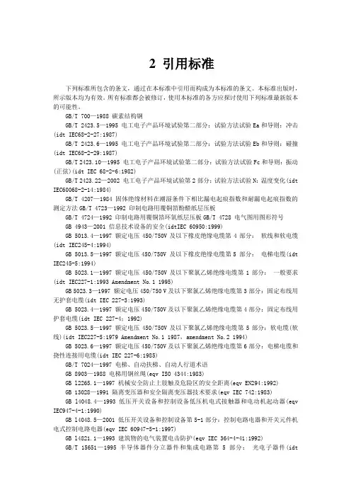
2 引用标准下列标准所包含的条文,通过在本标准中引用而构成为本标准的条文。
本标准出版时,所示版本均为有效。
所有标准都会被修订,使用本标准的各方应探讨使用下列标准最新版本的可能性。
GB/T 700—1988 碳素结构钢GB/T 2423.5—1995 电工电子产品环境试验第二部分:试验方法试验Ea和导则:冲击(idt IEC68-2-27:1987)GB/T 2423.6—1995 电工电子产品环境试验第二部分:试验方法试验Eb和导则:碰撞(idt IEC68-2-29:1987)GB/T 2423.10—1995 电工电子产品环境试验第二部分:试验方法试验Fc和导则:振动(正弦)(idt IEC 68-2-6:1982)GB/T 2423.22—2002 电工电子产品环境试验第2部分:试验方法试验N:温度变化(idt IEC60068-2-14:1984)GB/T 4207—1984 固体绝缘材料在潮湿条件下相比漏电起痕指数和耐漏电起痕指数的测定方法GB/T 4723—1992 印制电路用覆铜箔酚醛纸层压板GB/T 4724—1992 印制电路用覆铜箔环氧纸层压板GB/T 4728 电气图用图形符号GB 4943—2001 信息技术设备的安全(idtIEC 60950:1999)GB 5013.4—1997 额定电压450/750V及以下橡皮绝缘电缆第4部分:软线和软电缆(idt IEC245-4:1994)GB 5013.5—1997 额定电压450/750V 及以下橡皮绝缘电缆第5 部分:电梯电缆(idt IEC245-5:1994)GB 5023.1—1997 额定电压450/750V及以下聚氯乙烯绝缘电缆第1部分:一般要求(idt IEC227-1:1993 Amendment No.1 1995)GB 5023.3—1997 额定电压450/750 V及以下聚氯乙烯绝缘电缆第3部分:固定布线用无护套电缆(idt IEC 227-3:1993)GB 5023.4—1997 额定电压450/750V及以下聚氯乙烯绝缘电缆第4部分:固定布线用护套电缆(idt IEC 227-4;1992)GB 5023.5—1997 额定电压450/750V及以下聚氯乙烯绝缘电缆第5部分:软电缆(软线)(idt IEC227-5:1979 Amendment No.1 1987,amendment No.2 1994)GB 5023.6—1997 额定电压450/750V及以下聚氯乙烯绝缘电缆第6部分:电梯电缆和挠性连接用电缆(idt IEC 227-6:1985)GB/T 7024—1997 电梯、自动扶梯、自动人行道术语GB 8903—1988 电梯用钢丝绳(eqv ISO 4344:1983)GB l2265.1—1997 机械安全防止上肢触及危险区的安全距离(eqv EN294:1992)GB 13028—1991 隔离变压器和安全隔离变压器技术要求(eqv IEC 742:1983)GB l4048.4—1993 低压开关设备和控制设备低压机电式接触器和电动机起动器(eqv IEC947-4-1:1990)GB l4048.5—2001 低压开关设备和控制设备第5-1部分:控制电路电器和开关元件机电式控制电路电器(eqv IEC 60947-5-1:1997)GB l4821.1—1993 建筑物的电气装置电击防护(eqv IEC 364-4-41:1992)GB/T 15651—1995 半导体器件分立器件和集成电路第 5 部分:光电子器件(idtIEC747-5:1992)GB/T 16261—1996 印制板总规范(idt IEC/PQC 88:1990)GB/T 16856—1997 机械安全风险评价的原则GBl6895.3—1997 建筑物电气装置第5部分:电气设备的选择和安装第54章:接地配置和保护导体(idt IEC 364-5-54:1980)GB/T 16935.1—1997 低压系统内设备的绝缘配合第一部分:原理、要求和试验(idt IEC664-1:1992)JG/T 5072.1—1996 电梯T型导轨GA 109—1995 电梯层门耐火试验方法EN 12015:1998 电磁兼容性用于电梯、自动扶梯和自动人行道的产品系列标准辐射(Electromagnetic compatibility—Product family standard for lifts , escalators and passenger conveyors—Emission)EN 12016:1998 电磁兼容性用于电梯、自动扶梯和自动人行道的产品系列标准抗干扰性(Electromagnetic compatibility—Product family standard for lifts , escalators and passenger conveyors——Immunity)HD 384.6.61S1 建筑物的电气安装第6部分:验证第61章:初校验(Electrical installations Of building—Part 6;Verification—Chapter 61:Initial verification)3 定义本标准采用GB/T 7024中的术语及下列定义:3.1 曳引驱动电梯traction drive lift提升绳靠主机的驱动轮绳槽的摩擦力驱动的电梯。

77B/426/FDISFINAL DRAFT INTERNATIONAL STANDARD INTERNATIONAL ELECTROTECHNICAL COMMISSIONCOMMISSION ÉLECTROTECHNIQUE INTERNATIONALETHIS DOCUMENT IS A DRAFT DISTRIBUTED FOR APPROVAL. IT MAY NOT BE REFERRED TO AS AN INTERNATIONAL STANDARD UNTIL PUBLISHED AS SUCH.IN ADDITION TO THEIR EVALUATION AS BEING ACCEPTABLE FOR INDUSTRIAL, TECHNOLOGICAL, COMMERCIAL AND USER PURPOSES, FINAL DRAFT INTERNATIONAL STANDARDS MAY ON OCCASION HAVE TO BE CONSIDERED IN THE LIGHT OF THEIR POTENTIAL TO BECOME STANDARDS TO WHICH REFERENCE MAY BE MADE IN NATIONAL REGULATIONS.CE DOCUMENT EST UN PROJET DIFFUSÉ POUR APPROBATION. IL NE PEUT ÊTRE CITÉ COMME NORME INTERNATIONALE AVANT SA PUBLICATION EN TANT QUE TELLE.OUTRE LE FAIT D'ÊTRE EXAMINÉS POUR ÉTABLIR S'ILS SONT ACCEPTABLES À DES FINS INDUSTRIELLES, TECHNOLOGIQUES ET COMMERCIALES, AINSI QUE DU POINT DE VUE DES UTILISATEURS, LES PROJETS FINAUX DE NORMES INTERNATIONALES DOIVENT PARFOIS ÊTRE EXAMINÉS EN VUE DE LEUR POSSIBILITÉ DE DEVENIR DES NORMES POUVANT SERVIR DE RÉFÉRENCE DANS LES RÈGLEMENTATIONS NATIONALES.TitleIEC 61000-4-6 Am. 1 Ed. 2: Electromagnetic compatibility (EMC) - Part 4-6: Testing and measurement techniques - Immunity to conducted disturbances, induced by radio-frequency fieldsAmendment to IEC 61000-4-6: Define a new set-up for large EUTsTitreCEI 61000-4-6 Am. 1 Ed. 2: Compatibilité électromagnétique (CEM) - Partie 4-6:Techniques d'essai et de mesure - Immunité aux perturbations conduites, induites par les champs radioélectriquesAmendement à la CEI 61000-4-6 – Montage d’essai pour grands ESTFORM FDIS (IEC)/FORMULAIRE FDIS (CEI) Copyright © 2004 International Electrotechnical Commission, IEC . All rights reserved. It is permitted to download this electronic file, to make a copy and to print out the content for the sole purpose of preparing National Committee positions. You may not copy or "mirror" the file or printed version of the document, or any part of it, for any other purpose without permission in writing from IEC.FOREWORDThis amendment has been prepared by subcommittee 77B: High frequency phenomena, of IEC technical committee 77: Electromagnetic compatibility.The text of this amendment is based on the following documents:FDIS Report on voting77B/XX/FDIS 77B/XX/RVDFull information on the voting for the approval of this amendment can be found in the report on voting indicated in the above table.The committee has decided that the contents of this amendment and the base publication will remain unchanged until the maintenance result date1) indicated on the IEC web site under "http://webstore.iec.ch" in the data related to the specific publication. At this date, the publication will be• reconfirmed,• withdrawn,• replaced by a revised edition, or• amended._____________Page 3CONTENTSAdd, after Annex E, the following new Annex F:Annex F (informative) Test set-up for large EUTsPage 91Add, after Annex E, the following new Annex F:___________1)The National Committees are requested to note that for this publication the maintenance result date is 2010.Annex F(informative)Test set-up for large EUTsF.0 IntroductionThe test set-up as described in the main body of the standard (see Clause 7) is not fully sufficient to cover the needs of some large EUTs with cables entering or exiting the EUT at heights greater than 1 m. As the upper frequency of the test signal is 80 MHz, EUT size may be considerable compared to the wavelength, and resonance effects may be present with cables that are connected to such EUTs.In this case, this annex provides an alternative test method applicable to large EUTs that places the coupling device near to the cable entry, resulting in a small loop area with reduced resonance effects.Examples of large EUTs to which this annex may apply include, but are not limited to, the following.– rack-mounted telecommunication switching systems;– electrical machinery;– rack-mounted switch and control gear.F.1 Test set-up for large EUTsExamples of the test set-up for large EUTs are given in Figures F.1 and F.2.The elevated ground reference plane shown in Figure F.1 is the reference ground plane for this test set-up. The purpose of the elevated ground reference plane is to reduce the length of cable between the EUT and CDN, thereby controlling or reducing the effects of resonances in the cables.The size of the elevated ground reference plane shall be large enough to extend a minimum of 0,2 m beyond all CDNs used in the test. The length of cable under test between the EUT and CDN shall be a maximum 0,3 m.The elevated ground reference plane shall be placed at a height above the main ground plane so that to allow cables from the EUT to pass to the CDNs in a horizontal alignment.The elevated ground reference plane shall be electrically connected to earth for safety reasons. This connection is not significant from an RF point of view.NOTE 1 Attention should be taken with the physical construction of the elevated ground reference plane and its support structure to ensure a mechanically safe condition.The equipment to be tested should be placed on an insulating support of 0,1 m height above the ground plane. In case the equipment is delivered on a transport pallet, and if due to its excessive weight or size it cannot be safely removed from its transport pallet, then the EUT may be left on its pallet for testing even if its height exceeds 0,1 m. In case the equipment, because of size or weight, cannot be elevated 0,1 m, thinner insulation may be used provided the EUT is electrically isolated from the ground plane. Any variation from the standard method of testing shall be recorded in the test report.The AE may be located on the elevated ground reference plane but does not need to be located on it provided the AE is connected to the EUT via a CDN. When direct injection is used, the AE may be located off of the elevated ground reference plane provided proper decoupling is used. In the case where clamp injection is used instead of injection via a CDN, the AE must be located on the elevated ground reference plane.Figure F.1 – Example of large EUT test set-upwith elevated horizontal ground reference planeThe vertical ground reference plane shown in Figure F.2 is the reference ground plane for this test set-up. The purpose of the vertical ground reference plane is to reduce the length of cable between the EUT and CDN, thereby controlling or reducing the effects of resonances in the cables.NOTE 2 The vertical ground reference plane may be more applicable than the horizontal elevated ground reference plane in cases where cables enter/exit the EUT at multiple heights.The vertical ground reference plane shall be electrically connected to earth for safety reasons. This connection is not significant from an RF point of view.The size of the vertical ground reference plane shall be large enough to extend a minimum of 0,2 m beyond all CDNs used in the test. The length of cable under test between the EUT and CDN shall be a maximum 0,3 m. The distance between the EUT and the vertical ground reference plane shall be such that the 0,3 m cable length requirement can be satisfied. A wall of a shielded room can be used as the vertical ground reference plane.The CDNs shall be mounted to the vertical ground reference plane at a height that allows cables from the EUT to pass to the CDNs in a horizontal alignment.The statements given for the test set-up using a horizontal elevated ground reference plane (i.e., insulating support and location of AE) apply for the test set-up using a vertical ground reference plane accordingly.Figure F.2 – Example of large EUT test set-up with vertical ground reference plane___________ISBN 2-8318-XXXX-XTypeset and printed by the IEC Central OfficeGENEVA, SWITZERLAND。

IEC 61000-4-6 是国际电工委员会(IEC)发布的一项标准,该标准属于IEC 61000 系列,专注于电磁兼容性(EMC)。
具体而言,IEC 61000-4-6 标准关注电磁干扰的抗扰度测试,主要用于评估电子设备在特定频率范围内的抗干扰能力。
以下是关于IEC 61000-4-6 的一些重要信息:
1. **标题:** IEC 61000-4-6 的完整标题是"Electromagnetic compatibility (EMC) - Part 4-6: Testing and measurement techniques - Immunity to conducted disturbances, induced by radio-frequency fields",翻译为"电磁兼容性(EMC)- 第4-6部分:测试和测量技术- 对由射频场引起的传导干扰的抗扰度"。
2. **目的:** 该标准的主要目的是规定用于评估电子设备对由射频场引起的传导干扰的抗扰度的测试和测量技术。
3. **测试方法:** 标准描述了一系列测试方法,包括将射频信号注入设备的传导导体(例如电缆)并测量设备对这种干扰的抗性的方法。
4. **频率范围:** IEC 61000-4-6 主要关注9 kHz 到80 MHz 的频率范围内的传导干扰。
5. **应用领域:** 该标准适用于各种电子设备,包括工业、科学、医疗和家用设备。
如果您需要详细了解IEC 61000-4-6 标准的内容,建议查阅该标准的最新版本或联系相关的标准化机构。
标准的内容可能随时间而有所修改和更新。

iec 61000-6-4-2011电磁兼容(emc) 第6-4 部分通用标准工业环境用发射标准【1. 引言】1.1 概述本文旨在介绍IEC 61000-6-4-2011电磁兼容(EMC)标准的第6-4部分,即工业环境用发射标准。
随着现代工业生产的发展与智能化程度的提高,电子设备和系统在工业环境中广泛应用。
然而,在这些复杂的环境下,各种电气设备之间可能会发生相互干扰的现象,对其正常运行造成影响。
为了解决这一问题,并保证工业环境中各类电子设备之间的相互兼容性,IEC(国际电工委员会)制定了一系列关于电磁兼容的标准。
其中,IEC 61000-6-4-2011是针对工业环境中电磁干扰发射水平的标准。
本文将详细介绍该标准的背景、应用领域以及相关要求。
1.2 文章结构本文主要分为五个部分:引言、IEC 61000-6-4-2011电磁兼容介绍、发射标准概述、IEC 61000-6-4-2011发射标准详解以及结论与建议。
在引言部分,将对本文的目的和结构进行说明;其后,在第二部分将介绍IEC 61000-6-4-2011标准的概要、背景以及应用领域;第三部分将对发射标准进行概述,包括定义、重要性以及在工业环境中的作用;随后,在第四部分将详细解读IEC61000-6-4-2011发射标准的内容,并探讨其发射限值要求解析、测量方法以及测试设备要求;最后,我们在第五部分总结对IEC 61000-6-4-2011发射标准的评价,并对未来工业环境下电磁兼容问题提出展望与建议。
1.3 目的本文旨在全面介绍IEC 61000-6-4-2011标准中关于工业环境用发射标准的内容。
通过深入了解该标准的定义、重要性和应用领域,读者能够更好地理解工业环境下电磁兼容问题,并掌握相关测试方法和设备要求。
本文还将对该标准进行评价与总结,并提供展望和建议,帮助读者更好地处理工业环境中可能出现的电磁兼容问题,以确保电子设备在工业环境中的正常运行。