SMC过滤器说明书
- 格式:pdf
- 大小:333.72 KB
- 文档页数:8
af4000-04过滤器说明书
1.AF4000-04单联件油水分离气源处理器型号含义:
AF4000-04是SMC型空气过滤器,4000表示外形的尺寸大小,-04表示它的接管口径是PT1/2,4000系列有杯防护罩。
2.共同规格:
① 保证耐压力:1.5Mpa{15.3kgf/cm}
② 高使用压力:1.0Mpa{10.2kgf/cm}
③ 环境及流体温度:5~60°C
④ 过滤孔径:5um
⑤ 杯材质:PC
⑥ 杯防护罩:无
⑦ 调压范围:0.05~0.85Mpa{0.51~8.7kgf/cm}
3.气源处理件的选择及使用要求:
① 根据管路通径、流量大小、调压及过滤精度等技术性能等参数选择系统所
需要的空气组合件;
② 空气过滤器的过滤精度有2um、5um、10um、20um、40um、70um、100um七种,可根据空气的质量要求选用合适的产品;
③ 在使用减压阀时,尽量避免使用调压范围的下限值,按使用压力的要求选
择合适的减压阀;
④ 安装顺序:从气源的流入端开始,一次连接空气过滤器、减压阀、油雾器,元件壳体上的箭头方向为气流方向,不可反接;
⑤ 空气过滤、油雾器必须竖直安装并使带有罩杯侧朝下;
⑥ 油雾器一旦逆流,就会造成内部零件损坏和发生危险,故应避免发生;
⑦ 安装连接时,避免将密封胶带、铁锈等杂质混入管路内。
编辑本段气源处
理件的使用及维护。


微孔过滤器ZG-10.0使用说明书制作单位:生产基地:公司:公司传真:邮 编:编制日期:目录一、 产品介绍 (3)二、产品特点 (3)三、滤芯的选择 (3)四、设备技术参数 (4)五、使用说明 (4)六、操作注意事项 (6)七、设备的维护与保养 (6)八、售后服务承诺 (7)九、合格证 (7)十、随机附件表 (8)一、产品介绍:本设备可用于食品、乳品、饮料、酒类、中药、化工行业的液体物料的气体的过滤..采用折叠式滤芯;折叠式滤芯是一种先进的固定型深层过滤芯;过滤公称精度范围可以从0.1μm直600.1μm..滤膜不受进料压力波动而影响过滤精度..其特有的低压差;高通量、良好的过滤精度能较低的经济费用成为取代线绕式、棉饼和纸板等非固定型过滤芯的新型滤芯而深受用户欢迎..二、产品特点:①化学相容性广、流通量大、压差低、使用寿命长..②过滤精度范围广、选择度大、可满足各种应用场合..③采用热熔工艺;牢固且无释放物污染产品..三、滤芯的选择:1、滤芯的用途很广泛;滤芯的品种、规格较多;选择型号是很重要的..根据用途可分为过滤液体和气体二种;规格大小可以分为5〃、10〃、20〃、30〃和40〃等..工作压力一般在0.1Mpa—0.4 Mpa..由于滤芯孔径不同;其流量也不尽相同;如0.2um—0.4 um过滤沌水的标准在300—500kg/h;如果要提高每小时的过滤量;则可以用多芯或20〃、30〃、40〃英寸组合;例如要过滤5t/h的无菌水;则可以选用0.2 um;30英寸7芯的过滤器..若过滤杂质多且有粘度;则应添加前置预过滤设备..气体的过滤与液体过滤稍有不同;它的过滤量以每分钟立方气体来计算..10英寸滤芯;孔径φ0.22 um;压力在0.12 Mpa;压差在0.01 Mpa时;流量为4-6m3/min;在发酵工业上广泛应用..2 、合适的滤芯;选用适当的孔径;若要除菌则选用0.2um-0.5um孔径的滤芯、药用针剂、抗菌素、血制品等用聚砜滤芯..如果要去除液体中的微粒;微生物和细菌大一些的离子、杂质;如白酒、黄酒、葡萄酒、口服液、可选用1-5um的孔径即可..过滤高温气体和发酵空气消毒气体要选用聚四氟乙烯滤芯..3 、不锈钢筒式过滤器;它内部装有不同孔径的滤芯..要达到精滤的目的;前期必须用预过滤设备生啤用硅藻土;纸板过滤机..药厂用板框、熔喷、绕线式;再用微孔除菌过滤芯;这样就能达到精滤的目的..4、一般用矿泉水、药用无菌水、电子工业集成电路用水、食品工业用高质量的水..筒式微孔过滤器设计时应成为一个独立的过滤系统;它可以带反冲洗;节省生产成本..5 、除了选择高质量的滤芯;还要选择高质量的过滤器;不锈钢加工是否精细;内外是否光洁;特别是插口处222、226、平口等三种形式是国际通用的;千万不能搞错;否则无法使用;或者由于加工粗糙;插上去起不到密封过滤的效果..注:在使用不锈钢外壳时要注意过滤液体对不锈钢是否有腐蚀作用;不适用的应选用其它材料的过滤器..四、设备技术参数:五、使用说明:1、安装底座:安装前看清进、出口方向..液体应从滤芯外部流向中心;与滤芯插口相通的管道是出口..在滤器管道上有箭头标示流向;切勿接错..2 、安装滤芯:222插口为插入式;226插口为卡入式..如果是多芯应将压板套在翅片上;将螺栓适度拧紧滤芯在高温下会受热伸长;若压板过紧;滤芯无伸长空间会产生扭曲变形影响过滤精度..3 、装好外罩并与底座用卡箍单芯或螺栓多芯连接密封好;注意密封垫要放置平整;检查密封处无渗漏..4 、滤器消毒:新过滤器使用前必须清洗干净..用于除菌的过滤器要杀毒消菌;消毒工作一般应在生产线进行;以免外界污染..现场蒸汽消毒应严格控制蒸汽压力与压差;避免因过高蒸汽压力和压差而损坏滤芯..5 、过滤液体时;应先打开过滤器顶部的排气阀;把筒内的气体排尽;让液体充满筒内;否则会影响流通量..6 、过滤介质流过滤器时会因受到阻力产生压力降即进入与流出时的压力差;为了克服这种阻力;保持足够的流量;必要时要有足够的工作压力..每种滤芯我们都给出了相应的温度、压力限定值;请用户按要求使用..为不使滤芯受到过大流量的冲击;开启阀门时一定要缓慢7 、自选泵配套使用时;请注意流量与压力要匹配..以选旋涡泵、输液泵等自吸泵为宜..8 、停机时应放光滤液;如果时间不长;可不必打开滤器;若时间较长;或滤液不宜长时间存放;则要清洗滤器或滤芯..六、操作主要事项:1 、过滤器使用前必须检查配件和密封圈是否安全;有无损坏;然后按要求把它装好..2、过滤器必须用清洁剂洗干净请不要用酸类清洗洗净后用高温蒸汽杀菌、消毒洗的过滤器进出口要包封好;避免污染..3 、安装时进出口不要接反;一般原则外进内出滤芯..4 、芯是生产厂家在洁净的生产厂房内用塑料袋封装的;未使用切勿撕破塑料包装..使用要求较高的滤芯;应先测气泡点检查滤芯完整性;安装好后要经过高温蒸汽杀菌消毒..5 、入口时;一定要垂直;插入时先用无菌水或经过过滤的滤液湿润一下密封圈;以减少插入时的摩擦阻力..222滤芯插入口后;再用压板扣住尖端翅片;拧紧螺丝不动即可..226接口的滤芯插入后;应选90度卡紧;如果有一点不小心;就会达不到密封;容易漏水而达不到您的使用要求..6、过滤的液体进入时;应打开过滤器上面的放气阀;让液体充满滤器内;否则将影响过滤效果..7、筒体的压力表是显示过滤气内液体的压力;如果是二级过滤;第一道过滤器压力表指数稍小一些是正常现象;随着使用时间的增长;他们的压差会增大;流速减少;这说明滤芯孔隙大多已被堵塞;就要清洗或更换滤芯..8 、在过滤时;使用的压力一般在0.1Mpa左右;能满足生产需要就可以了;随着时间与流量的增加;滤芯微孔被堵塞;压力将会增加;一般不要超过0.3Mpa;最告绝对不能超过0.5Mpa..否则滤器滤芯将会被击穿;发生意外事故;如果确定在0.5Mpa以上的可以与我们联系;我们将根据您的要求为您另外加工..9 、反冲洗滤芯;一定要用无菌水;否则会污染滤芯;反冲洗方法..原出口变进口;把无菌水反方向打进要注意关闭原液过滤管道;打开排污口;操作人员看到滤液明显好转为宜..10、滤芯不用时;应尽量把滤液放光;滤液不宜隔夜存放..停机时间不长时一般不要打开滤器;不要拔掉滤芯;停机时间长;在再次使用前一定要清洗滤芯和滤器也可以用反冲方法进行冲洗..11、我公司生产的滤芯耐温一般在25℃--50℃为宜.长期操作温度应控制在60℃以下;消毒温度121℃以下30分钟;如果操作温度较高;则可以用内衬不锈钢的增强聚四氟乙烯滤芯.12、如果要过滤化学溶剂和高浓度化学品可详见滤芯使用说明书;或者与我公司联系用特殊滤芯来解决..13、若是自选配套使用;则要注意需要的流量、压力及泵的扬程要匹配;一般选用旋涡泵;输液泵等为宜;材料为304或316L不锈钢;端面选用机械密封..七、设备的维护与保养:1、长期停用的过滤器;必须把滤器内外清洗干净;滤芯取下;洗净烘干;用塑料袋封口存放;以免损坏..清洗剂请勿用盐酸类腐蚀性物质;温度不宜过高防止聚丙烯发生变形..存放时避免污染与撞击..2、下来的滤芯若应浸泡在酸碱洗液里;浸泡时间不得超过24小时;酸碱液温度一般在20℃--25℃..建议酸或碱与水的比例是20%为好..最后用无离子水反复冲洗..蛋白质含量较商的滤液;滤芯最好用酶溶液浸泡清洗效果好;重新再使用时;使用前一定要先清洗干净;然后再用蒸气消毒..3、滤芯消毒时要注意掌握时间和温度;聚丙烯在高温消毒柜里以121℃为宜;用蒸汽消毒在0.1 Mpa蒸汽汽压力下;以130℃/20分钟为宜;聚砜和聚四氟乙烯用蒸汽消毒时可以达到142℃;压力0.28Mpa;时间在30分钟左右为宜;如果温度过高;时间过长;压力过大;则会损坏滤芯..八、售后服务承诺:1)及时向需方提供按合同规定的全部技术资料各图纸;有义务在必要时邀请需方参与供方的技术设计审查..2)按需方要求的时间到现场进行技术服务;指导需方按供方的技术资料各图纸要求进行安装、分部与整套试运及试生产..3)对于需方选购的与合同设备有关的配套设备;供方应主动提供满足设备接口要求的技术条件各资料..4)严格执行供需双方就有关问题如开会议的纪要或签订的协议..5)根据需方的要求为需方举办有关设备安装、调试、使用、维护技术的业务培训;保证需方运行、维修人员熟练掌握运行各维修技能..6)加强售前、售中、售后服务;把“24小时服务”;“超前服务”;“全过程服务”;“终身服务”贯彻在产品制造;安装、调试、大修的全过程..7)接到需方反映的质量问题信息后;在24小时之内做出答复或派出服务人员;尽快到达现场;做到用户不满意;服务不停止..8)随时满足需方对备品备件的要求..9)无论在何种情况下;供方决不以任何理由刁难需方..九、合格证十、随机附件表。
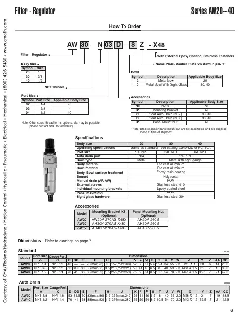
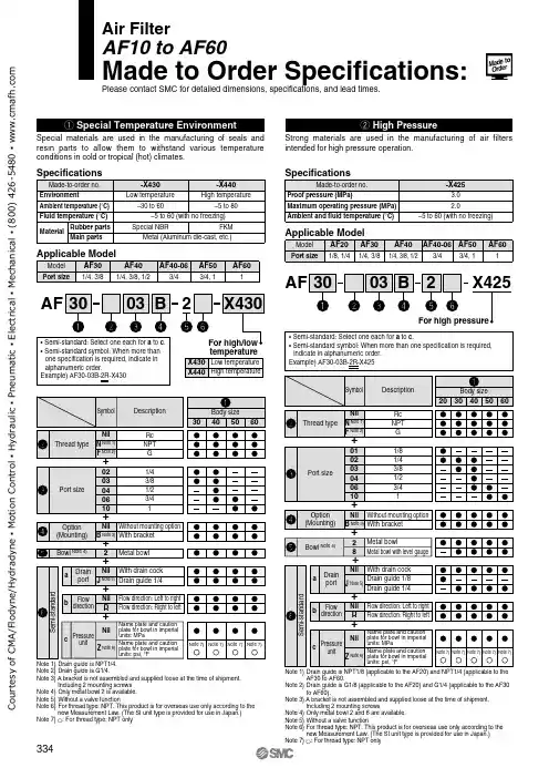
Series AW20~40Filter -RegulatorHow To OrderAW 30N 03D8Z -X48——Filter -Regulator Note:Other sizes,thread forms,options,etc.may be possible,please contact SMC for availability.With External Epoxy Coating,Stainless Fasteners Name Plate,Caution Plate On Bowl in psi,˚FNPT ThreadsBody SizeSymbol 203040Size 1/83/81/2Port SizeSymbol 020304Port Size 1/43/81/2Applicable Body Size203040SpecificationsBody sizeOperating specifications Port sizeAuto drain port Bowl type Body material Bowl materialBody,Bowl surface treatment BonnetManual drain (AF ,AW)External screwsIndividual mounting brackets Panel mount nutSight glass hardware203040Same as standard -see catalog ES40-42D or NC160A1/4”NPT N/A Metal 1/4”NPT Metal with sight gaugeDie cast aluminum Die cast aluminum Epoxy resin coatingPolyacetal POMStainless steel 410Epoxy coated steelPOMStainless steel 3043/8”NPT1/2”NPT BowlSymbol 28DescriptionMetal BowlMetal Bowl With Sight GlassApplicable Body Size 2030,40Accessories Symbol Nil B*C D H*Description None Mounting Bracket Float Auto Drain (N.C.)Float Auto Drain (N.O.)Panel Mount NutApplicable Body SizeAll All 30,4030,40AllAW30AW40A NPT 3/8NPT 1/2Dimensions Model Port Size C NPT 1/8NPT 1/4Gauge PortD 5370DD 34.541E 3038F 83(max.86)88(max.92)H3.51.5J 239(max.242)276(max.280)K 5975L 4150Q 4654S 6.58.5U 4054T 810.5V 5370W 2.32.3X M38X 1.5M42X 1.5Y 3135.5Z 77AA 1921CC 38.542.5AW20AW30AW40A NPT 1/4NPT 3/8NPT 1/2Dimensions Model Port Size C NPT 1/8NPT 1/8NPT 1/4Gauge PortD405370DD —34.541E —3038F 70(max.73)83(max.86)88(max.92)H 53.51.5J 157(max.160)218(max.221)255(max.259)K 525975L 304150Q 444654S 5.46.58.5U 344054T 15.4810.5AW20AW30AW40Mounting Bracket Kit(Optional)AW20P-270AS-X480AR30P-270AS-X480AR40P-270AS-X480Model V 555370W 2.32.32.3X M28X 1M38X 1.5M42X 1.5Y 303135.5Z 677AA 141921CC 28.538.542.5Panel Mounting Nut(Optional)AR20P-260S AR30P-260S AR40P-260SAuto DrainStandardAccessoriesDimensions -Refer to drawings on page 7mmmm *Note:Bracket and/or panel mount nut are not assembled and are suppliedloose at time of shipment.C o u r t e s y o f C M A /F l o d y n e /H y d r a d y n e ▪ M o t i o n C o n t r o l ▪ H y d r a u l i c ▪ P n e u m a t i c ▪ E l e c t r i c a l ▪ M e c h a n i c a l ▪ (800) 426-5480 ▪ w w w .c m a f h .c o mSeries AW20~40Filter -RegulatorStandard(ManualDrain)2-Bracket and (Optional )With AutoDrain2-Bracket and (Optional)Bowl Detail EE(AW20)Note:Sight glass not applicable to AW20.C o u r t e s y o f C M A /F l o d y n e /H y d r a d y n e ▪ M o t i o n C o n t r o l ▪ H y d r a u l i c ▪ P n e u m a t i c ▪ E l e c t r i c a l ▪ M e c h a n i c a l ▪ (800) 426-5480 ▪ w w w .c m a f h .c o m。
Instruction Manual Compact ManometerPPA100 / PPA101 / PPA102The intended use of this product is for pressure measurement.These safety instructions are intended to prevent hazardous situations and/or equipment damage. These instructions indicate the level of potential hazard with the labels of “Caution,” “Warning” or “Danger.”They are all important notes for safety and must be followed in addition to International Standards (ISO/IEC) *1), and other safety regulations. *1)ISO 4414: Pneumatic fluid power - General rules relating to systems. ISO 4413: Hydraulic fluid power - General rules relating to systems.IEC 60204-1: Safety of machinery - Electrical equipment of machines. (Part 1: General requirements)ISO 10218-1: Robots and robotic devices - Safety requirements for industrial robots - Part 1: Robots.• Refer to product catalogue, Operation Manual and Handling Precautions for SMC Products for additional information. • Keep this manual in a safe place for future reference.CautionCaution indicates a hazard with a low level of risk which, if not avoided, could result in minor or moderate injury.WarningWarning indicates a hazard with a medium level of riskwhich, if not avoided, could result in death or serious injury.DangerDanger indicates a hazard with a high level of risk which, ifnot avoided, will result in death or serious injury.Warning• Always ensure compliance with relevant safety laws and standards.• All work must be carried out in a safe manner by a qualified person in compliance with applicable national regulations.• Refer to the operation manual or catalogue on the SMC website (URL: https://) for further Safety Instructions.2 Specifications2.1General specificationsModelPPA100 High pressure PPA101 Vacuum PPA102 Low pressure Rated pressure range-0.1 to 1 MPa -101 to 10 kPa -10 to 100kPaDisplay method 3 digit LCD with backlight Pressure displaydiscrimination1/100Minimum display unit kPa - 1 1 MPa 0.01 - -mmHg- 5 - kgf/cm 20.1 0.01 0.01 inHg - 0.2 -psi 1 0.1 0.1 bar 0.1 0.01 0.01Error displayOver pressure, Memory data error,Change battery signFunctionPeak / bottom display, backlight, Auto powerOFF, Zero clear, Units display switchingWithstand pressure 1.5 MPa 200 kPa 200 kPa Applicable fluid Air, Non-corrosive gases, non-flammable gas Power supply voltage 3 VDC, Type AA dry cell x 2 pcs.Battery life12 months continuous operation(without backlight, at 25°C)Response speed 250 ms Display accuracy ±2% F.S. (at 25°C) Repeatability ±1% F.S. (at 25°C) Temperaturecharacteristics±3% F.S. (0 to 50°C with 25°C standard)Connection port size M5 x 0.8 Operatingtemperature range 0 to 50°C (no condensation)Operating humidityrange35 to 85% RH (no condensation)Enclosure rating IP40 Weight 100 g (Unit: 50 g, Battery: 50 g) *1) Batteries (manganese R6 or alkaline LR6) not included.*2) For the type without the unit switching function are fixed to SI units (kPa or MPa.*3) With regard to the compatibility condition for EMC, the pressure display value variation is ±15% F.S. or less.WarningSpecial products (-X) might have specifications different from those shown in this section. Contact SMC for specific drawings.3 Installation3.1 InstallationWarning• Do not install the product unless the safety instructions have been read and understood.3.2 EnvironmentWarning• Do not use in an environment where corrosive gases, chemicals, salt water or steam are present.• Do not use in an explosive atmosphere.• Do not expose to direct sunlight. Use a suitable protective cover.• Do not install in a location subject to vibration or impact in excess of the product’s specifications.• Do not operate in a location exposed to radiant heat that would result in temperatures in excess of the product’s specifications.3.3 PipingCaution• Before connecting piping be sure to clean up chips, cutting oil, dust etc. • When installing piping or fittings, ensure sealant material does not enter inside the port. When using seal tape, leave 1 thread exposed on the end of the pipe/fitting.• Tighten fittings to the specified tightening torque.3.4 LubricationCaution• SMC products have been lubricated for life at manufacture, and do not require lubrication in service.• If a lubricant is to be used in the system, refer to catalogue for details.4 Settings4.1 Initial SettingPerform initial setting when using for the first time and after changing the batteries, as the unit will display a memory data error.1. Confirmation of displayWhen power is applied, if there is nothing on the display, proceed to step 2.If “Err” Is displayed on the LCD, switch the power OFF and ON again. The display should clear. Proceed to step 2.2. Press and hold the POWER button for 6 seconds or more.The unit will move into the zero-clear mode. When this happens “CAL” will be displayed.3. Release the POWER button.When zero clear is finished, the unit will operate.4.2 Power ONPress the POWER button. The power will turn ON.When pressed and held for 6 seconds or more the unit will move into zero-clear mode.4.3 Power OFFPress and hold the POWER button for 3 seconds or more.The power will turn OFF.The power will also turn OFF If there is no button operation for 5 minutes or more (auto power OFF function).4.4 Units Display Switching1. Press and hold the POWER and LIGHTbuttons for 3 seconds or more.The units on the LCD display will flash.2. Press the LIGHT buttonThe units will change (refer to the units table).3. Press the POWER buttonThe units are set and the units display setting is complete.(For products with units switching function).Units availableHigh pressure (PPA100) Vacuum pressure(PPA101) Low pressure (PPA102) MPa > bar > psi > kgfkPa > bar > psi > inHg > mmHgkPa > bar > psi > kgf4.5 Peak / Bottom displayPress the POWER button. • For Peak displayTo display the maximum pressure value, with “P” displayed on the LCD. The display will change if the pressure exceeds the pressure being held.Press the POWER button. • For Bottom displayTo display the minimum pressure value, with “b” displayed on the LCD. The display will change if the pressure falls below the pressure being held. Press the POWER to complete the setting.Since this function is combined with the power OFF operation, the button should be released when the “P” or “b” is displayed.4.6 Auto Power OFF functionThe power is turned OFF when there has been no button operation for 5 minutes.(To cancel this function refer to the lock mode function below).4.7 Lock mode functionPress and hold the POWER and LIGHT buttons for 6 seconds or more.The lock mode is activated and the auto power OFF function is cancelled.“L” is displayed on the LCD display.When the power is turned OFF the lock mode is released.4.8 Turning ON the BacklightPress the LIGHT button.The display lights up when the button is pressed. In lock mode it lights up when pressed and turns OFF when pressed again.However the maximum lighting time is approximately one minute.4.9 Zero clear functionPress the POWER button for 6 seconds or more.The zero displayed at atmospheric pressure can be automatically adjusted.This means it is possible to eliminate a display discrepancy at atmospheric pressure. 1. Turn the power OFF.2. Release the supply pressure to atmosphere.3. When the POWER button is pressed and held for 6 seconds or more the zero clear function is performed and “CAL” is displayed on the LCD.ORIGINAL INSTRUCTIONSRefer to the operation manual or catalogue on the SMC website (URL: https:// ) for the How to Order information.Refer to the operation manual or catalogue on the SMC website (URL: https:// ) for outline dimensions.7.1 General maintenanceCaution•Not following proper maintenance procedures could cause the productto malfunction and lead to equipment damage.• If handled improperly, compressed air can be dangerous.Maintenance of pneumatic systems should be performed only by qualified personnel.• Before performing maintenance, turn off the power supply and be sure to cut off the supply pressure. Confirm that the air is released to atmosphere.• After installation and maintenance, apply operating pressure and power to the equipment and perform appropriate functional and leakage tests to make sure the equipment is installed correctly.• If any electrical connections are disturbed during maintenance, ensure they are reconnected correctly and safety checks are carried out as required to ensure continued compliance with applicable national regulations.• Do not make any modification to the product.• Do not disassemble the product, unless required by installation or maintenance instructions. 7.2 Span calibrationWarning• Do not touch the span calibration trimmer except when performing a span calibration.1. Perform zero clear at atmospheric pressure.2. Apply the maximum rated pressure and calibrate the span while comparing with a standard pressure gauge.3. If the displayed value of the compact manometer is “0” after returning to atmospheric pressure, then calibration is complete. If the displayed value is not “0” calibrate again by repeating steps 1 and 2.7.3 Replacing the batteriesWhen the battery voltage becomes low the entire LCD display will flash. When the LCD is flashing, replace the batteries. Use 2 x AA dry cell batteries.Caution• To replace the batteries, turn OFF the power and replace them within approximately 30 seconds.• If not completed within 30 seconds “Err” will be displayed. • In that case perform zero clear once again.• In the event that the display runs out of control, remove the batteries for one minute or longer and then perform zero clear again before inserting the batteries and turning ON the power.8.1 Limited warranty and disclaimer/compliance requirements Refer to Handling Precautions for SMC Products.This product shall not be disposed of as municipal waste. Check your local regulations and guidelines to dispose of this product correctly, in order to reduce the impact on human health and the environment.10 ContactsRefer to or www.smc.eu for your local distributor / importer.URL: https:// (Global) https://www.smc.eu (Europe) SMC Corporation, 4-14-1, Sotokanda, Chiyoda-ku, Tokyo 101-0021, Japan Specifications are subject to change without prior notice from the manufacturer. © 2021 SMC Corporation All Rights Reserved. Template DKP50047-F-085M。

C o a l e s c e rSpecificationsPort Sizes 1/4"Thread Styles NPT,BSPT,BSPP Flow Capacity 20 SCFM @ 100 PSI Bowl Types Aluminum PolycarbonateMaximum Temp.Aluminum 175°F,200 PSIG & Pressure*Polycarb.125°F,150 PSIG Filter Capacity0.01 Micron and LargerDifferential Pressure < 5.0 PSID at Rated Flow*For higher pressure applications, consult factory. If unit is equipped with differential indicator, maximum temperature and pressure are 125°F and 150 PSIG regardless of bowl design.Front ViewPhysical DimensionsModel #DescriptionA B C D 3P-020-M02-DCP Metal Bowl,Manual Drain 7.0 6.8 3.0 1.53P-020-M02-DC Metal Bowl,Float Drain7.0 6.8 3.0 1.53P-020-M02-DCi Metal Bowl,Float Drain w/Indicator 7.07.5 3.0 1.53P-020-P02-DCPPoly Bowl,Manual Drain 7.0 6.8 3.0 1.53P-020-P02-DC Poly Bowl,Float Drain7.0 6.8 3.0 1.53P-020-P02-DCiPoly Bowl,Float Drain w/Indicator7.07.53.01.5Order GuideMetal Bowl Poly Bowl Port SizeMetal Bowl w/Indicator Poly Bowlw/IndicatorManual Drain 1/4"3P-020-M02-DCP 3P-020-M02-DCPi 3P-020-P02-DCP 3P-020-P02-DCPiFloat Drain1/4"3P-020-M02-DC3P-020-M02-DCi3P-020-P02-DC 3P-020-P02-DCiReplacement Parts & AccessoriesDescription Part Number Bowl O-Ring N32-95-009Metal Bowl Assembly,N32-95-950Plastic Float Drain Differential Indicator N32-W1-DPi Manual Drain N32-95-182Brass Float Drain N32-95-978Plastic Float DrainN32-95-973Description Part Number Stage 1 Element 3P-020Blanking Cap N32-95-020Stage 2 Element 3C-020Manual Flex Drain N32-95-610Low Flow Plastic Drain N32-96-400Poly Bowl,Plastic Float DrainN32-15-160Side ViewC o a l e s c e rSpecificationsPort Sizes 1/4",3/8",1/2"Thread Styles NPT,BSPT,BSPP Flow Capacity 60 SCFM @ 100 PSI Bowl Types Aluminum PolycarbonateMaximum Temp.Aluminum 175°F,200 PSIG & Pressure*Polycarb.125°F,150 PSIG Filter Capacity0.01 Micron and LargerDifferential Pressure < 5.0 PSID at Rated Flow*For higher pressure applications, consult factory. If unit is equipped with differential indicator, maximum temperature and pressure are 125°F and 150 PSIG regardless of bowl design.Front ViewPhysical DimensionsModel #DescriptionA B C D 3P-060-M04-DCP Metal Bowl,Manual Drain 8.010.0 3.8 2.03P-060-M04-DC Metal Bowl,Float Drain8.010.5 3.8 2.03P-060-M04-DCi Metal Bowl,Float Drain w/Indicator 8.011.5 3.8 2.03P-060-P04-DCP Poly Bowl,Manual Drain 8.011.0 3.8 2.03P-060-P04-DCPoly Bowl,Float Drain8.010.5 3.8 2.03P-060-P04-DCiPoly Bowl,Float Drain w/Indicator8.011.53.82.0Order GuideMetal Bowl Poly Bowl Port Size Metal Bowl w/IndicatorPoly Bowlw/Indicator1/4"3P-060-M02-DCP 3P-060-M02-DCPi 3P-060-P02-DCP 3P-060-P02-DCPi Manual Drain3/8"3P-060-M03-DCP 3P-060-M03-DCPi 3P-060-P03-DCP 3P-060-P03-DCPi 1/2"3P-060-M04-DCP 3P-060-M04-DCPi 3P-060-P04-DCP 3P-060-P04-DCPi 1/4"3P-060-M02-DC 3P-060-M02-DCi 3P-060-P02-DC 3P-060-P02-DCi Float Drain3/8"3P-060-M03-DC 3P-060-M03-DCi 3P-060-P03-DC 3P-060-P03-DCi 1/2"3P-060-M04-DC3P-060-M04-DCi3P-060-P04-DC3P-060-P04-DCiReplacement Parts & AccessoriesDescription Part Number Bowl O-Ring N32-95-257Metal Bowl Assembly,N34-95-200Brass Float Drain Differential Indicator N32-W1-DPi Manual Drain (for Poly Bowl)N32-95-182Brass Float Drain N32-95-978Plastic Float Drain N32-95-9731st Stage Element3P-060DescriptionPart Number Blanking CapN32-95-020Manual Drain (for Metal Bowl)PC-022nd Stage Element 3C-060Poly Bowl,Flex Drain N32-95-610Poly Bowl,Brass Float Drain N32-15-164Poly Bowl,Plastic Float DrainN32-15-165Side ViewSpecificationsPort Sizes 1/2",3/4",1"Thread Styles NPT,BSPT,BSPP Flow Capacity 90 & 150 SCFM @ 100 PSI Bowl Types Aluminum PolycarbonateMaximum Temp.Aluminum 175°F,200 PSIG& Pressure*Polycarb.125°F,150 PSIG Filter Capacity0.01 Micron and LargerDifferential Pressure < 5.0 PSID at Rated Flow*For higher pressure applications, consult factory. If unit is equipped with differential indicator, maximum temperature and pressure are 125°F and 150 PSIG regardless of bowl design.Front ViewPhysical DimensionsModel #DescriptionA B C D 3P-090-M06-DCP Metal Bowl,Manual Drain 10.018.25 4.6 2.43P-090-M06-DC Metal Bowl,Float Drain10.017.5 4.6 2.43P-090-M06-DCi Metal Bowl,Float Drain w/Indicator 10.019.0 4.6 2.43P-090-P06-DCP Poly Bowl,Manual Drain 10.015.0 4.6 2.43P-090-P06-DC Poly Bowl,Float Drain10.014.5 4.6 2.43P-090-P06-DCiPoly Bowl,Float Drain w/Indicator10.015.04.62.4Physical dimensions for the 90 SCFM units are identical to the 150 SCFM units.Order GuideMetal Bowl Poly Bowl Port Size Metal Bowl w/IndicatorPoly Bowlw/Indicator1/2"3P-090-M04-DCP 3P-090-M04-DCPi 3P-090-P04-DCP 3P-090-P04-DCPi Manual Drain3/4"3P-090-M06-DCP 3P-090-M06-DCPi 3P-090-P06-DCP 3P-090-P06-DCPi 1"3P-090-M08-DCP 3P-090-M08-DCPi 3P-090-P08-DCP 3P-090-P08-DCPi 1/2"3P-090-M04-DC 3P-090-M04-DCi 3P-090-P04-DC 3P-090-P04-DCi Float Drain3/4"3P-090-M06-DC 3P-090-M06-DCi 3P-090-P06-DC 3P-090-P06-DCi 1"3P-090-M08-DC 3P-090-M08-DCi3P-090-P08-DC3P-090-P08-DCi1/2"3P-150-M04-DCP 3P-150-M04-DCPi 3P-150-P04-DCP 3P-150-P04-DCPi Manual Drain3/4"3P-150-M06-DCP 3P-150-M06-DCPi 3P-150-P06-DCP 3P-150-P06-DCPi 1"3P-150-M08-DCP 3P-150-M08-DCPi 3P-150-P08-DCP 3P-150-P08-DCPi 1/2"3P-150-M04-DC 3P-150-M04-DCi 3P-150-P04-DC 3P-150-P04-DCi Float Drain3/4"3P-150-M06-DC 3P-150-M06-DCi 3P-150-P06-DC 3P-150-P06-DCi 1"3P-150-M08-DC3P-150-M08-DCi3P-150-P08-DC3P-150-P08-DCiReplacement Parts & AccessoriesDescription Part Number Metal Bowl Assembly,N34-15-179Brass Float DrainDifferential Indicator N32-W1-DPi Manual Drain (for Poly Bowl)N32-95-182Brass Float Drain N32-95-978DescriptionPart Number 2nd Stage Element 3C-090,3C-150Blanking CapN32-95-020Manual Drain (for Metal Bowl)PC-03Bowl O-Ring N32-95-2561st Stage Element3P-090,3P-150Side ViewC o a l e s c e r。
SM-14S M C系列阀门电动装置使 用 说 明 书天津百利二通机械有限公司TIANJIN BAILI ERTONG MACHINERY CO.,LTD.目 录第一部分 SMC系列普通型产品使用说明第二部分 SMC系列整体型产品使用说明第三部分 SMC系列隔爆型产品使用说明第四部分 SMC-04~SMC-2低温型产品使用说明第一部分 SMC系列普通型产品使用说明1.概述SMC系列多回转型阀门电动装置(以下称电动装置)用于驱动控制阀瓣作直线运动的闸阀、截止阀、隔膜阀等多回转阀门。
SMC系列中的部分机座产品也可以同BA伞齿轮减速器或直齿轮减速器组合,形成SMC/BA等组合式多回转电动装置。
当SMC系列产品与HBC蜗轮减速器或JA行星减速器组合后则成为组合式部分回转电动装置,它用于驱动控制阀瓣作旋转运动的球阀、蝶阀、旋塞阀等部分回转阀门。
SMC系列电动装置可以远距离电动操作(控制室内操作),可以根据订货要求加装现场按钮灯盒,从而具备现场操作功能。
SMC系列产品的手动机构可完成现场手动操作阀门。
由于SMC/BA、SMC/HBC、SMC/JA等组合型式电动装置的控制、调节部件均在SMC系列产品上,所以本说明书同样适用于上述产品。
(图1)~(图9)所示为SMC、SMC/BA、SMC/HBC、SMC/JA普通型产品的外形主视图。
上述产品的外形和法兰连接尺寸可参见我公司有关产品样本。
所用电动装置的输出转矩、转速、转圈数、电动机功率等详见该电动装置的铭牌。
2.基本技术参数产品符合GB/T24923-2010《普通型阀门电动装置技术条件》2.1动力电源:380V、50Hz(特殊订货可提供220V、415 V、440 V、460 V、480 V、660 V、690 V,50Hz、60Hz)三项正弦交流电(根据用户要求,某些规格可提供单相220V电源的电动机)。
2.2外壳保护等级:IP65~IP67(IP68订货时提出)2.3使用环境温度:-20℃~70℃(根据用户订货要求)2.4环境相对湿度:≤90%(25℃时)2.5海拔高度:≤1000m2.6短时工作:时间定额为10、15、30min(根据电动机负载情况而定)2.7无强烈振动工况。
Other SettingsSummary of Product partsSimple Setting ModeTroubleshootingNote: Specifications are subject to change without prior notice and any obligation on the part of the manufacturer.© 2015 SMC Corporation All Rights ReservedAkihabara UDX 15F, 4-14-1, Sotokanda, Chiyoda-ku, Tokyo 101-0021, JAPANPhone: +81 3-5207-8249 Fax: +81 3-5298-5362URL Specifications/Outline with Dimensions (in mm)Refer to the product catalogue or SMC website (URL ) formore information about the product specifications and outline dimensions.PS※※-OMS0008-A InstallationMounting with bracketMount the bracket to the body with mounting screws (Self tapping screws:Nominal size 3 x 8L (2 pcs)), then set the body to the specified position.∗: Tighten the bracket mounting screws to a torque of 0.5±0.05 Nm.Self tapping screws are used, and should not be re-used several times.∗: The panel mount adapter can be rotated through 90 degrees for mounting.•Bracket A (Part No.: ZS-46-A1)•Bracket B (Part No.: ZS-46-A2)Mounting with panel mount adapterMount part (a) to the front of the body and fix it. Then insert the body with (a)into the panel until (a) comes into contact with the panel front surface. Next,WiringWiring connectionsConnections should be made with the power supply turned off.Use a separate route for the product wiring and any power or high voltagewiring. Otherwise, malfunction may result due to noise.If a commercially available switching power supply is used, be sure toground the frame ground (FG) terminal. If the switching power supply isconnected for use, switching noise will be superimposed and it will not beable to meet the product specifications. In that case, insert a noise filtersuch as a line noise filter/ferrite between the switching power supplies orchange the switching power supply to the series power supply.How to use connectorstraight out.OUT1NCNCDC(-)PipingTightening the connection threadFor connecting to the body (piping specification: -M5)After hand tightening, apply a spanner of the correctsize to the spanner flats of the piping body, and tightenwith a 1/6 to 1/4 rotation.As a reference, the tightening torque is 1 to 1.5 Nm.(When replacing the piping adapter ZS-39-N∗, tighten itusing the same method.)Piping specification: -01, -N01After hand tightening, hold the hexagonal spanner flatsof the pressure port with a spanner, and tighten with 2 to3 rotations.As a reference, the tightening torque is 3 to 5 Nm.When tightening, do not hold the Z/ISE20 body with aspanner.Default settingsWhen the pressure exceedsthe set value, the switch will beturned on. When the pressurefalls below the set value by theamount of hysteresis or more,the switch will be turned off.The default setting is to turn onthe pressure switch when thepressure reaches the centre of the atmospheric pressure and upper limit of therated pressure range. If this condition, shown to the right, is acceptable, then keepthese settings.Error indication functionThis function is to display error location and content when a problem or error has occurred.than above are displayed, please contact SMC.Refer to the SMC website (URL ) for more informationabout troubleshooting.button between1 and 3 sec.button between3 and 5 sec.∗:The outputs will continue to operate during setting.∗:If a button operation is not performed for 3 seconds during the setting, the display will flash.(This is to prevent the setting from remaining incomplete if, for instance, an operator were to leaveduring setting.)∗:3 step setting mode, simple setting mode and function selection mode settings are reflected eachother.[3 step setting mode (hysteresis mode)]orsetting can be changed in the same way.button once when the item toThe set value on the sub display (right) willstart flashing.orbutton and can be reduced withbutton.buttons are pressed and held simultaneously for 1second or longer, the set value is displayed as [- - -], and the set value will bethe same as the current pressure value automatically (snap shot function).button.button to complete the setting.The Pressure switch turns on within a set pressure range (from P1L to P1H) duringwindow comparator mode.Set P1L, the lower limit of the switch operation, and P1H, the upper limit of theswitch operation and WH1 (hysteresis) following the instructions given above.(When reversed output is selected, the sub display (left) shows [n1L] and [n1H].)∗:Setting of the normal/reverse output switching and hysteresis/window comparator modeswitching are performed with the function selection mode [F 1] OUT1 setting.valuePeak/bottom value indicationbutton inmeasurement mode.Snap shot functionbuttons for 1second or longer simultaneously. Then, the set value of the sub display (right)shows [- - -], and the values corresponding to the current pressure values areautomatically displayed.Zero-clear functionbuttons are pressed for 1 secondor longer simultaneously, the main display shows [- - -], and the reset to zero.The display returns to measurement mode automatically.Key-lock functionTo set each of these functions, refer to the SMC website(URL ) for more detailed information, or contact SMC.button between 1 and 3 seconds inmeasurement mode. [SEt] is displayed on the main display. Whenthe button is released while in the [SEt] display, the current pressurevalue is displayed on the main display, [P_1] or [n_1] is displayed onthe sub display (left), and the set value is displayed on the subdisplay (right) (Flashing).or button to set the(The snap shot function can be used.)or button to set the(The snap shot function can be used.)or button, the delay time of the switch output can be selected.button for 2 seconds or longer to complete the OUT1 setting.∗:If the button is pressed for less than 2 seconds, the setting will be returned to P_1.In the window comparator mode, set P1L, the lower limit of the switch operation,and P1H, the upper limit of the switch operation, WH1 (hysteresis) and dt1 (delaytime) following the instructions given above.(When reversed output is selected, the sub display (left) shows [n1L] and [n1H].)Function selection modebutton between 3 and 5seconds, to display [F 0]. Select todisplay the function to be changed[F]. Press and hold the buttonfor 2 seconds or longer in functionselection mode to return tomeasurement mode.∗:Some products do not have all the functions. If no function is available or selected due toconfiguration of other functions, [- - -] is displayed on the sub display (right).Names of individual partsRefer to the product catalogue or SMC website (URL )for more information about panel cut-out and mounting hole dimensions.Pressure Setting3 Step Setting Mode(URL ) for more detailed information, or contact SMC.MaintenanceHow to reset the product after a power cut or forcible de-energizingThe setting of the product will be retained as it was before a power cut orde-energizing. The output condition is also basically recovered to that before apower cut or de-energizing, but may change depending on the operatingenvironment. Therefore, check the safety of the whole installation before operatingthe product. If the installation is using accurate control, wait until the product haswarmed up (approximately 10 to 15 minutes).Safety InstructionsBefore UseDigital Pressure SwitchZSE20(F)/ISE20Thank you for purchasing an SMC ZSE20(F)/ISE20 Series Digital PressureSwitch.Please read this manual carefully before operating the product and make sure youunderstand its capabilities and limitations. Please keep this manual handy forfuture reference.Safety InstructionsThese safety instructions are intended to prevent hazardous situations and/orequipment damage.These instructions indicate the level of potential hazard with the labels of"Caution", "Warning" or "Danger". They are all important notes for safety and mustbe followed in addition to International standards (ISO/IEC) and other safetyregulations.OperatorSwitch ONAt normal output Switch OFFSet valueP_1HysteresisH_1TimePressureOther parameter settingsDefault settingThe default setting is as follows.If no problem is caused by thissetting, keep these settings.。
使用说明书SMC过滤器 (FGE 系列)FGES□-□-※A-□FGEL□-□-※A-□目 录● 安全注意事项 ・・・・・・・・・・・・・・・ P2、3 ● 各部分名称及其作用・・・・・・・・・・・・・・P4 ● 产品规格・・・・・・・・・・・・・・・・・・ P5 ● 安装、配管・・・・・・・・・・・・・・・・・ P5 ● 操作・・・・・・・・・・・・・・・・・・・・ P5 ・・・・・・・・・・・・・・・・P6、7 ●滤芯的更换方法SMC株式会社使用前请务必仔细阅读。
以下叙述注意事项的目的是为了让客户更安全的使用FGES、L 系列的产品并且在使用过程中事先预防会对您或他人带来的危害及伤害,以下所有安全事项都与安全息息相关,因此请您务必遵守每项内容。
操作不当可能会导致液体泄漏、本体盖脱落等异常,会导致意想不到的事故。
另外,机器适应性的决定应由知识和经验丰富的系统设计师来进行判断。
滤芯的破损防止、性能确保以及从定期维护的作业性考虑,请遵守下面所述注意事项。
使用条件设计以及安装时的注意点警告①使用压力・请不要超出使用压力范围。
②使用温度・请不要超出使用温度范围。
③使用流体・不要使用气体。
・不要使用具有腐蚀作用的流体。
・不要使用会对密封圈、O 型圈以及滤芯可能产生膨胀和劣化作用的流体。
④使用环境・请不要在可能会引起腐蚀的环境中使用。
・请不要在具有震动以及冲击的环境下使用。
操作上的注意事项警告①在加压的状态下千万不要松开V 型带。
②V 型带请正确安装在指定位置。
(请参考第7页) ③O 型圈若出现劣化、膨胀等异常时请及时更换。
O 型圈从使用即日起1年之后或者发生液体泄漏时要 进行更换。
(更换O 型圈请参考第4页表1) ④泵启动等加压过程,先开启上部抽气口后必须进行抽气。
⑤不要使用出现变形或螺纹损坏等异常现象的V型带(参考第4页表1)警告①清设计充分符合产品的安全要求的系统,如使用压力、使用温度、使用流体、使用环境等使用条件。
Other SettingsSummary of Product partsSimple Setting ModeTroubleshootingNote: Specifications are subject to change without prior notice and any obligation on the part of the manufacturer.© 2020 SMC Corporation All Rights ReservedAkihabara UDX 15F, 4-14-1, Sotokanda, Chiyoda-ku, Tokyo 101-0021, JAPANPhone: +81 3-5207-8249 Fax: +81 3-5298-5362URL https://Specifications/Outline with DimensionsRefer to the product catalog or SMC website (URL https://) for moreinformation about the product specifications and outline dimensions.PS※※-OMX0003 DC(+)OUT1NCNCDC(-)BrownBlackWhiteGrayBlueDefault settingsWhen the pressure exceeds the setvalue, the switch will be turned on.When the pressure falls below theset value by the amount ofhysteresis or more, the switch willbe turned off. The default setting isto turn on the pressure switch whenthe pressure reaches the centre ofthe atmospheric pressure and upper limit of the rated pressure range. If this condition,shown to the right, is acceptable, then keep these settings.Error indication functionThis function is to display error location and content when a problem or error has occurred.above are displayed, please contact SMC.Refer to the SMC website (URL https://) for more information abouttroubleshooting.button between3 and 5 sec.∗:The outputs will continue to operate during setting.∗:If a button operation is not performed for 3 seconds during the setting, the display will flash.(This is to prevent the setting from remaining incomplete if, for instance, an operator were to leave duringsetting.)∗:3 step setting mode, simple setting mode and function selection mode settings are reflected each other.[3 step setting mode (hysteresis mode)]orcan be changed in the same way.button once when the item to beThe set value on the sub display (right) will startflashing.orbutton and can be reduced with button.buttons are pressed and held simultaneously for 1 second orlonger, the set value is displayed as [- - -], and the set value will be the same as thecurrent pressure value automatically (snap shot function).Afterwards, it is possible to adjust the value by pressing button.button to complete the setting.The pressure switch turns on within a set pressure range (from P1L to P1H) duringwindow comparator mode.Set P1L, the lower limit of the switch operation, and P1H, the upper limit of the switchoperation and WH1 (hysteresis) following the instructions given above.(When reversed output is selected, the sub display (left) shows [n1L] and [n1H].)∗:Set OUT2 in the same way. (ex. P_2, H_2)∗:Setting of the normal/reverse output switching and hysteresis/window comparator mode switchingare performed with the function selection mode [F 1] OUT1 setting and [F 2] OUT2 setting.value[F 0] Display units, switch output specificationsand diagnostic information selection functionPeak/bottom value indicationThe value can be displayed on the sub display by pressing button inmeasurement mode.Snap shot functionbuttons for 1 secondor longer simultaneously. Then, the set value of the sub display (right) shows [- - -], andthe values corresponding to the current pressure values are automatically displayed.Zero-clear functionIn measurement mode, when the buttons are pressed for 1 second orlonger simultaneously, the main display shows [- - -], and the reset to zero.The display returns to measurement mode automatically.Key-lock functionTo set each of these functions, refer to the SMC website(URL https://) for more detailed information, or contact SMC.button between 1 and 3 seconds in measurementmode. [SEt] is displayed on the main display. When the button is releasedwhile in the [SEt] display, the current pressure value is displayed on themain display, [P_1] or [n_1] is displayed on the sub display (left), and theset value is displayed on the sub display (right) (Flashing).or button to(The snap shot function can be used.)or button to set the(The snap shot function can be used.)or button, the delay time of the switch output can be selected.button for 2 seconds or longer to complete the setting.∗:If the button is pressed for less than 2 seconds, the setting will moves to the OUT2 setting.In the window comparator mode, set P1L, the lower limit of the switch operation, andP1H, the upper limit of the switch operation, WH1 (hysteresis) and dt1 (delay time)following the instructions given above.(When reversed output is selected, the sub display (left) shows [n1L] and [n1H].)∗:Set OUT2 in the same way.Function selection modebuttonbetween 3 and 5 seconds, to display [F 0].Select to display the function to be changed[F button for 2seconds or longer in function selection modeto return to measurement mode.∗:Some products do not have all the functions. If no functionis available or selected due to configuration of otherfunctions, [- - -] is displayed on the sub display (right).Names of individual partsPressure Setting3 Step Setting Mode(URL https://) for more detailed information, or contact SMC.MaintenanceHow to reset the product after a power cut or forcible de-energizingThe setting of the product will be retained as it was before a power cut or de-energizing.The output condition is also basically recovered to that before a power cut or de-energizing, but may change depending on the operating environment. Therefore, checkthe safety of the whole installation before operating the product. If the installation is usingaccurate control, wait until the product has warmed up (approximately 10 to 15 minutes). Safety InstructionsBefore UseDigital Pressure SwitchZSE20C(F)-L/ISE20C(H)-LThank you for purchasing an SMC ZSE20C(F)-L/ISE20C(H)-L Series Digital PressureSwitch.Please read this manual carefully before operating the product and make sure youunderstand its capabilities and limitations. Please keep this manual handy for futurereference.Safety InstructionsThese safety instructions are intended to prevent hazardous situations and/orequipment damage.These instructions indicate the level of potential hazard with the labels of "Caution","Warning" or "Danger". They are all important notes for safety and must be followed inaddition to International standards (ISO/IEC) and other safety regulations.OperatorSwitch ONAt normal output Switch OFFSet valueP_1HysteresisH_1TimePressureDefault settingThe default setting is as follows.If no problem is caused by this setting,keep these settings.[F 1] Setting of OUT1[F 2] Setting of OUT2Same setting as [F 1] OUT1.InstallationMountingMount the optional bracket and panel mount adapter to the pressure switch.When the pressure switch is to be mounted in a place where water and dustsplashes occur, insert a tube into the air-relieving port of the pressure switch.(Refer to "Tube attachment")Mounting with bracketMount the bracket to the body with mounting screws(Self tapping screws), then set the body to the specified position.∗: Tighten the bracket mounting screws to a torque of 0.5±0.05 Nm.Self tapping screws are used, and should not be re-used several times.∗•Bracket A (Part No.: ZS-46-A1)•Bracket C (Part No.: ZS-46-E)<Rear piping><Bottom piping>WiringWiring connectionsConnections should be made with the power supply turned off.Use a separate route for the product wiring and any power or high voltage wiring.Otherwise, malfunction may result due to noise.If a commercially available switching power supply is used, be sure to ground theframe ground (FG) terminal. If the switching power supply is connected for use,switching noise will be superimposed and it will not be able to meet the productspecifications. In that case, insert a noise filter such as a line noise filter/ferritebetween the switching power supplies or change the switching power supply toHow to use connectorConnection using screw type fittingConnect suitable piping to the port.To connect the hexagon socket head plug or fitting to thepressure port, hold the hexagon part of the pressure port with asuitable spanner. Apply atightening torque of 8 to12 Nm.When tightening, do nothold the pressure switchbody with a spanner.Tube attachmentWhen this pressure switch is used in a place where water and dust splashes mayoccur, insert a tube in the air-opposite side up to the safe positionto keep it from water and dust.(See the right figure.)∗: The tube should be inserted to the end ofthe air-relieving port.∗: SMC TU0425 (polyurethane, O.D ø4, I.Dø2.5) is a suitable tubing.To the safe position to keep from water and dust。