TracePro官方例子中文版(翻译)---导光管
- 格式:pdf
- 大小:2.84 MB
- 文档页数:36
TracePro介绍TracePro基本信息TracePro是一套普遍用于照明系统、光学分析、辐射度分析及光度分析的光线模拟软件。
它是第一套以ACIS solid modeling kernel 为基本的光学软件。
第一套结合真实固体模型、强大光学分析功能、资料转换能力强及易上手的使用界面的模拟软件。
TracePro可利用在显示器产业上,它能模仿所有类型的显示系统,从背光系统,到前光、光管、光纤、显示面板和LCD投影系统。
优点比起传统的原形方法,TracePro在建立显示系统的原型时,在时间上和成本上要降低30-50%。
常建立的模型照明系统、灯具及固定照明、汽车照明系统(前头灯、尾灯、内部及仪表照明)、望远镜、照相机系统、红外线成像系统、遥感系统、光谱仪、导光管、积光球、投影系统、背光板。
功能TracePro作为下一代偏离光线分析软件,需要对光线进行有效和准确地分析。
为了达到这些目标,TracePro具备以下这些功能:处理复杂几何的能力,以定义和跟踪数百万条光线;图形显示、可视化操作以及提供3D实体模型的数据库;导入和导出主流CAD软件和镜头设计软件的数据格式。
使用在使用上,TracePro使用十分简单,即使是新手也可以很快学会。
TracePro使用上只要分5步:1、建立几何模型;2、设置光学材质;3、定义光源参数;4、进行光线追迹;5、分析模拟结果。
2应用范围编辑1. LED光源和LED照明.2. 日光灯、灯盘和栅格.3. 建筑和展示照明.4. 消费产品.5. 车灯和航空照明.6. 医疗设备和舞台照明.7. 运输和应急照明.。
Tracepro中⽂⼿册第六章第六章分析检验光线追迹结果完成光线追迹之后,当进⾏结果评估时,分析菜单提供多种⽅法来显⽰光线追迹数据。
Displaying Rays 和 Ray Sorting让你观察数据是否是你期待的结果。
Irradiance Maps, Ray Tables and Polarization Maps 提供每⼀个表⾯的模拟结果。
Candela Plots 显⽰模型中光线数据的⾓度分配。
Volume Flux Viewer能够观察模型内部的流量分布。
Reports Menu 帮助你完成分析光线数据和模型的多种报告形式。
Tools 菜单包括附加的功能来帮助你完成光线追迹结果。
Analysis Menu在本章中的描述中,⼤多数的光线追迹结果从Analysis Menu中得到,光线追迹也被包含在Analysis Menu项⽬的开始,这在第五章有详细地介绍。
Display RaysAnalysis | Display Rays 选项允许你控制光线的显⽰。
“Analysis Mode(分析模式)”下,在完成光线追迹后, 光线默认地被显⽰或取消。
光线在“Simulation Mode(模拟模式)”中不能够被显⽰。
要关闭显⽰的光线,只需进⼊Analysis | Display Rays,显⽰光线的状态是通过菜单上√ 标志来标注的。
如果被trace的光线有很多并且带有许多的splits or branches,程序会花很长时间来显⽰这些光线。
你可以根据需要设定Window|Auto Update来更新光线的显⽰,这时的光线不会被随时更新,直到你按“F5”或选择Window|Refresh。
光线也可能在和图画程序组合期间同步显⽰,当具有优先设置时。
参考2.43页的“Ray Display”。
你也可以按照下⾯的描述使⽤Ray Sorting来决定哪些光线显⽰。
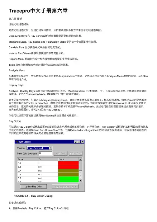
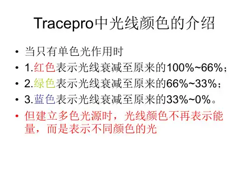
Ray Colors可以通过Ray Color对话框来设置光线的颜⾊来取代预先设值的颜⾊值,对于单⾊光,Ray Color对话框提供三种预设的颜⾊值来显⽰光线颜⾊。

TexturedRepTileBacklightRequirementsModels: NoneProperties: NoneEditions: TracePro ExpertIntroductionThere are a number of optical systems that use small, repeated optical geometry to perform. Examples include the structure for backlights, brightness enhancement films, and lenslet arrays. RepTile within TracePro allows repetitive structure to be placed on planar surfaces in a number of different patterns without the need to develop each one of the geometry elements. This not only saves time during the development phase, but also time during the ray trace analysis since the computation of intercepts with the RepTile geometry is computed analytically rather than through intersections with geometry. RepTile till now (i.e., prior to Version 4.0 of TracePro) has three cases:IntroductionThere是一个使用小型的光学系统,光学几何重复执行。

Tracepro 入门与进阶CYQ DESIGN STUDIO1Tracepro 入门与进阶CYQ DESIGN STUDIO内 容 简 介本书以美国 Lambda Research Corporation 的最新 3.24 版本为蓝本进行编写, 内容涵盖了 tracepro3.24 光学仿真设计的概念、tracepro 软件的配置和用户定制、光 学元件模型的创建、描光、分析等内容。
本书章节的安排次序采用由浅入深,前后呼应的教学原则,在内容安排上,为方 便读者更快、更深入地理解 tracepro 软件中的一些相关概念、命令和功能,并对运用 该软件进行光学仿真设计的过程有一个全局的了解,本书中介绍了单片 LCD 投影机 的仿真设计全过程,同时在本书的最后一章详细介绍了背光源等光学仿真设计过程, 增强了本书的可读性和实用性,摆脱单个概念、命令、功能的枯燥讲解和介绍。
本书可作为光学专业人员的自学教程和参考书籍, 也可作为大专院校光学、 光电专业 的学生学习 tracepro 的使用教材。
2Tracepro 入门与进阶CYQ DESIGN STUDIO前言Tracepro 是一套可以做照明光学系统分析、传统光学分析,辐射度以及光度分析 的软件, 它也是第一套由符合工业标准的 ACIS 立体模型绘图软件发展出来的光机软 件。
功能强大的 Tracepro 减轻了光学设计人员的劳动强度,节约了大量的人力资源, 缩短了设计周期,还可以开发出更多质量更高的光学产品。
但目前 Tracepro 学习教 程甚少, 不少初学者苦于无参考学习资料而举步为艰。
本人根据从事光学设计的经验 与运用 Tracepro 的体会,汇集成书,目的是使 Tracepro 的初学人员能快速入门,快 速见效,使已入门者能进一步提高 Tracepro 的应用水平和操作能力,从而在工作中 发挥更大的效益,为中国的光学事业作出贡献! 本书乃仓促而成,虽然几经校对,但错误之处在所难免,恳请广大读者朋友予以 指正,不甚感谢! 电子邮箱: cyqdesign@陈涌泉 2004 年 12 月 4 日3Tracepro 入门与进阶CYQ DESIGN STUDIO目录第一章 TracePro3.24 软件介绍与安装 --------------------------------------------------1 1.1 TracePro 软件介绍-------------- --------------------------------------------------5 1.2 TracePro3.24 软件安装 --------------------------------------------------7 第二章 基本功能介绍 ---------------------------------------------------------------------15 2.1 用户界面介绍 ---------------------------------------------------------------------15 2.2 系统设置 ------------------------------------------------------------------------23 2.3 建立模型途径 ---------------------------------------------------------------------24 2.4 建立模型 --------------------------------------------------24 2.4.1 Lens Element 建立 --------------------------------------------------25 2.4.2 菲涅尔透镜的建立 -----------------------------------------------------26 2.4.3 反射镜的建立 -------------------------------------------------------------27 2.4.4 基本形状建立 -------------------------------------------------------------28 2.4.5 其它模型 ------------------------------------------------------------------29 2.5 定义光学特性 --------------------------------------------------------------------29 2.5.1 运用属性 -------------------------------------------------------------------29 2.5.2 编辑属性数据- -------------------------------------------------------------30 2.6 分析功能-----------------------------------------------------------------------------31 2.6.1 照度、辉度分析-- ---------------------------------------------------------32 2.6.2 光强度分析 ----------------------------------------------------------------33 第三章 入门设计实例--- ----------------------------------------------------------------34 3.1 球形反光碗设计--------------------------------------------------------------------35 3.2 光源的建立 -------------------------------------------------------------------------39 3.3 聚光镜的建立 ----------------------------------------------------------------------40 3.4 菲涅尔透镜的建立-----------------------------------------------------------------42 3.4.1 焦距为 120mm 的菲涅尔透镜的建立 -----------------------------------43 3.4.2 焦距为 185mm 的菲涅尔透镜的建立-------------------------------------46 3.5 液晶屏的建立-----------------------------------------------------------------------48 3.6 投影镜头的建立--------------------------------------------------------------------50 3.7 LCD 投影机光学系统的建立 ---------------------------------------------------56 第四章 进阶设计实例----------------------------------------------------------------------62 4.1 导光管设计 -------------------------------------------------------------------------62 4.2 背光源设计 -------------------------------------------------------------------------69 4.2.1 背光源技术介绍--------------------------------------------------------------69 4.2.2 设计背光源--------------------------------------------------------------------734Tracepro 入门与进阶CYQ DESIGN STUDIO第一章:TracePro 软件介绍与安装1.1 TracePro软件介绍TracePro 是一套能进行常规光学分析、设计照明系统、分 析辐射度和亮度的软件。
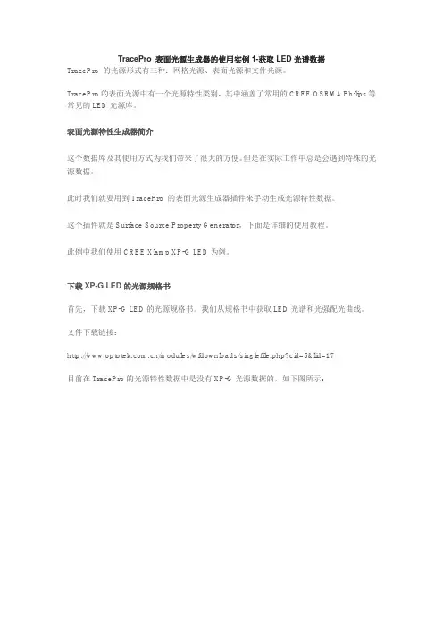
TracePro 表面光源生成器的使用实例1-获取LED光谱数据TracePro 的光源形式有三种:网格光源、表面光源和文件光源。
TracePro的表面光源中有一个光源特性类别,其中涵盖了常用的CREE OSRMA Philips等常见的LED光源库。
表面光源特性生成器简介这个数据库及其使用方式为我们带来了很大的方便。
但是在实际工作中总是会遇到特殊的光源数据。
此时我们就要用到TracePro 的表面光源生成器插件来手动生成光源特性数据。
这个插件就是Surface Source Property Generator,下面是详细的使用教程。
此例中我们使用CREE Xlamp XP-G LED为例。
下载XP-G LED的光源规格书首先,下载XP-G LED的光源规格书。
我们从规格书中获取LED光谱和光强配光曲线。
文件下载链接:/modules/wfdownloads/singlefile.php?cid=5&lid=17目前在TracePro的光源特性数据中是没有XP-G光源数据的,如下图所示:因此需要借助表面光源生成插件来将XP-G的光源数据加入到TracePro的光源特性文件中。
打开Surface Source Property Generator插件打开Surface Source Property Generator插件。
插件整体界面。
首先,我们需要获取LED的光谱特性数据。
针对XP-G型号的光源,我们以5000K~8300K 为例。
光谱曲线导入方法从规格书中获取蓝色曲线为其光谱图。
将此图片复制并粘贴到插件的波长编辑器中。
点击波长编辑器右下角的helper按钮展开光谱图形识别窗口。
光谱曲线定位开始进行光谱数据识别前,需要定义两个坐标点,即矩形窗口的左下角及右上角所代表的数据点。
点击Set Ref 1,然后点击矩形窗口左下角即可看到一个蓝色的圈,此点代表波长为400nm 相对强度为0。
将第二坐标修改为对应0.75 和1。

毕业论⽂:基于tracepro的led导光管设计毕业论⽂:基于Tracepro的LED导光管设计摘要:微细侧发光导光管可以将LED点光源转化成线光源。
为了同时发挥LED光源和CCFL光源的优势,本⽂对导光管模型进⾏了改进,使不同长度导光管均能满⾜良好的出光性能。
在⽹点公式基础上引⼊⾮线性修正参数α,并找到导光管长度与α的对应关系,得到不同长度导光管的优化⽹点排布形式。
针对较短导光管光能利⽤率偏低的问题,采⽤导光管⼀端⼊光,另⼀端镀反射膜的⽅法,可显著提⾼光能利⽤率。
模拟结果表明,该类导光管光能利⽤率达到63%以上,亮度均匀性达到93%以上,可应⽤于⼤中型尺⼨的液晶背光模组中。
TracePro是⼀套普遍⽤于照明系统、光学分析、辐射度分析及光度分析的光线模拟软件。
⽐起传统的原形⽅法,TracePro在建⽴显⽰系统的原型时,在时间上和成本上要降低30-50%。
关键词:LED;导光管;光能利⽤率;TraceProAbstractMicro-opticalside-emitting light pipe can transform LED light from point source to linear source and it has the advantages of both LED and CCFL when used in LCD backlight module. In order to achieve good performance of light pipes with different lengths, this article, improves the light pipe model and introduces nonlinear correcting paramet - 12 -结束语 - 19 -致谢- 20 -参考⽂献 - 21 -第⼀章绪论1.1课题的研究背景及现实意义半导体技术是⼀种健康、节能、环保型照明产品。
TraceProLambda Research Corporation TraceProTracePro/name05TraceProTraceProTraceProTracePro3.01LED23LightPipe TutorialLEDLED TutorialTracePro LC TacePro TracePro ExpertLEDLED LWT676LEDTraceProCrate a Thin Sheet1TracePro File New2View Profiles XY XY3Insert Primative Solid Thin Sheet4mm Insert5Zoom All View Zoom AllSelecting a SurfaceTracePro1Insert Primitive Solid2View Profiles YZ YZ3Edit Select Surface()()-Use Sweep to form a solid4Edit Surface Sweep1Edit Surface Sweep20.9mm43Apply Z(User Sweep DirectionZ Z Z=1)Complete the Solid1Surface420.2mm draft=03Surface840.9mm draft=-4Creat a conical holeLED Cone ReflectorCone(Boolean Subtract operation)1Insert Primitive Solid Cylinder cone2InsertSubtract the Cone from the packageBoolean Operations Body ToolsPackage Cone2System Tree Ctrl2Ctrl3Edit Boolean Subtract42System TreeAdd diffuserdiffuser package thin cylinder diffuser scatteringperfect mirror1Insert Primitive Solid, Cylinder/Cone23Insert CylinderLEDLED Data Sheet0.4×0.4×0.5mm1Insert Primitive Solid Block23LED Z 1.175Block4Insert5System Tree Objects IdentifierDiffusing Surface PropertyLED Diffuser(a perfectLambertian Transmitter)(Conical hole)(perfect reflector)LED(perfect reflective diffuser)Manufactuer1TracePro(Perfect Mirror SurfaceProperty)(diffuser property)2Difine Edit Property Data Surface Properties3Add Property Lambertian DiffuserScatter Model ABg40.0( a lossless surface)(Solve for)BEDF BTDF(Bidirectional Trasmission DistributionFunction )(Surface property)(three foefficients)(Scattering Portion)(ABgmanual)5File Save Property databaseApply diffuser surface property1Define Apply Properties Surface2Diffuser inner surfaceSystem TreeEdit Select Surface Surface3(Zoom)4(Lambertian Diffuser)5ApplyApply Mirror Surface PropertyConical hole base side Mirror Surface1Bottom Ctrl2Property Name Perfect Mirror3ApplyLED Source1Analysis Raytrace Oprions(Raytrace Option)2Option Radiometric Units Photometric3Apply4LED top surface5Apply Properties Surface Source6Source Type Flux7Apply0.05lm LEDPerform the Raytrace1Analysis Source Raytrace Trace RaysTracePro AuditAnalysis Source RaytraceDisplay Candela PlotCandela Plots1Analysis Candela Options2Orientation and Rays3Nomal Vector Up Vector,4Candela Distributions5ApplyTracePro Candela1Analysis Candela Plots Polar Candela Distribution Polar Candela Distribution2LCD Back Lighting TutorialTracePro ExpertTracePro LCD····RepTile()··IrradianceLCDLCD1TracePro;2Insert Primitive Solid3Block X=100Y=10Z=1004Insert5Zoom All()View Zoom AllOpening the System TreeTracePro1Window Split23D3Object SurfaceLCD Adding Material Properties to the LCD PanelTracePro model objects surface LCDMaterial Property Optical1block System Tree Viewing area2tree pop-up menu PropertyApply Properties(TracePro Define Apply Properties)3Material4Plastic Ploycarb56block Plastic PolycarbLCD Adding Surface Properties to the LCD PanelBottom3side12351Object+block object21System tree Viewing area3Ctrl23545Perfect Mirror6Apply7System TreeCreating the Fluorescent Tube1Insert Primitive Solid Cylinder/Cone2Radius length Base Position Base Rotation3Insert CylinderAdding a Surface Property to the Bulb1object+Tree Cylinder32Surface 0System Tree Viewing Screen3Surface 0+Viewing area4Properties5Surface6Fluor White7Apply Properties Apply8Surface 0Surface Property : Fluor WhiteBulbAdding a Surface Source Property to the BulbSurface Source TracePro emittingSurface1Apply Properties Surface Source2Source Type Flux 30WattsTotal Rays 1000Angular Distribution Lambertian3Apply Surface 0Creating the Reflector around the Surfacereflecting surface1Insert Primitive Solid Insert Primitive Solid2Cylinder/Cone3Cylindical Shell4Outside Reflector Dimensions Inside Reflector DimensionsCreating the ReflectorBoolean Subtraction the outer cylinder the inner cylinder1System Tree()2Ctrl System Tree()Ctrl+(Click)3Boolean Subtract icon Edit Boolean Subtract4System Tree65Undo()Edit UndoBlock1Insert Primitive block2sheel3Ctrl+click45half-cylinder reflectorApplying a Surface Property to the Reflector1System Tree Cone 4.9 millimeters(4.9mm)2Apply Properties Surface Diffuse White3Apply4System TreeDiffuse WhiteRepTileCreating a dot pattern using RepTileTracePro Expert Edition RepTile feature1(Define Edit Property Data RepTile Properties)The RepTile Property EditorTracePro Property Editor(TracePro )LCDRepTile Property1RepTile Property EditorAdd RepTile Property2LCD(LCD panel dot pattern for the name)Geometry Type= Sphere3OKSphere Ellipsoid Hip (Mansard) Roof()Cube Corner Prism Rounded Prism/1Tile Parameters Rectangles253Spreadsheet114Bump5Property6Save icon(FileSave)LCD1LCDRepTileSystem Tree2Define Apply PropertiesRepTile3()Diffuse White4Up Vector5Apply98×98mm()SubstratePerfect MirrorholesDiffuse White1mm 5mmDisplay the RepTile SurfaceTracePro RepTile1View Display RepTile()2View Profile()ISO 1Adding an observation ScreenLCD light GuideIrradiance distribution1Insert Primitive Solid Block2Width Position3Observation Screen4Perfect Absorber Surface Property5Turning the Display of Rays off100010001Analysis Display Rays()2Display Rays Check markRunning a source trace simulation1Source TraceSurface Source ray-trace2TracePro Preprocessed34audit TracePro 1000Display Ray TracemodelTraceProRay Sorting1Analysis Ray Sorting2Starting Rays1005update501003AnalysisDisplay RaysDisplay Rays60%100%33%66%0%30%/Displaying an Irradiance MapTraceProAnalysis ModeSimulation Mode/Irradiance/Illuminance maps/Candela/Intensity plots1Analysis Irradiance Options2Irradiance /Irradiance Map3Apply/Irradiance map12Irradiance map(Analysis Irradiance/Illuminance map/)34Irradiance map5WindowTile Vertical Tile VerticalImprove Irradiance Sampling1000Irradiance plot1Analysis Display Rays2Source Surface100010000Adding a Surface Source Property to theBulb3Irradiance MapUnderstanding the Irradiance Options/Irradiance/Illuminance Options Analysis MenuIrradiance/Illuminance mapRays to plot Absorbed irradiance/illuminanceincident Irradiance/Illuminance MapWatts WattsAnalysis Raytrace Options Radiometric Units radiometric unitsPhotometric UnitsNormalize to emitted box irradiance mapforeground backgroundcolor mapBlack&White andgrayscale mapsCountnumber of pixels20detector2020larger countsViewSmoothing Gaussiansmoothing detector pixelsChoppy or non-contiguous datadebuggingGaussian smoothingfunctionLightPipe TutorialTracePro LC TracePro TracePro ExpertTraceProTracePro1TracePro File View2Insert Primative Solid Cylinder/Cone3230Insert4Zoom All View Zoom AllSelecting a SurfaceTracePro1Edit Select Surface(Select Surface tool)rod right endSystem Tree Window Split System TreeAdding a Bendarc1Edit Surface Revolve()Revolve Surface Selection290253Swept revolved(0,-25,30)X4Revolve SurfaceAdd a tapertaper1Edit Surface Sweep Sweep Surface Selection2Distance15Draft angle -22Apply a Material PropertyTracePro Properties make the mode optical bulk V olumethe index of refraction1Edit Select Object(Select Object)2Define Apply Properties()Apply Properties3Plastic Catalog Acrylic Apply System Tree ObjectMaterial Property NameSetup a Grid of RaysGrid RaytraceGaussian beam1Define Grid Source()Grid Source2Grid Setup Outer radius2Grid Pattern RandomTotal rays1000(0,0-0.1)3Beam Setup()Gaussian (degrees)()Angular profile30Half anglesTrace the RaysGrid RaytraceApply & Trace Rays(&)TraceProAudit Audit database Property informationAnalysis Display RaysAnalysis Ray Sorting()/Setting Irradiance Map OptionsIrradiance Map Options Irradiance Plot1AnalysisIrradiance/Illuminance OptionsApply/Display the Irradiance Plot1AnalysisIrradiance/Illuminance Maps Irradiance MapIrradiance Map2Normalized FluxSurface 4Candela OptionsCandela Options Candela Plots1Analysis Candela Options ApplyIso-Candela Ploar Iso-Candela PlotTracePro Missed Rays1Analysis Candela Plots Polar Iso-Candela Polar Iso-Candela2CandelaTraceProSystem TreeModel WindowZoom AllPrimative solidCylinder/Cone /Polar Candela DistributionDraft angleEdit Property DataSurface PropertiesRepTileIrradianceLensApertureSemi-DiameterSemi-diameterDecenterObstructionPositionAsphericunitsthinknesscatalogcylindricPrimitive SolidsBlockCylinder/cone /TorusSphereThin SheetplaneDefineApply PropertiesEdit Property DataSurface PropertiesMaterial PropertiesBulk Scatter PropertiesGradient Index PropertiesRepTile PropertiesFluorescence PropertiesThin film StacksMaterialSurfaceSurface SourceI, IntensityF FluxE IlluminanceirradiancePrescriptionImportance SamplingExit surfaceRaytrace FlagDiffractionMueller MatrixBluk ScatteringClass and User DataTemperatureTemperature DistributionGradient IndexDisplay of Index and absorptance for given wavelengthMirrorPerfect AbsorberProperty/Irradiance/Illuminance MapBoolean Subtract OperationRevolveSweepZoom AllRay SortingIR。