melotalk万年历说明书
- 格式:docx
- 大小:12.56 KB
- 文档页数:1
一、实训目的与要求:(1)、学会基本电子元器件的识别,熟悉一些常用电子器件的功能与作用。
(2)、掌握液晶显示电子万年历的组成和工作原理,学会分析基本的电路原理图。
(3)、学会利用电路原理图检查、处理电路故障、调试。
二、实训内容:(1)、掌握电烙铁的正确使用方法和基本的焊接技术,学会识别不同的元器件及其安装方法。
(2)、掌握液晶显示电子万年历的工作原理,学会识别电路原理图与印刷图、电容、电阻的识别与测试,进一步掌握和熟练焊接技术。
(3)、测试各元件的好坏,安装元件到电路板上,焊接断电并测试。
整机调试与验收。
三、软件和硬件设计:3、1 软件调试平台Keil for C51是美国Keil Software公司出品的C语言软件开发系统,与汇编相比,C语言在功能上、结构性、可读性、可维护性上有明显的优势,Keil C51软件还提供了丰富的库函数和功能强大的集成开发调试工具,生成的目标代码效率非常高,且容易理解。
C51开发中除了必要的硬件外,同样离不开软件,我们写的源程序要变为C51可以执行的机器码有两种方法,一种是手工汇编,另一种是机器汇编,但现在已极少使用手工汇编。
Keil提供了包括C编译器、宏汇编、连接线、库管理和一个功能强大的仿真调试器等在内的完整开发方案,通过一个集成开发环境(uVision2)将这些部分组合在一起。
如图下图所示。
3、2 系统软件程序(1)LCD1602液晶显示程序#include<reg51.h>sbit rs=P1^2;sbit rw=P1^1;sbit en=P1^0;sbit s1=P3^4;sbit s2=P3^5;sbit s3=P3^6;char miao,shi,fen;unsigned char code tab[]=" 2012-10-19 MON";unsigned char code tab1[]=" 00:00:00";void delay(unsigned int z){unsigned int x,y;for(x=z;x>0;x--)for(y=0;y<150;y++);}void write_com(unsigned char cmd){rs=0;rw=0;en=1;P2=cmd;en=0;delay(2);//当不检测忙标志信号时,每次至少需要2ms }void write_data(unsigned char dat){rs=1;rw=0;en=1;P2=dat;en=0;delay(2);//当不检测忙标志信号时,每次至少需要2ms }void init(){unsigned char num;write_com(0x38);write_com(0x08);write_com(0x01);write_com(0x0f);write_com(0x06);write_com(0x80);for(num=0;num<16;num++){write_data(tab[num]);}write_com(0x80+0x42);for(num=0;num<13;num++){write_data(tab1[num]);}TMOD=0X01;TH0=(65535-50000)/256;TL0=(65535-50000)%256;EA=1;ET0=1;TR0=1;}void main(){init();while(1);}3、3 系统硬件设计(1)LCD1602液晶显示四、LCD1602介绍:4、1 LCD1602引脚功能4、2 LCD1602硬件应用图4、3 LCD1602操作时序4、5 LCD1602内部RAM地址4、6LCD1602读/写操作时序图五、电子万年历功能状态说明:5、1 整点闹铃设置在正常时间状态下,按住“UP”键2秒以上将切换整点闹铃的关与开;注意低于2秒将显示年份。
万年历时钟蓝牙语音芯片KT1025A使用说明一、简介传统的万年历产品,基本都是靠按键的方式去设置时间。
如果在生产阶段也是工人一个一个的手工校准,效率非常的地下。
这里我们推荐使用蓝牙更新时间,批量的时候使用U盘更新时间或者设置方法KT1025A支持非常多的功能,蓝牙双模BLE和SPP数据透传,支持读写U盘或者TF卡里面的txt文件,支持用户自己录音。
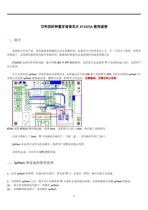
芯片支持外挂spiflash,用来存储音乐或者语音。
支持通过芯片的USB端口直接拷贝MP3文件至外挂的spiflash中,实现方式是将spiflash虚拟成U盘,像拷贝U盘一样拷贝文件进去。
无需驱动,无需任何上位机。
BT301或者BT321F模块测试板,需要flash,这需要自己焊上flash,然后贴上电阻即可。
注意只要贴上了flash,TF卡功能就不能用了。
只能二选一。
因为他们共用了IO口Spiflash在这里可以作为语音报时,或者用户设置语音提示等等支持的U盘,可以作为MP3播放设备二、Spiflash和设备的使用说明1、这里spiflash的管理,在我们的方案中,其实和TF卡、U盘是一样的,都可以称之为设备。
2、当切换至spiflash之后,那么芯片会释放掉TF卡或者U盘的驱动资源,全部资源就去加载spiflash的驱动(1)、如文件系统的读写接口,切换至spiflash(2)、音频解码的读接口,也切换至spiflash。
3、所以都可以串口AT指令去控制,比如:下一曲、上一曲、播放暂停、按照物理序号指定播放等等。
和TF卡以及U 盘的操作方式是一模一样4、如果需要使用spiflash,需要指定模式为spiflash即可,看看手册的CM指令5、切换至flash之后,就可以正常操作了。
注意,一定是要支持spiflash的版本才可以。
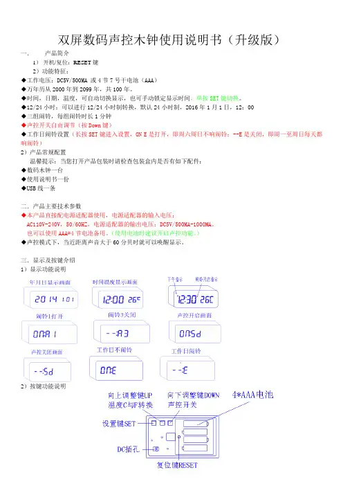
双屏数码声控木钟使用说明书(升级版)一.产品简介1)开机/复位:RESET键2)功能特征:◆工作电压:DC5V/500MA 或4节7号干电池(AAA)◆万年历从2000年到2099年,共100年。
◆时间,日期,温度,可自动切换显示,也可手动锁定显示时间,单按SET键切换。
◆12/24小时:可以进行12/24小时制转换,默认24小时制,2016年1月1日,12:00◆三组闹铃,每组闹铃时长1分钟◆声控开关自由调节(按Down键)◆工作日闹铃设置(长按SET键进入设置,ON E是打开,即周六周日不响闹铃;--E是关闭,即周一至周日每天都响闹铃)2)产品常规配置温馨提示:当您打开产品包装时请检查包装盒内是否有如下配件:◆数码木钟一台◆使用说明书一份◆USB线一条二.产品主要技术参数◆本产品直接配电源适配器使用,电源适配器的输入电压:AC110V-240V,50/60HZ,电源适配器的输出电压:DC5V/500MA-1000MA。
也可以使用AAA*4节电池备用。
(使用电池时建议开启声控功能。
)◆声控模式下,当近距离声音大于60分贝时就可以唤醒显示。
三.显示及按键介绍1)显示功能说明2)按键功能说明四.功能设置在正常显示状态下,长按设置键(SET),3秒不放,显示闪动。
设置顺序为:年-月-日→12H/24H→时-分→闹钟(A1-时-分,A2-时-分,A3-时-分)→工作日闹铃开关。
◆年设置:按住设置健(SET)三秒,年所在位闪动,按向上键(UP)/向下键(DOWN)可以向上或向下调整,长按可以快进/快退◆月设置:年设置完成后,再按设置健(SET)进入月调整,月所在位闪动,按向上键(UP)/向下键(DOWN)可以向上或向下调整,长按可以快进/快退◆日设置:月设置完成后,再按设置健(SET)进入日调整,日所在位闪动,按向上键(UP)/向下键(DOWN)可以向上或向下调整,长按可以快进/快退◆12/24H设置:日设置完成后,再按设置健(SET)进入12/24小时调整,按向上键(UP)/向下键(DOWN)可切换12/24小时制。
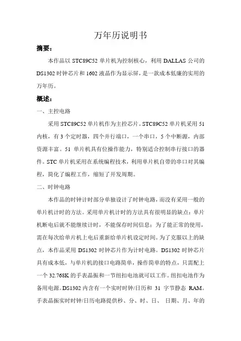
万年历说明书摘要:本作品以STC89C52单片机为控制核心,利用DALLAS公司的DS1302时钟芯片和1602液晶作为显示屏,是一款成本低廉的实用的万年历。
概述:一、主控电路采用STC89C52单片机作为主控芯片。
STC89C52单片机采用51内核,有3个定时器,四个并行端口,一个串口,5个中断源,内部资源丰富。
51单片机具有位操作能力,特别适合控制串行接口的器件。
STC单片机采用在系统编程技术,利用单片机自带的串口对其编程,简化了编程工作,缩短了开发周期。
二、时钟电路本作品的时钟计时部分单独设计了时钟电路,而没有采用一般的单片机计时的方法。
采用单片机计时的方法具有很明显的缺点:单片机断电后就不能继续计时,不能保存时间信息;为了能正常的使用,需在每次给单片机上电后重新给单片机设定时间。
为了克服以上的缺点,本作品采用DS1302时钟芯片作为计时电路。
DS1302时钟芯片具有成本低,与单片机的接口电路简单,操作简单的特点,只需配上一个32.768K的手表晶振和一节纽扣电池就可以工作。
纽扣电池作为备用电源。
DS1302内含有一个实时时钟/日历和31 字节静态RAM。
手表晶振实时时钟/日历电路提供秒、分、时、日、日期、月、年的信息,每月的天数和闰年的天数可自动调整,时钟操作可通过AM/PM 指示决定采用24或12小时格式。
三、显示显示部分采用1602 液晶,具有美观,显示的信息量大,操作方便的特点。
1602液晶内带英文字库和各种图形符号,大大的简化了编程工作。
四、电源本作品采用USB供电,USB电压是标准的5V电压,手机充电器,MP3充电器等都能够提供,省去了电池供电所必须的稳压电路,使电路简化。
作品原理图:部分程序代码:#include<reg52.h>#include"1602.h"#include"DS1302.h"sbit LED = P2^0;/***********主函数**************/void main(void){SYSTEMTIME CurrentTime;unsigned char Second;LCD_init();delay_nms(100)DS1302_Initial();LCD_dsp_string(0,1,"Date: ");LCD_dsp_string(0,2,"Time: ");//LCD_dsp_string(1,1,"LCDTEST");//在第一行第一列显示"LCDTEST"//LCD_dsp_string(1,2,"SUCCESSFUL");//在第二行第一列显示"SUCCESSFUL"CurrentTime.Year = 9;CurrentTime.Month = 10;CurrentTime.Day = 21;CurrentTime.Week = 3;CurrentTime.Hour = 10;CurrentTime.Minute = 28;CurrentTime.Second = 27;DS1302_SetTime(&CurrentTime);while(1){DS1302_GetTime(&CurrentTime);if(Second!=CurrentTime.Second) {Second=CurrentTime.Second;LED = ~LED;}LCD_dsp_string(6,1,"20");LCD_dsp_char(8,1,(CurrentTime.Year%100)/10+0x30);LCD_dsp_char(9,1,(CurrentTime.Year%10)+0x30);LCD_dsp_string(10,1,"-");LCD_dsp_char(11,1,(CurrentTime.Month/10)+0x30);LCD_dsp_char(12,1,(CurrentTime.Month%10)+0x30);LCD_dsp_string(13,1,"-");LCD_dsp_char(14,1,(CurrentTime.Day/10)+0x30);LCD_dsp_char(15,1,(CurrentTime.Day%10)+0x30);LCD_dsp_char(6,2,(CurrentTime.Week)+0x30);LCD_dsp_char(8,2,(CurrentTime.Hour%100)/10+0x30);LCD_dsp_char(9,2,(CurrentTime.Hour%10)+0x30);LCD_dsp_string(10,2,":");LCD_dsp_char(11,2,(CurrentTime.Minute/10)+0x30);LCD_dsp_char(12,2,(CurrentTime.Minute%10)+0x30);LCD_dsp_string(13,2,":");LCD_dsp_char(14,2,(CurrentTime.Second/10)+0x30);LCD_dsp_char(15,2,(CurrentTime.Second%10)+0x30);}}。
河北工程大学科信学院课程设计说明书(2012 /2013 学年第 1 学期)课程名称:小型数字系统设计1题目:电子钟专业班级:计算机1021班****:***学号:*********指导教师:赵建明蔡恒设计周数: 1 周设计成绩:二〇一三年一月十八日一、选题意义电子钟是对时、分、秒等用数字显示的计时装置,广泛用于个人家庭、车站、办公室等公共场所,成为人们日常生活中不可少的必需品。
钟表的数字化给人们生产生活带来了极大的方便,而且大大地扩展了钟表原先的报时功能。
诸如定时自动报警、按时自动打铃、时间程序自动控制、定时广播、自动起闭电路、甚至各种定时电器的自动启用等,所有这些,都是以钟表数字化为基础的。
因此,研究数字电子钟及扩大其应用,有着非常现实的意义。
二、项目设计方案2.1 硬件选取与说明2.1.1硬件选择及数量AT89C51 单片机1个、 7SEG-MPX1-CC (1位七段数码管)1个、7SEG-MPX2-CC(1位七段数码管)5个、7SEG-MPX4-CC(1位七段数码管)1个、NPN三极管一个、蜂鸣器一个、七段显示译码器7448与74141 BCD—十进制译码器/驱动器各两片。
2.1.2 单片机端口设定单片机端口选择:根据选用的AT89C51单片机将P0口的低4位作为时间数据显示的数据输出端口,高4位作为数码管选择端口。
P1端口的低4位作为日期的数据输出端口,高4位作为日期显示数码管的选择端口。
P2.6端口作为蜂鸣器控制端口,INT0、INT1两中断引脚作为更改数据的按键。
2.1.3 方案设计(1) 方案设计框图见图1图1方案设计框图(2)电路原理图图2电路原理图2.2软件设计2.2.1 系统分析电子钟包含时间、日期、星期的显示。
其中时间包含有秒与分、分与小时之间的逻辑;日期中包含日于月、月与年、星期计算等逻辑;时间与日期之间也存在逻辑。
具体逻辑如下:(1)其中秒最大计数不能超过60,超过60后应置0重新计数。

P m o d R T C C ™ R e f e r e n c e M a n u a lRevision: October 17, 2011Note: This document applies to REV A of the board.1300 NE Henley Court, Suite 3Pullman, WA 99163(509) 334 6306 Voice | (509) 334 6300 FaxDoc: 502-218page 1 of 2OverviewThe PmodRTCC is a real-time clock/calendar powered by the Microchip MCP79410.Features include:• a real-time clock/calendar with lithiumcoin cell back-up • an I 2C interface• multi-function pin output that cangenerate a square wave • two available alarms • 128 bytes EEPROM • 64 bytes SRAMFunctional DescriptionThe PmodRTCC can communicate using I 2C via the 8-pin header J2. Digilent boardsimplement several different I 2C interfaces. For more information, see the Connecting I 2C Interfaces document available at .InterfaceAll communications with the device mustspecify whether to write to the EEPROM or the RTCC registers/SRAM, as well as a register address and a flag indicating whether the communication is a read or a write. This is followed by the actual data transfer.The PmodRTCC responds to two I 2C addresses. Address ‘1010111’ is used for access to the EEPROM, and address ‘1101111’ is used for access to RTCC registers/SRAM.The device is configured by writing to the registers within the device. The time registers can be set to specific values and a control register sets their functionality.A full list of registers and their functionality, as well as communication specifications, can be found in the MCP79410 datasheet available at the Microchip website.The I 2C interface standard uses two signal lines. These are I2C data (SDA) and serial clock (SCLK). These signals map to the serial data (SDA) and serial clock (SCLK) on the MCP79410.Power Back-upThe PmodRTCC has a holder for a 12mmlithium coin cell to power the RTCC and SRAM if VDD should ever fall below the operating point. In order to enable this power back-up, the VBATEN bit must be set in the RTCC registers. Compatible coin cells includeBR1216, CR1216, BR1220, CL1220, CR1220, and BR1225.Connector J2 – I2C Communications Pin Signal Description 1, 2 SCL I2C Clock 3, 4 SDA I2C Data 5, 6 GND Power Supply Ground 7, 8 VCC Power Supply (3.3V)PmodRTCC Reference Manualpage 2 of 2Multi-Function Pin (MFP)The MFP can be accessed via the 2-pin header J1. The MFP has an open drainoutput. To use it, an external 3.3V 2-10K-ohm pull-up resistor is required.The MFP can have several different functions including user-controllable output, alarmoutput, and clock frequency output, depending on the settings in the RTCC registers. Settings and functions are described in the MFP section of the MCP79410 datasheet.AlarmsThe MCP79410 has two alarms. Each can be set to trigger an alarm interrupt flag at a particular time, driving the MFP high or low depending on how the polarity bit is set.CalibrationThe Calibration register in the MCP79410 can calibrate the device to correct for inaccuracies of the input clock source. It can add or subtract up to 254 clocks from the RTCC counter every minute. For more information, see the Calibration section of the MCP74910 datasheet.Connector J1 – MFP Header Pin Signal Description 1 MFP Multi-Function Pin 2 GND Power Supply Ground。

电子语音播放万年历1.功能描述对日期时间计时、温度测量。
LCD显示年月日、时分秒,温度值。
可设置时间,可将当前时间、温度值语音播放。
2. 产品模块配置①EDM314-±12V,±5V直流电源模块。
②EDM315-变压器。
③EDM001-MCS51主机④EDM605-12864点阵液晶⑤EDM103-温度传感器18B20⑥EDM403-8位独立按键⑦EDM313-AK040语音⑧EDM503-扬声器3. 单元模块电路及功能4.产品模块连线各模块连好5V电源EDM605-12864点阵液晶与EDM001-MCS51连接:DB0-DB7---连---P0.0-P0.7、RST-BL-NC---连---P2.7-P2.0EDM403-8位独立按键:→-F2----连----- EDM001-MCS51:P3.7-P3.0 EDM103-温度传感器18B20:OUT—连—P1.7EDM-313-AK040语音模块与EDM001-MCS51连接:RESET—连—P1.0、PULSE—连—P1.1、BUSY--连—P1.2.EDM-313-AK040语音模块:OUT--连--EDM503-扬声器:SP- EDM503-扬声器:SP+--连5VEDM001-MCS51拨码开关5678拨到ON.5.产品电路总图6.调试方法及步骤连好线开机后,液晶显示亚龙LOGO,大约6秒后进入主界面,此时按“F1”键会播放当前温度, 按“F2”键会播放当前时间和当前温度。
按“SET”键会进入时间设置界面,->和<-移位,↑和↓加1和减一。
OK键保存修改,同时退出。
7.测试点参数。
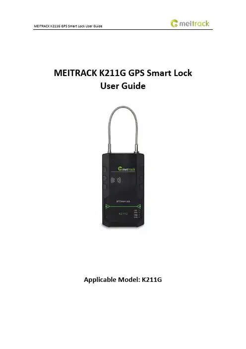
MEITRACK K211G GPS Smart LockUser GuideApplicable Model: K211GChange HistoryContents1 Copyright and Disclaimer........................................................................................................................................... - 4 -2 Product Introduction ................................................................................................................................................. - 4 -2.1 Product Features........................................................................................................................................... - 4 -2.1.1 LoRa Communication (Optional).......................................................................................................... - 4 -2.1.2 Locking or Unlocking the K211G .......................................................................................................... - 5 -2.1.3 Dual SIM Cards..................................................................................................................................... - 6 -2.1.4 Magnetic Charging............................................................................................................................... - 7 -2.1.5 Strong Magnetic Adsorption................................................................................................................ - 7 -2.1.6 Anti-collision Soft Adhesive ................................................................................................................. - 8 -2.1.7 Security Performance - Super Password .............................................................................................. - 8 -3 Product Functions...................................................................................................................................................... - 9 -3.1 Position Tracking........................................................................................................................................... - 9 -3.2 Alerts ............................................................................................................................................................ - 9 -3.3 Other Functions .......................................................................................................................................... - 10 -4 Product Specifications ............................................................................................................................................. - 10 -5 Main Device and Accessories .................................................................................................................................. - 11 -6 First Use................................................................................................................................................................... - 11 -6.1 Installing a SIM Card ................................................................................................................................... - 11 -6.2 Turning on the K211G ................................................................................................................................. - 12 -6.3 LED Indicator............................................................................................................................................... - 13 -6.4 Device Configuration .................................................................................................................................. - 13 -6.4.1 Installing the USB Driver .................................................................................................................... - 13 -6.4.2 Configuring Device Parameters by Meitrack Manager....................................................................... - 14 -6.5 Binding or Unbinding the T399G ................................................................................................................ - 15 -6.5.1 Binding the T399G ............................................................................................................................. - 15 -6.5.2 Unbinding the T399G......................................................................................................................... - 15 -6.6 Common SMS Commands .......................................................................................................................... - 16 -6.6.1 Setting GPRS Parameters – A21 ......................................................................................................... - 16 -6.6.2 Setting a Smart Sleep Mode – A73 .................................................................................................... - 16 -6.6.3 Setting the Maximum Working Time of the Woken GPS Module – A83 ............................................ - 16 -6.6.4 Setting the SMS Time Zone – B35 ...................................................................................................... - 17 -6.6.5 Disabling the Power-off Function of the Power Button – C77 ........................................................... - 17 -6.6.6 Authorizing an RFID Card – D10......................................................................................................... - 17 -6.6.7 Authorizing RFID Cards in Batches – D11........................................................................................... - 17 -6.6.8 Locking or Unlocking the K211G – D82.............................................................................................. - 18 -6.6.9 Selecting a Locking Method – D83..................................................................................................... - 18 -6.6.10 Setting the automatic authorization time of swiping the RFID card – DB0...................................... - 18 -6.6.11 Changing Super Password – F22 ...................................................................................................... - 19 -7 Using the Platform................................................................................................................................................... - 19 -7.1 MS03 Tracking System ................................................................................................................................ - 19 -7.2 Authorizing RFID Cards in Batches by MS03 ............................................................................................... - 19 -8 Device Installation ................................................................................................................................................... - 21 -1 Copyright and DisclaimerCopyright ©2019 MEITRACK. All rights reserved.,andare trademarks that belong to Meitrack Group and its subsidiary.The user manual may be changed without notice.Without prior written consent of Meitrack Group, this user manual, or any part thereof, may not be reproduced for any purpose whatsoever, or transmitted in any form, either electronically or mechanically, including photocopying and recording.Meitrack Group shall not be liable for direct, indirect, special, incidental, or consequential damages (including but not limited to economic losses, personal injuries, and loss of assets and property) caused by the use, inability, or illegality to use the product or documentation.2 Product IntroductionThe K211G is a GPS smart lock that supports Long Range (LoRa) and GPRS communication. Its main functions include real-time lock status monitoring, anti-tamper alert, anti-cut alert, swiping an RFID card to lock or unlock the device, and super long standby time. There is no button on the outer case of the device, and the IP67 water resistance rating makes the device withstand harsh environments ,and the device also has a crash-proof housing design. It is specially designed for door lock management in various land and sea transportation such as box trucks, trailers and containers.2.1 Product Features2.1.1 LoRa Communication (Optional)This function is used for communication between the K211G and the T399G vehicle tracker. After the LoRa connection is successful, the K211G will send information such as lock status information and battery power to the T399G via LoRa. To establish LoRa communication between the K211G and the T399G, the two devices must be bound each other. For details about how to bind the T399G to the K211G, see the section 6.5 "Binding or Unbinding the T399G."LoRa connection process:T399G and K211G communication features:Communication diagram2.1.2Locking or Unlocking the K211G Locking or Unlocking by Swiping RFID CardsThe function is used to lock or unlock the K211G by swiping authorized RFID cards. When you swipe an RFID card, the K211G will automatically detect and record the unlocking time, location and RFID card number, and these data will be sent to the server.Operation process: Put the authorized RFID card on the K211G's card swiping area. When the K211G detects this action, the buzzer will beep and the LVS LED indicator will be steady on, indicating that the K211G is unlocked. In this way, the last step for you is to pull out the lock rope. (To lock the K211G, you only need to swipe the RFID card once. Then the buzzer will beep and the LVS LED indicator will be off, indicating that the K211G is locked.)Swiping an RFID card:Note: In the locking or unlocking state, if you swipe an unauthorized RFID card, the buzzer will beep twice,but the K211G cannot be unlocked and locked. If you swipe an authorized RFID card, the buzzer will beep once. Before the K211G is locked,it is recommended to apply appropriate force on the lock rope first to make the waterproof ring of cable fully contact with the lock hole and improve the waterproof performance,and if the lock rope is cut, K211G cannot be locked. After the K211G is unlocked, if you do not pull out the lock rope within one minute, the K211G will be locked automatically.2.1.3Dual SIM CardsThe K211G can be installed with two Micro SIM cards and supports the dual SIM single standby mode. The device will automatically select a SIM card to register the network. SIM1 (on the right) will be selected by default. If SIM1 fails to register the network, SIM2 (on the left) will be selected to do this. (Please ensure that at least one SIM card can be used normally.)2.1.4Magnetic ChargingYou can use the magnetic charging cable to charge the K211G. The device supports 9V/2A power adapter, and it will take a total of 7.5–8 hours to charge the device fully.2.1.5Strong Magnetic AdsorptionThe back of the cover plate has strong magnetic, which can be adsorbed to the car door to prevent the device from shaking during movement.2.1.6Anti-collision Soft AdhesiveThe gray protruding part in the figure is Anti-collision soft adhesive, which has shock absorption effect and it can effectively protect the device from being damaged in the collision.2.1.7Security Performance - Super PasswordTo enhance security, K211G supports super password.Super password (the default is 666888) supports all SMS commands, but DB0 / D82 / D10 / D11 / D14 D15 / A21 / F22 commands can't use the original SMS password (the default is 0000), they can only use super password.When setting GPRS parameters through Meitrack Manager, you need to open the super password first before setting successfully:Note:It is recommended to set a new super password first, because the super password is related to the security of unlocking; The default super password is 666888, which can be modified by Meitrack Manager and F22 command.Please make sure to remember the super password, and the super password cannot be quested and reset to the original value, once you forget the password, it will not be able to recover.3Product Functions3.1Position Tracking●GPS + LBS positioning●Real-time location query●Tracking by time interval●Tracking by distance●Tracking by mobile phone●Speeding alert●Cornering report●Geo-fence3.2Alerts3.3Other Functions4Product Specifications5 Main Device and AccessoriesNote: Two RFID cards are standard, optional more and white type RFID card. The Power adapter(9V) can choose UL or VDE.6 First Use6.1 Installing a SIM CardRemove the four screws from the cover and take the cover out.GPS smart lock with the batteryLock rope (30 cm)RFID cardPower adapter(9V)Magnetic USB charging cableUSB cable CD download cardInsert a SIM card into one of the card slots (SIM1: right; SIM2: left).6.2Turning on the K211GPress the power button for 3 seconds. Then the GPS and GSM LED indicators will blink fast, indicating that the device is turned on.Note: When using the device for the first time, you are advised to charge the battery fully.6.3LED Indicator6.4Device Configuration6.4.1Installing the USB DriverInstall the USB driver on a computer with 64-bit Windows system.After the installation is finished, connect the K211G to the computer by USB cable. If Prolific USB-to-Serial Comm Port (COM3) is displayed on the Device Manager page, the driver is installed successfully.Note: Before connecting the K211G to the computer by USB cable, turn on the K211G first. Otherwise, it cannot be detected by Meitrack Manager.6.4.2Configuring Device Parameters by Meitrack ManagerThis section describes how to use Meitrack Manager to configure the K211G on a computer.Operation steps:1.Install the USB driver and Meitrack Manager.2.Connect the device to a computer by using the USB cable.3.Run Meitrack Manager (6.0.0.9 version or later), then the following dialog box will appear:4.Turn on the device, then Meitrack Manager will automatically detect the device model and the parameter pagewill appear accordingly.For details about Meitrack Manager, see the MEITRACK Manager User Guide.6.5Binding or Unbinding the T399G6.5.1Binding the T399GTo make the K211G and T399G communicate with each other via LoRa, bind the two devices. An IMEI number is the default binding information.Perform the following steps to bind the T399G:1.Go to the Peripheral page of Meitrack Manager.2.Enter the IMEI number of the T399G.3.Click Binding.4.Click Set.After the binding is successful, the IMEI number of the T399G will displayed on the GPS Smart Lock Information area.Note: To establish LoRa communication between the K211G and the T399G, the two devices must be bound each other. Please connect the T399G to the computer, and then repeat the above operations to bind the K211G.6.5.2Unbinding the T399GThis operation is used to disconnect the communication between the K211G and the T399G. After the unbinding is successful, the GPS positioning and GSM communication functions of the K211G will be enabled automatically. Lock status information will be uploaded to the server through the K211G.Perform the following steps to unbind the T399G:1.Go to the Peripheral page of Meitrack Manager.2.Select the IMEI number to be unbound.3.Click Unbind.4.Click Set.Note: The binding and unbinding functions are only available for the K211G with a LoRa module.6.6Common SMS Commands6.6.1Setting GPRS Parameters – A216.6.2Setting a Smart Sleep Mode – A736.6.3Setting the Maximum Working Time of the Woken GPS Module – A836.6.4Setting the SMS Time Zone – B356.6.5Disabling the Power-off Function of the Power Button – C776.6.6Authorizing an RFID Card – D106.6.7Authorizing RFID Cards in Batches – D116.6.8Locking or Unlocking the K211G – D826.6.9Selecting a Locking Method – D836.6.10Setting the automatic authorization time of swiping the RFID card – DB06.6.11Changing Super Password – F22Note: For details about SMS commands, see the MEITRACK SMS Protocol.7Using the Platform7.1MS03 Tracking SystemVisit , enter the user name and password, and log in to the MS03. (Purchase the login account from your provider.)For more information about how to add a device, see the MEITRACK GPS Tracking System MS03 User Guide (chapter 4 "Getting Started").The MS03 supports the following functions:●Track by time interval or distance.●Query historical trips.●Set polygonal geo-fences.●Bind driver and vehicle information.●View various reports.●Send commands in batches.●Support OTA updates.For details, see the MEITRACK GPS Tracking System MS03 User Guide.7.2Authorizing RFID Cards in Batches by MS031. On the main interface of the MS03, choose Management.2. On the Management window that is displayed, select Sending command from Use Normal.3. On the Sending command window that is displayed, set Command to Authorize RFID cards in batches, enter the RFID card start number and the number of cards, and click Send command.If only one RFID card needs to be authorized, the number of cards is 1. After the RFID cards are authorized successfully, you can swipe these cards to unlock and lock the K211G and record operator information.8Device InstallationIfyouhaveanyquestions,*****************************************.Copyright © 2019 Meitrack Group All rights reserved. - 21 -。
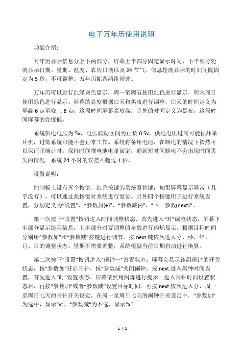
电子万年历使用说明功能介绍:万年历显示信息分上下两部分,屏幕上半部分固定显示时间,下半部分轮流显示日期、星期、温度、农历日期以及24节气。
信息轮流显示的时间间隔固定为5秒,不可调整。
万年历配备两组闹钟。
万年历可以进行红绿双色显示,周一至周五使用红色进行显示,周六周日使用绿色进行显示。
屏幕的亮度根据白天和黑夜进行调整,白天的时间定义为早晨6点至晚上8点,这段时间屏幕亮度高;另外的时间定义为黑夜,这段时间屏幕的亮度低。
系统供电电压为5v,电压波动区间为正负0.5v,供电电压过高可能损坏单片机,过低系统可能不会正常工作。
系统有备用电池,在断电的情况下依然可以保证正确计时,保持时间视电池电量而定,通常短时间断电不会出现时间丢失的情况。
系统24小时的误差不超过1秒。
设置说明:控制板上设有五个按键,红色按键为系统复位键,如果屏幕显示异常(几乎没有),可以通过此按键对系统进行复位。
另外四个按键用于进行系统设置,分别定义为“设置”、“参数加(+)”、“参数减(-)”、“下一参数(next)”。
第一次按下“设置”按钮进入时间调整状态。
首先进入“时”调整状态,屏幕下半部分显示提示信息,上半部分对要调整的参数进行闪烁显示。
根据目标时间分别用“参数加”和“参数减”按键进行调节。
按next键依次进入分、秒、年、月、日的调整状态。
星期不需要调整,系统根据当前日期自动进行换算。
第二次按下“设置”按钮进入“闹钟一”设置状态。
屏幕会显示该组闹钟的开关状态,按“参数加”开启闹钟,按“参数减”关闭闹钟。
按next进入闹钟时间设置,首先进入“时”设置状态,屏幕依然用闪烁进行提示。
进入闹钟时间设置状态后,再按“参数加”或者“参数减”设置目标时间。
再按next依次进入分、周一至周日七天的闹钟开关设定。
在周一至周日七天的闹钟开关设定中,“参数加”为选中,显示“v”,“参数减”为不选,显示“x”。
第三次按下“设置”按钮进入“闹钟二”设置状态。

名士卡普兰系列说明书摘要:一、名士卡普兰系列产品简介1.名士卡普兰品牌背景2.系列产品种类及特点二、产品使用说明1.使用前的准备工作2.产品使用步骤及注意事项3.常见问题及解决方法三、产品维护与保养1.日常清洁与维护2.定期检查与保养3.配件更换与升级四、售后服务与保障1.售后服务政策2.维修与换货流程3.客户反馈与建议正文:名士卡普兰系列产品是知名品牌,凭借其精湛的工艺和卓越的品质赢得了广大消费者的青睐。
本系列产品种类丰富,包括高端手表、精美皮具、时尚配饰等,满足不同消费者的需求。
在使用名士卡普兰系列产品前,请确保仔细阅读产品说明书,了解产品功能、操作方法以及注意事项。
在开始使用前,请确保产品电量充足,并按照说明书中的指引进行操作。
此外,使用过程中应避免产品受到撞击、进水等意外情况,以免影响产品性能。
若在使用过程中遇到问题,可以先参考说明书中的常见问题解答。
如仍无法解决,请及时联系售后服务部门,我们将竭诚为您提供帮助。
为了保持名士卡普兰系列产品的性能和使用寿命,日常清洁与维护是必不可少的。
建议定期用柔软的干布擦拭产品表面,避免使用含有酒精或其他化学成分的清洁剂。
同时,请定期检查产品的连接线、按钮等部件,确保其正常运作。
名士卡普兰品牌重视售后服务,我们承诺为消费者提供优质的售后保障。
如产品出现非人为损坏,可享受一年内免费维修、更换服务。
如有任何疑问或建议,欢迎随时联系我们的客服人员,我们将竭诚为您服务。
总之,名士卡普兰系列产品凭借其卓越品质和贴心售后服务,成为消费者心目中的理想之选。

Universal Benchtop Digital Panel MetersSingle Channel Models with Embedded Ethernet Connectivity OptionMDS8PT SeriesU U niversal Inputs U E asy-to-Use and Configure U O ptional Embedded Internet U B uilt Around OMEGA’s New PLATINUM Meter U H igh Quality U 5-Year Warranty U H igh Accuracy ±0.5°C U T otally Programmable Color Display U O ptional Alarm Relays or Analog OutputMDS8PT shown smaller than actual size.The OMEGA ® MDS8PT is a 1⁄8 DIN size (96 x 48 mm) digital panel meter in a benchtop plastic enclosure featuring the Pt Series color-changing display.The Pt Series meters feature 4 or 6 digit LED displays that can be programmed to change color between GREEN , AMBER , and RED at any set-point or alarm point. Other options include isolated programmable analog output, serial communications, Modbus ® and Ethernet.The universal temperature and process instrument handles 10 common types of thermocouples, thermistors, multiple RTD’s, and several process (DC) voltage and current ranges.SpecificationsSINGLE-CHANNEL UNIvERSAL INPUTSAccuracy: See table for details Resolution: 1°/0.1°; 10 µV processTemperature Stability: RTD: 0.04°C/°CThermocouple @ 25°C (77°F):0.05°C/°C (cold junction compensation) Process: 50 ppm/°C CMRR: 120 dBA/D Conversion: 24-bit sigma delta Digital Filter: ProgrammableDisplay: 4 or 6 digit, 9-segment LED, 21 mm (0.83") GREEN , AMBER , and RED programmable colors for process variable, set point and temperature units Input Types: Thermocouple, RTD,thermistor, analog voltage, analog currentThermocouple Type (ITS 90): J, K, T, E, R, S, B, C, N, LRTD Input (ITS 90): 100/500/1000Ω Pt sensor, 2-, 3- or 4-wire; 0.00385 or 0.00392 curveThermistor Input: 2252Ω, 5K Ω, 10K Ωvoltage Input: -100 to 100 mV , -1 to 1 V , -10 to 10 VdcCurrent Input: 4 to 20 mA, 0 to 24 mA scalableConfiguration: Differential Polarity: BipolarSingle channel shown with dual alarm,ethernet, and isolated analog.Step Response: 0.7 s for 99.9%Decimal Selection: None, 0.1 for temperature; none, 0.1, 0.01 or 0.001 for processSet-Point Adjustment: -9999 to 9999 countsSpan Adjustment: 0.001 to 9999 countsOffset Adjustment: -9999 to +9999NETWORk AND COMMUNICATIONSEthernet: Standards Compliance IEEE 802.3 10/100Supported Protocols: TCP/IP , ARP , HTTPGETRS232/RS485: Selectable from menu; both ASCII andModbus protocol selectablefrom menu; programmable 1200 to 115.2 Kb; complete programmable setup capability; program to transmit current display, alarm status, min/max, actual measured input value and statusConnection: USB connector on front panel; optional alarm 1 and 2 (programmable)Optional Alarm 1 and 2(Programmable)Type: Form “C” SPDT relaysOperation: High/low, above/below, limited output to 30 Vrms, 60 Vdc max, band, latch/unlatch, normally open/normally closed and process/deviation; front panel configurationsOptional Analog Output (Programmable):Isolated, retransmission 0 to 10 Vdc or 0 to 20 mA, 500 Ω max (output 1 only). Accuracy is ± 1% of FS when following conditions are satisfied.1)Input is not scaled below 1%of input FS2)Analog output is not scaled below 3% of output FSGeneralPower: 90 to 240 Vac, 50 to 60 HzNote: Power cords for 120 Vac operation are available. See “Accessories.”9-segment LED。
melotalk万年历设置
咨询Ta摘要一、先按一下“设置”键(进入时间设置状态,同时年份“闪烁”,可按“上调”或“流水(下调)”键修改年份,二、修改好后按“设置”键将闪烁位移到公历“月”,按“上调”或“流水(下调)”键修改月份;三、用同样的方法可对日、时、分、秒进行设置;星期、农历月、日将自动跟随公历的变化而变化。
四、最后按“设置”或“退出”键退出时间设置,回到正常时间状态问题二:虹泰万年历怎么调整24时时间数码万年历调整24小时制的操作方法如下:在正常走时状态,按下上调键数秒,直到12小时制/24小时制切换成功为止。
华歌尔台历使用说明(一)华歌尔台历使用说明1. 使用前的准备使用华歌尔台历前,请确保以下准备工作已完成:•确定选择合适的华歌尔台历类型(如墙挂式、台面式等)•确定所需的台历尺寸和样式(如日历、月历等)•准备好书写工具(如钢笔、荧光笔等)2. 安装与设置根据所选择的华歌尔台历类型,进行相应的安装与设置步骤:•墙挂式台历安装:选择一个适当的位置,使用提供的钉子或挂钩将台历固定在墙上。
确保台历平整牢固。
•台面式台历设置:将台历放置在台面上,根据需要调整角度和位置,使其稳定且易于阅读。
3. 特色功能介绍华歌尔台历提供了一些特色功能,方便您记录和管理时间:•清晰易读:华歌尔台历使用清晰的字体和大号日期,确保您能清楚地阅读日期和事项。
•假日标注:重要的节假日和纪念日会以特殊图标或颜色标注,帮助您快速识别和规划。
•时间管理:华歌尔台历提供每日时间段的划分,方便您安排和管理每天的时间。
•备注空间:每一页台历都有足够的空间供您写下重要的备忘事项和待办事项。
4. 使用技巧以下是一些使用华歌尔台历的技巧,以帮助您更加高效地利用台历:•预先规划:每周或每月初,花一些时间规划重要的活动和任务,将它们记录在台历上,以确保您不会错过任何重要事项。
•使用不同颜色:为了更好地区分事项的类型或优先级,可以采用不同颜色的笔或荧光笔来标注和突出显示重要信息。
•及时更新:及时更新台历上的信息,例如活动取消或时间变更,以确保您的计划和备忘事项始终准确无误。
•定期回顾:每隔一段时间可以回顾过去的记录,反思和总结,以更好地改进和调整未来的安排和计划。
5. 维护与保养为了保持华歌尔台历的良好状态和使用寿命,需要进行适当的维护与保养:•定期清洁:使用柔软的湿布轻轻擦拭台历表面,避免使用含有酒精或溶剂的清洁剂,以免损坏台历表面。
•防潮防尘:保持台历远离潮湿和灰尘,可以使用透明塑料封套或放置在防尘收纳盒内,以确保台历长时间保持清洁和干燥。
以上是针对华歌尔台历的使用说明,希望本文对您有所帮助,祝您使用愉快!。
GC056A万年历功能简介及操作说明书主要特点:1.IC驱动能力强,外围电路简单,不要74LS1642.整机功耗低,可采用小功率变压器。
2.超强抗干扰能力。
3.驱动效率高,相同的电流比同类IC数码管亮度增加一倍。
4.IC适应电压范围广,便于数码管选用。
一. 功能简介:1.50年同步显示公历年、月、日、上午、下午、时、分、秒、星期、农历月、日、摄氏温度。
2.12/24小时制转换(24小时制时,上/下午的LED指示灯都不亮)3.四种星期显示方式由硬件选择:越南星期(2~8);7个LED星期(外销用途);国内星期(1~6,8),俄罗斯星期(1~7)。
具有年隐含功能(年显示,表示按原理图的位置正常显示年份;年隐含,表示年的四位数平时不显示出来,只在调整年份时显示在时与分上).4.IC功能选择:由原理图中的C1、C2、C3、R1来决定。
特别注意:C1,C2,C3、R1的参数不要随意改动。
C1、C2、C3、R1都不装:年显示,中国星期;C1装,C2、C3、R1都不装:年显示,越南星期;C2装,C1、C3、R1都不装:年显示,星期1~7;C1,C2都装,C3、R1都不装:年显示,7个LED星期;C1、C2都不装,C3、R1都装:年隐含,中国星期;C2不装,C1、C3、R1都装:年隐含,越南星期;C1不装,C2、C3、R1都装: 年隐含,星期1~7;C1、C2、C3、R1都装:年隐含,7个LED星期;5.内置锂电池,市电停电,LED显示关闭,万年历内部能正常走时,功耗是uA级,一块锂电池,可以连续运行6年以上。
重新来电时万年历不需重新设置。
6.温度测量范围:-9到48度,精度为正负1度。
时间误差一天小于1秒。
7.三个按键 S1:快速退出/即时播报键, S2:设置/移动键,S3:修改/ 闹钟开关键。
另提供一个可以选用的硬件复位键。
8.共4组闹钟,共用1个闹钟指示LED,可以在闹钟设置时单独开启或关闭单个闹钟。
第四组闹钟是学生闹钟,设定开启时只有在周一到周五响闹,周六和周日不响。
目录一、概况设计 (1)1主要模块设计 (1)二、核心功能设计 (5)3.1显示模块 (5) (5)3.2信号调用模块 (7)3.2.1时间信号调用 (7)3.2.2功能选择调用 (10)3.2.3温度湿度调用 (10)温度计算: (11)湿度计算: (11)露点计算: (11)三、程序基本操作流程图 (14)一、概况设计1主要模块设计2界面设计2.1时间显示界面2.2温度湿度露点显示界面2.4闹钟设定界面能。
二、核心功能设计3.1显示模块显示屏为12864LCD液晶显示屏,分辨率为128*64。
基本指令如下:函数设置:检查忙位延时子程序写命令到LCD写数据到LCD初始化LCD屏显示图片显示字符串显示字节图片清整个GDRAM空间请指定区域GDRAM清屏命令数字图片转换指定位置反白3.2信号调用模块3.2.1时间信号调用由于硬件使用了时钟芯片ds1302,因此对时间的读取可直接对芯片寄存器内数据进行读取。
根据上图所给地址,调用函数即可实现对时间信息的读取。
时序图:寄存器地址:函数变量设置:初始化读数据写数据实时数据单字节写实时数据单字节读时间设置设置时间调整闹钟时间设置3.2.2功能选择调用设置一个函数Check_key()扫描按键,当出现按键变化时返回一个值。
设置一个全局变量MODE根据返回值选择相应的功能。
设置5个界面--功能函数,每个MODE 对应一个界面。
3.2.3温度湿度调用温度湿度传感器SHT11与口P2.0/P2.1相连读取data处理相应数据即可。
温度计算:湿度计算:露点计算:时序图:函数变量设置:启动sht11重连sht11向sht11中写数据从sht11中读数据测量实时温湿度计算温湿度计算露点获取温度湿度露点3.3其它模块存放一些上述模块未提到或关联不大的函数。
函数变量设置:响铃延迟子函数数字图库ASC码转换六、程序基本操作流程图1415。
时钟万年历遥控外文说明书时钟万年历遥控外文说明书引言:时钟万年历遥控是一款功能强大、设计精美的智能产品,它不仅具备准确显示时间和日期的功能,还可以通过遥控手柄进行操作,方便用户使用。
本说明书将全面介绍时钟万年历遥控的功能和操作指南,帮助用户更好地使用该产品。
一、产品功能:1. 准确显示时间:时钟万年历遥控采用高精度的时钟芯片,能够精确显示当前时间,并实时更新。
2. 完整显示万年历:该时钟还配备了完整的万年历功能,包括年、月、日的显示,满足用户对日期信息的需求。
3. 定时功能:时钟万年历遥控可以设置定时功能,用户可以根据需要设定闹钟或定时器,方便日常生活和工作。
4. 温度显示:时钟万年历遥控还具备温度显示功能,用户可以随时了解当前环境的温度情况,以便做出相应的调整。
二、产品外观和配件:1. 外观:时钟万年历遥控采用纤薄设计,拥有时尚简约的外观,适合放置在家庭、办公室等各种环境中。
2. 显示屏幕:产品配备大尺寸液晶显示屏,清晰度高,显示内容直观。
3. 遥控手柄:时钟万年历遥控还配备了遥控手柄,用户可以通过手柄对时钟进行操作,方便灵活。
4. 电源适配器:产品附带电源适配器,可以插入电源进行使用,也可以使用电池作为备用电源。
三、使用指南:1. 时间设置:首次使用时,请先将时钟插入电源或安装电池。
然后按照说明书的指导,使用遥控手柄上的调节键来设置时间。
2. 日历设置:时钟万年历遥控已经预设了日期自动更新的功能,不需要用户手动设置。
如果需要更改日期,可以使用遥控手柄上的相关按键进行操作。
3. 定时功能:用户可以按照自己的需要设置闹钟或定时器。
通过遥控手柄上的定时键,输入指定的时间,并按确认键即可完成设置。
4. 温度显示:时钟万年历遥控会自动感知环境温度,并在显示屏上显示。
用户无需额外设置。
结语:时钟万年历遥控是一款功能强大、外观精美的产品,具备准确显示时间和日期、定时功能以及温度显示等多种功能。
通过本说明书,用户可以轻松了解产品的外观特点和使用指南,帮助更好地使用该产品。
melotalk万年历说明书
1. 按键阐明:报时/退出键、设置键、上调键、下调/定闹键、流水键、模式/定闹键(模式键只在选为倒计天或逆计天才有)。
2. 时光调剂:
①反常走时状态下,按“设置”键进进时间设置状态,同时暮年份“闪
耀”,可按“上调”或“下调”键建改暮年份,修正佳先按“设置”键将闪烁位移到公历“月”,按“上调”或“下调”键建改月份;用同样的方式可对于日、时、分、秒入止设置;12个公历节日及正计
地数、24个农历节气及正计天数、12生肖、12星座、礼拜、工历
月、日将自静追随母历的变更。
②该秒设定佳先,再按“设置”键退出时间设置,归到正常时间状态。